1
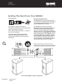
User
Manual
MODEL: QM 350i
Contents
Safety Precautions . . . . . . . . . . . . . . . . . . . . . . . . . . . . 1
General Description. . . . . . . . . . . . . . . . . . . . . . . . . . . . 3
Getting The Best From Your QM350i. . . . . . . . . . . . . . . 4
Flying the QM350i. . . . . . . . . . . . . . . . . . . . . . . . . . . . . 6
QM350i Specifications. . . . . . . . . . . . . . . . . . . . . . . . . . 8
QM350i Reference Diagram. . . . . . . . . . . . . . . . . . . . . . 9
User Manual
Q Motion Series
QM350i
QM350i
User Manual
Safety Precautions
• Be sure to read the instructions in this section carefully before use.
• Make sure you observe the instructions in this manual as the conventions of safety symbols and
messages are very important.
• We also recommend you keep this instruction manual handy for future reference.
Safety Symbol and Message Conventions
Safety symbols described below are used in this manual to prevent bodily injury and property
damage which could result from mishandling. Before operating your product, read this manual first
and understand the safety symbols and messages so you are thoroughly aware of any risks.
1
WARNING
Indicates a potentially hazardous situation which, if
mishandled, could result in death or serious personal injury.
Q Motion Series
QM350i
User Manual
QM350i
User Manual
WARNING
When Installing the Unit
• Do not expose the unit to rain or an
environment where it may be exposed to
water or other liquids, as doing so may
result in damage to the bass driver or
corrosion of the steel protective grill.
• Do not cut, kink, otherwise damage
nor modify the speaker cable. Also use
speaker cable of at least 1.5mm core
diameter. In addition, avoid locating the
speaker cables close to heaters, high
traffic areas or locations where the cables
can be damaged.
2
• Avoid installing or mounting speaker
boxes in unstable locations and when
flying, use the hardware designed for the
speaker box and fix securely to a solid
wall. Failing to do so may result in the
unit falling, causing personal injury and/or
property damage.
• Be sure to ground to the safety ground
(earth) terminal to avoid electric shock.
Never ground to a gas pipe as a
catastrophic disaster may result.
• Never hang a speaker box from only
one rigging point. Use multiple points
and attach a safety line to a point strong
enough to take the weight of the speaker
box.
User Manual
Q Motion Series
QM350i
When the Unit is in Use
• Turn down the amplifier before switching
on the amplifier. If there is no sound,
check the speaker connections. Speakon
connectors must be locked in place.
• Should any of the following irregularities
be found during use, immediately switch
off the amplifier power, disconnect the
power supply plug from the AC outlet and
contact your nearest Quest dealer:
• If you detect smoke or a strange smell
coming from the unit,
• If the unit falls and the unit case is
damaged,
• If it is malfunctioning (no HF or low
frequency output).
Make no further attempt to operate the unit if
it is found to be in any of the above conditions
as this may cause fire or electric shock.
QM350i
User Manual
General Description
These are intended to be used with the
WB350i wall bracket.
The QM350i is a passive two way bass
reflex design speaker suitable for mobile or
installation use. The design characteristics of
the QM350i make it suitable for both full range
use or as the high-mid component of a multi
way system with sub-bass enhancement.
QM Range Flying Accessories
The new generation neodymium high
frequency transducer is matched to a
rotatable asymmetrical wave guide that can
be rotated through 270 degrees for horizontal,
vertical or fold-back monitor installation.
The asymmetrical coverage allows the horn
to achieve both long throw performance
and wide angle close coverage without
“hot zones” or adding to unnecessary room
reflections that can degrade vocal intelligibility. The unit can be used in a stand alone
configuration or as part of a system coupled
with any Quest sub-bass system. When used
in conjunction with these devices, the QM350i
will form part of a high performance multi
way audio system.
Two rigging accessories are available for the
QM350i:
WB 350i Wall bracket kit
QB450 Protective transit cover
Functional Design
The QM350i features an asymmetrical
horizontal angle along one side which makes
it suitable for use as a stage\foldback wedge
when laid flat. The QM350i can be easily
maneuvered across a stage or down a loading
ramp by one person.
Solid Build Construction
The QM350i is well suited to all professional
applications. The synthetic casing is specially
formulated to withstand demanding use
and the heavy gauge power-coated steel
grill ensures the driver and horn are always
protected.
3
Installation
Temporary installation is possible with the
35mm floor stand mounting in the base of
the enclosure. Fold-back installation can give
extra uniform stage performance by rotating
the horn flare to the “fold-back” position.
Five M 8 thread inserts are located on the top,
sides and one under the QM350i enclosure.
WARNING
Flying the box from one insert must not be attempted! Improper
installation may result in damage, injury or death.
Q Motion Series
QM350i
User Manual
QM350i
User Manual
Getting The Best From Your QS350i
Connections
Suitable Amplification
The QM350i is an 8 ohm enclosure and can
be connected in multiple parallel connections
to an amplifier channel that can operate at
speaker impedances of 4 ohms.
The QM350i is a mid power level high
efficiency system, so ultra high power is not
necessary to obtain high sound pressure
levels. The recommended power range per
amplifier channel is 350 - 500 watts RMS into
an 8Ω load or up to 1,000W RMS into a 4 ohm
load. An ideal partner to the QM350i are any
of the Quest QA range of amplifiers. Setting
the QA amplifier’s high pass filter at 35Hz is
recommended for full range applications. If
you are intending to add sub bass speakers,
the high pass filter can be set to 80Hz.
Two Neutrik™ Speakon model NL-4
connectors are mounted in a removable panel
on the rear surface of the box.
The connector input is wired pin 1+ and pin 1-.
Pin 2 is not connected.
Take care when inserting the Speakon
connector twisting the connector until it
locks into place. Reverse the procedure to
disconnect.
4
10
10
5
5
35Hz
80Hz
HIGH PASS -A
Reducing low frequency output will make more
amplifier power available for clean vocal reproduction
for full range sound, set the high pass filter to 35Hz
1
1
1
OFF
2
OFF
35Hz
80Hz
STEREO PARALLEL BRIDGE
HIGH PASS -A
OFF
LINK A
PIN1:
PIN2:
PIN3:
80Hz
1.4V
MODE
32dB
26dB
GAIN
OUTPUT A
CAUTION
RISK OF ELECTRIC SHOCK
DO NOT OPEN
110Hz
LOW PASS -A
INPUT A
SIGNAL G N D
SIG N AL +
SIGNA L -
BRIDGE
MODEL:
OUTPUT ASSIGNMENT
PIN 1+ :
S IGN A L
PIN 1- :
GROUND
Push To Reset
HIGH PASS -B
OFF
35Hz
80Hz
LIMITER
LOW PASS -B
OFF
LINK B
INPU T B
80Hz
110Hz
ON
GROUND
OFF
LIFT
GROUND
DESIGNED BY QUEST ENGINEERING,AUSTRALIA
OUTPUT B
~ 220
240V 10A 50/60Hz
Recommended QM350i Amplifier Configuration
User Manual
Q Motion Series
QM350i
QM350i
User Manual
Speaker cables
Speaker cable needs to be as heavy gauge
as conveniently possible for low-loss results.
Light gauge cable (below 1.5mm) will create
extra resistance and waste amplifier power.
This particularly applies to long speaker
runs. The amplifier’s damping factor statistic
(“punch” for the non technical) is greatly
diminished, so keep your speaker cables
short and as heavy gauge as practical.
Speaker Placement as a Single Box
or in Arrays
The QM350i is intended for use as a single
speaker system or as part of a multiple
speaker setup with or without sub bass
reinforcement. It can also be installed in small
arrays of up to three boxes per array for very
wide coverage applications. When a group
of point source 90 degree speaker boxes
are placed together, it is possible to have
“interference effect” between some of the
boxes causing uneven frequency response.
This can be particularly noticeable in the
mid-high frequency area. If you intend to set
up the QM350i as part of a multiple box array,
see the section ‘Flying the QM350i’.
When positioning the speaker system on a
stage, make sure the HF horn at the top of
the speaker box is above the heads of the
audience. At full power the output of the
QM350i is very high and hearing damage can
result from short to medium term exposure.
When used as a drum-fill monitor on a stage,
the box can sit on the stage however consider
that the HF horn will be at ear level for the
average drummer setup.
For best results when the QM350i is used as
a front of house speaker, consider angling the
box forward slightly to direct the HF horn to
cover the audience area. The HF horn should
be aimed away from the ceiling and focused
on the intended area of coverage. This will
minimize HF reflections, lower the reverberant
field in the room and give better intelligibility.
5
Ideal QM350i Flown Configuration
Q Motion Series
QM350i
User Manual
QM350i
User Manual
Flying the QM350i
6
Before suspending any speaker system
always inspect all components (enclosure,
rigging frames, track fittings, etc.) for cracks,
deformations, corrosion, missing, loose or
damaged parts that could reduce strength
and safety of the array. Do not suspend the
speaker system until the correct preparation
of the installation site has been taken to avoid
health risks during and after the completion
of the installation. A licensed Professional
Engineer must approve the placement and
method of attachment to the structure prior to
the installation of any overhead object.
Rotating the Horn Flare
The asymmetrical horn flare can be rotated
through three separate planes of dispersion
depending on the speaker box requirement
and installation environment. The planes are
vertical installation, horizontal installation and
foldback monitor.
Good coverage of audiences often requires
wide dispersion at the base of the horn flare
to cover close listeners and a focused narrow
dispersion at the top of the flare to beam to
the back of the room.
The QM350i horizontal horn covers both
“short-throw” and “long-throw” requirements
in a single system.
WARNING
User Manual
Q Motion Series
QM350i
For the majority of installations (where the
box is installed vertically), the asymmetrical
horn should be used as supplied and will not
need to be rotated.
For horizontal installation rotate 45 degrees
so the arrow is pointing at the floor side so
as to have the “beaming” facility at the top of
the horn.
Foldback HF coverage
For stage foldback monitors the coverage
must be wide when performers are close
to the wedge and beam down the stage
to minimize the spill off the stage that may
interfere with the main PA.
For floor monitor use the horn must be
rotated with its “wide” dispersion (arrow
indicator), side directed towards the top of
the horizontal floor cabinet.
When removing and reinstalling the front grill
to rotate the horn, ensure the nuts are not
over tightened as this may make them difficult
to remove in future or cause them to break.
If damaged, the cage nuts can be replaced
easily with standard rack mount cage nuts.
Ensure the box is securely located. If any doubt about the physical
stability, tie the box down with ratchet straps to a secure base.
QM350i
User Manual
QM350i Wave Guide Examples
45°
+15°
-45°
90°
QM350i FOH Configuration (front)
QM350i FOH Configuration (side)
-45°
90°
7
+15°
45°
QM350i Foldback Configuration (front)
QM350i Foldback Configuration (side)
45°
+15°
90°
QM350i Horiztonal Configuration (front)
-45°
QM350i Horizontal Configuration (front)
Q Motion Series
QM350i
User Manual
QM350i
User Manual
QM350i Specifications
110
100
90
80
70
60
50
8
20
50
100
200
500
1k
2k
5k
10k
20k
Frequency (Hz)
QM350i - Frequency Response - 2.83V/1m
Technical Parameters
User Manual
Power Handling
400W RMS
Frequency Response
60-19kHz (+/-3dB)
Sensitivity
95dB @ 1kHz
Maximum SPL @ 1m
128dB
Impedance
8 ohms
Connections and Wiring
2 x Speakon NL4 - 1+/1- (2+/2- through)
Woofer
12” High Power Mid-Bass Woofer
Tweeter
1” Neodymium Compression Driver
Directivity
Asymmetric +15/-45 Vertical | 45/60
Horizontal
Dimensions
620x380x346.5 mm
Weight
19.7 kg Net
Q Motion Series
QM350i
QM350i
User Manual
QM350i Reference Diagram
4 - compression driver
4bis - diaphragm
6 - complete x-over
7 - connection plate
1 - complete grille
8 - complete connection plate + x-over
9 - side skids (182mm)
9
11 - pole mount plate
2 - rotating Q badge
10 - bottom skids (137mm)
5 - 12inch woofer
5bis - woofer recone kit
No.
Description
Spare Part
1
Complete Grill (with Acoustic Foam)
HGQM350
2
Rotating Q-badge (23mm) with Spring Loaded Pin
HQB25
3
Horn Flare (Wave Guide)
HWG350
4
1” Compression Driver
T1009
1” Compression Driver Diaphragm
RT1009
12” Woofer
T12001
4bis
5
5bis
12” Woofer Recone Kit
RT12001
6
Complete X-Over
HXQM350
7
Connection Plate
HCPQM350
8
Complete Connection Plate and Complete X-Over
HCCPQM350
9
Long Skids (182mm)
HSK182
10
Medium Skids (137mm)
HSK137
11
Pole Mount Plate
HPP350
Q Motion Series
QM350i
User Manual
Register Your Product
Thank you for choosing Quest. Please take the time
to complete your product registration card which is
included with the packaging.
Registering your Quest Engineering product will:
• CONFIRM YOUR WARRANTY
• REGISTER YOUR PRODUCT
• PROTECT YOUR NEW PRODUCT
REGISTER ONLINE:
www.questaudio.net/registration
www.questaudio.net