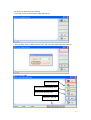
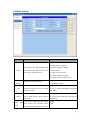
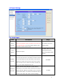
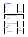
1
SANAV GPS Tracker Utility Setup Guide
Revision: 1.0.2
Revision Date: 2013/08/1
1.
Notification ..................................................................................................................3
1.1
1.2
1.3
1.4
Introduction:......................................................................................3
Disclaimer............................................................................................3
Copyright..............................................................................................3
Document Amendments..............................................................4
2. Installation ......................................................................................................................5
2.1 Connect the device to your PC....................................................5
2.2 Start up GPS Tracker Utility .........................................................6
3. Setting Function.............................................................................................................7
3.1 User Settings:..............................................................................................7
3.1.1 Security Settings: ...........................................................................7
3.4 Report Settings ......................................................................................... 11
3.4.1 Auto Report..................................................................................... 11
3.4.2 Over Speed Settings ....................................................................12
3.4.3 Panic.................................................................................................12
3.4.4 Move .................................................................................................12
3.4.5 Geofence .........................................................................................12
3.4.6 Report Tail.......................................................................................13
3.5 Geofence Settings....................................................................................14
3.6 Vibration Settings.....................................................................................15
3.7 Power Settings ..........................................................................................16
4. Button Function ...........................................................................................................17
5. FAQ ...............................................................................................................................18
2
1. Notification
1.1 Introduction:
This User Manual details how to make the connection from SANAV MU-201 Nano Tracker to
your PC. It also details all the features and configuration of GPS Tracker Utility. If you have
any problem with the content in this manual, please contact SANAV Customer Service by
e-mail [email protected].
1.2
Disclaimer
This document, and all other related products, such as device, firmware, and software, is
developed by SAN JOSE TECHNOLOGY INC. thoroughly. At the time of release, it is most
compatible with specified firmware version. Due to the functionalities of the devices are being
developed and improved from time to time, the change in the protocol, specification, and
firmware functions are subjects to change without prior notice. SANAV is obligated to modify
all the documentation without the limitation of time frame. A change notice shall be released
to SANAV customers upon the completion of document modification.
SANAV products are not intended to be used as life support or rescue equipments. SANAV is
not liable for any loss or injury caused by using or referencing to any products. Any possible
means of using or integrating SANAV products shall be avoided.
1.3
Copyright
The all parts of intellectual rights applicable in the copyright laws in all the countries are held
by San Jose Technology Inc., any or all parts of this document shall not be exposed to
non-authorized party without any form of approval from San Jose Technology Inc. Any forms
including but not limited to oral, copy, or internet sharing, of releasing or exposing
information to an unauthorized party shall be prohibited. San Jose Technology Inc. reserves
the rights of litigation in the violation of such copyright laws.
3
1.4
Document Amendments
Revision
Date
GPS Tracker Utility Version
Comments
1.0.1
2012/7/17
V1.01
Optimized for MU-201, MU-58
1.0.2
2013/8/1
V1.02
Modify schedule function :To
enable/disable all the stages of
schedule.
4
2. Installation
2.1 Connect the device to your PC
1. Install the USB Driver and the GPS tracker Utility in the CD.
2. Turn on MU-201 before connecting it to a PC.
3. Plug in the AP Cable (connect USB to PC and Mini USB to MU201).
4. Check the COM Port from “Hardware Manager” in Windows OS
5
2.2 Start up GPS Tracker Utility
4. The main screen of GPS Tracker Utility (MU Series).
5. Execute GPS Tracker Utility. Click on “Port” and select the Comm Port then Connect
6. Features on utility
Setting Function
Download Flash Backup data
Erase Flash Backup data
Firmware Version
6
3. Setting Function
3.1 User Settings:
Username: At the maximum of 16 letters. (Letters have to be “a~z, A~Z, 0~9, @ - /”)
Pin Code: 4 digits of number to enable SIM service
Password: 4 digits of number
Phone Book: 3 sets of phone number. Max: 19 digits
SOS Phone: 1 set of phone number, Max.19 digits
Note that both adding and not adding the “+ “sign in front of the cellular phone number(s) are
both acceptable, while the”+” sign should precede the national code.
3.1.1 Security Settings:
Security Phone Switch: Enable or Disable Security Phone function.
Security Phone Book: You can input 10 sets of Security Phone Numbers here.
7
3.2 GPRS Settings:
:
Route :
Representation
Router code
0
HTTP/SMS, send data to URL, if the URL is untouchable, then send it via SMS instead.
2
HTTP only, send data to URL, if the URL is untouchable, it won’t send the data by SMS.
4
SMS only, send data by SMS only.
6
TCP/SMS, send data to an assigned IP address, if the IP is untouchable, then send it via SMS instead.
7
TCP Only, only send data to an assigned IP address.
8
UDP/SMS; send data to an assigned IP address, if the IP is untouchable, then send it via SMS instead.
9
UDP Only; only send data to an assigned IP address
APN: Define the APN for the GPRS communication
APN reference: http://forum.gpsgate.com/topic.asp?topic_id=6669
URL: For HTTP or HTTP/SMS protocol
TCP/UDP: The IP/Port for TCP, TCP/SMS, UDP or UDP/SMS protocol
(IP Address or Domain Name)
Setup Server: The IP/Port for COTA (commands by GPRS)
8
3.3 Mode Setting:
:
Field
Descriptions
Range
(0~1): Auto answer.
2: Hang up the call and
Voice
The tracker will respond differently
then send a POLL message
according to the settings when the
to call number
call center calls the device
3: Hang up the call and
then send a POLL message
to assigned URL or IP(By route)
Power
0: Power saving
GPS power saving setting
saving
1: No power saving
When
Crlf
Turbo
Power
report
router
is
set
to
0: turn off
TCP/UD, to add<CR><LF> for each
1: turn on, when send data to TCP/UDP
report sentence..
with CRLF
Keep the connection alive to the
0: turn off
server when report router is set to
1: turn on, after send don't close server
TCP/UDP.
connection
The device sends the last report
0: Off
with power
1:On
OFF
off message
when
Alarm
pressing power button to turn off it.
9
Charger
in
Auto ON
Power Key
The device automatically turns ON
0: Off
when plugging in charging cable
1:On
with power source.
To enable or disable power button
0: Off
function.
1:On
The language type of Google map
En-us, zh-tw,ar-AE…etc.
HTML
address (please refer to Google
Language
Hyperlink)
The GPRMC data shown on cell
0: link OFF, address OFF
phone can be replaced with Google
1: link ON, address OFF
map
the
2: link OFF, address ON
positions on map with address
3: link ON, address ON
Google
hyperlink
to
check
Hyperlink
directly
10
3.4 Report Settings
3.4.1 Auto Report
Field
Descriptions
Range
Report time interval
Report
Note* the numbers will be rounded to the next Time
A constant interval of
Interval
Unit automatically; you can put the number in the
sending data
preferred column of Time Units.
0~9999, where 0 means
Total
turning off the Auto
Amount of report
Report
Report and 9999 means
infinite
The distance interval when reporting by distance. When
the auto report function is activated, the tracker will take
Distance
the current position as the center point, if this value is
Interval
defined, the tracker will take this value as the radius in
0
~9999m
meter to make a circle. When the tracker exceeds this
circle, it will report assigned URL or IP.
Report interval when stationary. If this value is
defined by X, the tracker will do detection according to
Stationary
Report Interval. When it exceeds the circle, it will send
2~9999
Detection
out an AUTO report. If it doesn’t exceed this circle for
X times, the tracker will send a notice message.
11
3.4.2 Over Speed Settings
Field
Descriptions
Range
Over
0: Off
Speed
Over Speed Detection ON/OFF
1:On
Decect
Speeding
On
Speed Limit of Over Speed Event
1~65000 km/h
The report interval when Over Speed.
1~65000 in seconds
Threshold
Report
Interval
Total
1~9999, 9999 means
Amount of report
Report
infinite
3.4.3 Panic
Field
Descriptions
Range
Tick the “Panic” and the tracker will send report
Report
when the “SOS” is pressed. The tracker will
1~65000 in seconds
Interval
report periodically according to this setting.
Total
1~9999, 9999 means
Amount of report
Report
infinite
3.4.4 Move
Field
Descriptions
Range
Tick the “Move” and the tracker will send the
Report
report(s) when “Park” is activated and the
Interval
MU-201 is moved. it will then report periodically
1~65000 in seconds
according to the settings.
Total
1~9999, 9999 means
Amount of report
Report
infinite
3.4.5 Geofence
Field
Descriptions
Range
Tick the “Geofence” and the tracker will send
Report
the report(s) when the “Geofence” is activated
Interval
and triggered. It will report periodically
1~65000 in seconds
according to this setting.
Total
1~9999, 9999 means
Amount of report
Report
infinite
12
3.4.6 Report Tail
Field
Descriptions
Range
By enabling “Tail Report”, there will be
additional information included in each report
0: Off
Report Tail
data. The additional data including RSSI,
1: On
vibration sensor status, report number, charger
status, and Cell ID information.
Report Tail
Enter the corresponded letters to determine
Seqence
how much tail information would be shown
ABCDEFGHIJ
Voltage
0: Off
The device voltage indicator shown in %
Percentage
1: On
13
3.5 Geofence Settings
Field
Descriptions
Range
Lat.
Latitude
dd.dddddd
Long.
Longitude
ddd.dddddd
Range
Radius in meter
100~9999 meters
0: Off
1: Exclusion
Geofence Mode
Geofence trigger setting
2: Inclusion
3: Exclusion and Inclusion
14
3.6 Vibration Settings
Note:
If you have set up VS as well, GPS will be in power saving mode when the device stop moving
for more than 3 minute (Default 180 seconds, you can change the number to
60/120/180/240/300 secs)
Field
Descriptions
off
Disable Vibration Function
on
Enable Vibration Function
Hide
To hide Move/Stop status messages
Show
To show Move/Stop status messages
Range
Vibration Sensitivity
Field
Descriptions
Range
1: High
High Vibration Sensitivity
1 – Most sensitive to vibration
2: Middle
Middle Vibration Sensitivity
2 – lesser sensitive to vibration
3: Low
Low Vibration Sensitivity
3- Least sensitive to vibration
15
3.7 Power Settings
Field
Descriptions
Range
User can use the command to set up the
ON
power on/off schedule per day of the
ON: Power ON
device.
OFF: Power OFF
There are totally 4 stages of a day can
be scheduled.
0000
GMT time
Enable all
Power ON all the 4 stages of schedule
0000~2359
※If the user wants to disable any one
of four stages of “Schedule Power
Disable all
To disable all the 4 stages of schedule
Switch” , they must select “Disable all”
then change the status for each status
of “Schedule Power Switch” .
16
4. Button Function
Save: To save the setting that has been done. After saving the setting, reboot the
MU-201 in order to restore the new setting.
Load: To view the current settings.
Default: All parameters returned to default
Save File: Save the current setting as a file
Load File: Load previous file of setting.
Close: Exit the utility
17
5. FAQ
Please turn ON MU-201 before connecting to PC.
Please check if you have installed USB Driver.
Please check the correct COM Port in Device Manager
Not in command mode
(Windows)
Please make sure you used the correct USB Data Cable
(Not the charging Cable.)
18