1
tordless lmpatt Wrenth & Llght
which may ignite the dust or fumes
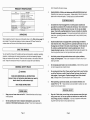
PRODUCT SPECIFICATIONS
Hem
Elscrrlcal Rsqunrements
Drlve S l l s
Trigger Type
Daserlptlon
Power o u l p u t t 9 2 v D c
Power Input 120 VACwo Hz Cnarger
Baltery Type 1 7Ah NI-Cd
charge Time. 1 Hour Fasl Charge
Charqsr Power Plug 2 Prong Polar~zetl
1R"
Uar#4DleSpeed
-
Keep bystanders, children, and visitors away while operating a power tool.
Distractions can cause you to lose control. Protect others in the work area from
debris such as chips and sparks. Provide barriers or shields as needed
0-2000 R P M
Reversible
WO Ft ILbs.
4 O t y - Slzes. X 716' .15H6",1"
21 L x 4 318" W x 15' H
14 30PounIls
Marlmum Torqus
Sockets Included
Overall Dtmensluns
Wetgnt
.
UNPACKING
When unpacking, check to make sure all the parts shown on the Parts List on page 13
are included If any parts are miss~ngor broken, please call All-Power Tools at the
number shown on the cover of this manual as soon as posslble
SAVE THIS MANUAL
You w~llneed th~smanual for the safety warnings and precautions, assembly, operat~ng,
inspection, rna~ntenanceand clean~ngprocedures, parts lisl and assembly d~agrarn.
Keep your invoice with this manual. Write the invoice number on the inside of the front
cover Keep thls manual and invoice in a safe and dry place for future reference
GENERAL SAFETY RULES
A WARNING!
READ AND UNDERSTAND ALL INSTRUCTIONS
Failure to follow all instructions listed below may result in
electric shock, fire, andlor serious injury.
SAVE THESE INSTRUCTIONS
I
WORK AREA
1
1
Keep your work area clean and well lit. Cluttered benches and dark areas
invite accidents.
2.
Do not operate power tools in explosive atmospheres, such as in the
presence of flammable liquids, gases, or dust. Power tools create sparks
Page 2
Grounded tools must be plugged into an outlet properly installd and
grounded In accordance with all codes and ordinances. Never remove the
grounding prong or modify the plug in any way. Po not use any adapter
plugs. Check with a qualified electrician if you are in doubt as to whether
the outlet is properly grounded. If the tools should electrically malfunctlon or
break down, grounding provldes a low resistance path to carry electrlclty away
from the user.
Double insulated tools are equipped with a polarized plug (one blade is
wider than the other). This plug will fit in a polarized outlet only one way. If
the plug does not fit fully in the outlet, reverse the plug. If It still does not
fit, contact a qualified electrician to install a polarized outlet. Do not
change the plug in any way. Double lnsulatlon
ellmlnates the need for the
three wire grounded power cord and grounded power supply system
Avoid body contact with grounded surfaces such as pipes, radiators,
ranges, and refrigerators. There IS an increased rlsk of electric shock if your
body is grounded
Do not expose power tools to rain or wet conditions. Water entering a power
toot will Increase the rlsk of electrlc shock.
Do not abuse the Power Cord. Never use the Power Cord to carry the tools
or pull the Plug from an outlet. Keep the Power Cord away from heat, oil,
sharp edges, or moving parts. Replace damaged Power Cords immediately. Damaged Power Cords increase the risk of electric shock.
When operating a power tool outside, use an outdoor extension cord
marked "W-A" or " W . These extension cords are rated for outdoor use, and
reduce the risk of electric shock.
1 PERSONAL SAFETY I
Stay alert. Watch what you are doing, and use common sense when opersting a power tool. Do not use a power tool whlletired or under the influenceoi drugs, alcohol, or medication. A moment of mattention while operating power tools may result In serrous personal injury
Page 3
Dress properly. Do not wear loose clothing or jewelry. Contain long hair.
Keep your hair, clothing, and gloves away from moving parts. Loose
clothes, jewelry, or long hair can be caught In moving parts
Avoid accidental starting. Be sure the Power Switch is off before plugging
in. Carrying power tools with your finger on the Power Switch, or plugglng in
power tools w~ththe Power Swltch on, Invites accidents.
7
Check for misalignment or binding o i moving parts, breakage of parts, and
any other condition that may a f f w the tool's operation. ll damaged, have
the tool serviced before using. Many accidents are caused by poorly maintained tools.
8.
Use only accessories that are recommended by the manufacturer for your
model. Accessories that may be suitable for one tool may become hazardous
when used on another tool.
1.
Tool service musl be performed only by qualified repair personnel. Service
or ma~ntenanceperformed by unqualified personnel could result in a risk of Injury
2.
When servicing a tool, use only identical replacement parts. Follow
instructions in the 'lnspecfion, Maintenance, A n d Cleaning"9ection of this
manual. Use of unauthorrzed parts or failure lo follow maintenance rnstructions
may create a risk of electr~cshock or injury.
Remove adjusting keys or wrenches before turning the power tool on. A
wrench or a key that is left attach& to a rotatrng part of the power tool may result
in personal injury.
Do not overreach. Keep proper lootlng and balance at all times. Proper
footing and balance enables better control of the power tool in unexpected
situations.
Use safety equipment. Always wear eye ANSI-approved safety impact eye
goggles. Dust mask, non-skid safety shoes, hard hat, or hearing protection
must be used for appropriate conditions.
SPECIFIC SAFETY RULES
ITOOL USE AND CARE]
1
Maintain a safe working environment. Keep the work area well lit. Make sure
there is adequate surrounding workspace. Always keep the work area free of
obstruct~ons,grease, oil, trash, and other debris. Do not use the lmpact Wrench
In areas near flammable chemicals, dusts, and vapors. Do not use this product
In a damp or wet location
Do not force the tool. Use the correct-tool for your application. The correct
tool wrll do the job better and safer at the rate for which it I S deslgned
2
Do not use the power tool if the Power Switch does not turn It on or off.
Any tool that cannot be controlled with the Power Swltch IS dangerous and must
be replaced.
Maintain labels and nameplates on the ImpactWrench. These carry
Important information. If unreadable or mlssing, contact Harbor Freight Tools for
a replacement.
3
When using the lmpact Wrench, always maintain a firm grip on the tool with
both hands.
Disconnect the Power Cord Plug from the power source bdore making any
adjustments, changing accessories, or storing the tool. Such preventive
safety measures reduce the risk ot starting the tool accidentally.
4.
Do not use the lmpact Wrench or Charger (39) il It has been dropped, dama g d , left outdoors, or immersed In liquid.
Store idle tools out of reach of children and other untrained persons. Tools
are dangerous in the hands of untrained users.
5.
Do not charge the Battery (37) when the temperature is below 50 degr-s
Fahrenheit or above 104 degrees Fahrenheit.
Maintain tools with care. Keep tools clean and dry. Properly malntained
tools wlth a sharp cutting edge are less likely to bind and are easier to control
Do not use a damaged tool Tag damaged tools "Do not use" until repaired.
6.
Do not shake, drop, or strlke the Battery (37).
7.
To avoid electrical shock, do not pull or carry the Charger (38)by Its
Power Cord or pull the Power Cord around sharp corners or edges. Do not
Use clamps (not included) or other practical ways to secure and support
the workpiece to a stable platform. Holdlng the work by hand or against your
body is unstable and may lead to loss of control.
Page 4
Page 5
unplug the Charger by pulling on the Power Card. Keep the Power Cord
away from heated surfaces
8.
9
10.
11.
-.
-
I
SYMBOLOGY
To avoid electrical shock, do not handle the Charger (391, its Power
Cord Plug, or the lmpact Wrench with wet hands.
D
l
Canadlan StandaKls
Association
Keep the Handle of the Impact Wrench dry, clean, free from oil and
grease.
Avoid unintentional starting. Make sure you are prepared to begin work
before turning on the lmpact Wrench.
V
,
A
Never leave the Charger (39) unattended when it is plugged into an
eltxtrical outlet. Make sure to unplug it from its electrical outlet before leaving
12
Atways turn off the Impact Wrench and unplug the Charger (39) from
its electrical outld before changing accessories or performing any inspection, maintenance, or cleaning procedures.
13.
Always switch to a fresh Battery (37) when tool performance begins to
diminish. Severe heat is most destrucllve to a Battery The more heat generated, the faster the Battery loses power. A Battery that gets too hot can be permanently damaged Never over-discharge a Battery by using the tool even after
tool performance is decreasing. Never attempt to d~schargea tool's Battery by
continuing to pull the tool's trigger When tool performance beg~nsto diminish,
stop the tool, recharge the Battery, and use the fresh Battery for optimal performance
FIGURE C
Volts Alternating Current
Amperes
1
No Load Revollnions
per Minute(RPM)
PRODUCT FEATURES
N O I c For additional information regarding the parts listed in the following pages, refer
to the Assembly Diagram on page 73.
1.
Battery (37) leakage may occur under extreme usage or temperature condl-
tions. If Battery flurd comes In contact with skin, wash with soap and water and
15.
Underwriters
h b ~ ~ t ~ r i t1%
°C.i ,
@
no K!2&m'n*
14.
Double InsulaZed
1-
Always make sure the Trigger (36) of the lmpact Wrench is in
its "OFF" posit~on,the Battery (37) is removed from the lmpact Wrench, and the
Charger (39) is unplugged from its electical outlet prior to making any adjustments to the tool. {See Figure I),next paqe.)
rinse with lemon juice and vinegar If the fluid comes into contact with the eyes,
flush with water for several minutes and contact a doctor immediately.
2.
Never burn the Battery, as it can explode in a fire. Do not charge the lmpact
Wrench wlth a leaking Battery. Contact local solid waste authorities for instructions on correct disposal or recycling of the Battery.
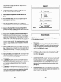
Irigaer (361: The Trigger is operated manually simply by squeezing the Trigger to
turn on the lmpact Wrench and releasing pressure on the Trigger to turn off the
lmpact Wrench. (See Figure D.)
3.
ForwaKYReverse Switch (32):The ForwardlReverseSwitch allows you to change
the rotatronal direct~onof the lmpact Wrench. For a clockwise rotation, move the
ForwardIReverse Button to the right. For a counterclockwise rotation, move the
ForwardIReverse Button to the left. To avoid damage to the lmpact Wrench,
always wait untll the tool completely stops before changing rotational directions.
(See Flgure P.)
4.
112" Drlve lmpact Head
The 1/2"lmpact Head features a spring and ball to
securely hold a socket. The lmpact Head accepts all sizes of standard and metric
sockets having a 1/ 2 drlve. (See Figure D.)
16.
1
17.
1
I
B W A R N I N G ! People wth pacemakers should consult ther physican(s)
before using this product. Operation of electrical equipment in close proximity to
a heart pacemaker could cause interference or failure of the pacemaker
WARNING! lThe warnings, precautions, and instructions discussed in this
manual cannot cover all ~ossibleconditions and s~tuationsthat may occur The
operator must understand that common sense and caution are factors, which
cannot be built into this product, but must be supplied by the operator.
Page 6
m:
5.
Battery i37): The power source for the Impact Wrench is a rechargeable,
19.2VDC Battery. Make sure to follow all safety precautionswhen working with the
Battery. (See Figure D.)
6.
Charger (39): The Charger is powered by plugging its Power Plug into a 120 volt,
grounded, electrical outlet. NEVER attempt to power the Charger wlth any other
electrical source other than a 120 volt, grounded electrical outlet. (See Figure D.)
5.
Verify that the RED Charging Indicator Ught comes on. If it does not iliuminate,
check the power connection or try a different electrical outlet. Charge the Battery
(37) for 1 hour. NOTE: When the Battery is fully charged the RED Charging
Indicator Light WIH turn off, and the GREEN Charged L~ghtwill illuminate. Subsequent charglng can also be done in 1 hour. (See Figure D.)
6.
While charging, the Battery (37) and Charger (39) may become warm to the touch.
Thls is normal, and does not lndicate a problem. (See Figure D.)
7.
Once the Battery (37) is fully charged, disconnect the Charger (39) from the
electrical outlet. Remove the Battery from the Charger, and insert the Battery
into the handle of the Impact Wrench. (See Figure 0.)
8.
N O I E Ifcharging more than one Battery (37), allow the Charger (39) to cool
down before reusing. (See Figure D.)
CONNECT TO
ELECTRICAL
I
I.
Before installing a socket, make sure the Battery (37) is removed from the lmpact
Wrench to avold accidental starting. Then, firmly insert the Socket onto the 112"
lmpact Mead ( 7 ) of the tool. (See Figure D.)
2.
Whenever possible, secure the workpiece in place, using a vise or clamps (not
included).
3,
Insert the fully charged Battery (37) into the handle of the Impact Wrench.
(See Figure D.)
FIGURED
TO CHARGE THE IMPACT WRENCH
OPERATING INSTRUCTIONS
1.
NOTE: The Battery (37) requires charging. The first charge requires 1 hour
c'harge time prior to using the Impact Wrench. (See Figure D.)
4.
Use the Forward/Reverse Switch (32) to select the turning rotation of the lmpact
Wrench. (See Figure D.)
2.
The Battery (37) should only be recharged when the lrnpact Wrench begins to
run slowly. (See Flgure D.)
5,
Insert the socket onto the nut that is to be loosenedhightened
3.
When the Battery (37) requires recharging, a 1 hour charge allows the tool to
operate at full power. Do not recharge the Battery lonaer than 1 hour, as d a r n a ~
to the Battery and/or Impact Wrench will occur. {See Figure 0.)
6.
Make sure to hold the Impact Wrench firmly wlth both hands, as torque from the
Motor will cause the tool to twist. Then, squeeze the Trlgger (36)to turn on the
lmpact Wrench. (See Figure D.)
Make sure the Trigger (36) on the lmpact Wrench rs In its "OFF' position. Slide
the Battery (37) oft the handle of the lmpact Wrench. Insert the Battery into the
charglng socket of the Charger (39).Then plug the Charger !nto the nearest 120
volt, grounded, electrical outlet. (See Figure D.)
7.
4.
When finished, release the Trigger (36) to stop the Impact Wrench. Then, remove the Battery (37) and socket from the tool. (See Figure D.)
8.
Make sure to store the lmpact Wrench in a dry, clean location out of reach of
chlldren and other unauthor~zedpeople.
Page 8
Page 9
I
INSPECTION, MAINTENANCE, AND CLEANING
1.
/7\ WARNING! Always let the Trigger (36) rest in Its "OFF" position, remove
the Battery (37) from the tool, and unplug the Charger (39) from its electrical
outlet before performing any inspection, maintenance, or cleaning.
2.
Before each use: Inspect the general condition of the lrnpact Wrench. Check for
misalignment or binding of moving parts, cracked or broken parts, leaking Battery,
damaged Charger wiring, chipped or broken sockets, and any other condition that
may affect its safe operation. If abnormal noise or vibration occurs, have the problem corrected before further use.
Do not use damaged equipment.
3.
Daily: With a clean cloth, remove all dirt, grease, and oil from the lrnpact Wrench.
Po not immerse the Impact Wrench in any liquids.
4.
It may become necessary at sometime to replace or clean the two Carbon Brushes
(29) when the Motor performance decreases, or stops working completely.
To replace the Carbon Brushes: Remwe the two Brush Holder Caps (28). Then,
keeprng track of the orientation and location
remove the two Carbon Brushes (291,
of each. If either Carbon Brush is worn more than halfway, replace both Carbon
Brushes. If the Carbon Brushes are just dirty, however, they may be cleaned by
rubbing them with a pencil eraser. If cleaning and replacing used brushes, try to
install them in the same holders and in the same direction they were removed. When
installing the Carbon Brushes, make sure the carbon portion of the Carbon Brushes
contact the Motor's Rotor and that the spnngs face away from the Motor. Also, make
sure the springs operate freely. After replacement or cleaning, replace the two Brush
Holder Caps.
NOTE: New Carbon Brushes tend to arc or spark when f~rstused until they wear
and conform to the Motor's Rotor.
5.
1
PARTS LIST & ASSEMBLY DIAGRAM
f
lhght head
?ar
lamlc gear
APT1 Ol6A-A-22-TB I Master sham
APT1 016A-A-23-T R I Screw
APT1 0Z6A-A-24-TB I Right body
I APT1011
1 APT1011
Sw~tch
Battery clan
1
/
!
l
CAUTION! All maintenance, service, or repairs not listed in this manual
are only to be attempted by a qualified service technician.
PLEASE READ THE FOLLOWING CAREFULLY
THE MANUFACTURER AND/OR DISTRIBUTOR HAS PROVIDED THE PARTS LlST AND ASSEMBLY
DIAGRAM IN THIS MANUAL AS A REFERENCE TOOL ONLY. NEITHER THE MANUFACTURER OR
DISTRIBUTOR MAKES ANY REPRESENTATION OR WARRANTY OF ANY KIND TO THE BUYER THAT
HE OR SHE IS QUALIFIED TO MAKE ANY REPAIRS TO THE PRODUCT, OR THAT HE OR SHE IS
QUALIFIED TO REPLACE ANY PARTS OF THE PRODUCT IN FACT, THE MANUFACTURER AND/OR
DlSTRlBUTOR EXPRESSLY STATES THAT ALL REPAIRS AND PARTS REPLACEMENTS SHOULD BE
UNDERTAKEN BY CERTIFIED AND LlCENSEDTECHNIC1ANS. AND NOT BY THE BUYER. THE BUYER
ASSUMES ALL RISK AND LIABILITY ARISING OUT OF HIS OR HER REPAIRS TO THE ORIGINAL
PRODUCT OR REPLACEMENT PARTS THERETO. OR ARISING OUT OF HIS OR HER INSTALLATION
OF REPLACEMENT PARTS THERETO
Page 10
NOTE:
Some parts are listed and shown for illustration purposes only,
and are not aavilable individually as replacement parts.
Page 11
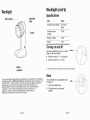
Worklight (cont'd)
Worklight
Specifications
adjustable
head
bulb housing
-
switch
Item
Value
Charger input voltage
110-120V
Charger output
voltage
19.2V
Battery voltage
19.2V
Power
10W
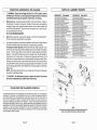
Turning on and off
Grip the work'light firmly with your index
finger on the on-off switch.
Slide the switch to " I " for operation
Slide the switch to " o " for off
1
battery
recepticle
switch-t
/
* The power switch my be located on the back of some models
Neck
Your new cordless worklight has been engineered and manufactured to the highest
possible standards by All-Power Americafor dependability, ease of operation, and
operator safety. Properly cared for, it will give you years of rugged, trouble-free
performance. Every care has been taken to ensure that it reaches you in
perfect condition. However, in the unlrkely event that you should experience
a problem, or if we can offer any assistance or advice, please do not
hesitate to contact our customer care department at the address or
telephone number listed at the back of this manual.
Page 12
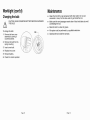
Your worklight has an adjustable head,
To adjust it:
1 Grip the worklight body
2 Twist the neck to the desired
position.
Page 13
neck
/
I
Worklight (cont'd)
Changing the bulb
CAUTION: ALWAYS REMOVE BATTERY BEFORE CHANGING
THEBULB.
Maintenance
Clean the tool with a rag dampened with clean water. Do not use
chemicals or soap. Do not allow water to get inside the tool.
Make sure the vent passages remain clear of dust and debris to avoid
overheating the tool.
Store the tool in a clean dry place.
m All repairs must be performed by a qualified electrician.
a Opening the tool voids the warranty.
To change the bulb:
I Remove the lens cover
assembly by turning it
counterclockwise.
2 Remove the bulb from its
spring mounting.
3 Insert a new bulb.
4 Replace lens cover.
5 Reinsert battery.
6 Check for correct operation.
Page 14
Page 15
Limited Warranty
Limited Warranty (cont'd)
All-Power Arncrica warrants to the original purchaser who uses the product in a
consumer application (personal, residential or household usage) that all products
covered under this warranty are free from defects in material and workmanship for
one year from the date of purchase. All products covered by this limited warranty
which arc used in commercial applications (i-e.income producing) are warranted to
be free of dcfects in material and workmanship for 90 days from the date of original
purchase. Products covered under this warranty include air compressors, air tools,
service parts, pressure washers, and generators.
All-Power America will repair or replace, at All-Power America's sole option,
products or components which have failed within the warranty period. Service will
be scheduled according to the nonnal work flow and business hours at the servicc
center location, and the availabit ity of replacement parts. All decisions of AllPower America with regard so this limited warranty shall be final.
THIS WARRANTY DOES NOT COVER:
a Merchandise sold as reconditioned, used as rental equipment, or floor or
display models.
Merchandise that has become damaged or inoperative because of ordinary
wear, misuse, cold, heat, rain, cxcessive humidity, freeze damage, use of
improper chemicals, negligence, accident, failure to operate the product in
accordance with the instructions provided in the Owners Manual(s) supplied
with the product, improper maintenance, the use of accessories or attachments
not recommended by All-Power America , or unauthorized repair or alterations.
Repair and transportation costs of merchandise determined not to be defective.
Costs associated with assembly, required oil, adjustmcnts or other installation
and start-up costs.
Expendable parts or accessories supplied with the product which are expected
to become inoperative or unusable after a reasonable period of use.
Merchandise sold by All-Powcr America which has been manufactured by and
identified as the product of another company, such as gasoline engines. The
product manufacturer's warranty, if any, will apply.
This warranty gives you specific legal rights, and you may also have other rights
which vary from state to state.
RESPONSIBILITY OF ORIGINAL PURCHASER (initial User):
m To process a warranty claim on this product, DO NOT return item to the
retailer. The product must be evaluated by an Authorized Warranty Service
Center. For the location of the nearest Authorized Warranty Service Center
contact the retailer or place of purchase.
m Retain original cash register sales receipt as proof of purchase for warranty
work.
Use reasonable care in the operation and maintenance of the product as
described in the Owners Manual(s).
Deliver or ship the product to the nearest Authorized Warranty Service Center.
Freight costs, if any, must be paid by the purchaser.
* Air cemprcssors with 60 and 80 gallon tanks will be inspected at the site of
installation. Contact the nearest Authorized Warranty Servicc Center that
provides on-site service calls for service call arrangements.
e If the purchaser does not receive satisfactory results from the Authorized
Warranty Service Center, the purchaser should contact All-Power America.
Page 16
ANY INCIDENTAL, INDIRECT OR CONSEQUENTIAL LOSS, DAMAGE,
OR EXPENSE THAT MAY RESULT FROM ANY DEFECTS, FAILURE OR
MALFUNCTION OF THE PRODUCT IS NOT COVERED BY THIS
WARRANTY. Some states do not allow thc cxclusion, so it may not apply to
you.
IMPLIED WARRANTIES, INCLUDING THOSE OF MERCHANTABILITY
OR FITNESS FOR A PARTICULAR PURPOSE, ARE LIMITED TO ONE
YEAR FROM THE DATE OF ORIGINAL PURCHASE. Some states do not
allow limitations on how long an implied warranty lasts, so the above
limitations may not apply to you.
Page 17