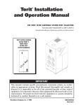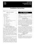
1
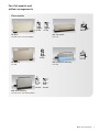
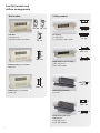
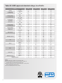
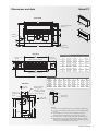
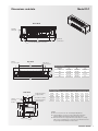
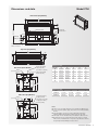
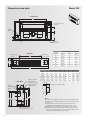
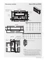
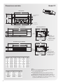
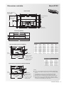
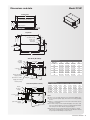
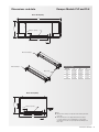
Room Fan Coil Installation, Operation and Maintenance Heating Cooling Fresh Air Clean Air i Models and arrangements 1 Ratings3 Dimensions and data 5 General information 19 Safety considerations 19 Receiving20 Unpacking and preparation 21 Handling and installation 22 Chilled/hot water connections 23 Ductwork connections 24 Electrical connections 25 Wiring diagram 26 Exposed unit touch-up 28 Start-up28 Air system balancing 29 Cooling/heating system 29 EC Motor 30 Control cards 30 Controls operation 30 Water system balancing 31 Water treatment 31 Normal operation/maintenance 32 Replacement parts 34 Equipment start-up checklist 34 IMPORTANT: Submittal documentation, specific to each project, supersedes the general guidelines contained within this manual. Fan Coil models and airflow arrangements Floor models FF-200 FF-220 FF: Floor FF-200 shown, FF-220 available FLF-510 FLF: Low profile FLF-510 FS-200 FLH-520 FLH: Low profile hideaway FLH-520 FS: Sloped FS-200 FFH-450 FFH-460 FFH: Floor hideaway FF-450 shown, FFH-460 available Models and arrangements 1 Fan Coil models and airflow arrangements Wall models Ceiling models FC - 360 FW - 260 FW - 270 FC - 370 FW: Wall FW-280 shown FW-260 and FW-270 available FW - 280 FC: Ceiling FC-360 shown FC-370 and FC-400 available FC - 400 FFRC - 410 FRW - 320 FFRC: Fully recessed ceiling FFRC-410 shown FFRC-430 available FRW: Partially recessed wall FRW-320 FFRC - 430 FCH - 470 FFRW - 340 FFRW: Fully recessed wall FFRW-340 FCH: Ceiling hideaway FCH-470 FCHP - 480 FCHP: Ceiling hideaway with plenum FCHP-500 shown FCHP-480 available 2 FCHP - 500 Table A1: AHRI approved standard ratings Unit size Certified cooling ratings (3 row main coil) Heating capacity (3 row main coil) Certified cooling ratings (4 row main coil) Heating capacity (4 row main coil) Heating capacity (optional 1 row reheat coil) 04 06 08 10 12 Total MBH 02 5.5 7.2 12.0 15.1 19.9 25.7 31.6 Sensible MBH 4.0 4.9 8.9 10.9 14.4 20.1 24.6 GPM 1.1 1.4 2.3 3.0 4.3 5.2 6.4 PD, ft. of H2O 2.8 4.9 14.4 5.2 11.0 8.1 12.8 MBH 18.7 24.5 42.3 56.6 73.4 88.8 99.9 GPM 2.0 2.6 4.7 6.7 8.9 10.2 11.3 PD, ft. of H2O 9.3 16.6 11.9 26.3 21.2 19.0 24.4 Total MBH 6.4 8.4 13.3 18.7 24.4 28.2 32.8 Sensible MBH 4.1 5.6 9.6 13.8 18.6 20.6 25.0 GPM 1.3 1.7 2.5 3.6 4.8 5.7 6.6 PD, ft. of H2O 4.6 9.9 4.4 10.0 7.7 7.1 9.9 MBH 19.9 25.5 46.3 65.8 87.0 99.2 110.9 GPM 1.9 2.5 4.3 5.8 7.5 9.1 10.2 PD, ft. of H2O 6.2 11.8 35.8 15.2 26.1 20.2 26.7 MBH 7.4 10.5 16.9 25.1 31.8 37.3 43.2 GPM 0.8 1.1 1.7 2.6 3.2 3.8 4.4 PD, ft. of H2O 0.1 0.2 0.5 1.1 1.8 2.6 3.5 High 180 230 440 625 860 1000 1190 Medium 145 160 325 360 650 675 900 Low 115 130 235 250 335 475 500 High 350 400 570 660 1000 1160 1210 Medium 320 370 530 600 910 1100 1130 Low 280 330 430 520 780 950 970 FPI 12 12 12 12 12 12 12 Face area, ft2 0.94 1.25 1.56 2.19 2.50 2.92 3.44 Coil connections 1/2" Cu 1/2" Cu 1/2" Cu 1/2" Cu 1/2" Cu 1/2" Cu 1/2" Cu Quantity 1 1 2 2 1, 2 4 4 Diameter 5.7" 5.7" 5.7" 5.7" 5.7" 5.7" 5.7" 10.4" CFM: standard CFM: high static (@ 0.2" ESP) Coil Blower Filter Cabinet size Minimum free area 03 Width 7.5" 10.4" 7.5" 10.4" 7.5", 10.4" 7.5" Number 1 1 1 1 1 1 1 Length, in. 22 28 34 46 52 60 70 9.75 Width, in. 9.75 9.75 9.75 9.75 9.75 9.75 Thickness, in. 1 1 1 1 1 1 1 Height, in. 26.5 26.5 26.5 26.5 26.5 26.5 26.5 Length, in. 38.2 44.2 50.2 62.2 68.2 76.2 86.2 Width, in. 10 10 10 10 10 10 10 Inlet, in2 99 126 153 207 234 270 315 Outlet, in2 92 110 129 184 220 257 294 90 105 120 145 160 175 200 Shipping weight, lbs. Notes: Airflow under dry conditions. Inlet air 70-80 °F DB Cooling capacity based on inlet air 80 °F DB, 67 °F WB, 45 °F entering water, 55 °F leaving water, high fan speed Heating capacity based on inlet air 60 °F DB, 180 °F entering water, 160 °F leaving water, high fan speed Pressure drop (PD) shown in feet of water Overall length for fully and partially recessed units is (length + 3"). Wall rough-in hole dimension to be (length + 1/8") by 24-1/8" width. Height dimension applies to floor units only. Wall and ceiling units are 24". Sloped top units are 29-1/4". All units supplied with replaceable filter with the exception of model FCH Model FF and FS filters are 7.25" width. Model FCHP filters are (filter length - 3-7/8") by 11" width. Models FFH, FCH, FCHP 4 row total MBH should be multiplied by 0.93 Ratings 3 Table A2: AHRI approved standard ratings, Low Profile Unit size Certified cooling ratings (2 row main coil) Heating capacity (2 row main coil) Cooling ratings (3 row high capacity coil) Heating capacity (3 row main coil) Heating capacity (optional 1 row heating coil) 02 03 04 06 Total MBH 3.5 7.1 9.8 12.6 Sensible MBH 3.0 5.2 7.3 9.3 GPM 0.8 1.4 2.0 2.3 PD, ft. of H2O 0.4 0.8 1.7 2.5 MBH 18.0 27.1 35.4 54.0 GPM 1.9 2.8 3.7 5.6 PD, ft. of H2O 1.0 2.3 4.2 10.8 Total MBH 5.2 9.6 13.3 17.2 Sensible MBH 3.7 6.4 8.9 12.2 GPM 1.2 2.0 2.7 3.6 PD, ft. of H2O 0.7 2.0 4.2 8.2 MBH 19.8 29.9 39.6 60.1 GPM 2.0 3.1 4.1 5.0 PD, ft. of H2O 1.5 3.7 6.9 12.1 MBH 11.4 17.2 23.1 35.3 GPM 1.2 1.8 2.4 3.7 PD, ft. of H2O 0.3 0.6 1.2 3.2 High 200 290 390 580 Medium 150 170 290 325 Low 100 120 150 220 High 275 390 480 680 Medium 260 375 460 625 Low 240 350 400 520 FPI 12 12 12 12 Face area, ft2 1.25 1.67 2.08 2.92 Coil connections 1/2" Cu 1/2" Cu 1/2" Cu 1/2" Cu Quantity 1 1 2 2 Diameter 5.7" 5.7" 5.7" 5.7" 10.4" CFM: standard CFM: high capacity Coil Blower Filter Cabinet size Minimum free area Width 7.5" 10.4" 7.5" Number 1 1 1 1 Length, in. 21.75 27.75 33.75 45.75 8.25 Width, in. 8.25 8.25 8.25 Thickness, in. 1 1 1 1 Height, in. 15.5 15.5 15.5 15.5 Length, in. 38.2 44.2 50.2 62.2 Width, in. 12.5 12.5 12.5 12.5 Inlet, in2 67 86 105 144 Outlet, in2 92 110 129 184 75 90 110 130 Shipping weight, lbs. Notes: Airflow under dry conditions. Inlet air 70-80 °F DB Cooling capacity based on inlet air 80 °F DB, 67 °F WB, 45 °F entering water, 55 °F leaving water, high fan speed Heating capacity based on inlet air 60 °F DB, 180 °F entering water, 160 °F leaving water, high fan speed Pressure drop (PD) shown in feet of water 4 Dimensions and data Model FF Front View C FF-200 3/8" mounting holes (4 places) 7" Drain pan pitch 11-15/16" Auxiliary drain pan 6" 1/2" NPT auxiliary drain connection FF-220 Note: inlet grill optional 8" 8" B Electrical junction box Top View Fan speed access section Unit size A B C D 02 38-3/16 22-3/16 24 20-3/4 03 44-3/16 28-3/16 30 25 04 50-3/16 34-3/16 36 29-1/4 06 62-3/16 46-3/16 48 42 08 68-3/16 52-3/16 54 51-1/8 10 76-3/16 60-3/16 62 59 12 86-3/16 70-3/16 72 69 6-1/2" 10" Dimensional data D FF-200 only (Outlet opening centered) Piping access section D FF-220 only (Outlet opening centered) A Dimensional data Side View Top outlet FF-200 only Return (hot water) Supply (steam) Supply (hot water) Return (steam) H Side outlet FF-220 only 3-1/2" E J L G M 26-7/16" K 5-11/16" E F G H J K L M N/A N/A N/A N/A 18-9/16 3 19-7/8 4-5/8 N/A 4 Row N/A N/A N/A 18-9/16 3 19-7/8 4-5/8 3/1 Row 18 7-3/4 21-3/4 4-5/16 18-9/16 3 19-7/8 4-5/8 4/1 Row 19-3/8 8-1/16 23-1/8 5-1/4 3 19-7/8 4-5/8 18-9/16 (Hot water or steam) F Supply (Cooling) Return Coil 3 Row Filter position 2-5/16" 6-1/2" Front louvers FF-220 only Notes: 3 and 4 row coil supply and return 1/2" nominal (5/8" OD) all sizes. 1 row coil (reheat option) supply and return 1/2" nominal (5/8" OD) all sizes. Left hand piping connections shown, right hand electrical as standard. Piping hand determined when facing the air outlet. Unit length: for 6" extended end pocket add 6" to dimension “A.” All listed dimensions are approximate and are subject to change without notice. Modifications to the product specifications must be accepted by Zehnder Rittling at its base office. Dimensions and data 5 Dimensions and data Model FS Front View C 3/8" mounting holes (4 places) 7" Drain pan pitch 11-15/16" Auxiliary drain pan 6" 1/2" NPT auxiliary drain connection Note: Inlet grill optional B 8" Top View Piping access section D (Outlet opening centered) Fan speed access section Dimensional data Unit size A B C D 02 38-3/16 22-3/16 24 20-3/4 03 44-3/16 28-3/16 30 25 04 50-3/16 34-3/16 36 29-1/4 06 62-3/16 46-3/16 48 42 08 68-3/16 52-3/16 54 51-1/8 10 76-3/16 60-3/16 62 59 12 86-3/16 70-3/16 72 69 6-1/2" 10" Electrical junction box 8" A Side View Return (hot water) Supply (steam) F H (Hot water or steam) Supply (Cooling) Return Supply (hot water) Return (steam) Coil E F G H J K L M 3 Row N/A N/A N/A N/A 18-9/16 3 19-7/8 4-5/8 4 Row N/A N/A N/A N/A 18-9/16 3 19-7/8 4-5/8 3/1 Row 18 7-3/4 21-3/4 4-15/16 18-9/16 3 19-7/8 4-5/8 3 19-7/8 4-5/8 4/1 Row 19-3/8 8-1/16 23-1/8 K 5-1/4 18-9/16 G 3-1/2" E J L 29-1/4" M 5-11/16" Filter position 6 Dimensional data Notes: 3 and 4 row coil supply and return 1/2" nominal (5/8" OD) all sizes. 1 row coil (reheat option) supply and return 1/2" nominal (5/8" OD) all sizes. Left hand piping connections shown, right hand electrical as standard. Piping hand determined when facing the air outlet. Unit length: for 6" extended end pocket add 6" to dimension “A.” All listed dimensions are approximate and are subject to change without notice. Modifications to the product specifications must be accepted by Zehnder Rittling at its base office. Dimensions and data Model FLF 2-7/16" Auxiliary drain pan 15-1/2" Front View 3-5/16" 8" Note: Inlet grill standard B 8" Electrical junction box 1/2" NPT auxiliary drain connection Fan speed access section Dimensional data 6-1/2" C (Outlet opening centered) Unit size A B C 02 38-3/16 22-3/16 20-3/4 12-1/2" Top View Piping access section 03 44-3/16 28-3/16 25 04 50-3/16 34-3/16 29-1/4 06 62-3/16 46-3/16 42 A Dimensional data Side View Supply (Cooling) Return G J E Return (hot water) Supply (steam) Coil D E F G H J K 3 row N/A N/A N/A N/A 10-3/8 5-1/2 11-1/2 4 row N/A N/A N/A N/A 10-3/8 5-9/16 12-5/8 (Hot water or steam) 3/1 row 12-9/16 9-1/8 12-7/8 2-1/16 10-3/8 5-1/2 11-1/2 Supply (hot water) Return (steam) 4/1 row 13-11/16 9-1/8 14 2-1/8 10-3/8 5-9/16 12-5/8 H K D F Drain pan pitch 6-7/8" Filter position Notes: All coil connections are 1/2" nominal (5/8" OD) all sizes Left hand piping connections shown, right hand electrical as standard. Piping hand determined when facing air outlet. All listed dimensions are approximate and are subject to change without notice. Modifications to the product specifications must be accepted by Zehnder Rittling at its base office. Dimensions and data 7 Dimensions and data Model FLH Front view 11/16" Electrical junction box Auxiliary drain pan 2-1/8" 4" 5-1/16" 6-5/8" Inlet opening 15-9/16" B (Outlet opening centered) 3-5/16" 2-7/16" A 1/2" NPT auxiliary drain connection Top view 9/16" Dimensional data 12-1/2" 4" 5" outlet opening Unit size A B 02 22-5/16 16-3/16 03 28-5/16 22-3/16 04 34-5/16 28-3/16 06 46-5/16 40-3/16 Side view D H Supply F (Cooling) Return Return (hot water) Supply (steam) (Hot water or steam) Supply (hot water) Return (steam) Dimensional data C G E J Drain pan pitch 7-1/8" Coil C D E F G H J 2 Row N/A N/A N/A N/A 10-9/16 5-1/2 11-5/8 3 Row N/A 12-13/16 N/A N/A N/A 10-5/8 5-9/16 2/1 Row 12-11/16 9-1/16 13-1/16 2 10-9/16 5-1/2 11-5/8 3/1 Row 13-13/16 9-1/8 14-3/16 2-1/16 10-5/8 5-9/16 12-13/16 Filter position Notes: All coil connections are 1/2" nominal (5/8" OD) all sizes Left hand piping connections shown, right hand electrical as standard. Piping hand determined when facing the air outlet. All listed dimensions are approximate and are subject to change without notice. Modifications to the product specifications must be accepted by Zehnder Rittling at its base office. 8 Dimensions and data Model FFH Front View (Top Outlet) 4-1/2" C E (Outlet opening centered) Electrical junction box 6-5/8" 3-5/16" Auxiliary drain pan 4" 18-5/8" 23-15/16" Drain pan pitch 6-3/4" 4-1/8" D (Inlet opening centered) 2-1/4" B 1/2" NPT auxiliary drain connection Top View (Top Outlet) E (Opening centered) Outlet opening 6" 9-7/8" 4" 5/8" A Return (hot water) Supply (steam) Side View (Front Outlet) (Hot water or steam) Supply Return 6" 1-1/8" H 3-1/16" J 4-1/16" 3-1/2" (Inlet opening) G 23-15/16" 17-5/16" 16" 4-13/16" Supply (hot water) Return (steam) 4-3/4" A B C D E 02 24-1/8 22-3/8 24 21 18 03 30-1/8 28-3/8 30 27 24 04 36-1/8 34-3/8 36 33 30 06 48-1/8 46-3/8 48 45 42 08 54-1/8 52-3/8 54 51 48 10 62-1/8 60-3/8 62 59 56 12 72-1/8 70-3/8 72 69 66 Dimensional data Filter position 1" Side View (Top Outlet) 6" 2" 23-15/16" 17-5/16" 16" 4-1/16" 3-1/16" Filter position Coil F G H J 3/1 Row 19-3/16 15-7/16 4-15/16 7-3/4 4/1 Row 20-9/16 16-13/16 5-1/4 8-1/16 (Hot water or steam) Supply (hot water) Return (steam) H 4-13/16" 4-3/4" Return (hot water) Supply (steam) 3-1/2" (Inlet opening) G F Supply (Cooling) Return Unit size F (Cooling) Dimensional data Notes: 3 and 4 row coil supply and return 1/2" nominal (5/8" OD) all sizes. 1 row coil (reheat option) supply and return 1/2" nominal (5/8" OD) all sizes. Left hand piping connections shown, right hand electrical as standard. Piping hand determined when facing the air outlet. Unit length: For 6" extended end pocket add 6" to dimension “A.” All listed dimensions are approximate and are subject to change without notice. Modifications to the product specifications must be accepted by Zehnder Rittling at its base office. Dimensions and data 9 Dimensions and data Model FW Front View B 3/8" mounting holes (4 places) 9-7/16" 3-1/2" 7" Drain pan pitch Auxiliary drain pan 1/2" NPT auxiliary drain connection Electrical junction box Dimensional data Top View C (Outlet opening centered) Fan speed access section 6-1/2" 10" Piping access section Unit size A B C 02 38-3/16 24 20-3/4 03 44-3/16 30 25 04 50-3/16 36 29-1/4 06 62-3/16 48 42 08 68-3/16 54 51-1/8 10 76-3/16 62 59 12 86-3/16 72 69 A Dimensional data Coil D E F G H J K L 3 Row N/A N/A N/A N/A 16-1/8 3 17-3/8 4-5/8 4 Row N/A N/A N/A 16-1/8 3 17-3/8 4-5/8 19-5/16 4-15/16 16-1/8 3 17-3/8 4-5/8 3 17-3/8 4-5/8 3/1 Row 15-9/16 Return (hot water) Supply (steam) Side View (Hot water or steam) Supply (hot water) Return (steam) E Supply (Cooling) Return G N/A 7-3/4 4/1 Row 16-15/16 8-1/16 20-11/16 5-1/4 16-1/8 2-5/16" (top), 2-7/16" (bottom) 6-1/2" F D H K L 24" J 5-11/16" Filter position dependent on model 10 Notes: 3 and 4 row coil supply and return 1/2" nominal (5/8" OD) all sizes. 1 row coil (reheat option) supply and return 1/2" nominal (5/8" OD) all sizes. Left hand piping connections shown, right hand electrical as standard. Piping hand determined when facing the air outlet. Unit length: for 6" extended end pocket add 6" to dimension “A.” All listed dimensions are approximate and are subject to change without notice. Modifications to the product specifications must be accepted by Zehnder Rittling at its base office. Dimensions and data Models FRW and FFRW Front View Wall trim shipped loose, field mounted to desired depth C 3/8" mounting holes (4 places) 9-7/16" 3-1/2" 7" Drain pan pitch Auxiliary drain pan 8" 1/2" NPT auxiliary drain connection B Electrical junction box 8" Dimensional data Unit size A B C D E 02 38-3/16 22-3/16 24 20-3/4 41-3/16 03 44-3/16 28-3/16 30 25 47-3/16 04 50-3/16 34-3/16 36 29-1/4 53-3/16 06 62-3/16 46-3/16 48 42 65-3/16 08 68-3/16 52-3/16 54 51-1/8 71-3/16 10 76-3/16 60-3/16 62 59 79-3/16 12 86-3/16 70-3/16 72 69 89-3/16 Top View A Fan speed access section 10" Piping access section D (Outlet opening centered) E Dimensional data Side View F G H J K L M N N/A N/A N/A N/A 16-1/8 3 17-3/8 4-5/8 4 Row N/A N/A N/A 16-1/8 3 17-3/8 4-5/8 19-5/16 4-15/16 16-1/8 3 17-3/8 4-5/8 3 17-3/8 4-5/8 N/A Return (hot water) Supply (steam) 3/1 Row 15-9/16 (Hot water or steam) 4/1 Row 16-15/16 8-1/16 20-11/16 7-3/4 5-1/4 16-1/8 Supply (hot water) Return (steam) G Supply (Cooling) Coil 3 Row J 2-5/16" (top), 2-7/16" (bottom) Return 6-1/2" L 27" 24" H 5-11/16" F K M N 6-1/2" Filter position 2-7/16" Notes: 3 and 4 row coil supply and return 1/2" nominal (5/8" OD) all sizes. 1 row coil (reheat option) supply and return 1/2" nominal (5/8" OD) all sizes. Left hand piping connections shown, right hand electrical as standard. Piping hand determined when facing the air outlet. Unit length: For 6" extended end pocket add 6" to dimension “A.” All listed dimensions are approximate and are subject to change without notice. Modifications to the product specifications must be accepted by Zehnder Rittling at its base office. Dimensions and data 11 Dimensions and data Model FC Bottom View C Drain pan 3/8" mounting holes (4 places) 24" 7" 7/8" OD x 2" LG “plain end” connection 9-7/16" 13-1/2" 2-3/4" B 8" Electrical junction box Front View (Ducted Outlet) Side View (with Duct) A Electrical section Filter position F Supply (Cooling) Return 1-15/16" 10" 5-1/8" Piping section G 1" 4-5/16" 24" E (Outlet opening centered) 2-1/16" Drain pan pitch 6-5/8" 8" Drain pan pitch Return (hot water) Supply (steam) (Hot water or steam) Remo vable h with safety inged do or lanya rd Supply (hot water) Return (steam) 21-3/8" Front View (Louvered Outlet) Side View (with Louver) A Electrical section Drain pan pitch Filter position dependent on model Supply (Cooling) Return 6-5/8" Piping section F G 1-15/16" 6-1/2" D (Outlet opening centered) 4-5/16" 24" Drain pan pitch Remo vable h with safety inged do or lanya rd 21-3/8" Return (hot water) Supply (steam) (Hot water or steam) Supply (hot water) Return (steam) Dimensional data Unit size A B C D E 02 38-3/16 22-3/16 24 20-3/4 18-3/16 03 44-3/16 28-3/16 30 25 24-3/16 04 50-3/16 34-3/16 36 29-1/4 30-3/16 06 62-3/16 46-3/16 48 42 42-3/16 08 68-3/16 52-3/16 54 51-1/8 48-3/16 10 76-3/16 60-3/16 62 59 56-3/16 12 86-3/16 70-3/16 72 69 66-3/16 Dimensional data 12 Coil F G 3 Row 20-1/8 17-15/16 4 Row 18-15/16 16-13/16 3/1 Row 20-1/8 17-15/16 4/1 Row 18-15/16 16-13/16 Notes: 3 and 4 row coil supply and return 1/2" nominal (5/8"OD) all sizes. 1 row coil (reheat option) supply and return 1/2" nominal (5/8" OD) all sizes. Left hand piping connections shown, right hand electrical as standard. Piping hand determined when facing the air outlet. Unit length: For 6" extended end pocket add 6" to dimension “A.” All listed dimensions are approximate and are subject to change without notice. Modifications to the product specifications must be accepted by Zehnder Rittling at its base office. Dimensions and data Model FFRC Bottom View Wall trim shipped loose, field mounted to desired depth C 3/8" mounting holes (4 places) 7" 24" Drain pan 7/8" OD x 2" Lg. “plain ended” connection 9-7/16" 13-1/2" 2-3/4" 8" B Electrical junction box 8" Front View (Outlet) A D (Outlet opening centered) 10" 5-1/8" Piping section Electrical section Drain pan pitch E Dimensional data Side View (Ducted Inlet and Outlet) 1" 6-5/8" F G Supply (Cooling) Return 2-1/16" 1-15/16" Filter position 24" 4-5/16" 1" Drain pan pitch Remo va with s ble hinged afety lanya door rd 21-3/8" (Hot water or steam) Filter position 6-5/8" Supply (Cooling) Return 2-1/16" 1-15/16" F Drain pan pitch Remo vable hinge with safet y lany d door a rd 21-3/8" B C D E 38-3/16 22-3/16 24 18-3/16 41-3/16 03 44-3/16 28-3/16 30 24-3/16 47-3/16 04 50-3/16 34-3/16 36 30-3/16 53-3/16 06 62-3/16 46-3/16 48 42-3/16 65-3/16 08 68-3/16 52-3/16 54 48-3/16 71-3/16 10 76-3/16 60-3/16 62 56-3/16 79-3/16 12 86-3/16 70-3/16 72 66-3/16 89-3/16 Dimensional data Coil F G 3 Row 20-1/8 17-15/16 4 Row 18-15/16 16-13/16 3/1 Row 20-1/8 17-15/16 4/1 Row 18-15/16 16-13/16 4-5/16" Side View (Louvered Inlet and Ducted Outlet) G A 02 Return (hot water) Supply (steam) Supply (hot water) Return (steam) 24" Unit size Return (hot water) Supply (steam) (Hot water or steam) Supply (hot water) Return (steam) Notes: 3 and 4 row coil supply and return 1/2" nominal (5/8" OD) all sizes. 1 row coil (reheat option) supply and return 1/2" nominal (5/8" OD) all sizes. Left hand piping connections shown, right hand electrical as standard. Piping hand determined when facing the air outlet. Unit length: For 6" extended end pocket add 6" to dimension “A.” All listed dimensions are approximate and are subject to change without notice. Modifications to the product specifications must be accepted by Zehnder Rittling at its base office. Dimensions and data 13 Dimensions and data Model FCH Front View A 9-7/8" 10-1/16" B (Outlet opening centered) Drain pan pitch Top View Remote junction box 6-3/16" 1" 7/8" OD x 2" LG “plain end” connection 3/4" Drain pan 3/4" 10-3/8" 6-11/16" 1-1/8" Flexible plastic conduit 1-1/4" C D Dimensional data A B C D 02 21-5/8 18-3/16 20-3/16 28 03 27-5/8 24-3/16 26-3/16 34 Side View 04 33-5/8 30-3/16 32-3/16 40 17-7/8" 06 45-5/8 42-3/16 44-3/16 52 08 51-5/8 48-3/16 50-3/16 58 10 59-5/8 56-3/16 58-3/16 66 12 69-5/8 66-3/16 68-3/16 76 2-3/16" E Supply (Cooling) Return 1-1/8" 6-1/2" 1-13/16" 4-3/16" 2-1/2" 10-1/16" piping end Unit size 7-15/16" outlet opening Dimensional data Coil E 3 Row 4-5/8 4 Row 5-11/16 Return (hot water) Supply (steam) 3/1 Row 6 (Hot water or steam) 4/1 Row 7-1/16 Supply (hot water) Return (steam) Notes: 3 and 4 row coil supply and return 1/2" nominal (5/8" OD) all sizes. 1 row coil (reheat option) supply and return 1/2" nominal (5/8" OD) all sizes. Add 2" to overall length dimension when electric heat option is included. Front view and top view show right hand piping connections. Side view shows left hand piping connections. Piping hand determined when facing the air outlet. Electrical opposite piping. All listed dimensions are approximate and are subject to change without notice. Modifications to the product specifications must be accepted by Zehnder Rittling at its base office. 14 Dimensions and data Model FCHP Front View 9-5/8" 11-1/8" A B Supply and return (outlet opening centered) Drain pan pitch 3/4" 7/8" OD x 2" LG “plain end” connection Drain pan 1-13/16" 11-7/16" Top View 6-3/16" 1" 10-5/16" 3/4" 6-11/16" 1-1/4" 3/4" C D Side View (End Inlet) Return (Cooling) Supply E 11-1/8" 6-1/2" Return (hot water) Supply (steam) Dimensional data 4-3/16" 1-13/16" 7-15/16" outlet opening 21-11/16" G F 1-1/8" Drain pan Supply (hot water) Return (steam) C D 18-3/16 20-3/16 28 03 27-11/16 24-3/16 26-3/16 34 04 33-11/16 30-3/16 32-3/16 40 06 45-11/16 42-3/16 44-3/16 52 08 51-11/16 48-3/16 50-3/16 58 10 59-11/16 56-3/16 58-3/16 66 12 69-11/16 66-3/16 68-3/16 76 Dimensional data Return (Cooling) Supply 21-11/16" K J H Coil E F G H J K 3 Row 17-1/16 19-1/4 N/A 17-1/8 19-5/16 N/A 4 Row N/A 16-1/16 18-1/4 N/A 16-1/8 18-5/16 3/1 Row 15-11/16 17-7/8 19-1/4 15-3/4 17-15/16 19-15/16 4/1 Row 14-11/16 16-7/8 19-1/4 14-3/4 16-15/16 19-15/16 4-3/16" 11-1/8" 1-13/16" 6-1/2" B 21-11/16 Filter position Side View (Bottom Inlet) Return (Hot water reheat) Supply A 02 1-3/4" (Hot water or steam) 7-15/16" outlet opening Unit size 1-1/8" 1-3/4" Filter position Drain pan Notes: 3 and 4 row coil supply and return 1/2" nominal (5/8" OD) all sizes. 1 row coil (reheat option) supply and return 1/2" nominal (5/8" OD) all sizes. Add 2" to overall length and coil connection location when electric heat option is included. Front view and top view show right hand piping connections. Side view shows left hand piping connections. Piping hand determined when facing the air outlet. Electrical opposite piping. All listed dimensions are approximate and are subject to change without notice. Modifications to the product specifications must be accepted by Zehnder Rittling at its base office. Dimensions and data 15 Dimensions and data Damper Models FF, FS and FFH Front view (FF and FS) A C 3/8" mounting holes (4 places) 29-1/4" (Slope top unit) 7" 26-1/2" Damper opening 1-7/8" 11-15/16" D 3/8" Motorized damper Dimensional data Manual damper Motor end Unit size A B C D 02 38-3/16 22-3/8 24 18-5/8 03 44-3/16 28-3/8 30 18-5/8 04 50-3/16 34-3/8 36 23-5/8 06 62-3/16 46-3/8 48 23-5/8 08 68-3/16 52-3/8 54 33-5/8 10 76-3/16 60-3/8 62 33-5/8 12 86-3/16 70-3/8 72 33-5/8 Front view (FFH) 23-15/16" Damper opening 1-7/8" D 3/8" B 16 Notes: Damper motor always on right side when viewing unit from front side. All listed dimensions are approximate and are subject to change without notice. Modifications to the product specifications must be accepted by Zehnder Rittling at its base office. Dimensions and data Damper Models FLF and FLH Back View (FLF) 15-1/2" A Damper opening 1-7/8" C 11/16" Motorized damper Manual damper Dimensional data Motor end Unit size A B C 02 38-3/16 22-5/16 18-5/8 03 44-3/16 28-5/16 18-5/8 04 50-3/16 34-5/16 23-5/8 06 62-3/16 46-5/16 33-5/8 15-1/2" Back View (FLH) Damper opening 1-7/8" C B 11/16" Notes: Damper motor always on right side when viewing unit from front side. All listed dimensions are approximate and are subject to change without notice. Modifications to the product specifications must be accepted by Zehnder Rittling at its base office. Dimensions and data 17 Dimensions and data Outside air wall box Telescoping inner and outer aluminum box Unpainted aluminum louvered inlet grille with internal bug screen 4" to 8" 1/2" Dimensional data 2 5/8" 2 13/16" Model A Rough opening WB-0203 24 22-1/2 x 3 WB-0406 29 27-1/2 x 3 WB-081012 39 37-1/2 x 3 Side View A 3 1/2" Front View 18 Weep holes General information This installation and start-up instructions literature is for horizontal and vertical Room Fan Coils. Fan coils are hydronic terminal units designed for year-round cooling or cooling/heating. Your equipment is initially protected under the Zehnder Rittling standard 2-year warranty provided the steps outlined in this manual for initial inspection, installation, periodic maintenance and normal every day operation of the equipment are followed. This manual should be thoroughly reviewed prior to the installation, start-up or maintenance of the equipment. If any questions arise, please contact your local Zehnder Rittling sales representative or the factory before proceeding any further. There are a multitude of options and accessories available with the equipment covered in this manual. For more specific details on the included options and accessories, refer to the order acknowledgment, approved submittals and catalogs. Safety considerations The installation of Room Fan Coil units and all associated components, parts and accessories which make up the installation, shall be in accordance with the regulations of all authorities having jurisdiction and must conform to all applicable codes. Only trained and qualified service personnel using good judgment and safe practices should install, repair and/or service air conditioning equipment. Untrained personnel can perform basic maintenance functions such as cleaning coils and cleaning or replacing filters. All other operations should be performed by trained service personnel. When working on air conditioning equipment, observe precautions in the literature, tags and labels attached to the equipment and all other safety precautions that may apply. Improper installation, adjustment, alteration, service, maintenance, or use can cause explosion, fire, electrical shock or other hazardous conditions which may cause serious personal injury and/or property damage. Consult a qualified installer, service agency, or your sales representative for information or assistance. The equipment must always be properly supported by rigging and lifting equipment. Any temporary supports used during installation or maintenance must be designed to adequately hold the equipment in place until equipment is permanently fastened and set in its final location. All supports must meet applicable local codes and ordinances. All fastening devices must be designed to mechanically hold the assembly in place without the ability to loosen or break away due to system operation or vibration. All power must be disconnected and locked out before any installation or service is performed to avoid electrocution or shock. More than one power source may be supplied to a unit. Power to remote mounted units may not be supplied through the unit. Electric resistance heating elements must be disconnected prior to servicing to avoid burns. Never use bulky or loose fitting clothing when working on any mechanical equipment. Gloves should always be worn for protection against heat, sharp edges and all other possible hazards. Safety glasses should always be worn, especially when drilling, cutting or working with chemicals. Never pressurize equipment beyond specified pressures as shown on unit rating plate. Always pressure test with an inert fluid such as water or dry nitrogen to avoid possible damage or injury in the event of a leak or component failure during testing. Always protect adjacent flammable material when welding or soldering. Use a suitable heat shield material to contain sparks or drops of solder. Have a fire extinguisher readily available. Please follow standard safe practices regarding the handling, installing or servicing of mechanical equipment. General information 19 Safety considerations Read these instructions thoroughly and follow all warnings or cautions attached to the equipment. Consult local building codes and the National Electrical Code(NEC) for special installation requirements. Understand the signal words: danger, warning and caution. Identifies the most serious hazards which will result in severe personal injury or death. Signifies hazards that could result in personal injury or death. Used to identify unsafe practices, which would result in minor personal injury or product and property damage. The manufacturer assumes no responsibility for personal injury or property damage resulting from improper or unsafe practices during the handling, installation, service or operation of the equipment. The installation of fan coils and all associated components, parts and accessories shall be in accordance with the regulations of all authorities having jurisdiction and must conform to all applicable codes. It is the responsibility of the installing contractor to determine and comply with all applicable codes and regulations. Receiving Upon delivery, examine the shipment against the bill of lading to make sure all of the units have been received and then check each unit carefully for shipping damage. Any damage should be reported to the freight carrier and a claim should be filed with them. Ensure the shipping company makes proper notation of any shortages or damage on all copies of the freight bill. Concealed damage not discovered during unloading must be reported to the shipping company within 15 days of receipt of the shipment. All units are shipped F.O.B. factory. Therefore, Zehnder Rittling is not responsible for damage during transit. It is the responsibility of the installing 20 contractor to inspect and verify that the units shipped were in fact the correct model number, voltage, etc. Any discrepancies should be reported to the local Sales Representative for immediate resolution prior to unpackaging and installation. The factory should be notified of any warranty repairs required in writing before any corrective action is taken. The factory must be fully informed of the expected costs before the work is begun. Zehnder Rittling is not responsible for any repairs or alterations made by the purchaser without Zehnder Rittling’s written consent and will not accept any back charges associated with these repairs or alterations. The return of damaged equipment will not be accepted without written authorization from Zehnder Rittling. A unit that has received a written Return Goods Authorization will be inspected by Zehnder Rittling upon receipt. Any damage, missing parts, reworking or repackaging resulting from prior installation will constitute just cause for Zehnder Rittling to issue partial credit. Several components are shipped loose for field installation and to offer added protection during shipment and job site storage. These items may include; thermostat, valve packages, remote temp sensors, etc. Unpacking and preparation All units are carefully inspected at the factory throughout the entire fabrication and assembly processes under Zehnder Rittling’s stringent quality assurance program. All major components and subassemblies such as motors, blowers, coils, controls, valve packages and paint quality are carefully tested for proper operation, visually inspected and verified for full compliance with factory standards. Operational testing for some customer furnished components such as pneumatic valves and DDC controllers may be a possible exception. Room Fan Coils are usually shipped on pallets of up to 5 units. Each unit is factory tagged according to the customer’s purchase order. This allows the unit, upon removal from the pallet, to be taken directly to its’ assigned space for immediate installation. Units should not be installed at locations other than that designated on the tag. Each unit is carefully packaged in a polyethylene plastic bag for surface protection, placed in a cardboard container and filled with kraft paper padding for shipment to avoid damage during normal handling in the shipment process. It is the sole responsibility of the customer to provide the protection necessary to prevent vandalism and weather deterioration of the equipment. Under no condition should the units be left unprotected from the elements. If the equipment is not needed immediately at the job site, it should be left in its shipping carton and stored in a clean, dry area of the building or in a warehouse. Do not remove any equipment from its shipping package until it is needed for installation. The equipment is NOT suitable for outdoor installations. After determining the condition of the cardboard container exterior, carefully remove each unit from the container and inspect for hidden damage. At this time, check that all shipped loose items such as wall mounted thermostats, changeover switches, remote temperature sensors, auxiliary drain pans, valve packages, etc. are accounted for and placed in a safe area. Any hidden damage should be recorded and immediately reported to the carrier and a claim should be filed. In the event a claim for shipping damage is filed, the unit, cardboard container, and all packing must be kept for physical inspection by the freight carrier. components. All manufacturer’s warranties are void if foreign material is allowed to be deposited in the drain pan or on the motor or blower wheels of any unit. Some job conditions may require some form of temporary unit covering during construction. DO NOT store or install units in corrosive environments or in locations subject to temperature or humidity extremes (e.g., attics, garages, rooftops, etc.). Corrosive conditions and high temperature or humidity can significantly reduce system performance, reliability and overall service life. Once the equipment is properly positioned on the job site, cover the units with either a shipping carton, vinyl film, or an equivalent protective covering. Cap open ends of piping that is stored on a job site. Take special care to prevent foreign materials from entering the units in areas where painting, dry walling, or spraying of fireproof material, etc. has not yet been completed as these materials may accumulate in the drain pan or on the motors and blower wheels. Foreign material that accumulates within the units can prevent proper start-up, necessitate costly clean-up operations, or result in immediate or premature component failure. Before installing any of the system components, be sure to examine each pipe, fitting and valve, and remove any dirt or foreign material found in or on these Unpacking and preparation 21 Handling and installation While all equipment is designed for durability and fabricated with heavy gauge materials and may present a robust appearance, great care must be taken to assure that no undue force is applied to the coil, piping, drain connection or other delicate components such as control boards during handling. Wherever possible, all units should be maintained in an upright position and handled by the chassis, plenum sections or as close as possible to the mounting points. In the case of a fully exposed cabinet unit, the unit must obviously by handled by the exterior casing. Gloves should be worn when handling finished, painted units and should never be set down on unclean, hard surfaces. Failure to follow these instructions may lead to scratching or gouging of the finished surface. Although Zehnder Rittling does not become involved with the design and selection of support methods and/or components, it should be recognized that unacceptable operating characteristics and/or performance may result from poorly implemented unit support. Additionally, proper clearance must be provided for service and removal of the equipment. Anchoring the equipment in place is accomplished by using the mounting points provided, and positioning the unit on a LEVEL plane. The drain pan is pitched within the unit to provide proper drainage when the unit is installed level. Care must be taken to ensure that the drain pan does not slope away from the drain connection. Vertical units are designed to be bolted to the wall structure through the slotted wall mounting holes in the chassis, used for anchoring to preinstalled wall studs. Horizontal units are provided with slotted ceiling mounting brackets while the hideaway ceiling units have slots in the top panels where hanging rod and rubber-in-shear or spring vibration isolators, supplied by others, can be used for proper suspension and vibration isolation. The type of mounting device is a matter of choice, however the mounting point should always be that provided in the chassis, plenum or cabinet. Improper mounting could result in the unit falling from its position, causing personal injury or even death. 22 After mounting the unit, it is then ready for the various service connections such as water, drain and electrical. At this time it should be verified that the proper types of services are actually provided to the unit. On those units requiring chilled water and/or hot water, the proper line size and water temperature should be available to the unit. On units with steam heating coils, the proper line sizing and routing should be verified. The maximum steam pressure should never exceed 15 psig. The drain piping and steam trap, supplied by others, should be sized and routed to allow for proper condensate flow. The electrical service to the unit should be compared to the unit nameplate to verify compatibility. The routing and sizing of all piping, and the type and sizing of all wiring and other electrical components such as circuit breakers, disconnect switches, etc. should be determined by the individual job requirements and should not be based on the size and/or type of connection(s) provided on the equipment. Verify the electrical conductor size is suitable for the distance to the equipment connection and will support the equipment electrical load. All installations should be made in compliance with all governing codes and ordinances. Compliance with all codes is the responsibility of the installing contractor. Chilled/hot water connections Submittals and product literature detailing unit operation, controls and connections should be thoroughly reviewed before beginning the connection of the various cooling and/or heating mediums to the unit. All shipped loose valve packages should be installed as required and all service valves should be checked for proper operation. All coil and valve package connections are to be made with a sweat or solder joint. Care should be taken to assure that no components in the valve package are subjected to a high temperature which may damage seals or other materials. Many two-position electric control valves, depending on valve operation, are provided with a manual opening lever. This lever should be placed in the “open” position during all soldering or brazing operations. In accordance with good soldering and brazing practices, valve bodies should be wrapped with a wet rag to help dissipate the heat. If the valve package connection at the coil is made with a union, the coil side of the union must be prevented from twisting during tightening to prevent damage to the coil tubing. Over-tightening must be avoided to prevent distorting the union seal surface and destroying the union, ultimately causing a leak. The inlet supply connection is marked at the appropriate coil stubout with the other coil stub-out being the outlet return connection. In the case of field installed valve packages and piping, the chilled water valve package should be installed in such a way that any dripping condensate is captured in the drain pan/auxiliary drip pan or alternatively, is eliminated through the use of insulation. Factory drip pans are field installed and may be packaged separately from the unit. Factory supplied cooling coil valve packages will be arranged over the drain pan and/or drip pan. After the connections are completed, the system should be tested for leaks. Since some components are not designed to hold pressure with a gas, hydronic systems should be tested with water. Test pressure must not exceed 250 psig. Pressure testing should be completed prior to sheet rocking, finished floors, painting, caulking, etc. All water coils must be protected from freezing after initial filling with water. Even if the system is drained, unit coils may still hold enough water to cause damage when exposed to temperatures below freezing. In the event that leaking or defective components are discovered, the Zehnder Rittling Sales Representative must be notified before any repairs are attempted. All leaks should be repaired before proceeding with the installation. After system integrity has been established, the piping should be insulated in accordance with the project specifications. This is the responsibility of the installing or the insulation contractor. Zehnder Rittling will not accept any charges associated with re-insulating piping if the installing contractor failed to establish system integrity prior to insulating. All chilled water piping and valves not located over the drain pan or drip pan must be insulated to prevent damage from sweating. This includes factory and field piping inside the unit cabinet. The condensate drain should always be connected and piped to an acceptable disposal point. For proper condensate flow, the drain piping should be sloped away from the unit at least 1/8 inch per foot. A P-trap may be required by local codes and it is strongly recommended for odor containment. Condensate drain lines should be at least the same diameter as the drain connection. Properly sized traps should be used to allow proper removal of the condensate from the drain pan. The bottom of the trap should be at least (1” + cabinet static pressure) below the drain pan connection. The top of the trap should be at least 1” below the drain connection when cabinet is under positive pressure and ½ the distance of the bottom of the trap from the drain connection when cabinet is under negative pressure. The condensate drain hose should be secured with a clamp after installing. Secure the union nut hand-tight and then tighten no more than an additional 1/4 turn. Chilled/hot water connections 23 Ductwork connections All ductwork and or supply and return grilles should be installed in accordance with the project plans and specifications. If not included on the unit or furnished from the factory, supply and return grilles should be provided as recommended in the product catalog. For units with no return air ductwork, check local code requirements for possible application restrictions. All units must be installed in noncombustible and non-hazardous areas. Some models are designed to be connected to ductwork with a minimum amount of external static pressure. These units may be damaged by operation without the proper ductwork connected. Consult the approved submittals and the product catalog for unit external static pressure limitations. Units provided with outside air should have some form of low temperature protection to prevent coil(s) from freezing. This protection may be a lowtemperature thermostat to close the outside air damper, a preheat coil to temper the outside air before it reaches the unit, or any other protective method. It should be noted that none of these methods will adequately protect a coil in the event of power failure. The safest method of freeze protection is to use glycol in the proper percent solution for the coldest expected air temperature. 24 Horizontal hideaway units with plenum can be field converted from bottom inlet to rear inlet or vice versa. Remove the filter retaining clips, filter, filter retaining C-channel and the rear/bottom return panel. Rotate the panel and C-channel to the bottom/rear mounting location leaving the 1” wide filter slot at the back or bottom of the unit. Flexible duct connections should be used on all air handling equipment to minimize vibration transmissions. Insulation and ductwork should be installed to allow servicing of equipment including motors, blowers, filters, etc. Zehnder Rittling assumes no responsibility for undesirable system operation due to improper design, equipment or component selection, and/ or installation of base unit, ductwork, grilles and other related components. Electrical connections The unit serial tag lists the unit electrical characteristics such as the required supply voltage, motor and heater amperage and required circuit ampacities. The unit wiring diagram shows all unit and field wiring. The installer must be familiar with the wiring diagram before beginning any wiring as the wiring can change from project to project. All wiring connections should be checked prior to start-up to ensure connections have not come loose during shipment or installation, minimizing problems during start-up. Electrical shock can cause personal injury or death. When installing or servicing system, always turn off main power to system. There may be more than one disconnect switch. Thermostat “OFF” should not be used for disconnect purposes. Consult the factory wiring and valve package diagrams when installing a changeover switch. The switch should always be installed upstream of the control valve on a pipe that will have constant flow regardless of the control valve position, allowing a true water temperature reading at all times. A bleed bypass may be required to guarantee proper changeover switch operation. All field wiring connecting to this type of unit must by 105 F rated copper conductor and should be in accordance with the National Electrical Code and any applicable local codes. Branch circuit fusing and electrical disconnect means, if required, must be furnished and installed by others. All unit-mounted control components and electrical heater elements, when furnished, are factory wired to the junction control box located in the electrical end pocket of painted, finished units or on the side of hideaway units. Remotemounted control components are shipped loose for field installation and wiring and are to be wired in strict accordance with the wiring diagram. Failure to do so could result in personal injury or damage to components and will void the manufacturer warranty. The fan motor(s) should never be controlled by any wiring or device other than the factory supplied switch or thermostat/ switch combination without factory authorization. The applicable wiring diagram ships with each unit and must be strictly followed. Field power supply wiring should be through end pocket openings or knockouts in the supplied junction boxes. All field wiring should be done in accordance with governing codes and ordinances. Any modification of the unit wiring without factory authorization will void the warranty and nullify any agency listings. Zehnder Rittling assumes no responsibility for any damages and/or injuries from improper field installation and/or wiring. Electrical connections 25 Wiring schematic 120V MANUAL MOTOR STARTER (OPTIONAL) PSC MOTOR (OPTION) SEE CHART RED H MOTOR QUICK CONNECT (OPTIONAL) BLUE DAMPER MOTOR M SEE CHART YELLOW BLUE T1 L BLACK L1 YELLOW T2 SEE CHART L2 BLOWER MOTOR WHITE BLUE WHITE HEATER WHITE *BROWN *BROWN TERMINATED IF NO DAMPER MOTOR (OPTIONAL) 3-SPEED SWITCH CONTROL PACKAGE (OPTIONAL) HOT 120V L2 NEUTRAL WHITE GFCI RECEPTACLE (OPTIONAL) 120V L1 HOT LINE DISCONNECT SWITCH (OPTIONAL) FREEZESTAT (OPTIONAL) HOT WHITE LOAD YELLOW YELLOW M2 YELLOW L1 HOT (YELLOW) WHITE 120VAC L2 NEUTRAL (WHITE) L2 NOTE: FOR HIGH STATIC MOTORS USE THE FOLLOWING 3 SPEED SWITCH WIRING CONFIGURATION: RED/LOW - BLUE/MED - BLACK/HIGH NOTES: ■ COMPLETE THE WIRING IN ACCORDANCE WITH NATIONAL AND LOCAL CODES. ■ WIRING DIAGRAM IS FOR TYPICAL APPLICATION. IF OTHER CONTROLS ARE SPECIFIED WIRING MAY DIFFER FROM WHAT IS SHOWN. ■ MODELS FC , FFRC, FCHP, FCH UNITS GET 3 SPEED SWITCHES SHIPPED LOOSE FOR FIELD WIRING. Field wired Factory wired 18AWG Factory wired 16AWG Wire connection Factory wire, not connected CAUTION: Not following proper wiring procedure can cause injury or death 26 Wire termination Wiring schematic 208V/240V/277V MANUAL MOTOR STARTER (OPTIONAL) RED MOTOR QUICK CONNECT (OPTIONAL) BLUE DAMPER MOTOR H SEE CHART YELLOW M BLACK SEE CHART L SEE CHART T1 BLUE YELLOW T2 BLUE L1 BLOWER MOTOR WHITE WHITE L2 HEATER WHITE PSC MOTOR (OPTION) *BROWN FREEZESTAT (OPTIONAL) *BROWN TERMINATED IF NO DAMPER MOTOR (OPTIONAL) BLACK M2 L2 3-SPEED SWITCH CONTROL PACKAGE (OPTIONAL) DISCONNECT SWITCH (OPTIONAL) BLACK L2 HOT BLACK INPUT VOLTAGE L1 HOT SECONDARY VOLTAGE NOTE: FOR HIGH STATIC MOTORS USE THE FOLLOWING 3 SPEED SWITCH WIRING CONFIGURATION: RED/LOW - BLUE/MED - BLACK/HIGH TRANSFORMER PRIMARY VOLTAGE BLACK BLACK NOTES: COMPLETE THE WIRING IN ACCORDANCE WITH NATIONAL AND LOCAL CODES. MODELS FC, FFRC, FCHP, FCH UNITS GET 3 SPEED SWITCHES SHIPPED LOOSE FOR FIELD WIRING. WIRING DIAGRAM IS FOR TYPICAL APPLICATION. IF OTHER CONTROLS ARE SPECIFIED WIRING MAY DIFFER FROM WHAT IS SHOWN. TRANSFORMER AND FUSES ARE SIZED SPECIFIC TO FC UNIT SIZE. WIRE TRANSFORMER PRIMARY ACCORDING TO INPUT VOLTAGE (208V/240V/277V). WIRE TRANSFORMER SECONDARY FOR 120VAC. Field wired Factory wired 18AWG Factory wired 16AWG Wire connection Factory wire, not connected Wire termination CAUTION: Not following proper wiring procedure can cause injury or death Wiring schematic 27 Exposed unit touch-up and repainting Exposed cabinet units will be furnished with an epoxy powder coated paint finish. Small scratches in the finish may be repaired with touch-up spray paint available from the factory. Proper safety procedures should be followed regarding ventilation and personal safety equipment when using spray paint. Follow the manufacturer’s directions for the products being used. To repaint the factory powder coat finish, prepare the surface by lightly sanding with #280 grit sand paper or #000 or #0000 fine steel wool. The surface may also be wiped with a liquid surface etch cleaning product. These items should be available at most paint product stores. It should be noted that the more care taken during this process, the more effective it will be. After this preparation is finished, the factory finish should provide excellent adhesion for a variety of air dried top coats. Enamel will give a more durable, higher gloss finish, while latex will not adhere as well and will give a dull, softer finish. Top coats involving an exothermic chemical process between two components such as epoxies and urethanes should be avoided. All standard colors including primer can be painted over. If the installing contractor chooses not to paint over the primer color, the factory cannot match primer color on future orders, potentially causing color match issues in the field. Factory touch-up spray paint may require a number of light coats to isolate the factory finish from the quick drying touch-up paint. 28 Start-up general Before beginning any startup, the start-up personnel should take the time to familiarize themselves with the unit, options, accessories and control sequence to fully understand how the unit should operate properly under normal conditions. All personnel should have a good working knowledge of general start-up procedures. Each unit should be checked for: ■■ Free blower wheel operation ■■ Loose wires ■■ Loose or missing access panels or doors ■■ Filter installed, clean and of the proper size and type ■■ Drain pan free of debris ■■ Proper ductwork is attached ■■ Supply and return grilles are in The building must be completely finished before attempting to start-up the equipment, including doors, windows and insulation. All internal doors and walls should be in place. In some cases, the internal decorations and furniture may influence overall system performance. The entire building should be as complete as possible before beginning any system balancing. The initial step is to visually inspect all of the equipment, plenums, connecting ductwork and piping. Ensure that all systems are properly installed and supported and that all construction debris or foreign objects have been removed from the equipment. place and secure Except as required during startup and balancing, no fan coils should be operated without all the proper ductwork attached, supply and return grilles in place and all the access doors and panels secured in place. Failure to do so could result in damage to the equipment or building and furnishings and will void the manufacturer’s warranty. Air system balancing All ductwork must be complete and fully connected. All return and supply grilles, filters and access doors and panels must be properly installed before air balancing to ensure that the system is being balanced at the true system operating conditions. Each individual unit and its attached ductwork is a unique system with its own operating characteristics. Because of this, air balancing is generally done by a trained balance specialist who is familiar with the procedures required to properly establish the fan system and air distribution operating conditions. This should not be attempted by unqualified personnel. After proper system operation is established, the actual unit air delivery and the actual fan motor amperage draw for each unit should be measured and recorded for future reference. Cooling/heating system Prior to the water system startup and balancing, the chilled/ hot water system should be thoroughly flushed to clean out dirt and debris which may have accumulated in the piping during construction. During this procedure, all unit service valves must be in the closed position. This will prevent any foreign material from entering the unit’s heat exchanger and clogging valves and metering devices. Strainers should be installed in the piping mains to prevent this material from entering the units during normal operation. The air vents provided are not intended to replace the main system air vents and may not release air trapped in other parts of the system. Inspect the entire system for potential air traps and independently vent those areas as required. In addition, some systems may require repeated venting over time to fully eliminate air in the system. During system filling, air venting from the unit is accomplished by the use of the standard, manual air vent or the optional automatic air vent that is installed at the top of each coil’s header. Manual air vents are capped Schrader valves. To vent the air from the coil, unscrew the cap, turn the cap over and insert the pointed end of the cap into the vent to depress the valve until all of the air has been vented from the coil. When water begins to escape from the vent, release the valve and replace the cap. Automatic air vents may be unscrewed one turn counterclockwise to speed up the initial venting but should be screwed in for automatic venting during normal operation. Start-up 29 Water system balancing A complete knowledge of the hydronic system, including its components and controls, is essential to proper water system balancing and should only be completed by a qualified expert. The system must be complete, and all components must be in operating condition before beginning the water system balancing procedures. Each hydronic system has different operating conditions depending on the devices and controls installed for the particular application. The actual balancing technique may vary from one system to another. After the proper system operation is established, the appropriate operating conditions such as water temperatures, flow rates and pressure drops should be recorded for future reference. Before and during water system balancing, conditions may exist due to incorrect system pressures which may result in noticeable water noise or undesired valve operation. After the entire system is balanced, these conditions will not exist on properly designed systems. If any of these conditions persist, recheck the system for air that may not have been properly vented during start-up. 30 Water treatment Proper water treatment is a specialized industry and therefore it is recommended to consult an expert in this field to analyze the water for compliance with the water quality parameters listed below and to specify the appropriate water treatment program. The expert may recommend rust inhibitors, scaling preventative, antimicrobial growth agents or algae preventatives. Anti-freeze solutions, glycols, may also be used to lower the freezing point. All Zehnder Rittling water coils are constructed of copper tubes and headers while multiple brass and bronze alloys may be present in the valve packages. It is the end user’s responsibility to ensure that any of the water delivery components are compatible with the treated water. Failure to provide proper water quality will void the fan coil unit’s warranty. Water content Required concentration Sulphate < 200 ppm pH 7.0 – 8.5 Chlorides < 200 ppm Nitrate < 100 ppm Iron < 4.5 mg/L Ammonia < 2.0 mg/L Manganese < 0.1 mg/L Dissolved solids < 1000 mg/L Calcium carbonate hardness 300 – 500 ppm Calcium carbonate alkalinity 300 – 500 ppm Particulate quantity < 10 ppm Particulate size 800 micron max EC Motor If the unit is equipped with an EC motor, additional steps may be required during the air balancing process. Review project submittals or order acknowledgment to determine what type of EC motor control is provided. Alternatively, match the control board to the illustrations. The unit has been factory configured to produce the same airflow as the standard PSC motor on all speeds when using the 3-speed control card and a maximum of 10% higher than the high speed setting when using the 0-10 VDC control card. If these settings are acceptable, then no further configuring is required. The control box needs to be powered while adjustments are made. Line voltage components are concealed within a covered junction box. However, the installer should take all necessary precautions to avoid contact with live voltage wires. 3-speed control card 0-10 VDC control card The unit has been factory configured to produce the same airflow as the standard PSC motor on all speeds when using the 3-speed control card with a maximum of 10% higher than the high speed setting available on most units during readjustment. If these settings are acceptable, then no further configuring is required. The 0-10 VDC control card is not configured at the factory and needs to be used in conjunction with a field installed/ provided thermostat and/or DDC controller. If alternative airflows are desired, use board mounted potentiometers, marked as FL01, FL02, FL03, to adjust the airflow associated with each input. Each output can be adjusted from 0 to 100% of the motor’s factory programmed operating range using an instrument screwdriver. Insert the screwdriver into the white center of the potentiometer and turn clockwise for an increase in airflow or counterclockwise for a decrease in airflow. Controls operation Before proper control operation can be verified, all other systems must be operating properly. The correct water and air temperatures must be present to determine if the control function is operating to design. Some controls and features are designed to not operate under certain conditions. For example, a 2-pipe cooling/heating system with auxiliary electric heat, the electric heat will not energize when hot water is present. A wide range of controls, electrical options and accessories may be used with the units covered in this manual. Review the approved project submittals or order acknowledgment for detailed information regarding each individual unit and its controls. Since controls may vary from one unit to another, care should be taken to identify the controls being used with each individual unit and its proper control sequence. Controls 31 Normal operation and periodic maintenance General Each unit on a project will have its own unique operating environment and conditions which dictate a maintenance schedule for that unit that may be different from other equipment on the project. A formal regular maintenance schedule and an individual unit log should be established and maintained. Following this schedule will help maximize the performance and service life of each unit on the project. The safety considerations listed in the front of this manual should be followed during any service and maintenance operations. For more detailed service information consult your Sales Representative or the factory. Disconnect power supply from the unit before servicing. Motor/blower assembly The type of fan operation is determined by the control components and their method of wiring. This may vary from unit to unit. Refer to the wiring diagram located in a zip-lock plastic bag in the electrical end pocket of each unit for that unit’s individual operating characteristics. All motors have permanently lubricated bearings so no further field lubrication is ever required. If the motor/blower assembly ever requires more extensive service such as motor or blower wheel/housing replacement, the entire assembly can be removed from the unit. 32 Dirt and dust should not be allowed to accumulate on the blower wheel or housing. Failure to keep this clean may result in an unbalanced wheel condition which can lead to a damaged blower wheel or motor. The wheel and housing may be cleaned periodically using a brush and vacuum cleaner, taking care not to dislodge the factory applied balancing weights on the blower wheel blades. Clean the blower at every inspection. Any blower or motor that is not properly maintained will not be covered under the manufacturer’s warranty. conditions and equipment in the system. The two most important operating conditions for an electric heater are proper airflow and proper supply voltage. High supply voltage and/or poorly distributed or insufficient airflow over the heater will result in the element overheating. This condition may result in the heater cycling on the primary automatic high limit thermal cutout. If the temperature becomes too high, the secondary high limit thermal cutout may be activated, breaking the circuit and leaving the unit non-operational. Coil Coils may be cleaned by removing the motor/blower assembly, providing access to the air entry side of the coil. Brush the entire finned surface with a soft bristled brush, brushing parallel to the fins, taking care not to damage the fins. Brushing should be followed by cleaning with a vacuum cleaner. Compressed air can also be used by blowing air through the coil fins from the leaving air side, again followed by vacuuming. If fins are damaged during the cleaning process, a 12 fins per inch fin comb can be used to straighten the fins. For a deeper cleaning, spray the finned surface with a mild alkali cleaning solution and rinse thoroughly. Failure to maintain a clean coil surface will result in reduced airflow, reduced performance and increased power consumption. Clean the coil at every inspection. Units provided with the proper type of air filters, replaced regularly, will require less frequent coil cleaning. Electric heating element Electric resistance type heaters generally require no normal periodic maintenance when unit air filters are changed properly. The operation and service life may be affected by other The primary automatic thermal cutout will reset automatically after the heater has cooled down, allowing the unit to run again without intervening. The secondary thermal cutout is a safety device only, is not intended for continuous operation and will need to be replaced before the unit will operate again. With proper unit application and operation, the primary high limit thermal cutout will not operate. This device only operates when there is a problem and ANY condition that causes the high limit cutout to operate MUST be corrected immediately. High supply voltage also causes excessive amperage draw and may trip the circuit breaker or blow the fuses on the incoming power supply. After proper airflow and supply power are verified, regular filter maintenance is important to provide clean air over the heater. A dirty filter will inhibit the proper airflow, leading to high temperature situations. Improper filtration will also lead to dirt being deposited on the heating element, causing hot spots and eventual element burn through. These hot spots will generally not be enough to cause the high limit switches to trip and may not be evident until the element actually fails. Dirt deposited on the element may also cause unwanted odors in the airconditioned space as the foreign material is burned off. Electrical wiring & controls Electrical operation of each unit is determined by the components and wiring of the unit. This may vary from unit to unit. Refer to the wiring diagram located in a zip-lock plastic bag in the electrical end pocket of each unit for the actual type and number of controls provided on each unit. The integrity of all electrical connections should be verified at least twice during the first year of operation. Afterwards, all controls should be inspected regularly for proper operation. Some components may experience erratic operation or failure due to age. Thermostats may become clogged with dust/ lint, and should be periodically inspected and cleaned to provide reliable operation. When replacing any electrical components such as fuses, contactors, relays or transformers, use only the exact type, size and voltage component as furnished from the factory. Any deviation from this could result in personnel injury or damage to the unit and will void the manufacturer’s warranty. All repair work should be done in such a way as to maintain the equipment in compliance with governing local and national codes, ordinances and safety testing agency listings. Valves and piping No formal maintenance is required on the valve package components other than a visual inspection for possible leaks during normal periodic unit maintenance. Strainers, when included, should be checked regularly for build-up and rinsed as needed. In the event that a valve should need replacement, the same precautions taken during the initial installation to protect the valve package from excessive heat should be implemented during replacement. Throwaway filters These types of filters should be replaced on a regular basis. The time interval between replacement is dependent upon the environment in which the unit is operating and should be set established based on regular inspection of the filter. Record the time interval in the maintenance log for future reference. Refer to the product catalog for the recommended filter size. If the replacement filters are not purchased from the factory, the same type and size filters should be obtained. Pleated media or extended surface filters should not be used without consent from the factory due to the high air pressure drops associated with these types of filters, negatively affecting unit performance. Cleanable filters Cleanable filters should be inspected and cleaned on a regular basis, similar to the maintenance schedule used for throwaway filters. The time interval between cleaning is dependent upon the environment in which the unit is operating and should be established based upon regular inspection of the filter. Record the time interval in the maintenance log for future reference. Unlike throwaway filters, cleanable filters may be cleaned and reinstalled in the unit instead of being disposed of when dirty. The cleanable filters may be washed in hot, soapy water and then set aside to dry before recharging and reinstalling. Before replacing the filter, it should be recharged with some type of entrapment film such as “Film-Car Recharging Oil.” The filter should be sprayed on both sides or submerged in the film to assure complete coverage. The filter should not be soaked in the film but should be quickly dunked and removed, allowing the excess to drain off the surface before reinstalling in the unit. Note: cleanable filters tend to have less air pressure drop than throwaway filters. Drain The drain pan and drain should be checked during initial startup and at the beginning of each cooling season to ensure that the pan, drain, trap and line are all clear. If clogged, steps should be taken to clear the debris to allow proper flow of condensate. Failure to do this may result in significant property damage and void the manufacturer’s warranty. The manufacturer will not be responsible for any consequential damages due to water. Periodic checks of the drain should be made during the cooling season to maintain a free-flowing condensate. Should the growth of algae and/or bacteria be a concern, consult an air-conditioning and refrigeration supply company familiar with local conditions for chemicals or other solutions available to control these substances. Normal operation/maintenance 33 Replacement parts Factory replacement parts should be used wherever possible to maintain unit performance, it’s normal operating characteristics and its safety testing agency listings. Equipment start-up checklist Ductwork connections Receiving and inspection ■■ Flexible duct connections at ■■ Unit received undamaged ■■ Unit received complete as Replacement parts may be purchased through the local Zehnder Rittling Sales Representative. ordered ■■ Unit arrangement and handing is correct Contact the local Sales representative or factory before attempting any unit modifications. Any modifications not authorized by the factory could result in personnel injury, damage to the unit, and will void the manufacturer’s warranty. ■■ Unit structural support is When ordering parts, the following information should be supplied to ensure proper part identification: ■■ Proper access is provided for ■■ Complete unit model number ■■ Unit serial number ■■ Complete part description including any identifying numbers on the part complete and correct Handling and installation ■■ Mounting grommets/isolators are used ■■ Unit mounted level and square unit and accessories ■■ Proper overcurrent protection ■■ Proper service switch/ disconnect is provided ■■ Proper chilled/hot water line sizes to unit compliance ■■ All shipping screws and braces are removed ■■ Unit protected from dirt and foreign matter unit ■■ Proper supply and return grille type and size ■■ Control outside air for freeze protection ■■ Insulate all ductwork, as required Electrical connections ■■ Refer to unit wiring diagram ■■ Connect incoming power service or services ■■ Install and connect “shipped loose” components Unit start-up ■■ General visual inspection and system inspection ■■ Check for free and proper fan rotation ■■ Record electrical supply voltage and amperage draw ■■ Check all wiring for secure connections ■■ Close all unit isolation valves ■■ Flush water systems Cooling/heating connections ■■ Protect valve package components from excessive heat ■■ Mount valve packages ■■ Connect field piping to unit ■■ Pressure test all piping for leaks ■■ Install drain lines and traps, as required ■■ Insulate all piping, as required ■■ Install drip pan under piping, as required 34 grilles, as required is provided ■■ All services to unit in code On warranty replacements, it is often necessary to return the faulty component to receive credit. Contact the local Sales Representative who will get authorization from the factory including an RGA (Returned Goods Authorization) to be used when sending components back for inspection. Any returned components sent back to the factory without the proper RGA attached will cancel any outstanding credit. ■■ Install ductwork, fittings and ■■ After system has been flushed, ensure all isolation valves are open © Zehnder Rittling August 2014, English, subject to change without notice Zehnder Rittling · 100 Rittling Boulevard · Buffalo, NY USA 14220 T 716-827-6510 · F 716-827-6523 · [email protected] www.zehnder-rittling.com