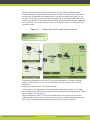
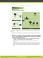
1
SCOPIA XT5000 Series
Installation Guide
Version 3.1
For Solution 7.7, 8.0
© 2000-2012 RADVISION Ltd. All intellectual property rights in this publication are owned by RADVISION Ltd and are
protected by United States copyright laws, other applicable copyright laws and international treaty provisions.
RADVISION Ltd retains all rights not expressly granted.
All product and company names herein may be trademarks of their registered owners.
This publication is RADVISION confidential. No part of this publication may be reproduced in any form whatsoever or
used to make any derivative work without prior written approval by RADVISION Ltd.
No representation of warranties for fitness for any purpose other than what is specifically mentioned in this guide is
made either by RADVISION Ltd or its agents.
RADVISION Ltd reserves the right to revise this publication and make changes without obligation to notify any person
of such revisions or changes. RADVISION Ltd may make improvements or changes in the product(s) and/or the
program(s) described in this documentation at any time.
If there is any software on removable media described in this publication, it is furnished under a license agreement
included with the product as a separate document. If you are unable to locate a copy, please contact RADVISION Ltd
and a copy will be provided to you.
Unless otherwise indicated, RADVISION registered trademarks are registered in the United States and other
territories. All registered trademarks recognized.
For further information contact RADVISION or your local distributor or reseller.
Installation Guide for SCOPIA XT5000 Series Version 3.1, September 24, 2012
http://www.radvision.com
RADVISION | Installation Guide for SCOPIA XT5000 Series Version 3.1
Table of Contents
1
About the SCOPIA XT Series
Technical Specifications................................................................................ 3
2
Planning the Topology of the SCOPIA XT Series Deployment
Using SCOPIA XT Series as Endpoints.................................................................. 8
Using the SCOPIA XT Series Embedded MCU..........................................................9
Hosting Videoconferences with SCOPIA XT Series and SCOPIA XT Desktop..................... 10
Planning NAT and Firewall Traversal with SCOPIA XT Series......................................11
Supporting ISDN Connectivity......................................................................... 14
Implementing External API Control.................................................................. 14
Implementing Port Security for the SCOPIA XT Series............................................. 14
Ports to Open on the SCOPIA XT Series........................................................ 14
Configuring the TCP or UDP Port Range on the SCOPIA XT Series.......................... 18
3
Prerequisites for Setting up the System
Complying with Safety Regulations.................................................................. 20
Planning the Conference Room Setup............................................................... 20
Inspecting the Product.................................................................................22
RADVISION | Installation Guide for SCOPIA XT5000 Series Version 3.1
Table of Contents | i
4
Setting up the SCOPIA XT Series
Mounting of the XT Codec Unit....................................................................... 23
Connecting SCOPIA XT Series......................................................................... 24
Connecting SCOPIA XT Series to Your Network..................................................... 24
Connecting a Computer............................................................................... 24
Selecting the Computer Display Resolution......................................................... 26
Connecting the Audio Equipment.................................................................... 27
Connecting the Microphone Pod................................................................ 27
Connecting an External Microphone System...................................................28
Connecting Analog Stereo Audio Equipment to the Analog Connector.................... 29
Connecting the Video Equipment.................................................................... 30
Connecting the Primary XT Premium Camera.................................................30
Connecting the Optional XT Premium Camera................................................31
Connecting Cameras for Controlling the Optional XT Premium Camera with the XT
Remote Control Unit............................................................................. 33
Using a DVD or Blu-ray Player................................................................... 34
Connecting Analog Video Equipment...........................................................34
Installing the Batteries of the XT Remote Control Unit........................................... 35
5
Initial Configuration
Managing your SCOPIA XT Series from the Web Interface.........................................36
Accessing SCOPIA XT Series Web Interface.................................................... 37
Configuring Remote Management on the SCOPIA XT Series................................. 38
Configuring Remote Upgrade Settings......................................................... 40
Maintaining the SCOPIA XT Series Locally from the Endpoint.................................... 41
Using the XT Remote Control Unit..............................................................43
Pairing an XT Remote Control Unit with a XT Codec Unit................................... 45
Setting the Administrator or User PIN Code for the SCOPIA XT Series Endpoint..........46
Registering and Enabling your SCOPIA XT Series license.......................................... 48
Registering the SCOPIA XT Series to Obtain a License Key.................................. 49
Remotely Enabling the License from the Web Interface.................................... 49
Enabling the License from the SCOPIA XT Series Endpoint.................................. 51
Installing and Enabling Licenses which Extend System Functionality...................... 52
Performing Basic Configuration.......................................................................53
RADVISION | Installation Guide for SCOPIA XT5000 Series Version 3.1
Table of Contents | ii
Setting the System Name and Language....................................................... 54
Adjusting the Image Position.................................................................... 55
Configuring Network Settings................................................................... 57
Configuring Gatekeeper Settings............................................................... 59
Setting Basic System Information.................................................................... 60
Setting Date and Time........................................................................... 61
Setting the Time Zone........................................................................... 62
Setting Regional Information.................................................................... 62
Configuring the Screen Saver to Start Automatically........................................ 63
Configuring Video Connections....................................................................... 65
Configuring the Camera Connection........................................................... 65
Configuring the Computer Connection......................................................... 68
Setting up the Monitor Display Modes.......................................................... 69
Configuring Audio Connections....................................................................... 74
Configuring the Microphone Pod................................................................ 74
Configuring Analog Audio Connections......................................................... 75
Configuring the Echo Canceller................................................................. 78
Configuring Audio Outputs.......................................................................79
Configuring Network Settings......................................................................... 81
Configuring GLAN Use............................................................................ 81
Configuring IP Addresses................................................................... 82
Configuring Network Connectivity........................................................ 84
Enabling NAT and Firewall Traversal with SCOPIA XT Series.......................... 86
Configuring Quality of Service (QoS)......................................................88
Configuring Gatekeeper Use.................................................................... 90
Configuring SIP Server Use.......................................................................93
Configuring SCOPIA XT Series Endpoints to use an LDAP Directory.........................95
Configuring Call Properties.......................................................................... 100
Configuring Call Settings....................................................................... 100
Configuring Audio Compatibility with Older Systems....................................... 103
Configuring Video Compatibility with Older Systems....................................... 104
Securing Calls..........................................................................................105
RADVISION | Installation Guide for SCOPIA XT5000 Series Version 3.1
Table of Contents | iii
1
About the SCOPIA XT Series
The SCOPIA XT Series is a room system endpoint which incorporates state-of-the-art video
technology for high definition (HD) conferencing, including support for dual stream HD video,
high quality data sharing, high quality full band audio and a high capacity embedded MCU to
host videoconferences (selected models).
The SCOPIA XT Series covers a number of different models:
• SCOPIA XT1000 Piccolo
Experience cost-effective true HD 720p videoconferencing at 30 frames per second (fps)
with the SCOPIA XT1000 Piccolo. The wide angle Pan-Tilt-Zoom (PTZ) camera captures the
whole conference room, while 5x zoom offers focus on individuals and details.
The SCOPIA XT1000 Piccolo supports high-resolution PC data sharing at 30fps, enabling
presentations and video clips to be shared at high quality.
The SCOPIA XT1000 Piccolo provides full band audio encoding to ensure clear audio
transmission with crisp quality. The 3-way Microphone Pod provides superb signal-to-noise
ratios.
• SCOPIA XT4000 Series
Experience cost-effective true HD 720p videoconferencing at 60 frames per second (fps)
with the SCOPIA XT4000 Series. Designed for small meeting rooms, this innovative system
combines dual 720p/60fps video, which allows presentations and video clips to be shared
in high quality. The wide angle PTZ camera captures the whole conference room.
To maintain high quality video and audio, the SCOPIA XT4000 Series uses H.264 Scalable
Video Coding Technology (SVC). The SCOPIA XT4000 Series ensures high quality audio even
during poor network conditions, using its 48 kHz sampling rate (full band) audio encoding
capability.
• SCOPIA XT1200
The SCOPIA XT1200 supports two full HD 1080p video streams as standard, delivered at
30fps. The high quality camera features PTZ with 10x optical zoom for powerful viewing
options, and an additional 4x digital zoom. The second video stream can be used with an
additional 1080p camera for visual coverage or with a PC for data sharing, at 1080p
delivered at 30fps. The 3-way Microphone Pod provides superb signal-to-noise ratios. You
can also add a second microphone for unparalleled large room coverage.
• SCOPIA XT Telepresence
RADVISION | Installation Guide for SCOPIA XT5000 Series Version 3.1
About the SCOPIA XT Series | 1
Experience the immersive feeling of telepresence using the SCOPIA XT Telepresence
Platform. To give the feeling of an in-person meeting, the SCOPIA XT Telepresence
incorporates state-of-the-art technology and support for:
–
–
–
Full HD 1080p 30/60 fps video in each of the three cameras
20 kHz full band audio with 48 kHz sampling rate
1080p 30/60fps PC data sharing
• SCOPIA XT5000 Series
The SCOPIA XT5000 Series is the latest product of the SCOPIA XT Series which sets the
standard for an exceptional conferencing experience: HD 1080p with 48 kHz sampling rate
and 60fps for live video and PC data sharing. The SCOPIA XT5000 is designed for an end
user and is very easy to setup and control.
The 3-way Microphone Pod provides superb signal-to-noise ratios. You can also add a
second microphone for unparalleled large room coverage.
For an even better experience, the SCOPIA XT Series is enabled for Multi-Touch control via the
Apple iPad (selected models).
The XT5000 and SCOPIA XT1200 can also host HD continuous presence videoconferences with
their built-in MCU. Depending on your deployment, you can host videoconferences either with
other H.323 and SIP endpoints, or you can extend participants to include both H.323/SIP
endpoints and SCOPIA Desktop Clients:
• SCOPIA XT Series MCU Edition
This features your chosen XT Series model with the ability to host videoconferences with
standard H.323 and SIP endpoints. You can choose a license of up to 4 or 9 participants.
• SCOPIA XT Series SMB Edition
This edition features your chosen XT Series model with the ability to host
videoconferences with both H.323/SIP endpoints and/or SCOPIA Desktop Clients. It
includes the software of the SCOPIA XT Desktop Server which must be deployed in the
DMZ. In this deployment, you can choose a license that allows videoconferences with up
to either 4 or 9 participants.
Note
If your license allows 9 participants, you can include up to 8 remote endpoints.
If any participants in the videoconference connect from SCOPIA Desktop Clients (PC
or mobile), you can include up to 7 remote endpoints, since one port is reserved for
connecting to the SCOPIA Desktop Server.
For more information on the SMB Solution deployment, see the Solution Guide for SCOPIA
Solution.
RADVISION | Installation Guide for SCOPIA XT5000 Series Version 3.1
About the SCOPIA XT Series | 2
Technical Specifications
This section details the system specifications of the SCOPIA XT Series you purchased. Refer to
this data when preparing system setup and afterwards as a means of verifying that the
environment still complies with these requirements:
• For physical details of the system, such as the power requirements and weight of each
component, see Table 1-1 on page 3.
• For specific video, audio, and control features of the system, such as supported codecs
and web browsers, see Table 1-2 on page 4.
• For network information of the system, such as network interface cards, see Table 1-3 on
page 5.
• For an overview of features and to compare between different XT Series models, see
Table 1-4 on page 6.
Table 1-1 on page 3 refers to the physical details of the device.
Table 1-1
Physical device specifications
SCOPIA XT5000 Series
System power requirements
100-240 VAC, 50/60 Hz, 1.8 A Max.
Maximum power consumption
60W (205 BTU/h)
Operating temperature
0°C to 40°C (32°F to 104°F)
Relative humidity
5% to 90% non-condensing
Storage temperature
Physical dimensions and Net
Weight
Camera
Physical dimensions and Net
weight
Microphone Pod
Physical dimensions and Net
weight
Microphone Pod capabilities
SCOPIA XT4000 Series
-40°C to 70°C (-40°F to 158°F), ambient
Height: 4cm (1.6"), Width: 29cm (11.4"); Depth 16.5cm (6.5")
Weight: 2.4 kg (5.3 lb)
Height: 15,2cm (6.0"), Width: 25cm (9.8"); Depth 13.5cm
(5.3")
Weight: 1.6 kg (3.5 lb)
Diameter: 14cm (5.5"),
Weight: 0.3 kg (0.7 lb)
Diameter: 12cm (4.7"),
Weight: 0.4 kg (0.9 lb)
360º range
180º range
Frequency response: 50 –
22,000 Hz
Frequency response: 50 –
20,000 Hz
Up to 2 cascaded pods
Table 1-2 on page 4 lists the protocols and software requirements.
RADVISION | Installation Guide for SCOPIA XT5000 Series Version 3.1
About the SCOPIA XT Series | 3
Table 1-2
Video, audio and control capabilities
SCOPIA XT5000 Series
Signaling protocols
Video codecs
Dual video
HDMI input formats
SCOPIA XT4000 Series
H.323, SIP, ISDN (in conjunction with SCOPIA Gateway)
H.263, H.263+, H.263++,H.264, H.264 SVC, H.264 High Profile,
H.264 High Profile SVC
H.239 (H.323); BFCP (SIP)
1920 x 1080 @ 25, 30, 50, 60fps
1280 x 720 @ 25, 30, 50, 60fps
720 x 576 @ 50fps
720 x 480 @ 60fps
640 x 480 @ 60fps
Live video resolution
1920 X 1080 @ 25, 30, 50,
60fps: HD1080p25, 30, 50, 60
1280 x 720 @ 25, 30, 50,
60fps: HD720p25, 30, 50, 60
1280 x 720 @ 25, 30, 50,
60fps: HD720p25, 30, 50, 60
1024 x 576 @ 25, 30fps: w576p
704 x 576 @ 25, 30fps: 4CIF
576 x 336 @ 25, 30fps
704 x 480 @ 25, 30fps: 4SIF
512 x 288 @ 25, 30fps: wCIF
576 x 336 @ 25, 30fps
400 x 224 @ 25, 30fps
512 x 288 @ 25, 30fps: wCIF
352 x 288 @ 25, 30fps: CIF
400 x 224 @ 25, 30fps
352 x 240 @ 25, 30fps: SIF
768 x 448 @ 25, 30fps: w448p
1024 x 576 @ 25, 30fps: w576p 704 x 576 @ 25, 30fps: 4CIF
768 x 448 @ 25, 30fps: w448p 704 x 480 @ 25, 30fps: 4SIF
352 x 288 @ 25, 30fps: CIF
352 x 240 @ 25, 30fps: SIF
Presentation video resolution
1920 x 1080 @ 25, 30, 50,
60fps
1280 x 720 @ 25, 30, 50, 60fps
1280 x 768 @ 60fps: WXGA
1440 x 900 @ 60fps: WSXGA
1024 x 768 @ 60fps: XGA
1280 x 1024 @ 60fps: SXGA
800 x 600 @ 60fps: SVGA
1280 x 720 @ 25, 30, 50, 60fps 640 x 480 @ 60fps: VGA
1280 x 768 @ 60fps: WXGA
1024 x 768 @ 60fps: XGA
800 x 600 @ 60fps: SVGA
640 x 480 @ 60fps: VGA
HDMI output formats
1920 x 1080 @ 25, 30, 50,
60fps
1280 x 720 @ 50, 60fps
1280 x 720 @ 50, 60fps
RADVISION | Installation Guide for SCOPIA XT5000 Series Version 3.1
About the SCOPIA XT Series | 4
SCOPIA XT5000 Series
Video bandwidth
SCOPIA XT4000 Series
Up to 12Mbps for a multipoint Up to 4Mbps for 720p
call
Up to 6Mbps for 1080p in a
point-to-point call
Camera resolution
1080p 60fps
Audio codecs
G.711, G.728, G.729A, G.722, G.711, G.728, G.722, G.722.1,
G.722.1, G.722.1 Annex C,
G.722.1 Annex C, G.719
G.719, AAC-LD
Web browser support
720p 60fps
Internet Explorer version 7 or later
Google Chrome (latest version)
Mozilla Firefox version 3.6 or later
Apple Safari version 5 or later
Opera version 11 or later
Table 1-3 on page 5 lists the XT Series's network interface and firewall traversal
information.
Table 1-3
Network and security capabilities
Network Interfaces
SCOPIA XT5000 Series
SCOPIA XT4000 Series
2 x 10/100/1000 Base-T fullduplex (RJ-45)
2 x 10/100/1000 Base-T fullduplex (RJ-45).
(2nd GLAN is optional)
Firewall Traversal
Auto NAT discovery HTTP and STUN
H.460.18, H.460.19
Table 1-4 on page 6 summarizes the differences between each of the models in the SCOPIA
XT Series.
RADVISION | Installation Guide for SCOPIA XT5000 Series Version 3.1
About the SCOPIA XT Series | 5
Table 1-4
Differences in features for models in the SCOPIA XT Series
Feature
SCOPIA
XT1000
Piccolo
SCOPIA XT1200 SCOPIA XT
Telepresence
SCOPIA
SCOPIA
XT4000 Series XT5000
Series
Maximum HD
resolution
720p
1080p
3 x 1080p
720p
Frames Per
Second (fps)
30fps
30fps, 720p at
60fps (outgoing
only for XT1000
is 720p 30fps)
Depends on the 60fps
XT Codec Unit;
see SCOPIA
XT1200 or
SCOPIA XT5000
Series
60fps, both at
720p and
1080p
Hosting
No
videoconferenc
es (embedded
MCU)
Optional
No
No
Optional
Optical zoom
5x
10x
10x
5x (10x
optional)
10x
Total zoom
(optical x
digital)
5x
10x (40x
optional)
N/A
40x (optional) 40x
Dual video
720p at
30fps
1080p at 30fps
Depends on the 720p at 60fps
XT Codec Unit;
see SCOPIA
XT1200 or
SCOPIA XT5000
Series (x 3 for
transmission)
1080p at 60
fps
Scalable video No
coding
No
Depends on the Yes
XT Codec Unit;
see SCOPIA
XT1200 or
SCOPIA XT5000
Series
Yes
High Profile
H.264
No
No
Depends on the Yes
XT Codec Unit;
see SCOPIA
XT1200 or
SCOPIA XT5000
Series
Yes
Type of
Microphone
Pod
3-way
3-way
3-way
3-way
RADVISION | Installation Guide for SCOPIA XT5000 Series Version 3.1
1-way
1080p
About the SCOPIA XT Series | 6
Feature
SCOPIA
XT1000
Piccolo
SCOPIA XT1200 SCOPIA XT
Telepresence
Additional
Ethernet
connection
Optional
(10/100)
Optional
(10/100)
Depends on the Optional
Yes
XT Codec Unit; (10/100/1000) (10/100/1000)
see SCOPIA
XT1200 or
SCOPIA XT5000
Series
SCOPIA Control Optional
Optional
Yes
RADVISION | Installation Guide for SCOPIA XT5000 Series Version 3.1
SCOPIA
SCOPIA
XT4000 Series XT5000
Series
Optional
Yes
About the SCOPIA XT Series | 7
2
Planning the Topology of the SCOPIA XT Series
Deployment
There are a number of ways that the SCOPIA XT Series can be deployed in a network,
depending on whether you use it as a room system endpoint or a conference hosting system,
and the type of the endpoints connecting to the unit.
• Using SCOPIA XT Series as Endpoints ...................................................... page 8
• Using the SCOPIA XT Series Embedded MCU .............................................. page 9
• Hosting Videoconferences with SCOPIA XT Series and SCOPIA XT Desktop .......... page 10
• Planning NAT and Firewall Traversal with SCOPIA XT Series .......................... page 11
• Supporting ISDN Connectivity ............................................................. page 14
• Implementing External API Control ...................................................... page 14
• Implementing Port Security for the SCOPIA XT Series ................................. page 14
Using SCOPIA XT Series as Endpoints
Figure 2-1 on page 9 illustrates a topology in which the SCOPIA XT Series act as endpoints:
• The MCU (for example, SCOPIA Elite MCU) performs media processing for endpoints
regardless of their location and can handle multiple conferences simultaneously (includes
all connected SCOPIA XT Series, SCOPIA VC240 and compatible third-party endpoints).
SCOPIA Elite MCU incorporates multi-party 1080p, 720p and H.264 Scalable Video Coding
(SVC).
• SCOPIA VC240 integrates advanced video conferencing into a Samsung high resolution 24inch multimedia LCD monitor.
RADVISION | Installation Guide for SCOPIA XT5000 Series Version 3.1
Planning the Topology of the SCOPIA XT Series Deployment | 8
Figure 2-1
SCOPIA XT Series as Endpoints
Using the SCOPIA XT Series Embedded MCU
The SCOPIA XT Series MCU Edition includes an embedded MCU and is available as a license
option for the XT5000 and SCOPIA XT1200 models only.
Activate the MCU capability by registering the XT Codec Unit, as described in “Registering the
SCOPIA XT Series to Obtain a License Key”.
The SCOPIA XT Series MCU Edition can deploy two levels of MCUs:
• MCU4 - Host videoconferences with up to 4 participants (1 Local and 3 Remote).
• MCU9 - Host videoconferences with up to 9 Participants (1 Local and 8 Remote).
The embedded MCU can host standard definition (SD) and high definition (HD) endpoints
simultaneously (see Table 2-1 on page 9 for details). The presence of SD endpoints does
not affect the quality received by HD endpoints. SD endpoints will receive SD video streams
and HD endpoints will receive HD video streams. In the same way 4:3 and 16:9 video formats
are included in the best possible way into the continuous presence (CP) mosaic.
Table 2-1
Video capabilities for participants hosted by SCOPIA XT Series
MCU Edition
Maximum Resolution
XT5000
SCOPIA XT1200
Displayed and transmitted
resolution (max)
1080p
720p
Resolution of single
participant's video in layout
(max)
448p
448p
RADVISION | Installation Guide for SCOPIA XT5000 Series Version 3.1
Planning the Topology of the SCOPIA XT Series Deployment | 9
Note
For MCU9, the capabilities depend on the selected CP layout.
For the best experience when using the SCOPIA XT Series MCU Edition, we recommend:
• Enabling the High Bandwidth Option (12Mbps), available as a separate license (for details,
see Installation Guide for the SCOPIA XT Series). Otherwise, the MCU sends out a lower
resolution at the standard 6Mbps total bandwidth.
• If the SCOPIA XT Series is used only as an MCU for hosting videoconferences, block the
audio and video input from this SCOPIA XT Series during the meeting. For details, see the
User Guide for SCOPIA XT Series.
Hosting Videoconferences with SCOPIA XT Series and SCOPIA XT Desktop
You can enable this functionality by registering your XT Series using the MCU/SCOPIA XT
Desktop product key. SCOPIA XT Desktop is supported for selected models only, and requires
SCOPIA XT Desktop version 7.7.100.221 or later.
SCOPIA XT Desktop expands the possibilities of hosting videoconferences on the XT Series by
enabling participants to join a videoconference with just a PC, web browser or a mobile
device.
The SCOPIA XT Desktop solution combines HD room system capabilities, embedded multi-party
conferencing, desktop conferencing and firewall traversal. The SCOPIA XT Desktop option is
delivered on a CD for installation on a separate server.
The solution enables remote users to easily connect to a meeting, relying only on the XT
Series and its embedded MCU with no extra hardware to acquire, deploy and configure. A
single SCOPIA Desktop Server is deployed with a single XT Series unit, utilizing the endpoint’s
embedded MCU.
For example, when a meeting is held in a conference room with the XT Series hosting the call,
and a remote user is connected with an endpoint, other remote users can use their web
browsers to point it to the SCOPIA XT Desktop to connect to the meeting.
Two levels of SMBs are available:
• Full SMB4 - Basic MCU level with up to 4 participants: 1 local and 3 remote mixed
endpoints and PC clients.
• Full SMB9 - Advanced MCU level with up to 9 participants:
– 1 local and 8 remote endpoints
Or
–
1 local and 7 mixed endpoints and PC clients
RADVISION | Installation Guide for SCOPIA XT5000 Series Version 3.1
Planning the Topology of the SCOPIA XT Series Deployment | 10
Planning NAT and Firewall Traversal with SCOPIA XT Series
SCOPIA XT Series fully supports NAT and firewall traversal, enabling you to place the unit
behind a NAT router or firewall and connect with other endpoints seamlessly. This section
describes four approaches to NAT and firewall traversal with XT Series:
• Using a RADVISION HTTP server or a STUN public server for NAT and firewall traversal
When the XT Series hosts a videoconference with endpoints outside the enterprise (Figure
2-2 on page 11), it first queries the HTTP or STUN server to discover its public IP
address, then sends it to any external endpoints wishing to join the conference. The
external endpoints then answer the call using the IP address provided. Configure the XT
Codec Unit for HTTP or STUN autodiscovery.
Figure 2-2
Using an HTTP/STUN Server for NAT and Firewall Traversal
This approach works well in simple NAT and firewall traversal deployments, typically used
by home offices and Small Medium Businesses (SMBs).
• Using a NAT/firewall traversal server supporting H.460
The endpoints in the private network communicate with the endpoints located in the
public network via an H.460 NAT/firewall traversal server, like the SCOPIA PathFinder (see
Figure 2-3 on page 12). Endpoints in the public network can join a conference hosted in
the private network via the traversal server if there is an open connection through the
firewall. Verify the duration of the firewall pinhole and configure that time in the XT
Codec Unit.
RADVISION | Installation Guide for SCOPIA XT5000 Series Version 3.1
Planning the Topology of the SCOPIA XT Series Deployment | 11
Having a dedicated NAT/firewall traversal server like the SCOPIA PathFinder offers
external endpoints a static address when joining conferences hosted in your organization.
You can dial [email protected] to access from outside the firewall, or you
can dial 1234 directly if you are a H.460 client logged in to the SCOPIA PathFinder Server.
H.460 is an extension of the H.323 protocol used for NAT and firewall traversal, employing
ITU-T standards. The traversal server can be a a SCOPIA PathFinder or a third-party ITU-T
compliant server.
Figure 2-3
Using a NAT and Firewall Traversal Server
Configure the traversal server as the XT Codec Unit gatekeeper and enable the H.460
option. Configure the XT Codec Unit to the IP address of the traversal server SCOPIA
PathFinder.
• Using the XT Series for NAT and firewall traversal
In cases where your organization has no sophisticated firewall protection, the XT Series
can straddle the two network zones using the two network ports provided on the XT Codec
Unit (see Figure 2-4 on page 13).
Use the GLAN ports of the XT Codec Unit simultaneously and connect one port to the
public network and the other to your private network. All communication passes through
the XT Series which acts as the virtual conference room for all the endpoints.
RADVISION | Installation Guide for SCOPIA XT5000 Series Version 3.1
Planning the Topology of the SCOPIA XT Series Deployment | 12
Figure 2-4
Using XT Series for NAT and Firewall Traversal
There are two possible setups in the GLAN1 and GLAN2 configuration (see Figure 2-4 on
page 13):
1. When there is no gatekeeper, XT Series communicates simultaneously with the public
and private network endpoints using IP addresses. This configuration is suitable for
SMBs.
2. When there is a gatekeeper, it is configured to manage the private network endpoints.
SCOPIA XT Series is registered with the gatekeeper and communicates with endpoints
in the private and in the public network:
–
SCOPIA XT Series communicates with the private network endpoints using IP
addresses or aliases, under the control of the gatekeeper.
–
SCOPIA XT Series communicates with the public network endpoints using IP
addresses.
–
SCOPIA XT Series communicates at the same time both with the public and private
endpoints if the MCU option is activated. In this scenario SCOPIA XT Series uses
either aliases or IP addresses depending on whether it deploys the gatekeeper or
not.
RADVISION | Installation Guide for SCOPIA XT5000 Series Version 3.1
Planning the Topology of the SCOPIA XT Series Deployment | 13
Supporting ISDN Connectivity
The SCOPIA XT Series supports ISDN connectivity, allowing calls from endpoints to be routed to
the relevant conference using the SCOPIA BRI (Basic Rate Interface) and PRI (Primary Rate
Interface) gateways.
RADVISION has implemented a special pairing mechanism between the gateway and the
endpoint so that ISDN dialing is very simple. After pairing the systems, the participants place
ISDN calls by dialing the remote party ISDN number. The system automatically and
transparently takes care of setting the bit rate and call routing through the ISDN gateway.
A single gateway can serve multiple endpoints. For example, an organization needs to enable
5 endpoints with ISDN connectivity. Assuming the requested ISDN connectivity speed is
256bps, use only one ISDN PRI gateway as it can support 5 concurrent calls of 256bps each.
With the gateway approach less communication lines are needed. As all gateways do not
connect at the same time and not all calls are ISDN, many more endpoints can share the same
ISDN connection and gateway.
Implementing External API Control
You can control the XT Codec Unit using the SCOPIA XT Series API (requires integration with
AMX, Creston, or Extron control devices). Contact RADVISION customer support to receive the
Reference Guide for SCOPIA XT Series API, which includes the list of commands over the
Ethernet interface.
Implementing Port Security for the SCOPIA XT Series
The SCOPIA XT Series provides video technology for room conferencing, including support for
dual stream 1080p video, high quality data sharing, high quality full band audio and a high
capacity embedded MCU.
This section details the ports used for the SCOPIA XT Series and the relevant configuration
procedures:
• Ports to Open on the SCOPIA XT Series ..................................................
• Configuring the TCP or UDP Port Range on the SCOPIA XT Series ....................
page 14
page 18
Ports to Open on the SCOPIA XT Series
The SCOPIA XT Series is typically located in the enterprise network and is connected to the
DMZ. When opening ports to and from the SCOPIA XT Series, use the following as a reference:
• If you are opening ports that are both to and from the SCOPIA XT Series, see Table 2-2 on
page 16.
• If you are opening outbound ports from the SCOPIA XT Series, see Table 2-3 on page 18.
RADVISION | Installation Guide for SCOPIA XT5000 Series Version 3.1
Planning the Topology of the SCOPIA XT Series Deployment | 14
Note
The specific firewalls you need to open ports on depends on where your SCOPIA XT Series and
other SCOPIA Solution products are deployed.
RADVISION | Installation Guide for SCOPIA XT5000 Series Version 3.1
Planning the Topology of the SCOPIA XT Series Deployment | 15
Table 2-2
Bidirectional Ports to Open on the SCOPIA XT Series
Port Range
Protocol
Destination
Functionality
Result of Blocking
Port
Required
69
TFTP (UDP)
TFTP client or
server
Enables sending and
receiving files via TFTP
Cannot send or
receive files via
TFTP
Optional
80
HTTP (TCP)
Web server
Enables you to remotely
perform management
tasks via the web user
interface, enables NAT
auto-discovery via HTTP
In: Cannot access
the web server
Recommended
Out: Cannot access
the web server and
NAT auto-discovery
via HTTP does not
function
123
SNTP (UDP)
SNTP client
Gets the Internet UTC
time
Cannot get the
Internet UTC time
161
SNMP (UDP)
SCOPIA
Management or
any other SNMP
manager station
Enables you to configure
the endpoint and check
the endpoint status
Cannot configure or Mandatory if using
check the status of SNMP manager
the endpoint via
station
SNMP
1719
H.225.0/
RAS (UDP)
Any H.323 video
network device
Enables H.323 call
H.323 endpoints
Recommended
signaling to a gatekeeper; cannot use
H.323 endpoints can use
gatekeeper services
gatekeeper services.
1720
H.225.0/
Any H.323 video
Q.931 (TCP) network device
Enables H.323 call
signaling (Q.931)
Cannot connect
H.323 calls
Mandatory
3230-3248
H.225.0/Q.9 Any H.323 video
31/ H.245/ network device
SIP (TCP)
Enables H.323 call control Cannot connect
signaling (Q.931), media
SIP/H.323 calls
control signaling (H.245),
SIP (TCP) call signaling,
and BFCP signaling.
Ephemeral TCP ports are
used to connect
simultaneous H.323 and
SIP calls.
Mandatory
RTP and
RTCP (UDP)
Enables H.323 and SIP
media (audio, video,
H.224/data RTP) and
media control (RTCP).
Ephemeral UDP ports are
used to connect
simultaneous H.323 and
SIP media calls.
3230-3305
Any H.323 video
network device
RADVISION | Installation Guide for SCOPIA XT5000 Series Version 3.1
Recommended
To configure, see
“Configuring the
TCP or UDP Port
Range on the
SCOPIA XT Series”
on page 18
No media
Mandatory
exchanged in H.323 To configure, see
or SIP calls
“Configuring the
TCP or UDP Port
Range on the
SCOPIA XT Series”
on page 18
Planning the Topology of the SCOPIA XT Series Deployment | 16
Port Range
Protocol
Destination
3338
XML
Commands
(TCP)
SCOPIA Control,
Enables communication
SCOPIA XT Desktop with SCOPIA Control and
Server
SCOPIA XT Desktop Server
by sending commands and
receiving responses
Cannot
Optional
communicate with
SCOPIA Control
application or and
SCOPIA XT Desktop
Server
3478, 3479
STUN (UDP)
STUN Server
Enables endpoints outside
of the enterprise firewall
to determine their public
IP address and
automatically discover the
presence of a firewall or
NAT
Cannot
automatically
discover the
presence of a
firewall or NAT
(only manual
configuration
available)
5060
SIP (TCP)
Any SIP-enabled
video network
device
Enables SIP call signaling
Cannot connect SIP Mandatory
calls over TCP
5060
SIP (UDP)
Any SIP-enabled
video network
device
Enables SIP call signaling
Cannot connect SIP Mandatory
calls over UDP
5070
BFCP (TCP)
Any SIP-enabled
video network
device
Enables SIP video content
(presentation) signaling
No SIP video
content available
Mandatory
55003
AT
Commands
(TCP)
SCOPIA
Management
Enables you to remotely
manage the SCOPIA
XT1000 via API
Cannot send/
receive commands
Optional
55099
Software
Upgrade
(TCP)
SCOPIA
Enables software upgrade
Management/
SCOPIA XT Series
Software Upgrade
application
Cannot upgrade
software
Recommended
60123
Telnet (TCP) Telnet server
No Telnet access
Optional
RADVISION | Installation Guide for SCOPIA XT5000 Series Version 3.1
Functionality
Enables remote
management via Telnet
Result of Blocking
Port
Required
Optional
Planning the Topology of the SCOPIA XT Series Deployment | 17
Table 2-3
Outbound Ports to Open from the SCOPIA XT Series
Port Range
Protocol
Destination
Functionality
162
SNMP (UDP)
SCOPIA
Management or
any other SNMP
manager station
Enables sending SNMP Endpoints cannot send
trap events
SNMP events
1718
H.225.0/ RAS
(UDP)
Multicast IP
Enables H.323
H.323 endpoints can
address 224.0.1.41 endpoints to
only register with a
(all gatekeepers) automatically identify predefined gatekeeper
the gatekeeper to
register with
Recommended
3339, 3340
XML HINTS
(TCP)
SCOPIA Control,
Enables receiving
SCOPIA XT Desktop system status alerts
Server
Optional
Result of Blocking Port Required
Cannot send system
status alerts; SCOPIA
Control and SCOPIA XT
Desktop Server cannot
function.
Optional
Configuring the TCP or UDP Port Range on the SCOPIA XT Series
You can configure the TCP or UDP port range by setting the base port, which is the lower end
of the port range (if, for example, port 3230 is busy).
The SCOPIA XT Series uses dynamic TCP ports 3230-3248 for the following:
• H.225.0: An H.323 protocol that specifies the messages and procedures used by
gatekeepers to set up calls.
• Q.931:A telephony protocol used for establishing and terminating the connection in H.323
calls.
• H.245: A Control Protocol used for multimedia communication; enables transferring
information about the device capabilities, as well as opening/closing the logical channels
that carry media streams.
• SIP: A signaling protocol used for creating, modifying, or terminating multimedia
connections between two or more participants.
The SCOPIA XT Series uses dynamic UDP ports 3230-3248 for enabling real-time H.323 and SIP
media, including audio, video, and H.224/data (RTP), and media control (RTCP).
Procedure
Step 1
Access the port settings as follows:
• From the web interface, select Administrator Settings > Networks > Preferences >
Dynamic Ports.
• From the endpoint interface, select Configure > Advanced > Networks > Preferences >
Dynamic Ports.
RADVISION | Installation Guide for SCOPIA XT5000 Series Version 3.1
Planning the Topology of the SCOPIA XT Series Deployment | 18
Figure 2-5
Step 2
Configuring the TCP or UDP port range from the web interface
Define how the XT Codec Unit assigns ports by selecting one of the following from Auto
detect:
• No: The XT Codec Unit uses the range of dynamic ports indicated and allows you to
define the base port (default and recommended setting).
• Yes: The XT Codec Unit assigns ports randomly, and you cannot define the base port.
Step 3
If you selected No in the Auto detect list, you can modify the TCP or UDP base port in the
Ports field.
Note
Step 4
You can configure the base port to any value between 1024-65535. The number of
ports is calculated automatically by the system, depending on whether you have an
MCU license and its type.
In the web interface, select Save.
Note
In the endpoint, your changes are saved automatically.
RADVISION | Installation Guide for SCOPIA XT5000 Series Version 3.1
Planning the Topology of the SCOPIA XT Series Deployment | 19
3
Prerequisites for Setting up the System
Before beginning the installation of the system, you must read the safety regulations for a
safe use of the system, verify the conference room setup, and check that the product
corresponds to your order. The setup prerequisites are described in these sections:
• Complying with Safety Regulations ......................................................
• Planning the Conference Room Setup ...................................................
• Inspecting the Product .....................................................................
page 20
page 20
page 22
Complying with Safety Regulations
For detailed safety information consult the SCOPIA XT Series Safety Instructions leaflet
enclosed in the delivery package.
Planning the Conference Room Setup
Set up the conference room to enjoy virtual meeting. RADVISION provides useful information
on conference room setup in http://blog.radvision.com/videooverenterprise/2010/05/11/askthe-expert-designing-your-conference-room/
SCOPIA XT Series can receive the Infra-Red (IR) command of the XT Remote Control Unit via:
• The XT Codec Unit IR receiver
• The IR receiver of the XT Premium Camera or XT Standard II Camera. In this case the XT
Remote Control Unit sends the command to the XT Codec Unit using the VISCA connection.
The position of the XT Codec Unit in the conference room is not important for receiving
the signal from the XT Remote Control Unit. But it is important to connect the main
camera correctly to the XT Codec Unit via the VISCA Cross cable.
Place the XT Codec Unit anywhere within 5 meter reach of the camera cables. Leave enough
space for air circulation and for connecting cables easily.
RADVISION | Installation Guide for SCOPIA XT5000 Series Version 3.1
Prerequisites for Setting up the System | 20
Place the camera(s) in a position to ensure eye contact between local and remote
participants. Recommended position is either directly below or directly above the monitors, in
central position, at a distance which enables capture of the entire table.
Caution
Do not place the camera on top of the XT Codec Unit. It can cause the system to overheat.
Place the Microphone Pod at the center of the table. To help with echo cancellation, we
recommend to position the Microphone Pod as far as possible from loudspeakers and other
noise sources (for example, computer fans).
Figure 3-1
Suggested Room Setup
Avoid white walls as they can introduce an effect-like backlight: a white wall increases the
illumination behind the person. Avoid glass walls, as well as patterns and textures on the walls
as they may cause disturbances to visual effects. We recommend to have plain walls of
neutral color. Also, in order to avoid reverberations, we recommend to use heavy curtains of
neutral color and carpets.
The conference room should be air-conditioned and kept at a cool temperature to avoid the
XT Codec Unit switching on its fan.
The conference room should be well and uniformly lit, avoiding a mixture of natural and
artificial light. Light should come from the top of the conference table, the front and the rear
(for depth of field). If only ceiling light is available, it should contribute to maintain a
pleasant environment and generate as less heat as possible.
The IR sensors of the XT Codec Unit and the camera might not receive the infrared rays under
sunlight or near inverter fluorescent lamps.
RADVISION | Installation Guide for SCOPIA XT5000 Series Version 3.1
Prerequisites for Setting up the System | 21
Inspecting the Product
Inspect the contents of the package for shipping damages.
For a list of package contents see the invoice shipped with your order.
Report any damage or missing items to your distributor or reseller.
Keep the package and its contents for inspection resulting from loss or damage claim.
RADVISION | Installation Guide for SCOPIA XT5000 Series Version 3.1
Prerequisites for Setting up the System | 22
4
Setting up the SCOPIA XT Series
After reading the section “Prerequisites for Setting up the System” on page 20, you can install
the SCOPIA XT Series. These sections describe how to install the XT Codec Unit and connect it
to its peripherals:
• Mounting of the XT Codec Unit ...........................................................
• Connecting SCOPIA XT Series .............................................................
• Connecting SCOPIA XT Series to Your Network .........................................
• Connecting a Computer ....................................................................
• Selecting the Computer Display Resolution .............................................
• Connecting the Audio Equipment .........................................................
• Connecting the Video Equipment .........................................................
• Installing the Batteries of the XT Remote Control Unit ................................
page 23
page 24
page 24
page 24
page 26
page 27
page 30
page 35
Mounting of the XT Codec Unit
Follow the guidelines in this section to correctly place the XT Codec Unit.
Procedure
Place the XT Codec Unit following these guidelines:
• Place the XT Codec Unit on a horizontal surface which stands firmly on its base.
• The surface must be dry and free of dust, oil and other residues.
• Leave enough space for air circulation and for connecting cables easily.
• Place the XT Codec Unit anywhere within 5 meter reach of the camera cables.
Caution
Do not place the camera on top of the XT Codec Unit. It can cause the system
to overheat.
RADVISION | Installation Guide for SCOPIA XT5000 Series Version 3.1
Setting up the SCOPIA XT Series | 23
Connecting SCOPIA XT Series
For operational information about connecting SCOPIA XT5000 Series, refer to the Quick Setup
Guide for SCOPIA XT5000 Series.
Connecting SCOPIA XT Series to Your Network
Your SCOPIA XT Series has two GLAN 10/100/1000 ports for connecting to the network.
You can use both ports for connecting to the private and public network, however we
recommend that you always connect the private network to the second GLAN port, whether
one router interfaces with the SCOPIA XT Series or multiple routers interface with the SCOPIA
XT Series (Figure 4-1 on page 24).
Figure 4-1
Connecting the XT Codec Unit to a private and a public network
Connecting a Computer
Use a computer to share a presentation or other PC content during a call. This procedure
describes how to connect computers that are equipped with a DVI-out or VGA-out connector.
The XT Codec Unit supports many DVI input resolutions, listed in Table 4-1 on page 25.
RADVISION | Installation Guide for SCOPIA XT5000 Series Version 3.1
Setting up the SCOPIA XT Series | 24
Table 4-1
DVI input formats supported by XT Codec Unit
Name
Resolution
1080p
1920x1080
SXGA
1280x1024
HD+ (900p)
1600x900
WSGA
1440x900
UVGA
1280x960
WXGA
1280x768
720p
1280x720
XGA
1024x768
SVGA
800x600
VGA
640x480
Procedure
Step 1
Connect your computer to the XT Codec Unit:
• For computers and laptops with a DVI out connector, connect the DVI cable to the DVI-I
socket of the XT Codec Unit and connect the other end of the cable to the computer.
Figure 4-2
Connecting a computer to SCOPIA XT Series
• For computers with a VGA output connector, use the included DVI to VGA adapter.
a. Connect the DVI-VGA adapter to the DVI-IN socket of the XT Codec Unit.
b. Connect a VGA cable to the adapter. This cable is not supplied with the system.
c. Connect the VGA cable to the PC/Laptop VGA out socket.
Step 2
Connect the computer audio to the XT Codec Unit.
RADVISION | Installation Guide for SCOPIA XT5000 Series Version 3.1
Setting up the SCOPIA XT Series | 25
Since audio input is not included in the DVI-I port to XT Codec Unit connection, you need to
make a separate audio connection from the computer’s audio output port into the audio
input port of the XT Codec Unit.
Note
Step 3
The audio input port supports both analog and digital optical audio.
Continue with setting the display resolution, as described in “Selecting the Computer Display
Resolution” on page 26.
Selecting the Computer Display Resolution
For optimal display quality, and to prevent the screen from flickering during the
videoconference, set the computer display to one of the supported picture resolutions and
refresh frequencies. This procedure assumes computers running Microsoft Windows.
Procedure
Step 1
Step 2
From the Windows Control Panel, navigate to the screen resolution settings.
Step 3
Step 4
Select Apply.
Select the desired screen resolution. See Table 4-2 on page 26 for the list of resolutions
supported by the XT Codec Unit.
Select the refresh frequency rate from the Screen refresh rate field. See Table 4-2 on page
26 for the supported resolution and refresh rates.
Table 4-2
Step 5
Resolution and Refresh Frequencies
Name
Resolution
Digital Refresh Frequency (Hz)
Analog Refresh Frequency (Hz)
1080p
1920x1080
60
60
SXGA
1280x1024
60,75
60, 75
HD+
(900p)
1600x900
60
N/A
WSGA
1440x900
60
60
UVGA
1280x960
60, 85
60, 85
WXGA
1280x768
60
N/A
720p
1280x720
60
60
XGA
1024x768
60, 70, 75
60, 70, 75
SVGA
800x600
60, 72, 75
60, 72, 75
VGA
640x480
72, 75
72, 75
Select Apply.
RADVISION | Installation Guide for SCOPIA XT5000 Series Version 3.1
Setting up the SCOPIA XT Series | 26
Connecting the Audio Equipment
These sections describe how to connect the audio peripherals to the XT Codec Unit.
• Connecting the Microphone Pod ..........................................................
• Connecting an External Microphone System ............................................
• Connecting Analog Stereo Audio Equipment to the Analog Connector ..............
page 27
page 28
page 29
Connecting the Microphone Pod
The 3-way Microphone Pod performance varies with room characteristics, background noise
levels, and loudness and position of speakers.
When used in typical settings, the Microphone Pod can cover a radius of 2 meters (about 6.5
feet).
The second Microphone Pod is available for selected models only. You cannot use more than
two Microphone Pods for one system.
In the current version release, the XT Codec Unit does not encode/decode stereo signals.
For optimal results:
• Place the Microphone Pod at the center of the table.
• In a larger conference room, connect 2 Microphone Pods. Distribute them evenly on the
table.
• To help with echo cancellation, we recommend that you position the Microphone Pod as
far as possible from loudspeakers and other noise sources (for example, computer fans).
Figure 4-3
RADVISION | Installation Guide for SCOPIA XT5000 Series Version 3.1
Microphone Setup
Setting up the SCOPIA XT Series | 27
Procedure
Step 1
Connect the Microphone Pod output
to the rear panel of the XT Codec Unit.
Figure 4-4
Figure 4-5
Step 2
Microphone Pod
Connecting the Microphone Pods to the XT Codec Unit of SCOPIA
XT5000 Series
(Optional) Connect the second Microphone Pod output
.
to the first Microphone Pod input
Connecting an External Microphone System
When the two-pod configuration is not sufficient for covering the room, use an external
microphone system.
You need to acquire audio mixers from third-parties (for example, Clear One). An audio mixer
can connect multiple microphones, mix them, cancel the echo and generate a single audio
stream that feeds into the audio inputs of your SCOPIA XT Series XT Codec Unit.
RADVISION | Installation Guide for SCOPIA XT5000 Series Version 3.1
Setting up the SCOPIA XT Series | 28
Make sure the microphone mixer provides these connectors: an analog audio I/O (mini jack
3.5”) connector and a digital optical connector with a mini-TOSlink adapter
SCOPIA XT Series supports echo cancellation on the external audio interface.
You must enable the echo canceller when working with an external microphone system that
does not contain echo cancellation. See “Configuring the Echo Canceller” on page 78.
Disable echo cancellation when working with an external mixer that handles echo cancellation
externally.
Connecting Analog Stereo Audio Equipment to the Analog Connector
You can connect analog audio equipment (for example, an external amplifier) to the stereo
analog connector of the XT Codec Unit. This procedure describes how to connect an external
amplifier.
You must enable the echo canceller when working with an external microphone system that
does not contain echo cancellation. See “Configuring the Echo Canceller” on page 78.
Note
The XT Codec Unit’s analog audio input supports a balanced microphone or an unbalanced
line. The analog audio output is unbalanced.
A typical system configuration could be:
• Connecting the analog audio output by the XT Codec Unit to an amplifier. On the other
end, the amplifier could be connected to speakers. This configuration is useful for largesize conference rooms.
• Connecting an audio mixer to the analog audio input. On the other end, the mixer could
be connected to other microphones. This configuration is useful for large-size conference
rooms.
• Connecting a microphone to the analog audio input.
Figure 4-6
Connecting an Analog Device to the Analog Connector on SCOPIA
XT5000 Series
RADVISION | Installation Guide for SCOPIA XT5000 Series Version 3.1
Setting up the SCOPIA XT Series | 29
Procedure
Step 1
Step 2
Step 3
Step 4
Verify you have a shielded stereo audio cable with an 1/8” stereo audio plug.
Insert the green plug into the green analog connector.
Insert the white plug into the left audio device connector.
Insert the red plug into the right audio device connector.
Connecting the Video Equipment
These sections describe how to connect the video devices to the XT Codec Unit.
• Connecting the Primary XT Premium Camera .......................................... page 30
• Connecting the Optional XT Premium Camera .......................................... page 31
• Connecting Cameras for Controlling the Optional XT Premium Camera with the XT
Remote Control Unit ....................................................................... page 33
• Using a DVD or Blu-ray Player .............................................................
• Connecting Analog Video Equipment .....................................................
page 34
page 34
Connecting the Primary XT Premium Camera
Place the camera in a position to ensure eye contact between local and remote participants.
Recommended position is either directly below or directly above the monitors, in central
position, at a distance which enables capture of the entire table.
Caution
Do not place the camera on top of the XT Codec Unit. It can cause the system to overheat.
Procedure
Step 1
Remove the camera stabilizing cartons.
Caution
Step 2
A failure to remove the camera stabilizing cartons before connecting the
camera can cause damage to the system.
Connect the XT Premium Camera to these ports on the XT Codec Unit using the camera
cable:
• HD CAM port
• Power and control port
RADVISION | Installation Guide for SCOPIA XT5000 Series Version 3.1
Setting up the SCOPIA XT Series | 30
Figure 4-7
Note
Connecting the XT Premium Camera for XT5000 Series
If you connect a camera to the DVI-I input, the system manages it as PC content.
Connecting the Optional XT Premium Camera
The XT Premium Camera kit contains a camera, remote control, power supply, 5-meter DVIHDVI cable, and 10-meter VISCA cross cable.
You can connect the optional camera to the XT Codec Unit together with other devices to get
the number of video streams that best fit your conference. Typically, you connect the main
camera to the HD CAM connector and the optional camera to the DVI connector. For
information about connecting a computer, see “Connecting a Computer” on page 24.
There are two ways of controlling the XT Premium Camera:
• Using the XT Remote Control Unit provided with the XT Premium Camera kit.
• Using the XT Remote Control Unit. In that case you control both cameras, main and
optional, using the same XT Remote Control Unit.
Before you begin
Verify that you have the following:
• An HDMI to DVI adapter, needed to connect the two cameras
RADVISION | Installation Guide for SCOPIA XT5000 Series Version 3.1
Setting up the SCOPIA XT Series | 31
• If the included video cables cannot be used for your system because of length
requirements, ensure you have a video cable with 1080p60 support
Procedure
Step 1
Step 2
Remove the camera stabilizing cartons.
Caution
Always remove the camera stabilizing cartons before connecting the camera.
Caution
Do not place the camera on top of the XT Codec Unit. It can cause the system
to overheat.
Connect the camera to the DVI Input connector on the XT Codec Unit:
Figure 4-8
Note
Connecting the optional XT Premium Camera for SCOPIA XT5000
Series
If you connect a camera to the DVI-I input, the system manages it as PC content.
Step 3
Step 4
Step 5
Plug the power supply cable into one of the power sockets on the wall.
Step 6
Apply power to the camera.
Connect the power supply cable to the DC IN connector on the camera.
To enable controlling the camera using the XT Remote Control Unit, connect a crossed VISCA
control cable to the RS-232C IN connector on the camera and to the RS-232C OUT connector
on the main camera. For instructions, see “Connecting Cameras for Controlling the Optional
XT Premium Camera with the XT Remote Control Unit” on page 33.
RADVISION | Installation Guide for SCOPIA XT5000 Series Version 3.1
Setting up the SCOPIA XT Series | 32
Connecting Cameras for Controlling the Optional XT Premium Camera with the XT Remote
Control Unit
The optional camera is supported for selected models only.
You can control the optional camera using the XT Remote Control Unit instead of the camera
remote control. To do this, you must connect a VISCA Cross cable between the main and the
optional cameras.
Note
Please notice that the camera remote control is disabled when you connect the main and
optional cameras using a VISCA Cross cable.
VISCA Control is a standard protocol to control PTZ Cameras. VISCA Control is implemented
through the cable connection from the main camera to the CTRL CAM input of the XT Codec
Unit. Through the VISCA interface, the XT Codec Unit sends commands that change the
camera capture resolution, PTZ properties and more.
If the XT Codec Unit is installed in a cabinet, the XT Codec Unit IR receiver cannot function
properly. In this case, the IR sensor of the main camera (not the optional camera) receives the
IR signals coming from the XT Remote Control Unit and sends them to the XT Codec Unit
through the VISCA interface. For this type of setup, enable the Always power on camera field
in Administrator settings > I/O Inputs > Cameras.
Procedure
Step 1
Buy a VISCA Cross cable from a third party, or create a cable of the required length if you’re
planning to position the optional camera far away from the XT Codec Unit
Measure the distance that separates the main camera from the optional camera, and cut the
cable to the required length. The cable’s maximal allowed length is 15m (50ft). Attach each
end of the VISCA Cross cable to an 8-pin mini-DIN male connector
Figure 4-9
RADVISION | Installation Guide for SCOPIA XT5000 Series Version 3.1
8-Pin Mini-DIN Connector
Setting up the SCOPIA XT Series | 33
Figure 4-10
Step 2
Pinout Diagram
Connect the VISCA Cross cable from the main camera VISCA OUT to the optional camera
VISCA IN.
Check that the SYSTEM SELECT switch on the back panel of the camera is set to 7.
Using a DVD or Blu-ray Player
You may connect a DVD or Blu-ray player to the HD CAM or DVI inputs of the XT Codec Unit.
Be aware that SCOPIA XT Series supports HDCP (High-bandwidth Digital Content Protection).
As an HDCP Licensee, you may not use a digitally protected content on a device that copies
HDCP content and you may not send digitally protected content to non-HDCP devices.
If the XT Codec Unit detects that non-compliant devices are attached to one of the HD CAM
inputs, the video is locked.
Connecting Analog Video Equipment
The XT Codec Unit features digital inputs and outputs.
If the room configuration requires analog video inputs or outputs, use an external analog-todigital (or vice-versa) video converter.
RADVISION has tested and certified these two video converters from Gefen:
• GTV-COMPSVID-2-HDMIS, Composite/S-Video to HDMI Scaler
• GTV-HDMI-2-COMPSVIDS, HDMI to Composite/S-Video Scaler
See the company’s site for documentation.
For example, you might need to connect an analog camera to the XT Codec Unit.
Connect the analog camera to HD CAM or DVI using the Composite/S-Video to HDMI Scaler.
RADVISION | Installation Guide for SCOPIA XT5000 Series Version 3.1
Setting up the SCOPIA XT Series | 34
Figure 4-11
Connecting an Analog Camera
Installing the Batteries of the XT Remote Control Unit
The XT Remote Control Unit requires CR2025 Lithium batteries (3V). When the XT Remote
Control Unit's battery power is low, an icon appears on the GUI letting you know that you
should replace the battery:
•
•
Note
Half-charged Battery
Low Battery
When the Low Battery icon appears on the display, we recommend to change batteries
immediately, to ensure proper functioning of the system.
For battery disposal information refer to the Safety Instructions leaflet.
Procedure
Step 1
Step 2
Step 3
Slide the battery compartment cover open.
Put the battery in, making sure the battery is positioned correctly.
Slide the battery compartment cover back until you hear a click.
RADVISION | Installation Guide for SCOPIA XT5000 Series Version 3.1
Setting up the SCOPIA XT Series | 35
5
Initial Configuration
After connecting the system and powering it, perform the initial configuration as described in
these sections:
• Managing your SCOPIA XT Series from the Web Interface ............................. page 36
• Maintaining the SCOPIA XT Series Locally from the Endpoint ......................... page 41
• Registering and Enabling your SCOPIA XT Series license .............................. page 48
• Performing Basic Configuration ........................................................... page 53
• Setting Basic System Information ......................................................... page 60
• Configuring Video Connections ........................................................... page 65
• Configuring Audio Connections ........................................................... page 74
• Configuring Network Settings ............................................................. page 81
• Configuring Call Properties .............................................................. page 100
• Securing Calls .............................................................................. page 105
Managing your SCOPIA XT Series from the Web Interface
You can configure and control the SCOPIA XT Series remotely using the web interface:
• Perform administrative tasks, such as:
– Monitoring the status by configuring SNMP management
– Backing up the endpoint's configuration files
• Place a call and position the camera (see User Guide for SCOPIA XT Series for details)
• Change settings, such as the interface language (see Installation Guide for SCOPIA XT
Series and the User Guide for SCOPIA XT Series for details)
You can also configure the SCOPIA XT Series from the endpoint itself by first enabling
advanced configuration, as described in “Maintaining the SCOPIA XT Series Locally from the
Endpoint” on page 41.
The following topics are discussed in this section:
RADVISION | Installation Guide for SCOPIA XT5000 Series Version 3.1
Initial Configuration | 36
• Accessing SCOPIA XT Series Web Interface ..............................................
• Configuring Remote Management on the SCOPIA XT Series ...........................
• Configuring Remote Upgrade Settings ...................................................
page 37
page 38
page 40
Accessing SCOPIA XT Series Web Interface
This procedure describes how to access the SCOPIA XT Series web interface. The SCOPIA XT
Series supports the following internet browsers:
• Internet Explorer version 7 or later
• Google Chrome version 11 or later
• Mozilla Firefox version 3.6 or later
• Apple Safari version 5 or later
• Opera version 11 or later
Procedure
Step 1
Open any of the supported internet browsers and enter the XT Codec Unit IP address.
For example, http://192.168.185.25/.
The SCOPIA XT Series login page opens.
Figure 5-1
Step 2
Logging into the SCOPIA XT Series web interface
Enter the username and password.
The default credentials for remote access are:
• Username - Admin
• Password - 1234
Note
Step 3
We recommend changing the default credentials after logging in for the first time,
as described in the Administrator Guide for SCOPIA XT Series.
(Optional) Select the web interface language from the Language list.
RADVISION | Installation Guide for SCOPIA XT5000 Series Version 3.1
Initial Configuration | 37
Step 4
Select Login.
Configuring Remote Management on the SCOPIA XT Series
Remote management on your SCOPIA XT Series is enabled by default. You can configure the
SCOPIA XT Series so that it can be remotely managed from any computer in the network, or
from a specific computer only.
To remotely upgrade the SCOPIA XT Series, you must also enable remote downloads, as
described in “Configuring Remote Upgrade Settings” on page 40.
We strongly recommend that you change the default credentials first time you access the
SCOPIA XT Series remotely, described as part of the procedure below.
See Administrator Guide for the SCOPIA XT Series for information on maintenance tasks to
configure and manage your SCOPIA XT Series.
Before you begin
To configure the network, contact your network administrator.
Procedure
Step 1
Access the remote management settings, as follows:
• From the SCOPIA XT Series web interface, select Administrator Settings > Utilities >
Remote Access > Web.
• From the endpoint, select Configure > Advanced > Utilities > Remote Access > Web
from the Main menu.
Figure 5-2
Step 2
Configuring remote management on SCOPIA XT Series
Set the fields as described in Table 5-1 on page 39.
RADVISION | Installation Guide for SCOPIA XT5000 Series Version 3.1
Initial Configuration | 38
Table 5-1
Configuring remote management on SCOPIA XT Series
Field Name
Description
Web management
Configure whether to allow remote management via the web
interface, as follows:
• Select Yes to enable remote management of the SCOPIA XT Series
from its web interface.
• Select No to disable remote management of the SCOPIA XT Series
from its web interface.
HTTPS
Configure your web security settings, as follows:
• Select Yes to enable secure HTTPS connection to the web when
remotely managing the SCOPIA XT Series from its web interface.
• Select No to disable secure HTTPS connection to the web. For
example, if you remotely configure your endpoint only from
within your network, it may not be necessary to use HTTPS.
Enable all addresses Allow access to remote management for all or specific PCs, as
follows:
• Select Yes to enable access to SCOPIA XT Series from any IP
address in a network.
• Select No to allow access to specified computers only. If selected,
you must also configure the Address and SubNet mask of each
computer for which you want to enable access.
Address
This field is only relevant if you set the Enable all addresses field as
No.
Enter the IP address allowed to access SCOPIA XT Series.
Subnet mask
This field is only relevant if you set the Enable all addresses field as
No.
Enter the Subnet mask associated with the IP address.
User name
Password
The default credentials for remote access are displayed:
• username - Admin
• password - 1234
Modify the default credentials here. We strongly recommend that you
change the default credentials the first time you access the SCOPIA
XT Series remotely.
Step 3
In the web interface, select Save.
Note
Step 4
In the endpoint interface, your changes are automatically saved.
If you want to perform remote upgrades, you must first enable remote downloads, as
described in “Configuring Remote Upgrade Settings”.
RADVISION | Installation Guide for SCOPIA XT5000 Series Version 3.1
Initial Configuration | 39
Configuring Remote Upgrade Settings
In order to upgrade your SCOPIA XT Series from the web interface, remote upgrade must be
enabled. This procedure describes how to:
• Enable/disable remote upgrades (it is enabled by default)
• Limit access to specific computers in the network. By default, all computers in the
network can perform remote upgrades.
Before you begin
• Ensure that remote management is enabled. By default, it is. If you changed this
configuration, make sure that you enable it, as described in “Configuring Remote
Management on the SCOPIA XT Series” on page 38.
• Verify the IP address and the subnet mask associated with this IP address. Contact your
network administrator for details if necessary.
Procedure
Step 1
Access the remote download settings, as follows:
• From the SCOPIA XT Series web interface, select Administrator Settings > Utilities >
Remote Access > Download.
• From the endpoint's Main menu, select Configure > Advanced > Utilities > Remote
Access > Download.
Figure 5-3
Step 2
Enabling remote access to the SCOPIA XT Series
Set the fields as described in Table 5-2 on page 41.
RADVISION | Installation Guide for SCOPIA XT5000 Series Version 3.1
Initial Configuration | 40
Table 5-2
Enabling remote upgrade
Field Name
Description
Download management Configure whether to allow remotely downloading firmware or
patches to the XT Codec Unit via a Windows PC upgrade program
or SCOPIA Management, as follows:
• Select Yes to enable remote downloads to the SCOPIA XT
Series.
• Select No to disable remote downloads to the SCOPIA XT
Series.
Enable all addresses
Allow access to the XT Codec Unit from all or specific PCs or
SCOPIA Management, as follows:
• Select Yes to enable access to SCOPIA XT Series from any IP
address in a network.
• Select No to allow access to specified computers only. If
selected, you must also configure the Address and SubNet
mask of each computer for which you want to enable access.
Address
This field is only relevant if you set the Enable all addresses field
as No.
Enter the IP address of the PC (or PCs) allowed to access the XT
Codec Unit.
Subnet mask
This field is only relevant if you set the Enable all addresses field
as No.
Enter the Subnet mask associated with the IP address or IP
addresses specified above.
Step 3
In the web interface, select Save.
Note
Step 4
In the endpoint, your changes are automatically saved.
To upgrade the SCOPIA XT Series, continue with one of the following procedures in the
Administrator Guide for SCOPIA XT Series:
• Upgrading the Software Using a PC (ensures the latest version)
• Upgrading the SCOPIA XT Series Software Using a USB Drive
Maintaining the SCOPIA XT Series Locally from the Endpoint
To perform advanced configuration and maintain the SCOPIA XT Series from the endpoint
itself, you must first perform this procedure to access advanced settings. For example, you
can enable AT commands to manage the endpoint (as described in Administrator Guide for
SCOPIA XT Series).
RADVISION | Installation Guide for SCOPIA XT5000 Series Version 3.1
Initial Configuration | 41
You can also perform advanced configuration from the web interface. See “Managing your
SCOPIA XT Series from the Web Interface” on page 36 for details.
Before you begin
Ensure that you have the password to access the Advanced settings. The default password is
1234.
Procedure
Step 1
Step 2
Step 3
Step 4
Access the endpoint's interface.
Select Configure > General from the Main menu.
Set Show Advanced Settings to Yes.
Press the Back key
on the XT Remote Control Unit.
The Advanced section now appears in the Configure screen.
Step 5
Step 6
Select Configure > Advanced.
Enter the password required to access the Advanced settings. The default password is 1234.
The Advanced screen appears.
RADVISION | Installation Guide for SCOPIA XT5000 Series Version 3.1
Initial Configuration | 42
Figure 5-4
Step 7
Advanced configuration screen
We recommend changing the default password, as described in “Setting the Administrator or
User PIN Code for the SCOPIA XT Series Endpoint” on page 46.
Using the XT Remote Control Unit
This section explains how to use the XT Remote Control Unit and lists the function of each
key.
Figure 5-6 on page 43 describes the functions of the XT Remote Control Unit.
Figure 5-6
RADVISION | Installation Guide for SCOPIA XT5000 Series Version 3.1
The XT Remote Control Unit
Initial Configuration | 43
Use the XT Remote Control Unit to navigate through system menus, as follows:
• Scroll through menus and options using the arrow keys and pressing the ok key.
Note
Use the ok key to select an item or a specific option, such as when choosing the
interface language. If there are less than 5 options in a list, press ok repeatedly to
scroll through the options.
• Use the XT Remote Control Unit keypad to enter letters and digits. The current input
method is displayed in the field you are in:
The default input method is abc1: you must press the required character key on the XT
Remote Control Unit repeatedly before entering a digit. To enter text in the XT Series
interface, scroll to the input field and enter the required characters.
You can also select another input method that best suits the type of information you want
to enter by pressing
while the cursor is in the input field. The input methods are
displayed. Press
repeatedly to switch between ABC, abc, or 123 input methods.
RADVISION | Installation Guide for SCOPIA XT5000 Series Version 3.1
Initial Configuration | 44
Pairing an XT Remote Control Unit with a XT Codec Unit
Multiple XT Codec Units can be set up in the conference room and controlled with different XT
Remote Control Units.
Each XT Remote Control Unit is dedicated to one XT Codec Unit by pairing them. This is done
by configuring the same numeric code in your XT Remote Control Unit and the system
software.
An XT Remote Control Unit is configured with code 01 by default.
Before you begin
Decide what numeric code you want to use for your monitor and the XT Codec Unit. You can
choose any value between 1-99.
Procedure
Step 1
Access the general settings, as follows:
• From the web interface, navigate to:
Basic Settings > General.
• From the endpoint itself, access the Main menu and navigate to:
Configure > General.
Figure 5-8
Setting the XT Remote Control Unit Code
Step 2
Enter the numeric code in the Remote control code field. You can choose any value between
1-99.
Step 3
In the web interface, select Save.
Note
From the endpoint interface, it is saved automatically.
RADVISION | Installation Guide for SCOPIA XT5000 Series Version 3.1
Initial Configuration | 45
Step 4
On the XT Remote Control Unit, press the
and
simultaneously.
The On/Off key on the XT Remote Control Unit turns red.
Figure 5-9
Step 5
Setting the code on the XT Remote Control Unit
Using the keypad, type the number you just entered in the Remote control code field.
Note
You must always use two digits for a code. For example, to set the code to “1”,
enter “01”.
The code of the XT Remote Control Unit is changed and the Remote Control
new Remote Control code appear at the top-right corner of the screen:
Note
Step 6
icon with the
The code and icon do not appear when the default code, 01, is used.
Set the code and exit by doing one of the following:
• In the web interface, select Finish.
• In the endpoint, press OK.
Setting the Administrator or User PIN Code for the SCOPIA XT Series Endpoint
You can change the user or administrator PIN code, from either the endpoint or web
interface:
• Administrator PIN: Modify the PIN code required to access and modify advanced settings,
such as defining camera settings or enabling SNMP management.
The default PIN is 1234. We recommend that you change the administrator PIN when
starting the system configuration to prevent users from changing settings by mistake.
RADVISION | Installation Guide for SCOPIA XT5000 Series Version 3.1
Initial Configuration | 46
• User PIN: You can set a PIN code to access basic settings, such as the language displayed
on the interface. If set, you are required to enter this code before viewing or modifying
any basic settings.
By default, you do not need to enter any PIN to access and modify basic settings.
To modify the web username and password for the SCOPIA XT Series, see Administrator Guide
for SCOPIA XT Series.
Before you begin
If configuring from the endpoint interface, enable advanced configuration, as described in
“Maintaining the SCOPIA XT Series Locally from the Endpoint” on page 41.
Procedure
Step 1
Access the PIN settings, as follows:
• From the endpoint, select Configure > Advanced > Utilities > PIN Protect Settings from
the Main menu.
You need to enter the PIN required to access the Advanced settings. The default PIN is
1234.
• From the web interface, select Administrator Settings > Utilities.
Figure 5-10
Step 2
Modifying the administrator PIN
Modify the default PIN for accessing the Advanced settings, as follows:
a. Navigate to:
• From the endpoint, select Advanced Settings > Choose a new PIN Code.
Enter the PIN code required to access the Advanced settings. The default PIN is 1234.
• From the web interface, select PIN > Administrator.
Enter the PIN code required to access the Advanced settings in the Old PIN Code
field. The default PIN is 1234.
b. Enter your new 4 digit PIN code.
Note
In the web interface, re-enter your new PIN in the Confirm PIN Code field.
c. Save your changes as follows:
RADVISION | Installation Guide for SCOPIA XT5000 Series Version 3.1
Initial Configuration | 47
• From the endpoint, select Done.
• From the web interface, select Save.
Use this PIN the next time you are accessing advanced settings.
Step 3
To set the PIN required to access and modify basic settings, do the following:
a. Navigate to:
• From the endpoint, select Utilities > PIN Protect Settings > Basic Settings.
• From the web interface, select Utilities > PIN > Basic, and set Enable to Yes.
Figure 5-11
Modifying the user PIN from the web interface
b. Enter your new 4 digit PIN code.
c. Save your changes as follows:
• From the endpoint, select Done.
• From the web interface, select Save.
Use this new PIN the next time you are required access basic settings.
Registering and Enabling your SCOPIA XT Series license
To activate the features of your XT Series endpoint, you first register the product to obtain
your license key, and then enable the license. Follow the workflow described in this section.
Procedure
Step 1
Register your endpoint to activate your license key, as described in “Registering the SCOPIA
XT Series to Obtain a License Key” on page 49.
Step 2
Enable the license from either the endpoint or the web interface:
• “Remotely Enabling the License from the Web Interface” on page 49
• “Enabling the License from the SCOPIA XT Series Endpoint” on page 51
RADVISION | Installation Guide for SCOPIA XT5000 Series Version 3.1
Initial Configuration | 48
Step 3
If you are enabling licenses with additional features, such as an embedded MCU or higher
bandwidth, see “Installing and Enabling Licenses which Extend System Functionality” on page
52.
Registering the SCOPIA XT Series to Obtain a License Key
Register your XT Series to obtain your license key to activate the features of the XT Codec
Unit, and receive a number of additional benefits:
• Notification of software updates and new features availability.
• Be the first to know about product support alerts.
• Access to RADVISION’s user-community.
Procedure
Step 1
Step 2
Open the envelope that came with the XT Series.
Locate the serial number and the product key in the letter inside the envelope. The serial
number is printed on a label affixed at the back of the XT Codec Unit.
You can find the user code (and the serial number) by selecting Configure > About from the
Main menu.
Step 3
Step 4
On a computer, open a browser and navigate to http://www.radvision.com/XT5000.
Complete the online registration form and enter the serial number (or the user code) AND the
product key.
The web registration form returns an active license key.
Step 5
Step 6
Write down the license key and keep it in a safe place for future use.
Use the license key to enable the software.
Note
Step 7
You can obtain other license keys in the same way, when you need them to enable
optional features in the XT Codec Unit, such as the embedded MCU. For details, see
“Installing and Enabling Licenses which Extend System Functionality” on page 52.
Continue with enabling the license:
• “Remotely Enabling the License from the Web Interface” on page 49
• “Enabling the License from the SCOPIA XT Series Endpoint” on page 51
Remotely Enabling the License from the Web Interface
This procedure describes how to enable the software license of an XT Codec Unit remotely via
the web interface. You can also enable the license from the endpoint's interface, as described
in “Enabling the License from the SCOPIA XT Series Endpoint” on page 51.
RADVISION | Installation Guide for SCOPIA XT5000 Series Version 3.1
Initial Configuration | 49
Procedure
Step 1
Step 2
Access the SCOPIA XT Series web interface.
From the Home page, select Enable License, or, navigate to Administrator Settings >
Utilities > Licenses.
Figure 5-12
SCOPIA XT Series home page
The Licenses page appears.
Figure 5-13
RADVISION | Installation Guide for SCOPIA XT5000 Series Version 3.1
Enabling the license from the web interface
Initial Configuration | 50
Note
The Web page shows the serial number (10-digit string) and user code. The user
code corresponds to the system MAC address. These fields are not editable.
The serial number is also printed on a label affixed at the back of the XT Codec
Unit.
Step 3
Enter the active license key you received when registering the product. You can also enter
license keys for optional features.
Step 4
Select Enable license.
Note
The license is automatically enabled. If you are enabling a second GLAN license
option, the XT Codec Unit is restarted (see “Installing and Enabling Licenses which
Extend System Functionality” on page 52 for details).
Enabling the License from the SCOPIA XT Series Endpoint
This procedure describes how to enable the software license of an XT Codec Unit via the
endpoint's interface. You can also enable the license from the web interface, as described in
“Remotely Enabling the License from the Web Interface” on page 49.
Procedure
Step 1
Step 2
Access the SCOPIA XT Series's Main menu.
Select Configure > Advanced > Utilities > Licenses.
The Licenses screen appears, displaying the serial number (10-digit string) and user code.
The user code corresponds to the system MAC address. These fields are not editable.
Figure 5-14
RADVISION | Installation Guide for SCOPIA XT5000 Series Version 3.1
Activating a license
Initial Configuration | 51
Note
The serial number is also printed on a label affixed at the back of the XT Codec
Unit.
Step 3
Enter the license key you received when registering the product. You can also enter license
keys for optional features.
Step 4
Select Activate Licenses.
Note
The license is automatically enabled. If you are enabling a second GLAN license
option, the XT Codec Unit is restarted (see “Installing and Enabling Licenses which
Extend System Functionality” on page 52 for details).
Installing and Enabling Licenses which Extend System Functionality
You can purchase licenses to extend the functionality of the SCOPIA XT Series, such as
enabling the SCOPIA XT Series to host its own videoconferences with an embedded MCU, or
enhancing the bandwidth capabilities.
Table 5-3 on page 52 lists the various license options available for purchase to extend the
system’s functionality.
Table 5-3
SCOPIA XT Series Software Options
Reference
Description
Bandwidth and Network
55111-00004 SCOPIA XT Series 12MBPS Option
Increases total bandwidth to 12Mbps
Audio
55111-00048 Additional Audio Codec Pack
Adds G.728 and G.729A audio codecs.
MCU Options
MCU basic license
Enables hosting videoconferences with up to
4 participants.
MCU extended license
Enables hosting videoconferences with up to
9 participants.
SCOPIA XT Desktop license
Enables participants to join a
videoconference with just a PC, web
browser or a mobile device.
This procedure details how to register your extended license purchase, to convert your new
user code and option key into an updated license key.
Procedure
Step 1
Open the envelope that you obtained when you bought your license extension, or refer to the
email you received after purchasing the license.
RADVISION | Installation Guide for SCOPIA XT5000 Series Version 3.1
Initial Configuration | 52
Step 2
Locate the option key in the letter. Locate the serial number on the XT Codec Unit or the
user code you received with the purchase.
You can also retrieve the user code and serial number by selecting Configure > About from
the Main menu.
Step 3
Step 4
On a computer, open a browser and navigate to http://www.radvision.com/XT5000.
Step 5
Step 6
Write down the license key and keep it in a safe place for future use.
Complete the online registration form and enter the serial number or the user code and the
option key. The Web registration form returns a license key.
Use the license key to enable the software or the option you bought. For details, see:
• “Remotely Enabling the License from the Web Interface” on page 49
• “Enabling the License from the SCOPIA XT Series Endpoint” on page 51
Performing Basic Configuration
During this configuration you define some basic settings for your SCOPIA XT Series, such as the
system's language, the name of this endpoint, and network settings.
Note
Your system administrator might already have set these parameters for you. If your
administrator set up PIN protection, you need the PIN number before continuing with the
configuration.
In addition to fresh installations, you need to use the quick setup wizard after restoring
default settings and re-installing software.
The quick setup wizard guides you through these basic configuration tasks:
Figure 5-15
Accessing the Quick Setup
• Setting the System Name and Language .................................................
• Adjusting the Image Position ..............................................................
RADVISION | Installation Guide for SCOPIA XT5000 Series Version 3.1
page 54
page 55
Initial Configuration | 53
• Configuring Network Settings .............................................................
• Configuring Gatekeeper Settings .........................................................
page 57
page 59
The tasks appear in this section in the order they are presented in the quick setup wizard.
The quick setup wizard automatically appears when you turn the Quick SetupXT Codec Unit
on for the first time. If the quick setup wizard is not displayed automatically, select Configure
> Quick Setup from the Main Menu.
Setting the System Name and Language
You can select the name of your XT Codec Unit, to be displayed on the monitors participating
in the videoconference call (for example: Hong-Kong, or 9th-Floor-Room, or NY-Office).
You can also select the country in which the system is located and the language in which the
system menus are displayed.
Before you begin
Turn on the SCOPIA XT Series unit to start the quick setup wizard.
or
If the quick setup wizard is not displayed automatically, select Configure > Quick Setup from
the Main menu (Figure 5-15 on page 53).
Note
After initial setup, you can modify these settings by selecting Configure > General from the
Main menu.
Procedure
Step 1
Enter the name of the SCOPIA XT Series in the System Name field using the alphanumeric
keys of the XT Remote Control Unit (for more information, see “Using the XT Remote Control
Unit” on page 43).
RADVISION | Installation Guide for SCOPIA XT5000 Series Version 3.1
Initial Configuration | 54
Figure 5-16
Step 2
Setting Country and Language
Select the required country from the Country list using the arrow keys and press
.
The system menu and the Language field automatically change to the language used in the
selected country.
Step 3
If you want to change the language of the system menus, select Language and press
list of languages is displayed. Scroll to the preferred language and press
.
Step 4
Continue with one of the following:
. The
• To adjust the image on your monitor, select Next and continue with “Adjusting the Image
Position” on page 55.
• To exit the quick setup wizard, select Close.
Adjusting the Image Position
If your monitor does not center the image correctly, perform this procedure.
Before you begin
This procedure is performed as part of the Quick Setup Wizard, after “Setting the System
Name and Language” on page 54.
Start the Quick Setup Wizard by selecting Configure > Quick Setup from the Main menu.
Note
This can be done from the endpoint itself only.
RADVISION | Installation Guide for SCOPIA XT5000 Series Version 3.1
Initial Configuration | 55
Procedure
Step 1
Examine the image on the monitor to decide if you need to adjust the image position.
The triangles in the top left corner and bottom right corner must be fully visible so that the
white border of the triangle is fully visible on all sides.
If the image is centered correctly, skip this procedure and select Next.
Figure 5-17
Step 2
Examining the image position
Press 1 to align the top left corner.
RADVISION | Installation Guide for SCOPIA XT5000 Series Version 3.1
Initial Configuration | 56
Figure 5-18
Step 3
Step 4
Step 5
Step 6
Adjusting the image position
Use the arrow keys on the XT Remote Control Unit to position the image, and then press OK.
Press 2 to align the bottom right corner.
Use the arrow keys on the XT Remote Control Unit to position the image, and then press OK.
Continue with one of the following:
• To configure network settings, select Next and continue with “Configuring Network
Settings” on page 57.
• To exit the quick setup wizard, select Close.
Configuring Network Settings
This procedure describes how to set up the network settings and the IP address the system
uses for placing a call.
Consult with your network administrator to configure these fields.
Note
If you are modifying the network settings after initial setup, navigate to Configure > Network
> GLAN 1 from the Main menu.
Before you begin
This procedure is performed as part of the Quick Setup Wizard, after “Adjusting the Image
Position” on page 55.
Start the Quick Setup Wizard by selecting Configure > Quick Setup from the Main menu.
RADVISION | Installation Guide for SCOPIA XT5000 Series Version 3.1
Initial Configuration | 57
Procedure
Step 1
Press
and select one of the following from the IP Address Mode list:
• Automatic: (Default) Select this option if the system gets its IP address automatically
(using DCHP).
The IP address, SubNet mask, Gateway, and DNS fields appear as read-only. See Table
5-4 on page 59 for a description of these fields.
• Manual: Select this option if you require a static public IP address. This is required, for
example, if the XT5000 Series is connected directly to the Internet, without any address
translation. Enter the fields as described in Table 5-4 on page 59.
Figure 5-19
Step 2
Defining IP Settings
If you selected Manual, configure the following, as instructed by the system administrator:
RADVISION | Installation Guide for SCOPIA XT5000 Series Version 3.1
Initial Configuration | 58
Table 5-4
Configuring IP addresses
Field Name
Description
IP address
Enter the system static IP address here, used for accessing and
managing the system.
If the system retrieves its IP address automatically, this field
displays the IP address assigned to the system.
SubNet mask
Enter the subnet mask associated with the IP address.
If the system retrieves its IP address automatically, this field
displays the subnet mask that has been assigned.
Gateway
Enter the default gateway static IP address. The gateway is used to
route information between two subnets, for example, between the
headquarters and a partner site.
If the system gets its IP address automatically, this field displays the
gateway IP address assigned to the system.
DNS
Enter the DNS server IP address. The DNS server in your network
resolves domain names in your network and translates them into IP
addresses.
If the system gets its IP address automatically, this field displays the
assigned DNS server IP address.
Step 3
Continue with one of the following:
• To configure your gatekeeper's settings, select Next and continue with “Configuring
Gatekeeper Settings” on page 59.
• To exit the quick setup wizard, select Close.
Configuring Gatekeeper Settings
Gatekeepers are used to manage and route endpoint-initiated calls and point-to-point calls
(H.323). If your SCOPIA XT Series works in conjunction with a gatekeeper, configure
gatekeeper-related settings as described in this procedure.
This procedure completes the basic system configuration.
Before you begin
This procedure is performed as part of the basic configuration after “Configuring Network
Settings” on page 57. Consult with your network administrator to configure these fields.
Start the Quick Setup Wizard by selecting Configure > Quick Setup from the Main menu.
Note
If you are modifying these settings after initial setup, navigate to Configure > Network >
H.323 from the Main menu.
RADVISION | Installation Guide for SCOPIA XT5000 Series Version 3.1
Initial Configuration | 59
Procedure
Step 1
Set the Use Gatekeeper list to Yes.
Figure 5-20
Step 2
Set the Mode list to Manual.
Note
Step 3
Step 4
Step 5
Gatekeeper settings
If the gatekeeper is configured to be automatically detected by endpoints, select
Automatic (depends on the type of gatekeeper). Consult the network administrator.
Enter the IP address of the gatekeeper in the Gatekeeper IP address field.
Enter the H.323 number required to dial the XT Codec Unit in the E.164 field.
Select Done.
The basic configuration of your SCOPIA XT Series is complete.
Setting Basic System Information
There are a number of settings to ensure the system is working with the correct XT Remote
Control Unit, and that the correct local time and date is properly configured:
• Setting Date and Time .....................................................................
• Setting the Time Zone .....................................................................
• Setting Regional Information ..............................................................
• Configuring the Screen Saver to Start Automatically ..................................
RADVISION | Installation Guide for SCOPIA XT5000 Series Version 3.1
page 61
page 62
page 62
page 63
Initial Configuration | 60
Setting Date and Time
You can set the date and time from either the endpoint or the web interface.
Procedure
Step 1
Access the date and time settings as follows:
• From the web interface, select Administrator Settings > System > Date & Time >
General.
• From the endpoint, select Configure > Advanced > System > Date & Time > General.
You need to enter the PIN required to access the Advanced settings. The default PIN is
1234.
Step 2
Set the date and time, as described in Table 5-5 on page 61.
Note
If you configure set Internet time to Yes , you cannot modify the date and time
fields.
Table 5-5
Step 3
Configuring date and time settings
Field Name
Description
Day
Enter the date.
Month
Enter the month.
Year
Enter the year.
Hour
Enter the hour.
Minutes
Enter the minutes.
Internet time
Select Yes to synchronize the system clock with the network clock,
thus allowing you to align devices connected to the Internet using
NTP.
Use Default NTP
Server
If your organization uses an external Network Time Protocol (NTP)
server for synchronizing the system clock, select Yes. If your
organization uses one or two internal NTP servers for that purpose,
select No and enter the server IP address in fields Server 1 and/or
Server 2.
Refresh time
Indicates the period of time after which the system contacts the NTP
server to refresh the clock.
In the web interface, select Save.
Note
In the endpoint, the changes are saved automatically.
RADVISION | Installation Guide for SCOPIA XT5000 Series Version 3.1
Initial Configuration | 61
Setting the Time Zone
You can set the time zone from your endpoint or the SCOPIA XT Series web interface.
Procedure
Step 1
Access the time zone settings as follows:
• From the web interface, select Administrator Settings > System > Date & Time > Time
Zone.
• From the endpoint, select Configure > Advanced > System > Date & Time > Time Zone.
You need to enter the PIN required to access the Advanced settings. The default PIN is
1234.
Step 2
Configure settings as described in Table 5-6 on page 62.
Table 5-6
Configuring time zone related settings
Field Name
Description
Select the time zone to which the system belongs.
Step 3
Enable daylight time
Set the daylight or summer time field to Yes or No
according to the current daylight-saving status of your
time zone.
Start (dd/mm)
Set the day and month to indicate when daylight
saving times start.
Stop (dd/mm)
Set the day and month to indicate when daylight
saving times end.
In the web interface, select Save.
Note
In the endpoint, the changes are saved automatically.
Setting Regional Information
You must configure the region-related settings: the country and language. You also need to
configure audio coding and video frequency, because your video network depends on the local
infrastructure. The system suggests the optimal values for audio coding and video frequency
when you enter the country value.
You may have set some of these fields in the Quick Setup screens as they belong to the
minimal setting requirements (for details, see “Performing Basic Configuration” on page 53).
You can modify these settings at any time from the endpoint or the web interface.
Procedure
Step 1
Access the SCOPIA XT Series web interface.
RADVISION | Installation Guide for SCOPIA XT5000 Series Version 3.1
Initial Configuration | 62
Step 2
Step 3
Step 4
Select Administrator Settings.
Select System > Location > General on the left.
Set settings as described in Table 5-7 on page 63.
Table 5-7
Step 5
Configuring regional information
Field Name
Description
System name
Enter the name that will appear in the local endpoint GUI and in the
remote endpoint GUI (if connected).
Country
Select the country in which the local system is located. Once the
country is selected, the other fields are populated automatically.
Language
Select the language used in the GUI.
Audio coding
Select the European or US coding.
Video frequency
The video refresh frequency depends on the country, and may
assume the values of 50Hz or 60Hz. The user may select the video
frequency automatically or manually. If set to automatic, the system
assigns the value depending upon the selected country. In Japan, the
frequency depends on the country area (east or west); thus in Japan
the system administrator must select manually the correct value
related to the geographic location.
Select Save.
Configuring the Screen Saver to Start Automatically
The screen saver helps to protect your monitor from burn-in without switching it off. This can
be useful in situations when you stop using your SCOPIA XT Series for a relatively short period
of time.
Procedure
Step 1
Access the screen saver settings as follows:
• From the endpoint, select Configure > General.
RADVISION | Installation Guide for SCOPIA XT5000 Series Version 3.1
Initial Configuration | 63
Figure 5-21
Setting screen saver settings from the endpoint
• From the web interface, select the Basic Settings tab.
Figure 5-22
Step 2
Step 3
Step 4
Setting screen saver settings from the web interface
Select Yes from the Automatic screensaver list.
Set the time after which the screen saver automatically starts on the display in the Minutes
field.
In the web interface, select Save.
Note
In the endpoint, the changes are saved automatically.
RADVISION | Installation Guide for SCOPIA XT5000 Series Version 3.1
Initial Configuration | 64
Configuring Video Connections
There are a number of settings which affect the way the camera accepts input and the way
the monitors display video.
• Configuring the Camera Connection .....................................................
• Configuring the Computer Connection ...................................................
• Setting up the Monitor Display Modes ....................................................
page 65
page 68
page 69
Configuring the Camera Connection
You configure the connection depending on the type of camera and its functionality.
Procedure
Step 1
Access the camera settings as follows:
• From the endpoint, select Configure > Advanced > I/O connections > Cameras >
General.
• From the web interface, select Administrator settings > I/O connections > Cameras >
General.
Figure 5-23
Step 2
Configuring general camera settings from the web interface
Configure settings on the General page as described in Table 5-8 on page 66.
RADVISION | Installation Guide for SCOPIA XT5000 Series Version 3.1
Initial Configuration | 65
Table 5-8
Configuring general camera settings
Field Name
Description
Default camera
Specifies to which input of the XT Codec Unit the main camera
is connected. Typically it is HD CAM 1. The default camera is
automatically activated when the system powers up.
Driver
Sets the camera driver for the connected camera.
Automatic allows automatic identification of the correct
driver at system start up. Automatic detection is available
only if the camera is connected using a VISCA Cross cable.
Step 3
Camera control by far site
Enables/disable control of my camera(s) by the remote
endpoint.
Bring back to place
If enabled, the system stores camera positions when the
camera is switched off, and retrieves this position the next
time the camera is switched on.
Always power on camera
Ensures the camera does not automatically power off,
enabling the system to be switched on via remote control, if
the camera has an infra-red receiver.
Camera privacy mode
Places the camera in a sleep position, with the lens facing
down and to the left, when the system is in screen saver or
privacy mode (this is the default setting).
Digital zoom
Enables digital zoom for cameras equipped with this feature.
In the web interface, select Save.
Note
Step 4
In the endpoint, the changes are saved automatically.
To configure the main camera connection: configure settings on the HD1 page as described in
Table 5-9 on page 68.
a. Select HD1 under Cameras.
RADVISION | Installation Guide for SCOPIA XT5000 Series Version 3.1
Initial Configuration | 66
Figure 5-24
Configuring the main camera settings from the web
interface
b. Configure these settings, as described in Table 5-9 on page 68.
Note
An optional camera is available for selected models only.
RADVISION | Installation Guide for SCOPIA XT5000 Series Version 3.1
Initial Configuration | 67
Table 5-9
Configuring advanced camera settings
Field Name
Description
Enable
This field can be modified for DVI only.
Enable for the optional camera.
Moving (PTZ)
If necessary, enable the camera pan, tilt and zoom functionality.
White balance
mode
In case the lighting in the room is not sufficient, you can make
adjustments to the colors of the image sent by the camera.
• To allow the camera to automatically adjusts colors to room
lighting, set to Automatic.
• To calibrate color temperature so that the image is neither
blue nor red color prevails, set to Customize.
• To calibrate colors manually, set to Manual.
Backlight
compensation
If there is excessive backlighting, select this option to filter out
some of the backlighting.
Exposure
compensation
In case the lighting in the room is excessive, enable and define
exposure compensation to filter out some of the lighting.
Focus mode
Set the camera focus:
• To set the camera focus automatically, select Automatic.
• To adjust the camera focus manually, select Manual, and then
set the distance from the cameras to the table.
c. In the web interface, select Save.
Note
Step 5
In the endpoint, the changes are saved automatically.
If necessary, configure the optional camera connection:
Note
An optional camera is available for selected models only.
a. Select DVI under Cameras.
b. Configure settings as described in Table 5-9 on page 68.
c. In the web interface, select Save.
Note
In the endpoint, the changes are saved automatically.
Configuring the Computer Connection
Perform this procedure if you configure a device connected to a computer to your SCOPIA XT
Series.
RADVISION | Installation Guide for SCOPIA XT5000 Series Version 3.1
Initial Configuration | 68
Procedure
Step 1
Access the DVI settings as follows:
• From the endpoint interface, select Configure > Advanced > I/O connections > Cameras
> DVI.
• From the web interface, select Administrator settings > I/O connections > Cameras >
DVI.
Figure 5-25
Step 2
Step 3
Configuring the computer settings from the web interface
Select Yes from the Enable list to enable the DVI input.
In the web interface, select Save.
Note
In the endpoint, the changes are saved automatically.
Setting up the Monitor Display Modes
The monitor can be configured from the SCOPIA XT Series by setting its resolution, and
configuring the system to work with a single monitor or two monitors side-by-side.
Some monitors crop the edges of the image shown in their displays. If this is the case, you
need to adjust the way the image appears as described in this procedure.
RADVISION | Installation Guide for SCOPIA XT5000 Series Version 3.1
Initial Configuration | 69
Note
You can return to the Default Auto settings at any time by pressing and holding down the
Layout key
and then pressing the 0 key.
You can configure your monitor so that the user sees two or three video streams on the
monitor(s): local video, remote video, and a data presentation.
• PIP (Picture In Picture) displays two overlapped images on one monitor, where the remote
image is in full-screen format, and local image is in a smaller, overlapped window.
• PaP (Picture and Picture) displays two images side-by-side on one monitor, where the
remote image and the local image have the same size, emulating a dual-monitor setup.
• PoP (Picture out Picture) displays two images side-by-side on one monitor, where the
remote image is larger than the local image.
Procedure
Step 1
Access the general monitor settings as follows:
• From the endpoint, select Configure > Advanced > I/O connections > Monitor >
General.
• From the web interface, select Administrator settings > I/O connections > Monitor >
General.
Figure 5-26
Step 2
Configuring the general monitor settings from the web interface
Configure the settings as described in Table 5-10 on page 71.
RADVISION | Installation Guide for SCOPIA XT5000 Series Version 3.1
Initial Configuration | 70
Table 5-10
Configuring general monitor settings
Field Name
Description
Number of monitors
Specifies the number of monitors connected to the XT Codec Unit. In
a dual configuration, the selected layout is depicted as two pictures
representing the two connected displays.
• <auto> - The system automatically detects the number of
connected monitors (recommended).
• HD1/HD2 - When a single monitor is connected to the HD1/HD2
output socket of the XT Codec Unit. If two monitors are
connected with this setting, the second monitor will appear as a
black screen.
• HD1 (Menu & Video Rx) + HD2 (Present) - Dual monitor
configuration, where the system menus and remote video are
displayed on the main monitor, while PC content is shown on the
auxiliary monitor. This is the default mode with two connected
monitors set to <auto>.
• HD1 (Menu & Present) + HD2 (Video Rx) - Dual monitor
configuration, where the system menus and PC content are
displayed on the main monitor, while remote video is shown on
the auxiliary monitor.
• HD1 (Present) + HD2 (Menu & Video Rx) - Dual monitor
configuration, where the system menus and Remote Video are
displayed on the auxiliary monitor, while PC content is shown on
the main monitor.
• HD1 (Video Rx) + HD2 (Menu & Present) - Dual monitor
configuration, where the system menus and PC content are
displayed on the auxiliary monitor, while remote video is shown
on the main monitor.
Resolution HD1/HD2
Defines how the XT Codec Unit sets the resolution of the connected
main monitor (HD1)/auxiliary monitor (HD2).
• <auto> - Sets 1080p as the default settings for both monitors.
• 1080p - If the monitor supports 1080p, this setting will always
keep the monitor resolution at 1080p.
• 720p - If the monitor supports 720p, this setting will always
keep the monitor resolution at 720p, even if the received
resolution is higher.
Step 3
In the web interface, select Save.
Note
Step 4
In the endpoint, the changes are saved automatically.
If necessary, adjust the way the image appears on the monitor:
a. Select the monitor requiring adjustment (HD1 or HD2).
b. Select Graphic adjustment under Monitor.
RADVISION | Installation Guide for SCOPIA XT5000 Series Version 3.1
Initial Configuration | 71
c. Select your preferred image view mode:
• Menu
• Menu, presentation (local and received). This is the default setting.
d. Drag the sliders to the required sizes until the menu or presentation borders are visible
on the monitor.
Note
You can also adjust the image for the monitor displaying the menu, in the quick
setup wizard as described in “Adjusting the Image Position” on page 55.
e. In the web interface, select Save.
Note
Step 5
In the endpoint, the changes are saved automatically.
If necessary, configure the monitor to show more than one video stream:
a. Select PIP-PaP under Monitor.
Figure 5-27
Setting PIP-PaP option
b. Configure the option as described in Table 5-11 on page 73.
RADVISION | Installation Guide for SCOPIA XT5000 Series Version 3.1
Initial Configuration | 72
Table 5-11
Configuring PIP-PaP option
Field Name
Description
Multi Image Mode Sets PIP and PaP activation, depending on the number of video
streams available. Multi Image Type must be set to auto.
• auto - PIP and PaP are enabled only when needed. This occurs
when the number of video streams is greater than the number of
available monitors. The order of the video streams is set
automatically, with precedence to the remote video streams.
• On - PIP and PaP are enabled if at least two video streams are
available. If there is one video stream, the image shows in full
screen (for example, when the system is not connected).
• Off - PIP and PaP are disabled.
Note
When you are using two monitors, PIP can be forced only if
there are at least three different video streams.
PIP - Position
Sets the position of the small image on the monitor: upper left,
upper right, lower left, lower right.
PIP - Rotation
Enables/disables image rotation. This setting also controls the
direction in which the image rotates. Pressing
pip will activate
image rotation (if enabled).
• Fixed - The image does not change position.
• Clockwise - Image rotates clockwise to change position.
• Counterclockwise - Image rotates counterclockwise to change
position.
Multi Image Type Sets the PIP and PaP functions.
• auto - Both PIP, PaP and PoP functions are enabled. Press
pip to switch between PIP, PaP and PoP.
• PIP - Only PIP is enabled.
• PaP - Only PaP is enabled.
• PoP - Only PoP is enabled.
c. In the web interface, select Save.
Note
In the endpoint, the changes are saved automatically.
RADVISION | Installation Guide for SCOPIA XT5000 Series Version 3.1
Initial Configuration | 73
Configuring Audio Connections
Part of the initial configuration is ensuring the microphones and speakers are set up correctly,
and that there is no noticeable echo across connections in a call or conference. The settings
are detailed in these sections:
• Configuring the Microphone Pod ..........................................................
• Configuring Analog Audio Connections ...................................................
• Configuring the Echo Canceller ...........................................................
• Configuring Audio Outputs ................................................................
page 74
page 75
page 78
page 79
Configuring the Microphone Pod
The Microphone Pod puts the focus on the speaker while isolating background noise. In larger
rooms, use a second Microphone Pod and configure it in the POD2 page.
Note
A second Microphone Pod is only available for selected models.
Procedure
Step 1
Access the Microphone Pod settings:
• From the endpoint interface, select Configure > Advanced > I/O connections > Audio Input.
• From the web interface, select Administrator settings > I/O connections > Audio Input.
Step 2
Select POD1 or POD2.
RADVISION | Installation Guide for SCOPIA XT5000 Series Version 3.1
Initial Configuration | 74
Figure 5-28
Step 3
Set the fields as described in Table 5-12 on page 75.
Table 5-12
Step 4
Configuring the Microphone Pod settings from the web
interface
Configuring the Microphone Pod connection
Field Name
Description
Enabled
Enables/disables the Microphone Pod.
Gain
Use the slider to adjust the fixed Gain Control, setting the voice signal
to the desired level. The AGC reduces the volume if the audio is
strong and raises the volume if the audio is weak.
Echo canceller
Enable the echo canceller when working with an external microphone
system that does not contain echo cancellation. Disable this setting
when working with an external mixer that handles echo cancellation.
If enabled check the field settings in “Configuring the Echo Canceller”
on page 78, and configure if required.
In the web interface, select Save.
Note
In the endpoint, the changes are saved automatically.
Configuring Analog Audio Connections
You must perform this procedure if you are using the analog audio connections:
RADVISION | Installation Guide for SCOPIA XT5000 Series Version 3.1
Initial Configuration | 75
Figure 5-29
The analog/optical audio port on the XT Series
Procedure
Step 1
Access the Microphone Pod settings:
• From the endpoint interface, select Configure > Advanced > I/O connections > Audio Input > Analog.
• From the web interface, select Administrator settings > I/O connections > Audio - Input
> Analog.
Step 2
Set the fields as required.
RADVISION | Installation Guide for SCOPIA XT5000 Series Version 3.1
Initial Configuration | 76
Field Name
Description
Enabled
Enables/disables this audio input.
Gain
Set the voice signal to the desired level by using the slider.
Echo canceller
Enable the echo canceller when working with an external microphone
system that does not contain echo cancellation.
To configure the echo cancellation settings, see “Configuring the Echo
Canceller” on page 78.
To hear the audio also locally, see “Configuring Audio Outputs” on
page 79.
Disable this setting if you have an external mixer that handles its own
echo cancellation.
Audio selection
Choose one of these settings:
• Analog associated with DVI - Select this option when a PC is
connected to the XT Codec Unit’s DVI-I Input port and you want to
hear the PC’s audio only when you selected the DVI video input.
• Analog always - The audio coming from analog connection is
always selected, regardless of which video is selected.
Type
In a standalone microphone, power and audio can be supplied over
the same wires; power is drawn from an external source called
phantom power. A built-in microphone, such as a in a computer, does
not need phantom power since it gets power from the device itself.
When configuring these settings, verify the audio equipment
connection method: a balanced line reduces external noise
interference and allows to use very long cables.
Choose one of these settings:
• Line - Select this option for an analog audio input without
phantom power. Then set the Mode field to Stereo or Mono
input.
• Microphone - Select this option if the analog audio is coming from
an analog balanced microphone with phantom power turned on.
Mode
You can configure this field if you selected the Line setting. Choose
one of these options:
• Stereo - The input is an L/R stereo unbalanced line without
phantom power.
• Mono - The input is a mono balanced line without phantom
power.
Step 3
In the web interface, select Save.
Note
Step 4
In the endpoint, the changes are saved automatically.
(Optional) If Analog is associated with DVI, verify the DVI input is enabled when in a call, as
follows:
RADVISION | Installation Guide for SCOPIA XT5000 Series Version 3.1
Initial Configuration | 77
• From the endpoint interface, select Configure > Advanced > I/O Connections > Cameras
> DVI. Press
to start data sharing.
• From the web interface, select Administrator Settings > I/O Connections > Cameras >
DVI. Press
to start data sharing.
Configuring the Echo Canceller
If your SCOPIA XT Series works with an external microphone system that does not contain echo
cancellation, perform this procedure to cancel echo.
Before you begin
Enable echo cancellation as described in “Configuring the Microphone Pod” on page 74.
Procedure
Step 1
Access the echo canceller settings as follows:
• From the endpoint interface, select Configure > Advanced > I/O connections > Echo
Canceller.
• From the web interface, select Administrator settings > I/O connections > Echo
Canceller.
Figure 5-30
Step 2
Cancelling echo from the web interface
Set the fields as required.
RADVISION | Installation Guide for SCOPIA XT5000 Series Version 3.1
Initial Configuration | 78
Table 5-13
Configuring echo canceller related settings
Field Name
Description
AGC
Enables/disables Automatic Gain Control. The AGC reduces the
volume if the audio is strong and raises when it is weak.
Noise reduction
Enables/disables reduction of ambient noise in a conference room
(e.g.: coughing, paper rustling, etc.).
Audio delay
automatic
estimation
An HDMI monitor might insert delay in the audio, causing an echo.
If you set this field to Yes, the XT Codec Unit improves its echo
canceller performance automatically. We recommend this setting
when you connect a new monitor to the XT Codec Unit.
If you set this field to No, you can generate the audio delay manually
and train the echo canceller to use the resulting audio for better
performance.
Audio delay
Step 3
Enables/disables the use of the audio delay value calculated when
activating audio delay automatic estimation.
In the web interface, select Save.
Note
In the endpoint, the changes are saved automatically.
Configuring Audio Outputs
The SCOPIA XT Series allows you to combine audio from various inputs and route it to
available audio outputs. The possible combination of inputs and outputs forms a matrix, which
is depicted in the SCOPIA XT Series system menus (Figure 5-31 on page 80).
The audio inputs to the system are:
• Microphone pods
• Analog audio input
• Remote audio coming from other participants in the videoconference
Note
The audio from the analog inputs and microphones can be mixed and echo-cancelled.
These inputs can be mixed and routed to one or more of the following audio outputs:
• Monitor speakers or other device connected to the HD1 port with an HDMI cable;
• The analog output or the analog/optical port connected to a speaker or a device like a
recorder.
A typical audio configuration, depicted in Figure 5-31 on page 80, would be:
• Route the remote audio to the speakers of one of the monitors (HD1), so you can hear the
other conference participants.
RADVISION | Installation Guide for SCOPIA XT5000 Series Version 3.1
Initial Configuration | 79
• You would not normally route the local microphone to a speaker. You can hear your own
voices in the room, so normally you would not need to route the microphones to speakers.
This will avoid feedback loops.
• If you are showing a presentation on your computer and it includes sound, route the sound
of the computer to the analog input connector.
Procedure
Step 1
Access the audio output settings as follows:
• From the endpoint interface, select Configure > Advanced > I/O connections > Audio Outputs > General.
• From the web interface, select Administrator settings > I/O connections > Audio Outputs > General.
Figure 5-31
Step 2
Defining the routing of the audio outputs from the web
interface
Set the fields as required.
RADVISION | Installation Guide for SCOPIA XT5000 Series Version 3.1
Initial Configuration | 80
Table 5-14
Configuring audio output settings
Field Name
Description
Digital Audio to output
If enabled, it routes the digital audio input port to
one or more of the system’s audio output
channels: HD1, digital audio and digital analog or
all of the above.
Echo Cancelled inputs to output
If enabled, sends the echo cancelled input from
the microphones to one of the system’s audio
output channels: HD1, digital audio or analog
output.
This setting is disabled by default, to avoid echo
effects and feedback loops when a monitor
speaker is used.
Step 3
Rx remote to output
If enabled, sends the remote audio of other
conference participants to one or more of the
system’s audio output channels: HD1, digital audio
or analog output.
Analog to output
If enabled, it routes the analog input port to one
or more of the system’s audio output channels:
HD1, digital audio or analog output.
In the web interface, select Save.
Note
In the endpoint, the changes are saved automatically.
Configuring Network Settings
Part of the initial configuration is ensuring the network is properly set up. The settings are
detailed in these sections:
• Configuring GLAN Use ......................................................................
• Configuring Gatekeeper Use ..............................................................
• Configuring SIP Server Use ................................................................
• Configuring SCOPIA XT Series Endpoints to use an LDAP Directory ...................
page 81
page 90
page 93
page 95
Configuring GLAN Use
You can configure GLAN use for SCOPIA XT Series.
Before you begin to configure GLAN use, you must prepare your network for video
conferencing. Consult your network administrator for more information.
These sections describe step-by-step procedures to configure settings for GLAN use:
RADVISION | Installation Guide for SCOPIA XT5000 Series Version 3.1
Initial Configuration | 81
• Configuring IP Addresses ...................................................................
• Configuring Network Connectivity ........................................................
• Enabling NAT and Firewall Traversal with SCOPIA XT Series ..........................
• Configuring Quality of Service (QoS) .....................................................
page 82
page 84
page 86
page 88
Configuring IP Addresses
The system supports IPv4 and IPv6 modes for placing calls. There is no IPv6-only mode.
You can configure the IPv4 address manually or automatically.
The system is capable of detecting IP/MAC addresses conflicts in a network. The conflict
occurs with static IP addresses if administrators have inadvertently attributed the same IP
addresses to devices or with dynamic IP addresses due to a DHCP server problem.
icon appears in the system status bar when there is an IP address or network
The
connection error, such as:
• Conflict with static IP addresses
• No valid IP address is assigned to the system on GLAN1 or GLAN2
• No cable is detected
For information about the error, select Configure > System status from the Main menu. When
the system no longer detects a conflict in the network, the icons no longer appear.
HTTP, SNMP, FTP management occur in IPv4 only, even if you set the system to support dual
mode.
Media streams in the same conference can be a mixture of IPv4 and IPv6.
Procedure
Step 1
Access the general network settings, as follows:
• From the web interface, select Administrator Settings > Networks > Preferences >
General.
• From the endpoint, select Configure > Advanced > Network > Preferences.
Figure 5-32
Step 2
Enabling IPv6 mode
Set the Use IPv6 field to enable or disable IPv6 support.
RADVISION | Installation Guide for SCOPIA XT5000 Series Version 3.1
Initial Configuration | 82
Step 3
In the web interface, select Save.
Note
Step 4
From the endpoint, your changes are saved automatically.
Access the IP address settings, as follows:
• From the endpoint, select the back key
on the XT Remote Control Unit, and select
either GLAN 1 or GLAN 2.
• From the web interface, select Addresses under GLAN 1 or GLAN 2.
Note
GLAN2 is available in selected models only.
Figure 5-33
Step 5
Configuring IP addresses from the web interface
Set the fields as described in Table 5-15 on page 84.
RADVISION | Installation Guide for SCOPIA XT5000 Series Version 3.1
Initial Configuration | 83
Table 5-15
Configuring IP addresses
Field Name
Description
MAC address
This setting cannot be changed.
Automatic IP address
Set to Yes (default) if the system gets its IP address automatically.
Set to No if you must set up a public IP address in the IP address
field. The other fields in this page become programmable.
IP address
If the system gets its IP address automatically, indicates the IP
address assigned to the system. Otherwise enter the system static IP
address here.
Subnet mask
If the system gets its IP address automatically, indicates the subnet
mask assigned to the system. If you entered the system’s IP address
manually, type the subnet mask.
Gateway IP address
If the system gets its IP address automatically, this field indicates
the gateway IP address assigned to the system. If you entered the
system’s IP address manually, type the gateway IP address.
DNS server IP address If the system gets its IP address automatically, this field indicates
the DNS server IP address assigned to the system. If you entered the
system’s IP address manually, type the DNS server IP address.
Step 6
In the web interface, select Save.
Note
From the endpoint, your changes are saved automatically.
Configuring Network Connectivity
If necessary you can configure the GLAN1 and GLAN2 ports.
Carefully match these settings with the equivalent settings in the network to avoid
connectivity issues.
Procedure
Step 1
Access the network settings as follows:
• From the web interface, select Administrator Settings > Networks.
• From the endpoint, select Configure > Advanced > Networks.
Step 2
Select Parameters under GLAN.
RADVISION | Installation Guide for SCOPIA XT5000 Series Version 3.1
Initial Configuration | 84
Figure 5-34
Step 3
Configuring the GLAN parameters from the web interface
Set the field as described in Table 5-16 on page 86.
RADVISION | Installation Guide for SCOPIA XT5000 Series Version 3.1
Initial Configuration | 85
Table 5-16
Configuring network connectivity
Field Name
Setting
MTU
Sets the maximum size of each IP packet the XT Codec Unit can
send to the network.
If the system or the remote endpoint transmits IP packets larger
than the configured MTU size, they are dropped or fragmented. To
avoid packet loss or fragmentation, decrease MTU. If packets are
smaller than the configured MTU size, increase MTU.
The maximum and minimum values you enter in this field depend on
the mode selected for placing calls: IPv4 or IPv6. (These are
configured in “Configuring IP Addresses” on page 82. Both for IPv4
and IPv6 MTU size is set by default to 1360 octets. You can set the
MTU size to these ranges:
• The minimum allowed value for IPv4 is 576 octets.
• The minimum allowed value or IPv6 is 1280 octets.
• The maximum allowed value for both is 1500 octets.
Speed/Duplex mode
Set the speed and transition mode as follows:
• Automatic: The XT Codec Unit selects the Ethernet speed and
transmission mode. We recommend this default mode.
• Auto - up to 100/Full, Auto - up to 100/Half, Auto - up to
10/Full, Auto - up to 10/Half: If necessary for your network
requirements, select one of these semi-automatic modes. The
XT Codec Unit selects the Ethernet speed and transmission
mode according to the specified values.
• Manual: You must configure speed and transmission mode and
know the network and remote endpoints requirements.
Step 4
Speed
Select the suitable Ethernet speed: 10, 100, or 1000 MBPs for GLAN.
Duplex mode
Select the duplex or half-duplex mode of data transmission.
In the web interface, select Save.
Note
In the endpoint, your changes are saved automatically.
Enabling NAT and Firewall Traversal with SCOPIA XT Series
SCOPIA XT Series fully supports NAT and firewall traversal, enabling you to place the unit
behind a NAT router or firewall and connect with other endpoints seamlessly.
Perform this procedure to enable your SCOPIA XT Series to traverse NAT and firewall. For
explanation about NAT and firewall approaches as well as examples of deployments, refer to
this section “Planning NAT and Firewall Traversal with SCOPIA XT Series” on page 11.
RADVISION | Installation Guide for SCOPIA XT5000 Series Version 3.1
Initial Configuration | 86
Procedure
Step 1
Access the network settings as follows:
• From the web interface, select Administrator Settings > Networks > Preferences >
NAT.
• From the endpoint, select Configure > Advanced > Networks > Preferences > NAT.
Figure 5-35
Step 2
Configuring NAT traversal settings from the web interface
Set the fields as described in Table 5-17 on page 87.
Table 5-17
Configuring NAT-related settings
Field Name
Description
NAT Traversal
Set to Yes to allow the system to be located behind a firewall/NAT.
Set to No if the system is not located behind a firewall/NAT, but has a
public IP address.
NAT Discovery
Manual method of setting the system’s firewall/NAT public IP
address. Enter the Public IP address for that setting.
HTTP discovery - This method uses a RADVISION HTTP server to
discover the presence of a firewall/NAT and its public IP address
(requires the endpoint to have internet access).
STUN discovery - This method uses a public STUN server to discover
the presence of a firewall/NAT and its public IP address. This is the
suggested method.
Public IP address
Firewall public IP address. The field is enabled if NAT Traversal is set
to Yes.
Refresh time (sec)
Sets the opening time, in seconds of the pinhole inside the firewall.
Also used by H.460 as TTL (Time To Live) of registration requests.
RADVISION | Installation Guide for SCOPIA XT5000 Series Version 3.1
Initial Configuration | 87
Note
Step 3
Set the ports in accordance with the settings detailed in “Configuring the TCP or
UDP Port Range on the SCOPIA XT Series” on page 18.
In the web interface, select Save.
Note
In the endpoint, your changes are saved automatically.
Configuring Quality of Service (QoS)
Quality of Service determines how your network handles IP packets sent to your system during
a video conference.
Bandwidth and video quality settings also contribute to call quality. If you experience
problems with call quality, refer to the Troubleshooting chapter of the Administrator Guide
for SCOPIA XT Series.
Before you begin
Consult with your network administrator for more information about configuring Quality of
Service.
Note
For detailed information on QoS based on TOS, refer to RFC-1439.
Procedure
Step 1
Access the network settings as follows:
• From the web interface, select Administrator Settings > Networks > Preferences > QoS.
• From the endpoint, select Configure > Advanced > Networks > Preferences > QoS.
RADVISION | Installation Guide for SCOPIA XT5000 Series Version 3.1
Initial Configuration | 88
Figure 5-36
Step 2
Configuring QoS settings
Set the fields as described in Table 5-18 on page 89.
Table 5-18
Configuring QoS settings
Field Name
Description
Use QoS
Enable/Disable QoS. If you set Use QoS to Yes, you will provide
different priority to different data stream, or guarantee a certain level
of performance to a data stream. In particular, you may choose
between Precedence/TOS and Differentiated Service.
Quality of service
Precedence/TOS - For each stream (Audio, Video, Data, Signal) sent to
the system, you may define the Type Of Services and a Precedence to
fit network capabilities. Precedence is priority. A higher number sets a
higher priority. Used mainly to class router packets as high priority.
Differentiated Service - For each stream (Audio, Video, Data, Signal)
sent to the system, you may define a priority level to fit network
capabilities.
Step 3
In the web interface, select Save.
Note
In the endpoint, your changes are saved automatically.
RADVISION | Installation Guide for SCOPIA XT5000 Series Version 3.1
Initial Configuration | 89
Configuring Gatekeeper Use
Gatekeepers offer video users the ability to contact H.323 endpoints by entering an alias,
rather than having to remember each endpoint’s IP address. For example, you can dial “1234”
or “joesmith” and the gatekeeper routes the call correctly.
To do this, the gatekeeper must register all endpoints to maintain the mapping list of aliases
and endpoints to successfully route calls. It also registers gateways to ensure that a call can
be routed to a non-H.323 entity, since gateways form the bridge from H.323 to other
protocols, such as ISDN.
When registering with a gatekeeper like SCOPIA ECS Gatekeeper, the endpoint sends its IP and
aliases. Registration occurs before any calls are attempted and may occur periodically, or
once, such as during endpoint power-up.
Procedure
Step 1
Access the gatekeeper settings as follows:
• From the web interface, select Administrator Settings > Protocols > H.323 > General.
• From the endpoint, select Configure > Advanced > Protocols > H.323 > General.
Figure 5-37
Step 2
Set the fields as described in Table 5-19 on page 90.
Table 5-19
Step 3
Configuring H.323 settings from the web interface
Configuring H.323 settings
Field Name
Description
H.323 Name
The H.323 name or ID (alias) used to register the unit with the
gatekeeper.
E.164
The E.164 number used to register the unit with the
gatekeeper.
Refuse calls by IP Address
Select Yes to allow only endpoints registered to the
gatekeeper to call your endpoint.
In the web interface, select Save.
RADVISION | Installation Guide for SCOPIA XT5000 Series Version 3.1
Initial Configuration | 90
Note
Step 4
In the endpoint, your changes are saved automatically.
Select Gatekeeper under H.323.
Figure 5-38
Step 5
Configuring the Gatekeeper settings from the web interface
Set the fields as described in Table 5-20 on page 92.
RADVISION | Installation Guide for SCOPIA XT5000 Series Version 3.1
Initial Configuration | 91
Table 5-20
Configuring the gatekeeper
Field Name
Description
Use gatekeeper
Enables/disables the use of a gatekeeper. If No is selected, all
the other fields are greyed. If Yes is selected, the XT Codec
Unit can use the gatekeeper’s services.
Automatic IP address
Automatic gatekeeper discovery. The XT Codec Unit searches
for an available gatekeeper.
IP address
Enter the IP address of the gatekeeper, if you do not use
Automatic IP address.
Use H.460
If set to Yes, the system uses H.460 firewall traversal
features.
Auto registration
Automatic registration is used to discover whether the
registration state to the gatekeeper has been lost. Loosing
registration state could be very annoying as a gatekeeper call
will not reach the XT Codec Unit and the latter wouldn’t be
aware that it is unreachable. This option must be enabled only
if the gatekeeper sends the RAS Information Request messages
(IRQ) at periodic interval (e.g.: every 60 seconds). The XT
Codec Unit replies with the RAS Information Request Response
messages (IRR), as mandated by H.225.0.
Registration expiration
time
If the XT Codec Unit does not receive an IRQ for a time longer
than the Registration expiration time, it presumes that the
registration state in the gatekeeper has been lost (due to line
problem or gatekeeper crash), and repeats the registration
procedure.
Re-registration interval
time
Therefore the XT Codec Unit starts a new registration
procedure, repeating it upon failure at the Re-Registration
Interval Time. This value is used also for normal registration
when it fails. This field is useful if you do not want to use the
normal RAS lightweight registration procedure. This option is
normally off and must be enabled only it the XT Codec Unit
administrator is sure that the gatekeeper sends the IRQ
messages. If not, the XT Codec Unit unregisters and registers
at every Registration expiration Time.
Authentication
If Authentication is enabled, the related fields must be
defined. If it is not enabled, the four text fields (Mode, Gatek.
ID, User name, Password) are greyed.
Mode
Automatic, MD5, H.235 annex D - If set to Automatic, the XT
Codec Unit selects the best mode according to the
gatekeeper.
Gatek. ID
Gatekeeper H.323 identifier. Ask the network administrator.
User name
The network administrator must pre-configure the User name
in the gatekeeper.
Password
The network administrator must pre-configure the Password
in the gatekeeper.
RADVISION | Installation Guide for SCOPIA XT5000 Series Version 3.1
Initial Configuration | 92
Step 6
In the web interface, select Save.
Note
In the endpoint, your changes are saved automatically.
Configuring SIP Server Use
The SCOPIA XT Series can be configured to function in a SIP environment, where aliases are
managed by SIP servers rather than gatekeepers. In a SIP environment, a user can contact an
endpoint by entering its alias, rather than having to remember the endpoint’s IP address. For
example, you can dial “1234” or “joesmith” and the SIP server routes the call correctly. To do
this, the SIP server must register all endpoints to maintain the mapping list of aliases and
endpoints to successfully route calls.
The procedure in this section explains how to register your SCOPIA XT Series to the SIP
Registrar and how to configure the SIP Proxy connection.
Before you begin
Before you begin configuration, verify that you have the following information about your SIP
environment:
• The DNS names or IP addresses of the SIP Proxy and SIP Registrar.
• The transport protocol and ports used in your SIP environment.
• (Optional) The model of the SIP Proxy.
• For the SIP infrastructure that requires a SIP user authentication, credentials for
authenticating SCOPIA XT Series at the SIP Proxy and SIP Registrar.
Procedure
Step 1
Access the SIP settings as follows:
• From the web interface, select Administrator Settings > Protocols > SIP > General.
• From the endpoint, select Configure > Advanced > Protocols > SIP > General.
RADVISION | Installation Guide for SCOPIA XT5000 Series Version 3.1
Initial Configuration | 93
Figure 5-39
Step 2
Configuring SIP settings
Configure parameters as described in Table 5-21 on page 95.
RADVISION | Installation Guide for SCOPIA XT5000 Series Version 3.1
Initial Configuration | 94
Table 5-21
Step 3
Configuring SIP-related parameters
Parameter
Description
User
Enter the system user name (alias). The
system is registered to the SIP Registrar under
this name.
Authentication Name
If necessary, enter the name for
authenticating the XT Series with the SIP
Proxy server and SIP Registrar. It can be the
same as the User parameter.
Authentication Password
If necessary, enter the password for
authenticating your XT Series with the SIP
Proxy server and SIP Registrar.
Listening Port
Enter the number of the port used by XT
Series for receiving inbound SIP calls. By
default, port 5060 is used.
Transport Outbound Call
Select the preferred transport protocol for
outbound SIP calls: TCP or UDP.
Use SIP Registrar
Enable registering the system to the SIP
Registrar by selecting Yes.
Registrar DNS Name
Enter the DNS name or IP address of the SIP
Registrar.
Use SIP Proxy
Enable using the SIP Proxy by selecting Yes.
Proxy DNS Name
Enter the DNS name or IP address of the SIP
Proxy.
Proxy Model
Select the model of the SIP Proxy server.
Specifying the model can help to avoid
potential interoperability issues. If the model
is unknown or is not on the list, select Auto.
In the web interface, select Save.
Note
In the endpoint, your changes are saved automatically.
Configuring SCOPIA XT Series Endpoints to use an LDAP Directory
This procedure describes how to manage the contacts of your endpoint using any of a number
of different types of LDAP servers.
LDAP servers are accessed using the H.350 protocol, which enhances the LDAP standard to
include video endpoint information.
You can define up to 100 LDAP servers either from the endpoint itself or from the web
interface. The LDAP servers visible from the Contacts page are only those labeled as
Preferred. Select one of the preferred LDAP servers from the Server field in the contacts page
to view its contacts (Figure 5-40 on page 96).
RADVISION | Installation Guide for SCOPIA XT5000 Series Version 3.1
Initial Configuration | 95
Figure 5-40
Viewing and editing contacts in Local LDAP server
You can define three types of LDAP servers:
• The local built-in LDAP server
You can define only one local LDAP server. When selected, you can edit, create or delete
the details of any contacts stored locally (Figure 5-40 on page 96). The local LDAP server
has a password which can be changed if needed.
Note
You cannot remove the local LDAP server.
• A remote XT Series's built-in LDAP server
The contacts are read-only when browsing a remote XT Series's LDAP server. You can
define more than one of these LDAP servers, where each requires only the IP address of
the remote endpoint and its LDAP password.
• SCOPIA Management's built-in LDAP server
The contacts of this server are read-only from the endpoint. You can define more than
one such server, specifying each IP address, port, and its LDAP username and password.
The resulting contact list is filtered to show only users registered to an endpoint.
Note
If the SCOPIA Management LDAP server has a Root DN defined, you must specify the
RootDN field when defining that LDAP server.
• A third-party LDAP server, such as Microsoft Active Directory
The contacts of a third party LDAP are read-only from the endpoint. The LDAP tree must
have the following specific structure and naming conventions:
–
–
–
The Root DN must be defined. For example, dc=company, dc=com.
All users (inetOrgPerson entities) must be located under an organizational unit (ou) in
the LDAP tree. For example, ou=people.
All endpoints (commObject entities) must be listed under an organizational unit
called h323Identity if they are to work with H.323, and SIPIdentity if they are to
work as SIP endpoints.
Since the XT Series works both as an H.323 and a SIP endpoint, all XT Series
commObjects should be listed under both organizational units.
RADVISION | Installation Guide for SCOPIA XT5000 Series Version 3.1
Initial Configuration | 96
–
Each endpoint is represented by a commObject with its commUniqueId. Each
commObject contains the details of accessing this endpoint, and the user associated
with it. Define the following fields:
Field
Value
Comments
objectClass
commObject
Use this exact value
objectClass
h323Identity
Use this exact value
commOwner
uid=<x>,ou=people,dc=compa The user ID associated
ny,dc=com
with this endpoint
h323IdentityEndpointType
Terminal
h323IdentitytransportID
<ip address>
h323IdentitytransportDigits <E/164 dial number>
h323IdentitytransportNumb <H.323 alias>
er
–
Use this exact value for
H.323 endpoints only
At least one of these
fields must be defined
for an H.323 endpoint.
h323Identityh323-ID
<H.323 alias>
SIPIdentitySIPURI
<URI address of SIP endpoint> SIP endpoints only.
Each user (inetOrgPerson entity) must have its commURI field pointing to the user's
endpoint (commObject ID).
For example,
ldap://123.456.789.012/ou=h323identity,dc=company,dc=com??sub?(c
ommUniqueId=6) SCOPIA XT5000 where commUniqueId refers to the
commObject ID
A centralized solution like SCOPIA Management enables synchronizing the same list of contacts
across all the endpoints in your organization, and has other benefits like remote centralized
upgrading and backing up of all endpoints in your video network. In deployments without
SCOPIA Management, you can use the local built-in LDAP server that comes within every XT
Series unit.
Note
You can configure the XT Series to use SCOPIA Management as the LDAP directory also from
the SCOPIA Management administrator portal (for details, see the Administrator Guide for
SCOPIA Management).
Before you begin
If you are using SCOPIA Management as the LDAP directory, associate LDAP contacts to video
endpoints; otherwise these contacts are not displayed on the XT Series.
Each LDAP contact on the XT Series can only be mapped to a maximum of ten video
endpoints.
RADVISION | Installation Guide for SCOPIA XT5000 Series Version 3.1
Initial Configuration | 97
Procedure
Step 1
Access the LDAP settings, as follows:
• From the endpoint, select Configure > Advanced > System > LDAP.
• From the web interface, select Administrator Settings > System > LDAP.
Figure 5-41
Step 2
Select Add Server.
Figure 5-42
Step 3
Configuring LDAP settings from the web interface
Adding each type of LDAP server from the web interface
Configure the LDAP server settings as described in Table 2.
RADVISION | Installation Guide for SCOPIA XT5000 Series Version 3.1
Initial Configuration | 98
Table 5-22
Configuring LDAP server settings
Field Name Description
Preferred
To view contacts from this LDAP server from the Contacts page, select Yes.
Users can then select one of these preferred LDAP servers to view the contacts
in that LDAP database.
Type
Define the type of LDAP server you are configuring, as follows:
• Local Server: The endpoint's built-in LDAP server. Users can add, modify
and delete contacts, as well as call and browse contacts in the phone book.
• Remote H.350 (XT Series): An external XT Series's built-in LDAP server.
Users cannot make any changes to the contact list for this endpoint.
• Remote H.350 (SCOPIA Management): SCOPIA Management's built-in LDAP
server. Users cannot make any changes to the contact list for this endpoint.
• Remote H.350 (generic): A third-party LDAP server, such as Microsoft
Active Directory. Users cannot make any changes to the contact list for this
endpoint.
Address
Enter the LDAP server address. If you are using SCOPIA Management as your
LDAP directory, enter SCOPIA Management's IP address.
Port
Enter the port used to connect to the LDAP server. The default port is 389.
User
Enter the username and password required to access the LDAP server. The
format of the username is in the form of a Distinguished Name (DN).
Password
Some standard components of DN are: domain controller (dc), organizational
unit (ou), common name (cn), country (c), state or province (st), locality (l),
organization (o).
The login to third party LDAP servers is via a Simple Bind LDAP v3 operation.
Note
When using the endpoint's built-in LDAP server, you can modify the
password here.
When using an external XT Series as the LDAP server, this value
cannot be modified, since the LDAP user of a XT Series is predefined.
Base
The root of the LDAP tree where the contacts’ records are defined. Use this
field for third party LDAP server connections to define the node under which all
the inetOrgPerson entities are located. For example ou=people.
This value is predefined when the LDAP server is an XT Series or SCOPIA
Management, and cannot be modified.
Root DN
For third party LDAP servers, enter the mandatory H.350 Root DN.
For a SCOPIA Management LDAP directory, if you defined the Root DN in SCOPIA
Management, enter it here. For details, see the Administrator Guide for
SCOPIA Management.
For XT Series LDAPs, this field is not displayed.
RADVISION | Installation Guide for SCOPIA XT5000 Series Version 3.1
Initial Configuration | 99
Field Name Description
Filter
Step 4
The filter applied to the LDAP tree, so you view only the relevant contacts.
This value is predefined when the LDAP server is an XT Series or SCOPIA
Management.
In the web interface, select Save.
Note
In the endpoint, changes are saved automatically.
Configuring Call Properties
When configuring the settings the system will use for in-call transmission, take into account
the remote terminal capabilities.
• Configuring Call Settings .................................................................
• Configuring Audio Compatibility with Older Systems .................................
• Configuring Video Compatibility with Older Systems .................................
page 100
page 103
page 104
Configuring Call Settings
This procedure shows how to configure the following system settings according to your
network requirements, to allow incoming and outgoing calls:
• Network's preferred GLAN
• Call settings, such as defining calls as audio-only, or specifying the call rate
• IP settings, such as determining whether the XT Codec Unit checks audio and video data
packets
Procedure
Step 1
Access the network priority settings as follows:
• From the web interface, select Administrator Settings > Networks > Preferences >
General.
• From the endpoint, select Configure > Advanced > Networks > Preferences > General.
RADVISION | Installation Guide for SCOPIA XT5000 Series Version 3.1
Initial Configuration | 100
Figure 5-43
Configuring the Priority setting from the web interface
Step 2
Set the Priority setting to the GLAN port that the preferred network uses. This field specifies
in which order the system places outgoing calls.
Step 3
In the web interface, select Save.
Note
Step 4
In the endpoint, your changes are saved automatically.
Access the call settings as follows:
• From the web interface, select Administrator Settings > Calls > Preferences > General.
• From the endpoint, select Configure > Advanced > Calls > Preferences > General.
Figure 5-44
Step 5
Configuring general call settings
Set the fields as described in Table 5-24 on page 103.
RADVISION | Installation Guide for SCOPIA XT5000 Series Version 3.1
Initial Configuration | 101
Step 6
Table 5-23
Configuring general call settings
Field Name
Description
<auto>
(Recommended) This is the default and setting. It indicates
that the system tries to choose the settings that best suit the
local situation.
Rate K (IP)
Sets the maximum call rate that the system uses for all
incoming or outgoing calls.
Audio Coding (IP)
Sets the preferred Audio Coding that the system tries to use
for all incoming or outgoing calls, if the remote system
supports the same Audio Coding.
Video Coding (IP)
Sets the preferred Video Coding that the system tries to use
for all incoming or outgoing calls, if the remote system
supports the same Video Coding.
Rate K (ISDN)
Sets the maximum call rate that the system uses for all
incoming or outgoing calls in ISDN connectivity.
DualVideoCoding (IP)
Sets the resolution for H.264 content video.
Use manual DualVideo
bandwidth (IP)
If set to Yes allows to change bandwidth used for content and
live video (DualVideo/Live bandwidth).
DualVideo/Live bandwidth
(IP)
Sets more bandwidth on Live Video or Content.
In the web interface, select Save.
Note
Step 7
In the endpoint, your changes are saved automatically.
Access the IP settings as follows:
• From the web interface, select Administrator Settings > Calls > Preferences > IP.
• From the endpoint interface, select Configure > Advanced > Calls > Preferences > IP.
Figure 5-45
Step 8
Configuring the IP settings from the web interface
Set the fields as described in Table 5-24 on page 103.
RADVISION | Installation Guide for SCOPIA XT5000 Series Version 3.1
Initial Configuration | 102
Table 5-24
Step 9
Configuring the IP-related call settings
Field Name
Description
DTMF RFC2833 (H.323)
DTMF describes a method to send DTMF inside an
audio stream. This method is normally used in SIP
protocol but is uncommon in H.323.
If set to Yes, the H.323 application in the XT Codec
Unit can use DTMF transmission. Verify the remote
endpoint supports RFC2833 before enabling this
field.
RTP Firewall
If set to Yes, the XT Codec Unit checks the audio
and video packets it receives and rejects those
which are incoherent for the current call.
Select dialing number format mode
If your XT Codec Unit is not registered with an
H.323 gatekeeper, you can still place a call to an
endpoint registered with a gatekeeper. Check
which format of dialing the gatekeeper accepts and
configure it in this field: <gatekeeper
number><separator> <extension of the called
endpoint>, or <extension> <separator><number>.
The default syntax is
<number><separator><extension>.
Separator
Select the field separator accepted by the
gatekeeper. The default separator is ##.
In the web interface, select Save.
Note
In the endpoint, your changes are saved automatically.
Configuring Audio Compatibility with Older Systems
Some older endpoint may be not fully compliant with more recent standard, and thus not able
to recognize and manage recent audio protocols such as Audio G.719 (full band). As a
consequence the audio on these endpoints may not work.
The endpoint administrator should disable specific audio codec if any compliance issue with
older endpoints arises.
Procedure
Step 1
Access the audio settings as follows:
• From the web interface, select Administrator Settings > Calls > Preferences > Audio.
• From the endpoint, select Configure > Advanced > Calls > Preferences > Audio.
RADVISION | Installation Guide for SCOPIA XT5000 Series Version 3.1
Initial Configuration | 103
Figure 5-46
Step 2
Step 3
Configuring audio settings from the web interface
Disable specific audio codecs by selecting No from the lists.
In the web interface, select Save.
Note
In the endpoint, your changes are saved automatically.
Configuring Video Compatibility with Older Systems
Some older endpoint may be not fully compliant with more recent standard, and thus not able
to recognize and manage recent video protocols such as HD 1080 (full HD) or Dual Video SIP
(BFCP). As a consequence the video on these endpoints may not work.
The endpoint administrator must disable specific video codec if any compliance issue with
older endpoints arises.
Procedure
Step 1
Access the video settings as follows:
• From the web interface, select Administrator Settings > Calls > Preferences > Video.
• From the endpoint, select Configure > Advanced > Calls > Preferences > Video.
Step 2
Select Video under Preferences.
RADVISION | Installation Guide for SCOPIA XT5000 Series Version 3.1
Initial Configuration | 104
Figure 5-47
Step 3
Disable specific video codecs by selecting No from the lists.
Note
Step 4
Configuring video settings from the web interface (example)
The video codecs available depends on your XT Series model.
In the web interface, select Save.
Note
In the endpoint, your changes are saved automatically.
Securing Calls
The system can manage secure videoconference sessions via encrypted connections, in both
point-to-point and multipoint sessions.
You can configure settings for securing calls either using your SCOPIA XT Series interface or
remotely, using the SCOPIA XT Series web interface.
Note
Using encryption is subject to local regulation, in some countries it is restricted or limited for
usage. Please consult your local reseller for further details.
Procedure
Step 1
Access the security settings as follows:
RADVISION | Installation Guide for SCOPIA XT5000 Series Version 3.1
Initial Configuration | 105
• From the web interface, select Administrator Settings > Calls > Encryption.
• From the endpoint, select Configure > Advanced > Calls > Encryption.
Figure 5-48
Step 2
Encrypting calls from the web interface
Set the fields as described in Table 5-25 on page 107.
RADVISION | Installation Guide for SCOPIA XT5000 Series Version 3.1
Initial Configuration | 106
Table 5-25
Configuring settings for securing calls
Field Name
Description
Accept protected calls
If encryption is set to No, and the user receives an
encrypted call, the system can still accept the
encrypted incoming call. In this case, the established
call is encrypted.
Enable encryption
If encryption is set to Yes, the system will use
encryption. This setting allows to configure a number of
fields in the page.
Unprotected calls
Sets the policy the system will apply if the remote
terminal does not support protected calls.
• Show Status – If selected, the system will display a
warning message and an open padlock symbol will
be displayed on the status bar.
• Disconnect - If selected, the system will
automatically disconnect the call.
• Ask Confirmation - If selected, the system will ask
you to confirm that you want to establish an
unprotected call.
• Inform - If selected, the system will display a
warning message.
Step 3
Length of AES key
This value is always fixed at 128 bit, which is the
standard H.323 value.
Length of Prime DH Number
This value is always fixed at 1024 bit, which is the
standard H.323 value.
In the web interface, select Save.
Note
In the endpoint, your changes are saved automatically.
RADVISION | Installation Guide for SCOPIA XT5000 Series Version 3.1
Initial Configuration | 107
www.radvision.com
About RADVISION
RADVISION (NASDAQ: RVSN) is the industry’s leading provider of market-proven products and technologies for unified
visual communications over IP and 3G networks. With its complete set of standards based video networking
infrastructure and developer toolkits for voice, video, data and wireless communications, RADVISION is driving the
unified communications evolution by combining the power of video, voice, data and wireless – for high definition video
conferencing systems, innovative converged mobile services, and highly scalable video-enabled desktop platforms on
IP, 3G and emerging next generation networks. For more information about RADVISION, visit www.radvision.com
USA/Americas
T +1 201 689 6300
F +1 201 689 6301
[email protected]
EMEA
T +44 20 3178 8685
F +44 20 3178 5717
[email protected]
APAC
T +852 3472 4388
F +852 2801 4071
[email protected]
This document is not part of a contract or license as may be expressly agreed. RADVISION is a registered
trademark of RADVISION, Ltd. All product and company names herein may be trademarks of their registered
owners. All rights reserved © 2012 RADVISION, Ltd.