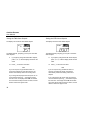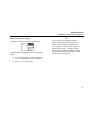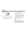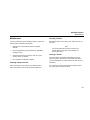
1
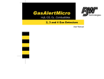
GasAlert Extreme
O2, CO, H2S, PH3, SO2, Cl2, NH3, NO2, HCN, ETO, ClO2, O3, or NO
Single Gas Detector
User Manual
D5561 English
iERP: 114642
© 2004 BW Technologies. All rights reserved. Printed in Canada.
All product names are trademarks of their respective companies.
Limited Warranty & Limitation of Liability
BW Technologies Ltd. (BW) warrants this product to be free from defects in material and workmanship under normal use and service for a period of two years, beginning on
the date of shipment to the buyer. This warranty extends only to the sale of new and unused products to the original buyer. BW’s warranty obligation is limited, at BW’s
option, to refund of the purchase price, repair, or replacement of a defective product that is returned to a BW authorized service center within the warranty period. In no event
shall BW’s liability hereunder exceed the purchase price actually paid by the buyer for the Product.
This warranty does not include:
a)
fuses, disposable batteries or the routine replacement of parts due to the normal wear and tear of the product arising from use;
b)
any product which in BW’s opinion, has been misused, altered, neglected or damaged by accident or abnormal conditions of operation, handling or use;
c)
any damage or defects attributable to repair of the product by any person other than an authorized dealer, or the installation of unapproved parts on the
product; or
The obligations set forth in this warranty are conditional on:
a)
proper storage, installation, calibration, use, maintenance and compliance with the product manual instructions and any other applicable recommendations
of BW;
b)
the buyer promptly notifying BW of any defect and, if required, promptly making the product available for correction. No goods shall be returned to BW
until receipt by the buyer of shipping instructions from BW; and
c)
the right of BW to require that the buyer provide proof of purchase such as the original invoice, bill of sale or packing slip to establish that the product is
within the warranty period.
THE BUYER AGREES THAT THIS WARRANTY IS THE BUYER’S SOLE AND EXCLUSIVE REMEDY AND IS IN LIEU OF ALL OTHER WARRANTIES, EXPRESS OR
IMPLIED, INCLUDING BUT NOT LIMITED TO ANY IMPLIED WARRANTY OF MERCHANTABILITY OR FITNESS FOR A PARTICULAR PURPOSE. BW SHALL NOT BE
LIABLE FOR ANY SPECIAL, INDIRECT, INCIDENTAL OR CONSEQUENTIAL DAMAGES OR LOSSES, INCLUDING LOSS OF DATA, WHETHER ARISING FROM
BREACH OF WARRANTY OR BASED ON CONTRACT, TORT OR RELIANCE OR ANY OTHER THEORY.
Since some countries or states do not allow limitation of the term of an implied warranty, or exclusion or limitation of incidental or consequential damages, the limitations and
exclusions of this warranty may not apply to every buyer. If any provision of this warranty is held invalid or unenforceable by a court of competent jurisdiction, such holding will
not affect the validity or enforceability of any other provision.
BW Technologies Ltd.
2840 – 2nd Ave. SE
Calgary, AB T2A 7X9
Canada
BW Technologies Inc. (America)
3279 West Pioneer Parkway
Arlington, TX 76013
USA
BW Europe Ltd.
101 Heyford Park,
Upper Heyford, Oxfordshire OX25 5HA
United Kingdom
Table of Contents
Title
Page
Introduction ......................................................................................................................................... 1
Contacting BW Technologies ............................................................................................................. 2
Safety Information - Read First........................................................................................................... 2
Getting Started.................................................................................................................................... 5
Activating the Detector ....................................................................................................................... 9
Self-Test ........................................................................................................................................ 9
Self-Test Pass ............................................................................................................................. 11
Self-Test Fail ............................................................................................................................... 11
Deactivating the Detector ................................................................................................................. 12
Confidence Beep .............................................................................................................................. 12
User Options Menu........................................................................................................................... 13
Exit Option ................................................................................................................................... 14
Date and Time Option ................................................................................................................. 14
Pass Code Protection Option ...................................................................................................... 15
Stealth Mode Option.................................................................................................................... 16
Automatic Backlight Option ......................................................................................................... 16
Latching Alarm Option................................................................................................................. 17
Automatic Oxygen Calibration Option ......................................................................................... 17
Calibration Past Protection Option .............................................................................................. 18
Languages Option ....................................................................................................................... 18
i
GasAlert Extreme
User Manual
Title
Page
Datalogger Sampling Rate Option...............................................................................................18
Data Transfer Option ...................................................................................................................19
Datalog and Event Log .....................................................................................................................20
Datalog ........................................................................................................................................20
Event Log.....................................................................................................................................21
Alarms...............................................................................................................................................22
Computed Gas Exposures ..........................................................................................................24
Viewing Gas Exposures ..............................................................................................................25
Gas Alarm Setpoints....................................................................................................................26
Resetting Gas Alarm Setpoints ...................................................................................................26
Stopping a Gas Alarm .................................................................................................................27
Sensor Alarm ...............................................................................................................................27
Low Battery Alarm .......................................................................................................................28
Automatic Shutdown Alarm .........................................................................................................28
Calibration and Setting Alarm Setpoints...........................................................................................29
Guidelines....................................................................................................................................29
Test Cap ......................................................................................................................................30
Calibration Procedure..................................................................................................................31
Maintenance .....................................................................................................................................39
Cleaning a Sensor Screen ..........................................................................................................39
Cleaning a Sensor .......................................................................................................................39
Clearing a Sensor........................................................................................................................39
Replacing the Battery or Sensor.......................................................................................................40
Troubleshooting ................................................................................................................................42
Replacement Parts and Accessories ...............................................................................................45
Specifications....................................................................................................................................46
General Specifications for Datalogger Units ....................................................................................47
ii
List of Tables
Table
Title
Page
1.
2.
3.
4.
5.
6.
7.
8.
9.
10.
11.
12.
13.
GasAlert Extreme Order Number................................................................................... ii
GasAlert Extreme Models .............................................................................................. 1
International Symbols .................................................................................................... 4
GasAlert Extreme Detector ............................................................................................ 6
Display Elements ........................................................................................................... 7
Pushbuttons ................................................................................................................... 8
Alarms .......................................................................................................................... 22
Computed Gas Exposures........................................................................................... 24
Gas Alarm Setpoints .................................................................................................... 26
Factory Alarm Setpoints............................................................................................... 26
Test Cap....................................................................................................................... 30
Replacing the Battery or Sensor .................................................................................. 41
Troubleshooting Tips ................................................................................................... 42
Replacement Parts and Accessories........................................................................... 45
iii
GasAlert Extreme
User Manual
iv
List of Figures
Figure
Title
Page
1.
2.
3.
4.
GasAlert Extreme Detector ............................................................................................ 6
Display Elements ........................................................................................................... 7
Test Cap....................................................................................................................... 30
Replacing the Battery or Sensor .................................................................................. 41
v
GasAlert Extreme
User Manual
Order Number
GAXT-X
GAXT-M2
Order Number
Description
Description
GasAlert Extreme O2
GAXT-E
GasAlert Extreme ETO
GasAlert Extreme CO
GAXT-V
GasAlert Extreme ClO2
GAXT-G
GasAlert Extreme O3
GAXT-N
GasAlert Extreme NO
(low H2 sensitivity)
GAXT-M
GasAlert Extreme CO
GAXT-H2
GasAlert Extreme H2S (high range)
GAXT-H
GasAlert Extreme H2S
GAXT-P
GasAlert Extreme PH3
GAXT-S
GasAlert Extreme SO2
GAXT-C
GasAlert Extreme Cl2
GAXT-A
GasAlert Extreme NH3
GAXT-D
GasAlert Extreme NO2
GAXT-Z
GasAlert Extreme HCN
Add –ML to the end of the order number for detectors with
the multi-language option.
Add –DL to the end of the order number for detectors with
the datalogging and multi-language option.
vi
GasAlert Extreme
Model
Introduction
aWarning
To ensure your personal safety, read “Safety
Information” before you use the detector.
GasAlert Extreme CO
GasAlert Extreme H2S
Gas Monitored
Carbon monoxide (ppm)
Hydrogen sulfide (ppm)
High range
GasAlert Extreme H2S
Hydrogen sulfide (ppm)
GasAlert Extreme PH3
Phosphine (ppm)
GasAlert Extreme SO2
Sulfur dioxide (ppm)
The detector is a personal safety device. It is your
responsibility to respond properly to the alarms.
GasAlert Extreme Cl2
Chlorine (ppm)
GasAlert Extreme NH3
Ammonia (ppm)
Table 1 lists the GasAlert Extreme models. This manual
includes examples from each model.
GasAlert Extreme NO2
Nitrogen dioxide (ppm)
The GasAlert Extreme gas detector (“the detector”) warns of
hazardous gas at levels above a factory set alarm setpoint.
This product is a gas detector, not a measurement device.
GasAlert Extreme HCN
Hydrogen cyanide (ppm)
Table 1. GasAlert Extreme Models
GasAlert Extreme ETO
Ethylene oxide (ppm)
Model
GasAlert Extreme ClO2
Chlorine dioxide (ppm)
Gas Monitored
GasAlert Extreme O2
Oxygen (% by volume)
GasAlert Extreme O3
Ozone (ppm)
GasAlert Extreme CO
Carbon monoxide (ppm)
GasAlert Extreme NO
Nitric oxide (ppm)
Low H2 sensitivity
1
GasAlert Extreme
User Manual
Contacting BW Technologies
Safety Information - Read First
To contact BW Technologies, call:
Use the detector only as specified in this manual, otherwise
the protection provided by the detector may be impaired.
USA: 1-888-749-8878
Canada: 1-800-663-4164
Europe: +44 (0) 1869 233004
Middle East: +971-4-8871766
China: +852-2974-1783
Australia: +61-7-3818-8244
Anywhere in the world: +1-403-248-9226
Address correspondence to:
BW Technologies Ltd.
2840 – 2 Avenue S.E.
Calgary, AB T2A 7X9
CANADA
Or visit us on the World Wide Web: www.gasmonitors.com
ISO 9001
2
International symbols used on the detector and in this manual
are explained in Table 2.
Read the Warnings and Cautions on the following pages
before using the detector.
c Note
This instrument contains a lithium battery. Do
not mix with the solid waste stream. Spent
batteries should be disposed of by a qualified
recycler or hazardous materials handler.
GasAlert Extreme
Safety Information - Read First
a Caution
To avoid possible personal injury:
⇒
Warning: Substitution of components may impair intrinsic safety.
⇒
Warning: To prevent ignition of flammable or combustible atmospheres, disconnect power before servicing.
⇒
Do not use the detector if it is damaged. Before you use the detector, inspect the case. Look for cracks or missing
plastic.
⇒
If the detector is damaged or something is missing, contact BW Technologies immediately.
⇒
Make sure the back is closed and fastened before you operate the detector.
⇒
Use only a sensor specifically designed for your GasAlert Extreme model. (See the section, Replacement Parts and
Accessories.)
⇒
Make sure the sensor screen is not blocked.
⇒
Periodically test the sensor’s response to gas by exposing the detector to a targeted gas concentration that
exceeds the high alarm setpoint. Manually verify that the audible and visual alarms are activated.
⇒
Calibrate the detector before first-time use, and then at least once every 180 days. (For HCN detectors, calibrate
once every 90 days.)
⇒
Do not turn off the detector during a work shift. Turning off the detector resets the TWA (time-weighted average),
STEL (short-term exposure limit), and maximum gas exposure values to 0. (See the section, Alarms.)
⇒
Use only the following battery: Energizer 1CR2. (See the section, Replacing the Battery or Sensor.)
⇒
To reduce the risk of ignition of a flammable atmosphere, batteries must only be changed in an area known to be
nonflammable.
3
GasAlert Extreme
User Manual
a Caution
To avoid possible damage to the detector:
⇒
Do not expose the detector to electrical shock and/or severe continuous mechanical shock.
⇒
Do not attempt to disassemble, adjust, or service the detector unless instructions for that procedure are contained
in the manual and/or that part is listed as a replacement part. Use only BW Technologies replacement parts.
⇒
The detector Warranty will be voided if customer personnel or third parties damage the detector during repair
attempts. Non-BW Technologies repair/service attempts void this Warranty.
⇒
The Oxygen GasAlert Extreme detector is classified by Underwriters Laboratories Inc. up to an atmosphere of 21%
Oxygen.
Table 2. International Symbols
Symbol
h
4
Meaning
Classified to both U.S. and Canadian Safety standards by Underwriter’s Laboratories, Inc.
X
Conforms to European Union Directives
g
European Explosives Protection
ATEX
Conforms to European ATEX Directives
IECEx
International Electrotechnical Commission Scheme for Certification to Standards for Electrical Equipment for
Explosive Atmospheres
GasAlert Extreme
Getting Started
Getting Started
The items listed below are included with your detector. If the
detector is damaged or something is missing, contact the
place of purchase immediately.
•
3 V lithium CR2-series battery.
•
GasAlert Extreme O2 model: O2 sensor;
GasAlert Extreme CO model: CO sensor (low H2
sensitivity);
GasAlert Extreme CO model: CO sensor;
GasAlert Extreme H2S model: H2S sensor (high range);
GasAlert Extreme H2S model: H2S sensor;
GasAlert Extreme PH3 model: PH3 sensor;
GasAlert Extreme SO2 model: SO2 sensor;
GasAlert Extreme Cl2 model: Cl2 sensor;
GasAlert Extreme NH3 model: NH3 sensor;
GasAlert Extreme NO2 model: NO2 sensor;
GasAlert Extreme HCN model: HCN sensor;
GasAlert Extreme ETO model: ETO sensor;
GasAlert Extreme ClO2 model: ClO2 sensor;
GasAlert Extreme O3 model: O3 sensor;
GasAlert Extreme NO model: NO sensor.
•
The detector comes with battery and sensor installed. To
order replacement parts and accessories, see the section,
Replacement Parts and Accessories.
To become familiar with the features and functions of the
detector, study the following figures and tables:
•
Figure 1 and Table 3 describe the detector’s
components.
•
Figure 2 and Table 4 describes the detector’s display
elements.
•
Table 5 describes the detector’s pushbuttons.
Test cap and hose.
5
GasAlert Extreme
User Manual
Table 3. GasAlert Extreme Detector
Item
Figure 1. GasAlert Extreme Detector
6
Function
A
Visual alarm
B
Display
C
Pushbuttons
D
Audible alarm
E
Sensor and sensor screen
F
Infrared communication port
G
Clip
GasAlert Extreme
Getting Started
Table 4. Display Elements
Item
Function
A
Numeric value
B
Gas cylinder
C
Automatic span sensor
D
Pass code lock
E
Set alarm setpoints and user options
F
Maximum gas exposure
G
Alarm conditions
H
Battery
Figure 2. Display Elements
I
Data transmission
Note
J
Alarm or alarm setpoint
The display backlight automatically activates for 3
seconds whenever there is insufficient light to view
the display (unless it is disabled in the user options)
and during alarm conditions. Any pushbutton
reactivates the backlight for 6 seconds.
K
Automatically zero sensor
L
Optional datalogger indicator
M
Parts per million (ppm)
N
Percentage by volume (% vol.)
O
Percentage by lower explosive limit (% LEL)
(future use)
7
GasAlert Extreme
User Manual
Table 5. Pushbuttons
Pushbutton
A
E
D
C
8
Description
•
To turn on the detector, press A.
•
To initiate the confidence beep, press A while pressing C at startup.
•
To turn off the detector, press A and hold for 5 seconds.
•
To decrement the displayed value, press E.
•
To enter the user options menu, press E and D simultaneously and hold for 5 seconds.
•
To initiate calibration and setting alarm setpoints, press and hold E and C simultaneously.
•
To increment the displayed value, press D.
•
To view the TWA, STEL and maximum gas exposures, press D and C simultaneously.
•
To save the displayed value, press C.
•
To clear TWA, STEL, and maximum gas exposures, press and hold C for 6 seconds.
GasAlert Extreme
Activating the Detector
Activating the Detector
4.
To activate the detector, press A.
The detector now tests the sensor. If the sensor
test fails, the audible alarm emits a slow
modulating tone, the visual alarm flashes slowly,
and the ALARM icon flashes.
The detector begins a self-test.
Self-Test
Once the detector is activated, it performs the following
checks. (Manually check that all actions occur.)
1.
The display shows all the elements.
2.
The audible alarm beeps, the visual alarm flashes,
the backlight briefly turns on, and the detector
emits one vibration.
The detector then conducts a battery test. If the
battery is too depleted to continue, the detector
performs an automatic shutdown. (Refer to the
Automatic Shutdown Alarm section.)
3.
If the sensor test passes, the self-test continues.
5.
The gas the detector measures appear on the
display.
If the battery is low, the display shows the low
battery icon and the self-test continues.
The display shows the date and time in the
following order: year, month, day of the month, day
of the week, and time.
9
GasAlert Extreme
User Manual
6.
The display shows the TWA alarm setpoint.
(Does not apply to O2.)
7.
The display shows the STEL alarm setpoint.
(Does not apply to O2.)
9.
The display shows the high alarm setpoint.
10. The display shows the calibration information.
Calibration Due Date
The display shows the following screens:
CAL. DUE XXX DAYS (where ‘XXX’ represents a number).
8.
10
The display shows the low alarm setpoint.
It shows the number of days that are left before you need to
calibrate your detector. Then the detector enters normal
operation.
GasAlert Extreme
Activating the Detector
Calibration Past Due
If the display shows the following screens:
If an incorrect pass code is entered, the detector
will shut down. If the correct pass code is entered,
the detector enters normal operation so a
calibration can be performed.
Self-Test Pass
It means the detector is past its calibration due date and it
needs to be calibrated before use.
If the detector passes the self-test, the detector begins
normal operation. The display then shows the ambient gas
reading:
If the calibration is past due, three outcomes could occur:
1.
2.
3.
The display toggles the screens CAL. PAST until it
is acknowledged by pressing C. The detector then
enters normal operation so a calibration can be
performed.
The display shows CAL. PAST and then performs
an automatic shutdown.
Press C within 5 seconds of the display showing
CAL. PAST. The display then requests the factory
pass code. (Refer to the Pass Code Protection
Option section.)
Then the detector starts recording the maximum gas
exposure and calculating the time-weighted average (TWA)
and short-term exposure limit (STEL).
Self-Test Fail
If the detector fails the self-test, see the Troubleshooting
section.
11
GasAlert Extreme
User Manual
Deactivating the Detector
Confidence Beep
To turn off the detector, press and hold A for 5 seconds.
The confidence beep tells you the battery has sufficient
power to appropriately respond to a hazardous level of gas
and emit an alarm. Instead of beeping when the battery’s
power is low, the audible alarm beeps to advise you the
battery has sufficient power. The confidence beep stops
when the battery power is low.
The audible alarm beeps four times and the visual alarm
flashes four times. The display then shows the following:
You can only activate the confidence beep at startup.
To turn on the confidence beep:
After 3 additional seconds, the display turns off and the
detector stops normal operation.
1.
If the detector is on, deactivate the detector.
2.
Press A while pressing C at startup.
Note
If A is held down for less than 5 seconds, the
detector will not shut down.
Upon startup, the detector continuously beeps once every 5
seconds.
To turn off the confidence beep, repeat steps 1 and 2 above.
12
GasAlert Extreme
User Options Menu
10. RATE: Adjust the datalogger sampling rate. (Only
applicable to detectors with the datalogger option.)
User Options Menu
The following are the available user options:
1.
EXIT: Exits the user options menu.
2.
CLCK: Adjust the date and time of the detector.
3.
PASS: Enable or disable pass code protection.
4.
STLH: Enable or disable stealth mode.
5.
BKLT: Enable or disable the automatic backlight
function. (When stealth mode is enabled, this
option is not available.)
6.
LTCH: Enable or disable the latching alarm
function.
7.
ACAL: Enable or disable the automatic Oxygen
calibration at startup. (Only available in the
GasAlert Extreme Oxygen detector.)
8.
PAST: Enable or disable automatic shutdown if
calibration is past its due date (at startup).
9.
PORT, ESPA, DEUT, FRAN, or ENGL: Enables
the display’s language in the user’s choice. (Only
applicable to detectors with the multi-language
feature.)
11. SEND: Transfers datalogs and event logs from the
detector to the PC. (Only applicable to detectors
with the datalogger option.)
To access the user options menu, press E and D
simultaneously until the display reads OPTN. Release the
buttons and one of the following screens appear:
•
PASS: Pass code
protection is on. Once you
enter the correct factory
pass code, the display will
show EXIT.
•
EXIT: Pass code protection
is off.
To scroll through the options, press E or D.
Note
If you do not press any pushbuttons within 20
seconds of entering the user options menu, the
detector returns to normal operation.
13
GasAlert Extreme
User Manual
Exit Option
To exit the options menu and
return to normal operation, press
C when the display reads EXIT.
Enter the current year. Press D to
scroll and C to confirm your
selection.
Enter the month. Press E and D
to scroll, and press C to confirm
your selection.
Date and Time Option
The date and time option allows your detector to track the
calibration due date and the datalogger information. Set the
date and time to your local settings.
To set the date and time, press C
when the display shows CLCK.
Enter the day. Scroll to the correct
day and press C to confirm your
selection.
Scroll to the correct day of the
week and press C to confirm your
selection.
Note
If you do not press any pushbuttons within 10
seconds of entering these displays, the detector
automatically retains the existing value.
If you change one of the values but pause for 10
seconds before pressing C, the detector rejects
the new value. The display shows NO the audible
and visual alarms beep and flash six times, and
the detector retains the original value.
14
This is a 24-hour clock. Enter the
hour and press C to confirm your
selection. Then enter the minutes
and press C to confirm your
selection.
Date and time settings are complete after your last
confirmation.
GasAlert Extreme
User Options Menu
Pass Code Protection Option
To Activate Pass Code Protection
Pass code protection prevents unauthorized personnel from
having access to the user options menu, calibration function,
and alarm setpoint adjust function.
As the PASS display is flashing, scroll to the correct pass
code and press C.
Note
If pass code protect is enabled, press E and D to scroll to
the correct pass code when the following screen appears.
The factory pass code is provided separately.
The next screen shows that you are about to set pass code
protection on. Press C to confirm.
Then press C to accept the displayed pass code.
The detector is shipped with the pass code protection off.
Entering the Pass Code Protect Option
To enter the pass code protection
option, press C when the display
reads PASS.
To Deactivate Pass Code Protection
If pass code protection is already activated, the following
screen appears after you enter the pass code option:
Press C to deactivate pass code protection.
15
GasAlert Extreme
User Manual
Stealth Mode Option
Automatic Backlight Option
Stealth mode disables the backlight and the audible and
visual alarms. The detector is shipped with stealth mode
disabled.
This option allows you to disable the automatic backlight of
the detector so regardless of the current lighting situation it
does not activate.
To enter the stealth mode option,
press C when the display shows
STLH.
The detector is shipped with the automatic backlight function
enabled.
To enter the automatic backlight
option, press C when the display
reads BKLT.
The display flashes ON if you are about to enable the
option, or OFF if you are about to disable the option. You
can toggle between ON and OFF by pressing E or D.
Then press C to confirm your selection.
The display then advises whether you are enabling (ON) or
disabling (OFF) the option. Press C to confirm your
selection.
If the option is enabled, the backlight automatically turns on
whenever there is insufficient light to view the display.
When stealth mode is enabled, STLH constantly appears on
the display unless the reading is not 0 ppm for toxics or
20.9% vol. for Oxygen.
Note
The vibrator alarm is disabled at -20°C.
16
If the option is disabled, you have to press C to turn on the
backlight if the detector is in low light conditions.
GasAlert Extreme
User Options Menu
Latching Alarm Option
Automatic Oxygen Calibration Option
The latching alarm option allows an alarm to remain active
until the user acknowledges the alarm by pressing C.
This option allows you to enable or disable the automatic
Oxygen calibration. Enabling this option allows the GasAlert
Extreme Oxygen detector to calibrate its sensor during
startup. (Sensor is calibrated after the display shows when
the next calibration is due.)
The detector is shipped with the latching alarm function
disabled.
To enter the latching alarm option,
press C when the display reads
LTCH.
The display advises whether you are enabling or disabling
the latching alarm function. Press C to confirm your
selection.
The detector is shipped with this function disabled.
To enter the automatic Oxygen
calibration option, press C when
the display reads ACAL.
The display then advises whether you are enabling (ON) or
disabling (OFF) the option. Press C to confirm your
selection.
17
GasAlert Extreme
User Manual
Calibration Past Protection Option
This option allows you to enable an automatic shutdown at
startup if the detector is past due for a calibration.
The detector is shipped with English as the language
default.
Scroll to the appropriate language and press C to confirm
your choice.
The detector is shipped with this option disabled.
Datalogger Sampling Rate Option
To enter the calibration past
protection option, press C when
the display reads PAST.
The detector is shipped with the datalogger set to record a
sample every 5 seconds. This sample rate can be from 1 to
60 seconds.
The display then advises whether you are enabling (ON) or
disabling (OFF) the option. Press C to confirm your
selection.
Languages Option
If your detector has the multi-language feature, you can
choose to view your display in the following five languages:
•
Portuguese (PORT);
•
Spanish (ESPA);
•
German (DEUT);
•
French (FRAN); and
•
English (ENGL).
18
To adjust the datalogger sampling
rate, press C when the display
shows RATE.
Use E and D to change the
sampling rate and then press C
to confirm your selection.
GasAlert Extreme
User Options Menu
Data Transfer Option
This option transfers the datalog/event log information from
the detector to the PC.
Once you select one of the three options, the display will
administer a countdown to indicate that the data is
transferring.
Note
You need an IR DataLink (or other BW accessory)
in order to transfer the data from the detector to
the PC.
To enter the data transfer option,
press C when the display shows
SEND.
Once you are inside this option you can transfer the
information in one of the following three ways:
•
EVNT: Transfers all of the events.
•
LAST: Sends all of the datalogs since the last time
they were downloaded.
•
ALL: Sends all of the datalogs saved on the detector.
The number that the countdown begins at is dependant
upon the amount of data that is being transferred.
Note
When you transfer event logs nothing appears on
the display to indicate it is transferring because
there is little data to transfer.
After the transfer is complete, the display reads EXIT.
19
GasAlert Extreme
User Manual
If the connection between the detector and the IR DataLink
is disturbed during a transfer, the following display appears
before exiting to the user options menu.
Datalog and Event Log
The GasAlert Extreme datalogger version allows the
detector to record various information so a report can be
compiled.
Datalog
Note
If the transfer fails, selecting LAST will resume the
transfer from where the initial send failed. To
ensure that you do not delete the previously
transferred data, either save the already
transferred data before selecting LAST, or select
ALL to ensure the previously downloaded data is
transferred again.
20
Datalog information is recorded based on the sampling rate
set in the detector’s user options. The following information
is recorded in a datalog:
•
The date and time;
•
The detector’s serial number;
•
The type of gas the detector monitors;
•
The current gas reading;
•
The sensor status;
•
The unit status;
•
Pass code protect is on/off;
GasAlert Extreme
Datalog and Event Log
•
The period that STEL is calculated;
Event Log
•
Confidence beep is on/off;
•
Automatic backlight is on/off;
An event log is data which is recorded when an event (i.e.,
an alarm) occurs. The following information is recorded in an
event log:
•
Stealth mode is on/off;
•
The detector’s serial number;
•
Latching alarm is on/off;
•
The type of exposure the detector experienced;
•
The calibration past user option is on/off; and
•
The time the alarm started and ended; and
•
The language that the display is shown at.
•
The peak exposure of the alarm.
21
GasAlert Extreme
User Manual
Alarms
Table 7 describes the computed gas exposures.
Table 6 describes detector alarms and shows how the
display looks for each alarm.
Table 6. Alarms
Alarm
Display
Alarm
Low Alarm:
TWA Alarm:
•
•
•
•
•
•
•
•
Slow modulating tone
Slow flash
ALARM flashes
Slow vibrations
Slow modulating tone
Slow flash
ALARM flashes
Slow vibrations
High Alarm:
STEL Alarm:
•
•
•
•
•
•
•
•
Fast modulating tone
Fast flash
ALARM flashes
Fast vibrations
Fast modulating tone
Fast flash
ALARM flashes
Fast vibrations
Sensor Alarm:
Low Battery Alarm:
•
•
•
•
• 1 beep, 1 flash every 5 seconds
and 1 quick vibration every
minute (confidence beep
disabled)
• No beeps, flashes, or vibrations
(confidence beep enabled)
22
Slow modulating tone
Slow flash
ALARM flashes
Slow vibrations
Display
GasAlert Extreme
Alarms
Table 6. Alarms (cont.)
Alarm
Display
Alarm
Automatic Shutdown Alarm:
(Low battery)
•
Automatic Shutdown Alarm:
(Calibration past)
•
8 beeps, flashes, and
vibrations
LOW displays
After Automatic Shutdown:
(Low battery)
Confidence Beep:
•
•
No modulating tone
No flash or vibrations
displays for a short time
1 beep every 5 seconds
1 quick vibration per
minute
I
•
•
•
8 beeps, flashes, and
vibrations
I
•
Display
Note
During an alarm condition, the detector activates the backlight and the display shows the current ambient gas reading.
The high alarm and STEL alarm have the same priority. A high alarm and/or STEL alarm override a low alarm and/or TWA
alarm. To check STEL and TWA alarms specifically, press and hold C and D simultaneously.
The vibrator alarm is disabled at -20°C.
23
GasAlert Extreme
User Manual
Table 7. Computed Gas Exposures
Computed Gas Exposures
a Warning
To avoid possible personal injury, do not turn
off the detector during a work shift. The
detector automatically resets the TWA, STEL,
and maximum gas exposures at startup. If you
restart the detector during a work shift, these
values will not reflect the entire work shift.
Gas Exposure
TWA
Description
•
•
STEL
•
•
Maximum*
•
Time-weighted average based
on an 8-hour workday.
Accumulated value.
Time-weighted average based
on a 15-minute period.
Accumulated value.
Highest gas level encountered
during the period the detector is
turned on.
*Maximum gas exposure for Oxygen describes the
furthest level reached from 20.9% vol.
24
GasAlert Extreme
Alarms
Viewing Gas Exposures
Toxic Gases
Press C and D simultaneously and the display first shows
the TWA gas exposure.
Press C and hold for 6 seconds to clear the TWA, STEL,
and maximum gas exposure. The detector emits two beeps
and two vibrations to confirm that the exposures have been
cleared.
Oxygen
If you have an Oxygen detector, pressing C and D
simultaneously displays both the very low and very high
levels of Oxygen exposure.
The display then shows the STEL gas exposure.
The display then shows the maximum gas exposure.
25
GasAlert Extreme
User Manual
Resetting Gas Alarm Setpoints
Gas Alarm Setpoints
The detector’s gas alarm setpoints trigger the gas alarms
described in the table below.
Table 8. Gas Alarm Setpoints
Alarm
TWA above TWA alarm setpoint.
(O2: Not applicable)
STEL Alarm
STEL above STEL alarm setpoint.
(O2: Not applicable)
Low Alarm
Toxic Gases: Ambient gas level
above low alarm setpoint.
Table 9 lists the factory alarm setpoints.
Table 9. Factory Alarm Setpoints
Gas
TWA
STEL
Low
High
O2
N/A
N/A
19.5% vol.
22.5% vol.
CO (low H2)
35 ppm
200 ppm
35 ppm
200 ppm
CO
35 ppm
200 ppm
35 ppm
200 ppm
H2S
10 ppm
15 ppm
10 ppm
15 ppm
(high range)
O2: Ambient gas level may be set
to above or below 20.9%.
H2S
10 ppm
15 ppm
10 ppm
15 ppm
PH3
0.3 ppm
1.0 ppm
0.3 ppm
1.0 ppm
Ambient gas level above high
alarm setpoint.
SO2
2.0 ppm
5.0 ppm
2.0 ppm
5.0 ppm
Cl2
0.5 ppm
1.0 ppm
0.5 ppm
1.0 ppm
NH3
25 ppm
35 ppm
25 ppm
50 ppm
NO2
2.0 ppm
5.0 ppm
2.0 ppm
5.0 ppm
HCN
4.7 ppm
10.0 ppm
4.7 ppm
10.0 ppm
ETO
1.0 ppm
5.0 ppm
1.0 ppm
5.0 ppm
O2: Ambient gas level may be set
to above or below 20.9%.
26
Standard factory alarm setpoints vary by region.
Condition
TWA Alarm
High Alarm
Note
GasAlert Extreme
Alarms
Gas
TWA
STEL
Low
High
ClO2
0.10 ppm
0.30 ppm
0.10 ppm
0.30 ppm
O3
0.10 ppm
0.10 ppm
0.10 ppm
0.20 ppm
NO
25 ppm
25 ppm
25 ppm
25 ppm
To change the factory alarm setpoints, refer to the section
Calibration and Setting Alarm Setpoints.
Note
You can disable an alarm by setting the alarm
setpoint to 0.
The ETO sensor is extremely cross sensitive and it
responds strongly to CO.
Stopping a Gas Alarm
The low and high alarms stop when the ambient gas level
returns to the acceptable range.
The detector computes the TWA and STEL value. If the
value is above the alarm setpoint, the detector activates to
TWA and/or the STEL alarm. To stop the TWA and/or STEL
alarm, press and hold C for 6 seconds, or deactivate the
detector.
Acknowledge Latched Alarm
If an alarm is set to latch, the audible and visual alarms
persist in the event of an alarm condition until it is
acknowledged.
To acknowledge a latched alarm condition, press C to reset
the latched alarm when the gas level present has dropped
below the alarm setpoint.
Sensor Alarm
The detector tests for a missing or defective sensor during
the activation self-test. See the Troubleshooting section.
27
GasAlert Extreme
User Manual
Low Battery Alarm
Automatic Shutdown Alarm
The detector tests the battery during the activation self-test
and continuously thereafter. If the battery voltage is low, the
detector activates the low battery alarm.
There are two situations where an automatic shutdown alarm
occurs:
1.
The low battery alarm continues until you replace the battery
or the battery power is almost depleted. If the battery voltage
drops too low, the detector executes an automatic shutdown.
If the confidence beep is on, the audible alarm does
not beep during a low battery alarm. See the
Confidence Beep section.
For directions on how to replace the battery, see
the section Replacing the Battery or Sensor.
Note
Typically, the low battery alarm continues for 30
minutes before an automatic shutdown.
2.
28
If the calibration past protection user option is
active and the detector is past its calibration due
date, the detector will go into an automatic
shutdown.
I
Note
If the battery voltage is in immediate danger of
dropping below the minimum operating voltage, the
audible alarm beeps 8 times, the visual alarm
flashes 8 times, and the detector emits 8 vibrations.
After 3 seconds, the display blanks out and the
detector stops normal operation. The display shows
periodically until the battery power is depleted.
GasAlert Extreme
Calibration and Setting Alarm Setpoints
Calibration and Setting Alarm Setpoints
•
Calibration accuracy is never better than the calibration
gas accuracy. BW Technologies recommends a
premium grade calibration gas. Gases with NIST
(National Institute of Standards and Technology)
traceable accuracy will improve the validity of the
calibration. Do not use a gas cylinder beyond its
expiration date.
•
Calibrate a new sensor before use. Allow the sensor to
stabilize before starting calibration (used: 60 seconds;
new: 5 minutes).
•
Calibrate the detector at least once every 180 days (for
HCN detectors calibrate at least once every 90 days),
depending on use and sensor exposure to poisons and
contaminants.
•
Calibrate the detector if the ambient gas display varies
at startup.
•
It is best to calibrate the sensor before changing the
alarm setpoints.
•
Calibrate only in a clean atmosphere, which is free of
background gas.
•
To disable an alarm, set its alarm setpoint to 0.
•
If you require a certified calibration, contact
BW Technologies.
Guidelines
When calibrating the detector, adhere to the following
guidelines.
•
•
•
Recommended gas mixture:
O2: Clean Air, 20.9% vol.
CO (low H2 sensitivity): 50 to 500 ppm balance N2
CO: 50 to 500 ppm balance N2
H2S (high range): 10 to 100 ppm balance N2
H2S: 10 to 100 ppm balance N2
PH3: 1 to 5 ppm balance N2
SO2: 10 to 50 ppm balance N2
Cl2: 3 to 25 ppm balance N2
NH3: 20 to 100 ppm balance N2
NO2: 5 to 50 ppm balance N2
HCN: 5 to 20 ppm balance N2
ETO: 5 to 50 ppm balance N2
ClO2: 0.1 to 1.0 ppm balance N2
O3: 0.1 to 1.0 ppm balance N2
NO: 10 to 250 ppm balance N2
For ETO detectors (before each use) allow the
instrument to fully stabilize in the temperature that it is to
be operated in and then zero the detector.
It is necessary to periodically re-zero the ETO detector.
29
GasAlert Extreme
User Manual
Test Cap
The test cap and hose, which are shipped with the detector,
simplify the sensor testing and calibration. Table 10 and
Figure 3 show how to use the test cap and hose when
applying gas to the sensor.
Table 10. Test Cap
Item
Description
A
Test cap
B
Hose
C
Regulator and gas cylinder
Figure 3. Test Cap
30
GasAlert Extreme
Calibration and Setting Alarm Setpoints
Auto Zero
Calibration Procedure
To calibrate the detector and set its alarm setpoints, perform
the following procedure.
2.
The display flashes AUTO-ZERO while the detector
automatically zeroes the sensor.
Note
To quit at any point, press A. The detector retains
any saved values and emits four beeps and four
vibrations before returning to normal operation.
Calibrate O2 in clean air.
Start Calibration
1.
Press C and E simultaneously until the display
shows the following.
The audible alarm beeps once.
The audible alarm then beeps twice.
Note
Do not apply the calibration gas until the display
shows a flashing gas cylinder; otherwise, the auto
zero step will fail.
If the sensor fails the auto zero step, the display
shows FAIL, the detector skips the sensor span
steps and goes to the alarm setpoints. Press A to
exit. Then restart calibration in an atmosphere that
is clear of the targeted gas. If the step fails a
second time, restart the detector to test the
sensors.
31
GasAlert Extreme
User Manual
Pass Code Protect Activated
After a successful auto zero, the detector asks for the pass
code if the detector is pass code protected. The pass code
needs to be entered before proceeding to auto span and
alarm setpoints.
3.
The display will advise calibration is locked. It then
requests the pass code. (Refer to Pass Code
Protection Option.)
Note
If the correct code is entered, the detector beeps
twice and automatically proceeds to set span.
If the pass code is not entered within 10 seconds or
the wrong pass code is entered, the detector
displays NO.
The detector then beeps four times and
automatically returns to normal operation.
32
GasAlert Extreme
Calibration and Setting Alarm Setpoints
Set Span
The display shows the current calibration gas setting.
The display flashes prompting you to input a new calibration
gas concentration, or you can accept the current value for the
span (sensitivity adjustment).
4.
To change the calibration gas setting, press D or
E until the display matches the concentration of
the calibration gas.
5.
Press C to save the new value.
Note
If you do not press any pushbuttons within 10
seconds of viewing this display, the detector
automatically saves the displayed concentration of
the calibration gas.
If you change the calibration gas concentration but
pause for 10 seconds before pressing C, the
detector rejects the new value. The display shows
NO, the audible alarm beeps six times, and the
detector retains the original value.
33
GasAlert Extreme
User Manual
Span
The display now shows a flashing gas cylinder prompting you
to apply a calibration gas to the sensor or you can skip the
span.
NH3, Cl2, ClO2, O3, and ETO: 5 minutes; O2: 30 seconds;
other gases: 2 minutes (approximately).
The audible alarm beeps three times at the end of the span.
Note
The detector will not span a sensor if:
•
You do not apply gas to the sensor.
•
The sensor fails to detect at least a quarter of
the expected gas concentration in the first 30
seconds.
•
The gas concentration drops below one-half of
the expected gas level during the 2-minute
span.
Note
If you skip the span, you cannot change the
calibration date.
The flashing gas cylinder does not appear if you
have an Oxygen detector.
6.
Apply gas to the sensor at a flow rate of 500
ml/min.
(for NH3, Cl2, and ETO: 1000 ml/min.)
OR
Press C to skip the span.
The gas reading will change as gas is applied to the sensor.
When the detector senses approximately a quarter of the
expected gas concentration (30 seconds), the audible alarm
beeps once. The detector then begins spanning the sensor.
34
If the detector fails to span a sensor, the display
shows FAIL and the audible and visual alarms
beep and flash six times (unless you pressed C to
skip the span). You then proceed to the alarm
setpoints.
If you apply gas to a sensor and the detector fails to
span the sensor, press A to exit the calibration and
repeat the calibration process using a new gas
cylinder. If the sensor fails the span a second time,
replace the sensor. (See the section, Replacing the
Battery or Sensor.)
GasAlert Extreme
Calibration and Setting Alarm Setpoints
Setting the Calibration Due Date
After a successful calibration, the display shows the number
of days remaining before the next calibration is due. (The
default setting is 180 days.)
The display flashes prompting you to change the calibration
due date between 1 and 365 days.
7.
If you want to change the next calibration due date,
press D or E until the display shows the new
value.
8.
Press C to save the new value.
Note
If you do not press any pushbuttons within 10
seconds of entering this display, the detector
automatically retains the existing value.
35
GasAlert Extreme
User Manual
Setting the TWA Alarm Setpoint
Setting the STEL Alarm Setpoint
The display now shows the TWA alarm setpoint.
The display shows the STEL alarm setpoint.
The display flashes, prompting you to input a new TWA
alarm setpoint.
The display flashes prompting you to input a new STEL
alarm setpoint.
9.
If you want to change the TWA alarm setpoint,
press D or E until the display shows the new
value.
10. Press C to save the new value.
Note
If you do not press any pushbuttons within 10
seconds of entering the TWA alarm display, the
detector automatically retains the existing value.
If you change the displayed value but pause for 10
seconds before pressing C, the detector rejects
the new value. The display shows NO, the audible
and visual alarms beep and flash six times, and the
detector retains the original value.
36
11. If you want to change the STEL alarm setpoint,
press D or E until the display shows the new
value.
12. Press C to save the new value.
Note
If you do not press any pushbuttons within 10
seconds of viewing this display, the detector
automatically retains the existing STEL alarm
setpoint.
If you change the STEL alarm value but pause for
10 seconds before pressing C, the detector rejects
the new value. The display shows NO, the audible
and visual alarms beep and flash six times, and the
detector retains the original value.
GasAlert Extreme
Calibration and Setting Alarm Setpoints
Setting the Low Alarm Setpoint
The display now shows the current low alarm setpoint.
The display flashes prompting you to input a new low alarm
setpoint.
Note
If you do not press any pushbuttons within 10
seconds of entering the low alarm display, the
detector automatically retains the existing value.
If you change the low alarm value but pause for 10
seconds before pressing C, the detector rejects
the new value. The display shows NO, the audible
and visual alarms beep and flash six times, and the
detector retains the original value.
13. If you want to change the low alarm setpoint, press
D or E until the display shows the new value.
14. Press C to save the new value.
37
GasAlert Extreme
User Manual
Setting the High Alarm Setpoint
The display shows the high alarm setpoint.
The display flashes prompting you to input a new high alarm
setpoint.
15. If you want to change the high alarm setpoint, press
D or E until the display shows the new value.
16. Press C to save the new value.
Note
If you do not press any pushbuttons within 10
seconds of viewing this display, the detector
automatically retains the existing high alarm
setpoint.
If you change the high alarm setpoint but pause for
10 seconds before pressing C, the detector rejects
the new value. The display shows NO, the audible
and visual alarms beep and flash six times, and the
detector retains the original value.
At the end of the calibration procedure the audible alarm
beeps four times and the detector returns to normal
operation.
Verification
After calibration is complete and the unit is in normal
operating mode, test the detector using a gas cylinder other
than the one used in calibration. The gas concentration
should not exceed the sensor's detection range. Confirm that
the display shows the expected concentration.
38
GasAlert Extreme
Maintenance
Maintenance
Cleaning a Sensor
To keep the detector in good operating condition, perform the
following basic maintenance as required:
Remove the sensor. Clean using a soft, clean brush. Do not
use water.
•
Calibrate, test, and inspect the detector at regular
intervals.
•
Keep an operations log of all maintenance, calibrations,
and alarm events.
•
Clean the exterior with a soft damp cloth. Do not use
solvents, soaps, or polishes.
Note
It is recommended that you apply a test gas and
test the detector’s response to gas following any
cleaning procedure.
Clearing a Sensor
Cleaning a Sensor Screen
The sensor has a high degree of resistance to common
vapors and gases. The sensor will most likely clear itself if
you move the detector to a clean environment and wait 10 to
30 minutes.
Remove the screen. Clean using a soft, clean brush and
clean, warm water. Let the screen dry before replacing it.
Do not expose a sensor to the fumes of inorganic solvents
(e.g., paint fumes) or organic solvents.
•
Do not immerse the detector in liquids.
39
GasAlert Extreme
User Manual
Replacing the Battery or Sensor
a Warning
To avoid possible personal injury:
Replace the battery as soon as the detector
emits a low battery alarm.
Figure 4 and Table 11 illustrate how to replace the battery or
sensor. If the detector is on, shut down the detector before
replacing the battery or sensor. Use a Phillips head
screwdriver to loosen and tighten any screws.
Do not use excessive force when removing or inserting the
sensor, or the sensor can be damaged. Gently rocking the
sensor back and forth may help free a tightly held sensor.
Use only the Energizer 1CR2 battery.
Use only the sensor specifically designed for
your GasAlert Extreme model. Otherwise, the
detector will not monitor the target gas. (See
the section, Replacement Parts and
Accessories.)
Note
When you remove the battery from the detector, the
clock will revert back to its default value.
To preserve battery life, turn the detector off when you are
not using it.
40
When placing the sensor screen back, ensure that the shiny
side is facing away from the sensor.
The sensor provides consistent and accurate ambient gas
readings. The sensor lasts 2 years under normal operation.
After replacing a sensor or battery, ensure that the detector’s
back screws are torque to 3-4 in-lbs in a crisscross pattern to
ensure a proper environment seal.
The Troubleshooting section describes the problems caused
by a sensor in need of calibration or replacement.
GasAlert Extreme
Replacing the Battery or Sensor
Table 11. Replacing the Battery or Sensor
Item
Description
A
Detector back screws
B
Detector back
C
Battery
D
Main board screws
E
Main board
F
Sensor
G
Detector front
H
Sensor screen
Figure 4. Replacing the Battery or Sensor
41
GasAlert Extreme
User Manual
The detector’s electronics are protected from variations in
humidity and corrosive atmospheres. If you encounter a
problem, try the solutions listed in the following table.
Troubleshooting
This section describes the various problems you may
encounter with your detector and how you can fix those
problems.
If you still are unable to correct the problem, contact BW
Technologies.
Table 12. Troubleshooting Tips
Problem
The detector does not turn on.
The detector enters alarm mode
immediately when it is turned on.
42
Possible Cause
Solution
→
No battery
→
Install battery
→
Depleted battery
→
Replace battery
→
Damaged or defective detector
→
Contact BW
→
Reversed battery
→
Reinstall battery correctly
→
Sensor needs to stabilize
→
Used sensor: wait 60 seconds
New sensor: wait 5 minutes
→
Low Battery alarm
→
Replace battery
→
Sensor alarm
→
Replace sensor
GasAlert Extreme
Troubleshooting
Table 12. Troubleshooting Tips (cont.)
Problem
Possible Cause
Solution
The activation self-test fails during one
of the checks.
→
General fault
→
Contact BW
→
Alarm setpoints are incorrect
→
Reset alarm setpoints
The detector does not display normal
ambient gas reading after activation
self-test.
→
Sensor not stabilized
→
Used sensor: wait 60 seconds
New sensor: wait 5 minutes
→
Detector requires calibration
→
Calibrate detector
→
Targeted gas is present
→
Detector is operating properly. Use
caution in suspect areas.
The detector does not respond to the
pushbuttons.
→
Battery is depleted
→
Replace battery
→
Detector is performing operations
that do not require user input
→
Pushbutton operation restores
automatically when the operation
ends
The detector does not accurately
measure the gas.
→
Detector requires calibration
→
Calibrate sensor
→
Detector is colder/hotter than
ambient gas
→
Allow detector to acquire ambient
temperature before use
→
Sensor screen is blocked
→
Clean sensor screen
43
GasAlert Extreme
User Manual
Table 12. Troubleshooting Tips (cont.)
Problem
Possible Cause
Solution
→
Alarm setpoint(s) are set incorrectly
→
Reset alarm setpoints
→
Alarm setpoint(s) set to zero
→
Reset alarm setpoints
→
Detector is in calibration mode
→
Complete the calibration procedure
→
Ambient gas levels are near alarm
setpoint or the sensor is exposed to a
puff of the targeted gas
→
Detector is operating normally. Use
caution in suspect areas. Check
maximum gas exposure reading.
→
Alarms set incorrectly
→
Reset alarm setpoints
→
Missing or faulty sensor
→
Replace sensor
The detector automatically shuts off.
→
Automatic shutdown feature activated
due to weak battery
→
Replace battery
Unit will not auto zero or calibrate; O2
sensor reading is erratic.
→ Sensor may be expired
→
Change the sensor
The detector does not enter alarm.
The detector intermittently enters
alarm without apparent reason.
44
GasAlert Extreme
Replacement Parts and Accessories
Model No.
Replacement Parts and Accessories
a Warning
To avoid personal injury or damage to the
detector, use only specified replacement parts.
To order any parts or accessories, contact BW Technologies.
Table 13. Replacement Parts and Accessories
Model No.
Description
Qty
Description
Qty
SR-G04
Replacement O3 sensor
1
SR-N04
Replacement NO sensor
1
GA-SS
Sensor screens
10
GA-TC-1
Test cap and hose
1
GA-HC-1
Hard hat clip
1
GA-AG-1
Alligator clip (non-conductive)
1
GA-AG-2
Alligator clip (stainless-steel)
1
REG-0.5
Gas regulator (0.5 L/min)
1
G0042-H25
Calibration gas, H2S (58 L)
1
CG2-M-200-103
Calibration gas, CO (103 L)
1
SR-X10
Replacement O2 sensor
1
SR-M204
Replacement CO (low H2
sensitivity) sensor
1
PS-RM04
Replacement CO sensor
1
CG2-S-25
Calibration gas, SO2 (58 L)
1
PS-RH04S
Replacement H2S sensor
1
CG2-C-5
Calibration gas, Cl2 (58 L)
1
SR-P04
Replacement PH3 sensor
1
CG2-Z-10
Calibration gas, HCN (58 L)
1
PS-RS04
Replacement SO2 sensor
1
CG2-D-10
Calibration gas, NO2 (58 L)
1
PS-RC10
Replacement Cl2 sensor
1
CG2-P-1-58
Calibration gas, PH3 (58 L)
1
SR-A04
Replacement NH3 sensor
1
GA-USB2
IR DataLink
1
PS-RD04
Replacement NO2 sensor
1
PS-RZ10
Replacement HCN sensor
1
SR-E04
Replacement ETO sensor
1
SR-V04
Replacement ClO2 sensor
1
45
GasAlert Extreme
User Manual
Specifications
Sensor type: Plug-in electrochemical cells
Operating temperature:
H2S, SO2, HCN: -40°C to +50°C (-40°F to +122°F)
CO: -30°C to +50°C (-22°F to +122°F)
Other gases: -20°C to +50°C (-4°F to +122°F)
Calibration: Auto zero, set span, and span sensor
Operating humidity:
CO, H2S, SO2, Cl2, HCN, NO2, NH3, PH3, ETO, NO, O3:
15% to 90% relative humidity (non-condensing)
Cl2: 10% to 95% relative humidity (non-condensing)
ClO2: 15% to 95% relative humidity (non-condensing)
O2: 0% to 99% relative humidity (non-condensing)
Audible alarm: 95 dB at 1 ft. (0.3 m) typical
Detection ranges:
GasAlert Extreme O2: 0 – 30.0% vol. (0.1% vol. increments)
GasAlert Extreme CO (low H2 sensitivity): 0 – 1000 ppm
(1 ppm increments)
GasAlert Extreme CO: 0 – 1000 ppm (1 ppm increments)
GasAlert Extreme H2S (high range): 0 – 500 ppm
(1 ppm increments)
GasAlert Extreme H2S: 0 – 100 ppm (1 ppm increments)
GasAlert Extreme PH3: 0 – 5.0 ppm (0.1 ppm increments)
GasAlert Extreme SO2: 0 – 100.0 ppm (0.1 ppm increments)
GasAlert Extreme Cl2: 0 – 50.0 ppm (0.1 ppm increments)
GasAlert Extreme NH3: 0 – 100 ppm (1 ppm increments)
GasAlert Extreme NO2: 0 – 100.0 ppm (0.1 ppm increments)
GasAlert Extreme HCN: 0 – 30.0 ppm (0.1 ppm increments)
GasAlert Extreme ETO: 0 – 100.0 ppm (0.1 ppm increments)
GasAlert Extreme ClO2: 0 – 1 ppm (0.01 ppm increments)
GasAlert Extreme O3: 0 – 1 ppm (0.01 ppm increments)
GasAlert Extreme NO: 0 – 250 ppm (1 ppm increments)
46
Alarm conditions: TWA alarm, STEL alarm, low alarm, high
alarm, sensor alarm, low battery alarm, confidence beep,
automatic shutdown alarm
Visual alarm: Red light-emitting diode (LED)
Display: Alpha-numeric liquid crystal display (LCD)
Backlight: Automatically activates for 3 seconds whenever
there is insufficient light to view the display and during alarm
conditions. Any pushbutton reactivates the backlight for 6
seconds.
Self-test: Initiated at activation
Battery test: Every 0.5-second
Battery: 3 V lithium Energizer 1CR2-series battery
Intrinsic safety:
Classified by UL to both U.S. and Canadian Standards as
intrinsically safe for Class I, Division 1, Group A, B, C, D
European Explosives Protection EEx ia IIC
CE 0539 g II 2 G DEMKO 04 ATEX 03 36363
CE g II 1 G EEx ia IIB T4
IECEx
GasAlert Extreme
General Specifications for Datalogger Units
General Specifications for Datalogger
Units
Storage: Maximum of 8 months of data at 5-second intervals
(based on a normal workweek).
Memory Type: Wrap-around memory ensures most recent
data is always saved.
Sample Rate: One reading every 5 seconds (standard).
Data Recorded: All sensor readings, all alarm conditions,
calibrations, event flags, battery status, sensor status,
confidence beep activation, and detector status along with
the time and date and the unit’s serial number.
Indicators: Icon advising Datalogger is operating normally.
Transfer Accessory: IR DataLink or other BW accessory.
Support:
BW E.D.M. (Excel Datalog Manager): This software
organizes GasAlert Extreme datalog and event log files into a
readable report.
47
GasAlert Extreme
O2, CO, H2S, PH3, SO2, Cl2, NH3, NO2, HCN, ETO, ClO2, O3, or NO
Single Gas Detector
User Manual
D5561/3 English
iERP: 116330
© 2004 BW Technologies. All rights reserved. Printed in Canada.
All product names are trademarks of their respective companies.