1
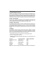
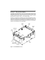
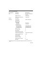
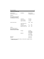
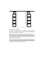
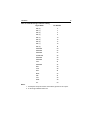
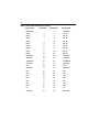
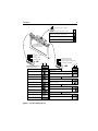
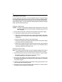
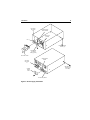
.............................
Elite Disc Drive
.............................
ST43400N/ND
.............................
.............................
User’s Manual
.............................
ii
Contents
Preface ....................................................................................................
Electrostatic discharge protection ........................................................
Important safety information and precautions ......................................
Technical support services ..................................................................
Section 1. General description ................................................................
Section 2. Installation ..............................................................................
Section 3. Operation ...............................................................................
Section 4. Parts data ...............................................................................
Section 5. Maintenance ...........................................................................
iii
iii
iv
vi
1
7
33
37
39
© 1992 Seagate Technology, Inc. All rights reserved
Publication Number: 83327630, Rev. A
Seagate® , Seagate Technology® , and the Seagate logo are registered
trademarks of Seagate Technology, Inc. EliteTM, SeaFAXTM, SeaFONETM, and
SeaBOARDTM are trademarks of Seagate Technology, Inc. Other product
names are registered trademarks or trademarks of their owners.
No part of this publication may be reproduced in any form without written
permission from Seagate Technology, Inc.
ST43400N/ND User’s Manual
iii
Preface
This manual contains information for users of the Seagate ST43400N and
ST43400ND Elite disc drives employing the SCSI interface. It provides installation, operation, and maintenance information. This manual also lists the part
numbers for options and accessories available for these drives. Additional
information is available in the reference manual (publication 83327640).
Electrostatic discharge protection
Caution. Removal of circuit boards by personnel not performing depot repair
will damage components and may void the warranty.
All drive electronic assemblies are sensitive to static electricity, due to the
electrostatically sensitive devices used within the drive circuitry. Although
some devices such as metal-oxide semiconductors are extremely sensitive,
all semiconductors, as well as some resistors and capacitors, may be
damaged or degraded by exposure to static electricity.
Electrostatic damage to electronic devices may be caused by the direct
discharge of a charged conductor or by exposure to the static fields surrounding charged objects. To avoid damaging drive electronic assemblies, observe the following precautions when installing or servicing the drive:
• Ground yourself to the drive whenever the drive electronics are or will be
exposed. Connect yourself to ground with a wrist strap (refer to accessories
in Section 4 for part numbers). Connection may be made to any grounded
metal assembly. As a general rule, remember that you and the drive electronics must all be grounded to avoid potentially damaging static discharges.
• Turn off the power before removing or installing the DC power cable.
• Do not remove any circuit boards from the drive.
• Never use an ohmmeter on any circuit boards.
iv
Important safety information and precautions
Caution. Use forced-air ventilation when bench-testing the drive to ensure
proper cooling of drive components.
Use proper safety and repair techniques for safe, reliable operation of this unit.
Service should be done only by qualified persons. We recommend the procedures in this manual as effective ways of servicing the unit. Some procedures
require the use of special tools. For proper maintenance and safety, you must
use these tools as recommended.
The procedures in this manual and labels on the unit contain warnings and
cautions that must be carefully read and followed to minimize or eliminate the
risk of personal injury. The warnings point out conditions or practices that may
endanger you or others. The cautions point out conditions or practices that may
damage the unit, possibly making it unsafe for use.
You must also understand that these warnings and cautions are not exhaustive.
We cannot possibly know, evaluate, and advise you of all the ways in which
maintenance might be performed or the possible risk of each technique.
Consequently, we have not completed any such broad evaluation. If you use a
non-approved procedure or tool, first ensure that the method you choose will not
risk either your safety or unit performance.
Always observe the following warnings and precautions:
•
•
•
•
Perform all maintenance by following the procedures in this manual.
Follow all cautions and warnings in the procedures.
Use sound safety practices when operating or repairing the unit.
Use caution when troubleshooting a unit that has voltages present. Turn off
power to the unit before servicing it.
• Wear safety shoes when removing or replacing heavy parts.
• Provide a means to isolate the drive from the main power in case of fire or other
emergency.
• Ensure that the internal temperature of the rack or cabinet does not exceed
the limits defined for the drive, when the drive is mounted in an equipment rack
or cabinet. When units are stacked vertically, pay special attention to the top
where temperatures are usually highest.
• Follow the precautions listed above in “Electrostatic discharge protection.”
• Do not remove any circuit boards from the drive chassis. Return the entire
drive for depot repair if any circuit board is defective. Removal of circuit boards
by personnel not performing depot repair will damage components and may
void the warranty.
ST43400N/ND User’s Manual
v
• Do not remove the head and disc assembly (HDA) from the drive chassis.
Return the entire drive for depot repair if the HDA is defective.
• Do not attempt to disassemble the HDA. It is not field repairable. If the sealed
HDA is opened by personnel not performing depot repair, this will damage
components and void the warranty.
As a component, this drive is designed to be installed and operated in
accordance with UL1950, IEC950, EN60950, CSA C22.2 950, and VDE0806.
Refer to section 2 for information about installation.
If you do not use a Seagate power supply, ensure that the supply meets the
specifications in this manual and is designed to be used in accordance with
UL1950, IEC950, EN60950, CSA C22.2 950, and VDE0806.
Seagate takes all reasonable steps to ensure that its products are certifiable to
currently accepted standards. Typical applications of these disc drives include
customer packing and subsystem design. Safety agencies conditionally certify
component parts, such as the Elite disc drive, based on their final acceptability
in the end-use product. The subsystem designers are responsible for meeting
these conditions of acceptability in obtaining safety/regulatory agency compliance in their end-use products and for certifying where required by law. A
necessary part of meeting safety requirements is the provision for overcurrent
protection on drive SELV supply voltages.
This unit is a component assembly and as such is not meant to comply with FCC
or similar national requirements as a stand-alone unit. Engineering radiated and
conducted emissions test results are available through the Seagate Safety
Department to assist the subsystem designer.
vi
Technical support services
Seagate Technology provides technical support literature and diagnostic utilities to authorized distributors. Please contact your dealer for technical support
and installation troubleshooting. Product technical support is available for all
Seagate products by calling the SeaFAX, SeaFONE, or SeaBOARD services.
These are toll calls if you dial from outside of the number’s local dialing area.
SeaFAX: (408) 438-2620
You can use a Touch-Tone telephone to access Seagate’s automated FAX
delivery system and select technical support information by return FAX. This
service is available twenty-four hours a day, seven days a week.
SeaFONE: (408) 438-8222
The enhanced phone system provides recorded technical information on
selected Seagate products while you are on hold. Technical support specialists
are available to answer questions from 8:00 A.M. to 5:00 P.M. PST, Monday
through Friday. Recordings are accessible twenty-four hours a day, seven days
a week.
SeaBOARD:
The Seagate Technical Support Bulletin Board System (BBS) is available
twenty-four hours a day, seven days a week. A modem is required to access this
service. The communications software must be set for eight data bits no parity
and one stop bit (8N1). With this service you can access:
• Specifications and jumper configurations for all Seagate products
• Reprints of Seagate documentation
• A directory of information and helpful utilities that you can download to your
own computer
Location
Telephone Number
Maximum Baud Rate
United States/Canada
(408) 438-8771
9600
England
44-62-847-8011
9600
Germany
49-89-140-9331
2400
Singapore
65-227-2217
9600
Australia
61-2-756-2359
9600
Note. This is a toll call if you dial from outside of the number’s local dialing area.
1
Section 1. General description
The Seagate ST43400N/ND Elite 3 disc drives are high speed, random access
digital data storage devices. They communicate with an initiator using the Small
Computer System Interface (SCSI). The drive is shown in Figure 1, and its
specifications are listed in Table 1 on the following page.
The drive is a component for installation in an enclosure designed for the drive.
The enclosure design must ensure adequate cooling for the drive, and it must
address the requirements for grounding and for shielding of emissions. The
reference manual (publication 83327640) presents guidelines for designing the
enclosure, but the design is your responsibility.
Control
Board
Power
Board
Optional
Bezel
Spindle Sync
Connector
Option
Jumpers
Option
Jumpers
Option
Jumpers
Pin 1
I/O
Connector
Chassis
Head and Disc
Assembly (HDA)
DC Power
Connector
Figure 1. The ST43400N/ND disc drive
2
Table 1. Drive specifications
Characteristics
Conditions
Specifications
Size
Dimensions
See “Space requirements”
in section 2
Weight (drive only)
3.6 kg (8.0 lb)
Weight (power supply only)
2.3 kg (5.0 lb)
Interface
Fast SCSI-2
Recording
Total capacity
(unformatted)
3,554,871,600 bytes
Bytes per track
(unformatted)
Inner track
Outer track
49,000 bytes
72,800 bytes
Formatted capacity*
(256-byte sectors)
(512-byte sectors)
(1,024-byte sectors)
2,538,290,688 bytes
2,916,687,360 bytes
3,150,686,208 bytes
Number of discs
11
Recording heads
21
Servo heads
1
Physical heads per surface
1
Cylinders per head/disc assy
2,738 (includes 2 spares)
Cylinders available to user
2,736
Spare cylinders
1
System cylinders
1
Diagnostic cylinders
1
Spare sectors per cylinder
6
Modulation
1,7 code
* Excluding spare sectors, spare cylinders, diagnostic cylinders, and system cylinders.
continued
General description
3
continued from previous page
Characteristics
Conditions
SCSI transfer rate, burst
Specifications
10.0 Mbytes/sec max
Seek time
(time required to move heads
to a different track address—
excluding SCSI I/O overhead)
Typical full
23.5 msec
Typical average
11.5 msec
Typical one-track
1.7 msec
Typical access times
Write
Read
Typical single track
seek msec
1.7
0.9
Average seek msec
11.5
10.5
Maximum seek msec
23.5
22.5
Average
5.55 msec
(disc rotation
at 5400 RPM)
Maximum
11.17 msec
(disc rotation
at 5373 RPM)
Latency
(time required to reach a
particular track address after
head positioning is complete)
Start time**
30 sec max
Stop time
30 sec max
** Following the power sequence delay, once DC power is applied and start
conditions are present.
4
The drive contains all the circuits and mechanical devices necessary to record
data on and recover it from its discs. The drive requires DC voltage input from
an external power supply, which receives its AC input power from the site main
power source. A power supply and DC power cable are available accessories.
The drive consists of a head and disc assembly (HDA) and two circuit boards,
mounted on a common chassis. The circuit boards contain the electronics
required for drive operation. The HDA is a sealed unit containing the electromechanical components used for data retrieval and storage. These components
include the discs, spindle, drive motor, actuator, heads, and preamplifiers.
The 11 discs provide the recording medium for the drive. These discs are
mounted on a spindle, and the spindle is coupled directly to the drive motor. The
drive motor rotates the discs at 5400 RPM and produces a circulation of air
within the sealed HDA.
The built-in SCSI controller directs all drive functions, receives commands
from the initiator (host computer), interprets them, and then transfers the
necessary commands to the drive. The controller therefore allows the
initiator to start an operation and then disconnect to service another device.
Refer to the reference manual for a description of interface functions.
All drive operations are related to data recovery and storage (normally referred
to as reading and writing). The actual reading and writing is performed by heads
that are positioned over the rotating discs’ recording surfaces. There is one
head for each data surface. The heads are positioned in such a way that data
is written in concentric tracks around the disc surfaces (see Figure 2).
Before any read or write operation can be performed, the controller must
instruct the drive to position the heads over the desired cylinder (called
seeking) and to use the head located over the surface (head selection) where
the operation is to be performed.
The heads are mounted on the actuator, and the actuator moves the heads over
the rotating discs. There are 22 heads; a servo head to sense actuator
positioning and 21 data heads used for data transfers to and from the discs. The
actuator has a voice coil that moves in a permanent magnetic field in response
to signals from the servo positioning circuitry. The voice coil moves the heads in
an arc across the rotating discs.
When the drive is not powered on, the heads rest on the disc surface in a
preassigned landing zone located beyond the data zone. The actuator automatically latches in this position to protect the drive in the event that it is moved or
shipped. When the drive is activated to bring the discs up to speed, the heads
fly on a cushion of air close to the disc surface.
General description
5
Unit
Selection
Logic
Data recorded in
concentric tracks
Head
Selection
Logic
SCSI
Controller
Initiator
Heads
Read/Write
Logic
Discs
I/0 Lines
Seek
Logic
Track
Orientation
Logic
Error
Detection
Logic
Power Supply
Figure 2. Drive functional block diagram
After arriving at the data track and selecting a head, the controller locates the
portion of the track where the data is to be read or written. This is called track
orientation. Signals from the drive indicate the beginning of each track. The
controller uses these signals to determine the position of the head on the track.
When the head is above the desired track location, the controller commands the
drive to actually read or write the data. During a read operation, the drive
retrieves data from the discs, processes it, and transmits it to the controller.
During a write operation, the drive receives data from the controller, processes
it, and stores it on the discs.
The drive can also recognize certain errors that may occur during its
operation. When an error is detected, it is indicated to the initiator by the SCSI
controller.
7
Section 2. Installation
The information contained in this section describes installation and initial
checkout of the drive.
Site requirements
The site requirements considered are environment, airflow, space, power,
grounding, and interface.
Environmental requirements
All environmental requirements for the drive are listed in Table 2 below.
Table 2. Drive environmental requirements
Conditions
Operating environment
Temperature
Specifications
o
o
o
o
Range of 5 C to 50 C (41 F to 122 F) with a
o
o
maximum change of 20 C (36 F) per hour
Humidity
Range of 5% to 95% relative
o
o
A maximum wet bulb temperature of 26 C (79 F)
no condensation
Barometric pressure
-305 m to 3,048 m (-1,000 ft to 10,000 ft);
104 kPa to 69 kPa (30 in Hg to 20 in Hg)
Non-operating environment
(unpacked)
Temperature
o
o
o
o
Range of -40 C to 60 C (-40 F to 140 F) with a
o
o
maximum change of 20 C (36 F) per hour
Humidity
Range of 5% to 95% relative
o
o
A maximum wet bulb temperature of 26 C (79 F)
no condensation
Barometric pressure
-305 m to 12,192 m (-1,000 ft to 40,000 ft);
104 kPa to 19 kPa (30 in Hg to 6 in Hg)
Storage/transit environment
(packed)
Temperature
Range of -40oC to 60oC (-40oF to 140oF) with a
maximum change of 20oC (36oF) per hour
Humidity
Range of 5% to 95% relative
Barometric pressure
-305 m to 12,192 m (-1,000 ft to 40,000 ft);
104 kPa to 19 kPa (30 in Hg to 6 in Hg)
8
Airflow requirements
The enclosure design must ensure adequate cooling for the drive. Note that the
fan in the power supply cools only the power supply’s internal parts.
The drive’s product specification (document 64403601) describes how to
evaluate the airflow design. The evaluation consists of ensuring that the case
temperatures of certain critical components remain within acceptable limits
during drive operation.
We recommend orienting the drive or directing the airflow in a way that creates
the least amount of airflow resistance while providing airflow above the circuit
boards and around the head and disc assembly (HDA). Also, choose the
shortest possible path between the air inlet and exit. This minimizes the
distance traveled by air that is heated by the drive and by other nearby heat
sources.
Figure 3 shows two design approaches with one or more fans used to
generate airflow. The airflow patterns can be created by the fans either pushing
or drawing air. The overall flow pattern can be directed from front to back, back
to front, or side to side.
Installation
9
Above unit
Note. Air flow in the direction shown (front to back)
or in reverse direction (back to front)
Under unit
Above unit
Note. Air flow in the direction shown or
in reverse direction (side to side)
Figure 3. Suggested airflow
Under unit
10
Space requirements
The drive is designed to be mounted in one of the three orientations shown
in Figure 4. The drive may be mounted on its base or on either side. Mounting
orientations other than those shown are not permitted. The physical dimensions of the drive and power supply are shown in Figure 5. The drive itself
weighs 3.6 kg (8.0 lb).
For details about designing an enclosure to match the drive mounting dimensions, refer to the drive’s product specification.
Up
Up
Up
Figure 4. Mounting orientations
Installation
11
Drive
83 mm
3.25 in
204.72 mm
8.06 in max
147 mm
5.75 in
Power Supply
70 mm
2.75 in
202 mm
8.00 in
141 mm
5.57 in
Figure 5. Dimensions of the drive and power supply
12
Power requirements
The voltage and current requirements for a single drive at cylinder 0 are shown
in Table 3.
Table 3. Single drive voltage and current requirements
Voltage
Current without Internal
Terminator
Seeking
Continand
uous
Idle
Reading Reading
Current with Internal
Terminator
Seeking Continand
uous
Idle
Reading Reading
SCSI single-ended interface
+5 V
1.87 A
1.91 A
2.00 A
1.90 A
1.96 A
2.09 A
+12 V
1.57 A
1.92 A
1.56 A
1.57 A
1.90 A
1.56 A
Watts
28.19 W
32.59 W
28.72 W
28.34 W
32.60 W
29.17 W
SCSI differential interface
+5 V
2.32 A
2.63 A
2.75 A
2.45 A
2.77 A
2.85 A
+12 V
1.63 A
1.88 A
1.64 A
1.63 A
1.88 A
1.66 A
Watts
31.21 W
35.71 W
33.40 W
31.81 W
36.41 W
34.17 W
Maximum Current Limits
Without Internal
Terminator
+5 V
+12 V
With Internal
Terminator
+5 V
+12 V
SCSI single-ended interface
Maximum operating current*
2.06 A
3.09 A
2.37 A
3.04 A
Average idle current
1.84 A
1.92 A
1.96 A
1.92 A
Maximum starting current*
2.06 A
3.98 A
2.37 A
3.98 A
Maximum seek current*
1.89 A
2.12 A
2.16 A
3.19 A
SCSI differential interface
Maximum operating current*
2.98 A
2.88 A
3.48 A
3.17 A
Average idle current
2.11 A
1.85 A
2.45 A
1.63 A
Maximum starting current*
2.98 A
3.98 A
3.48 A
4.60 A
Maximum seek current*
2.31 A
2.13 A
3.48 A
3.17 A
*Instantaneous +12 V current peaks will exceed these values by up to 0.8 A.
Installation
13
AC power requirements for the optional Seagate power supply are listed in
Table 4 below. Conversion to the different line voltages is explained in the
installation procedures.
Table 4. Power supply AC power requirements
Specifications
Nominal Values
100–120 VAC
208–240 VAC
Voltage range
85 to 132 V
175 to 264 V
Nominal line frequency
50/60 Hz
50/60 Hz
Frequency range
48.0 to 62.0 Hz
48.0 to 62.0 Hz
Phase requirements
Single phase
Single phase
Power consumed*
71.5 W
69.5 W
Line current*
0.90 A
0.50 A
Power factor*
0.55
0.47
*Measured at nominal values when discs are rotating and carriage is track-following.
Grounding requirements
A safety ground must be provided by the site AC power system. The green wire
(or green wire with yellow stripe) in the AC power cord provides the safety ground
connection between the power supply and the site AC power system. The site
AC power system must provide the safety ground to earth ground connection.
All site AC power connection points, including convenience outlets for test
equipment, must be maintained at the same safety ground potential.
Interface requirements
An important part of site preparation is planning the layout and routing of I/O
cables. All drives and other SCSI devices are connected together and to the
host with an I/O cable. The SCSI bus can have up to eight devices attached to
it as shown in Figure 6. The I/O cabling scheme used is called a daisychain.
Each end of the SCSI bus must be terminated.
14
Term
Term
SCSI
Device
0
SCSI
Device
7
SCSI
Device
1
SCSI
Device
6
SCSI
Device
2
SCSI
Device
5
SCSI
Device
3
SCSI
Device
4
Figure 6. SCSI bus configuration
A connector (J06) at the back of the drive accepts the I/O cable that connects
it to the system. The daisychain cable is a continuous unshielded cable having
one connector for each drive it connects to.
Refer to the reference manual (publication 83327640) for guidelines on I/O
cabling. These guidelines discuss the use of unshielded cabling inside cabinets
and shielded cabling running between cabinets. They also contain information
about constructing continuous daisychain cabling (including part numbers for
the required cabling components).
Table 5 on the following page shows the pin assignments and signal names for
the unshielded single-ended I/O cable. Table 6 shows the pin assignments and
signal names for the unshielded differential I/O cable. Detailed information about
interface lines is provided in the reference manual.
Installation
15
Table 5. Unshielded single-ended I/O cabling
Signal Name
Pin Number
DB- (0)
2
DB- (1)
4
DB- (2)
6
DB- (3)
8
DB- (4)
10
DB- (5)
12
DB- (6)
14
DB- (7)
16
DB- (P)
18
GROUND
20
GROUND
22
GROUND
24
TERMPWR
26
GROUND
28
GROUND
30
ATN-
32
GROUND
34
BSY-
36
ACK-
38
RST-
40
MSG-
42
SEL-
44
C/D-
46
REQ-
48
I/O-
50
Notes:
1. All odd pins except 25 must be connected to ground. Pin 25 is open.
2. A minus sign indicates active low.
16
Table 6. Unshielded differential I/O cabling
Signal Name
Pin Number
Pin Number
Signal Name
(GROUND)
1
2
GROUND
DB(0)
3
4
DB- (0)
DB(1)
5
6
DB- (1)
DB(2)
7
8
DB- (2)
DB(3)
9
10
DB- (3)
DB(4)
11
12
DB- (4)
DB(5)
13
14
DB- (5)
DB(6)
15
16
DB- (6)
DB(7)
17
18
DB- (7)
DB(P)
19
20
DB- (P)
DIFFSENS
21
22
GROUND
GROUND
23
24
GROUND
TERMPWR
25
26
TERMPWR
GROUND
27
28
GROUND
ATN
29
30
ATN-
GROUND
31
32
GROUND
BSY
33
34
BSY-
ACK
35
36
ACK-
RST
37
38
RST-
MSG
39
40
MSG-
SEL
41
42
SEL-
C/D
43
44
C/D-
REQ
45
46
REQ-
I/O
47
48
I/O-
GROUND
49
50
GROUND
Installation
17
Unpacking, inspection, and repacking
After removing the packing material, inspect the drive for shipping damage.
Save all packing materials for future use.
The drive is shipped separately from any other items ordered for the installation.
Unpacking
1. Allow the drive temperature to approach the ambient temperature of the
unpacking area. Ensure that the temperature stabilization period meets the
requirements printed on the drive container.
2. Open the package and remove the drive from its conductive static shielding
bag, using the precautions described in the preface.
3. Check all items against the shipping bill for required equipment and hardware to complete installation. Discrepancies, missing items, damaged
equipment, etc., should be reported to the sales representative from whom
the drive was purchased.
Inspection
Inspect the drive for possible shipping damage. All claims for shipping damage
should be filed with the carrier involved.
Repacking
If it is necessary to ship the drive, repack the drive with the original packing
materials (saved during unpacking). Refer to section 5 for instructions.
18
Installation procedures
With the site requirements completed, the enclosure designed, and the drive
unpacked, you are ready to begin the installation. The following procedures are
included in drive installation:
•
•
•
•
•
•
•
Setting the control board jumpers
Installing the power supply
Attaching an optional bezel
Mounting the drive
Connecting the system I/O cabling
Grounding the system
Synchronizing the spindle
Setting the control board jumpers
Caution. Do not remove the control board to set jumpers.
The control board on the drive contains a number of jumpers that must be set
correctly for normal operation of the drive. Figure 7 identifies jumpers, gives their
locations on the control board, and lists the possible settings for normal drive
operation.
Installation
19
4
3
2
Terminator Power Source Jumper
1
Assign the terminal power jumpers as shown below.
4
3
2
1
Initiator supplies power over the SCSI bus source for
terminators. Drive supplies no terminator power.
Drive supplies power for its own terminator resistor-paks but
not to the SCSI bus (factory setting).
Drive supplies power for the external terminator at the end of
the daisychain. Terminator resistor-paks must be removed.
*
* Recommended only for the last drive on the daisychain.
Terminator Resistor-Paks
(must be installed if drive is at
either end of daisychain)
ID2
ID1
SCSI Selectors
ID0
Write Protect (WP)
Spinup Delay option (SD)
Start Command option (SC)
Master/Slave (MS)
J4A
SCSI Bus Parity Check option (PAR)
Sweep Cycle option (SWP)
ID1 WP
ID2
ID0
MS
J4B
Select SCSI ID, write protect, and
master/slave options by placing
jumpers as shown below.
SCSI ID = 0
Spinup Delay option (SD)
SCSI ID = 1
Immediate spinup
(if the Start Command option jumper is disconnected)
SCSI ID = 2
Spinup delay equal to the SCSI bus ID multiplied by 10 seconds
(if the Start Command option jumper is disconnected)
SCSI ID = 3
Start Command option (SC)
SCSI ID = 4
Start spindle according to the Spinup Delay option jumper
SCSI ID = 5
Spindle spinup is delayed until a Start Unit command is
received from the SCSI bus
SCSI ID = 6
SCSI bus parity check (PAR)
SCSI ID = 7
Enable parity check of SCSI bus data
Write Protect = On
(prevents writing)
Ignore parity
Write Protect = Off
(enables writing)
Sweep Cycle option (SWP)
Master drive for spindle sync
Disable sweep cycles (recommendation — sweep cycles
should be enabled at the system or subsystem level)
Slave drive unless selected as the
master by a SCSI command
Enable sweep cycles at the drive level
Figure 7. Control board jumpers
SD
SC SWP
PAR
20
Installing the power supply
A power supply and AC power cord are available if desired. The power supply
is configured before shipment to operate in one of two AC input voltage ranges.
The voltage select plate on the power supply (see Figure 8) indicates the factorypreset voltage range. You may change the voltage range by setting the voltage
select switch to the desired range.
Setting the voltage range
Caution. The power supply will be damaged if the voltage select is set for the
low range (100–120 VAC) and a voltage in the high range (208–240
VAC) is applied.
1. Ensure that the AC power cable is disconnected from the power supply.
2. To change the voltage range, perform the following steps:
a. Remove the screw that secures the voltage select plate to the power
supply and remove the plate from the power supply. Retain the plate and
all hardware.
b. Set the voltage select switch to the desired range.
c. Reverse the voltage select plate and install the plate on the power supply
to lock the switch in the desired range.
d. Replace the existing AC power cable with the AC power cable specified
for the new operating voltage. Refer to section 4 for information about
ordering a replacement AC power cord.
Mounting the power supply
Note. The mounting screw threads must be completely engaged in the power
supply chassis but must not exceed the limits given in the next step.
1. Select mounting screws that meet the following criteria for insertion depth:
• For bottom mounting—2.8 to 6.4 mm (0.110 to 0.250 in)
• For side mounting—5.0 mm (0.2 in) maximum
2. Mount the power supply in the desired location with four 6-32 screws. Use
the tapped mounting holes in the bottom of the power supply or in the sides
of the power supply.
3. Connect a ground strap between the chassis safety ground screw on the
power supply and the cabinet ground.
4. Attach the AC power cord to the power supply connector J1. Do not connect
the power cord to site power until directed.
Installation
21
DC Output
Connector
J15
Chassis Safety
Ground Screw
Cooling Fan
(air inlet)
Pin 1
Bottom-Mounting
Screws (4)
Ground Strap
(to cabinet
safety ground)
DC Power Cable
Voltage Select
Switch
AC Power
Connector
J1
Side-Mounting
Screws (2 on
each side)
Voltage
Select
Plate
On / Standby Switch
Figure 8. Power supply installation
22
Installing an optional bezel
Use the following procedure to attach an optional bezel to the drive. The bezel
is available as an accessory (see section 4).
1. Remove the backing from the double-sticky tape attached to the rear surface
of the bezel.
2. Orient the drive and bezel as shown in Figure 9.
3. Align the mounting bosses on the rear of the bezel to the matching holes
in the drive chassis.
4. Press the bezel into place on the drive chassis ensuring that the mounting
bosses extend through the chassis holes and that the double-sticky tape
is in contact with both the bezel and chassis.
5. Remove the LED (if present) from the LED socket and insert the LED plug
from the bezel into the socket.
Installation
23
Control
Board
LED
Socket
LED
Plug
Chassis
Chassis Mounting Holes (2)
Active
LED
Bezel
Mounting
Boss
Figure 9. Attaching a bezel
24
Mounting the drive
The drive may be secured to the enclosure via tapped holes in either the sides
or the bottom of the drive chassis. Figure 10 shows two of the three allowable
orientations.
Note. The mounting screws must be completely engaged in the drive
chassis, but the portion that extends into the chassis must not exceed
3.2 mm (0.125 in) in length.
1. Place the drive into position in the enclosure and secure with four screws as
shown in Figure 10.
• For bottom mounting, use 6-32 screws.
• For side mounting, use either 6-32 screws or M4 X .70 (metric) screws.
There are tapped holes for each type.
2. Connect the 9-pin connector of the DC power cable to the output connector
on the power supply. Connect the 4-pin connector of the same cable to the
DC power connector J15 on the drive.
3. Connect the AC power cord to site power.
Installation
25
1
6-32
Bottom-Mounting
Screws (4)
2
DC power and pin
connector assignments
1
Drive
Pin
Up
2
3
4
Power Supply
(9 pin) Pin Number
Power
1
+12 VDC
2
3
4
+12 Volts return
+5 Volts return
+5 VDC
7, 8
6, 9
3, 4
1, 2
Up
2
DC Power
Connector
J15
Pin 1
DC Power
Cable
M4 x .70
(metric)
M4 x .70
(metric)
NOTE:
1
Either side- or bottom-mounting screws
can be used with each drive orientation
Figure 10. Mounting the drive
6-32
Screw
6-32
Screw
Side-Mounting
1 Screws (2 on
each side)
26
Connecting the system I/O cabling
Be sure that the site has been prepared in accordance with the site requirements
information provided earlier in this section.
This procedure describes how to cable the system in a daisychain configuration.
This configuration was discussed earlier in this section under “Interface requirements.”
The drive has one I/O connector (J06) on the control board. Figure 11 shows how
a typical I/O cable connects to the board.
If the drive is either the first or last device (at either end) in the daisychain, it must
be terminated. Drives in the middle of the daisychain must not be terminated.
Drives that are terminated have two terminator resistor-paks installed.
I/O
Connector
J06
Pin 1
Daisychain
I/O Cable
Figure 11. I/O cable attachment
Installation
27
Figure 12 shows how the terminator resistor-paks are attached on drives with
single-ended I/O. The terminator resistor-paks, which are single inline packages, mount in the rows of holes located in the control board. Ensure that they
are installed with the correct orientation (indicated by a dot above pin 1) to
terminate these drives.
Terminator
Resistor-Pak
(note orientation)
Terminator
Resistor-Paks
(single inline
packages)
Pin
1
Mounting Holes
in Control Board
Terminator Power
Source Jumper
Figure 12. Terminator attachment—single-ended I/O
28
Figure 13 shows how the terminator resistor-paks are attached on drives with
differential I/O. These terminator resistor-paks, which are dual inline packages,
mount in sockets in the control board. These terminators are also marked with a
dot above pin 1.
If the drive is located at either end of the daisychain, ensure that it has
resistor-pak(s) installed. Section 4 lists resistor-pak part numbers. Refer to
information earlier in this section regarding the terminator power source
jumper.
Grounding the system
Grounding the system through the power cables and I/O cables is usually
sufficient to protect against noise and emissions.
Terminator
Resistor-Pak
(note orientation)
Terminator
Resistor-Paks
(dual inline
packages)
Terminator
Socket
Pin 1
Terminator Power
Source Jumper
Figure 13. Terminator attachment—differential I/O
Installation
29
Synchronizing the spindle
The spindle sync feature makes it possible to synchronize the spindle rotation
of a group of disc drives. This reduces the latency normally encountered when
the initiator switches between multiple disc drives.
Figure 14 shows two system configurations. In one type of system, one of the
disc drives in the system provides the reference clock. In the other type, an
external signal source provides the reference clock.
Internal Source
Spindle
Sync
Cable
J05
T
External Source
Spindle
Sync
Cable
Signal Source
T
Drive
SP
Select
Plug
J05
J05
Drive
(master)
Drive
✴
SP
J05
J05
Drive
Drive
SP
SP
32 loads
maximum
32 loads
maximum
J05
J05
Drive
Drive
T
Terminator
SP
✴ Master designated by jumper or by initiator
Figure 14. System diagram for spindle sync
T
Terminator
SP
30
To enable the feature, it is necessary to run an additional daisychain cable from
drive to drive and to make a master/slave selection for each drive. Connector J5
on the control board handles the cable connections. Master/slave selection is
made by a jumper on connector J4A. Figure 15 shows the two connectors.
For a drive at the end of the daisychain, the cable connects to one of the two rows
of pins (row A or row B), and a terminator connects to the other row of pins, as
shown in Figure 15. Both ends of the cable must be terminated.
Pin 4A
J5
Pin 1A
Pin 4B
Cable from
Preceding Unit
Pin 1B
A
B
Cable to
Next Unit
Control
Board
J4A
Master / Slave
Select Plug
(removed = master)
Figure 15. Making spindle sync connections
Installation
31
For each drive in the middle of the daisychain, the cable from the preceding unit
connects to one of the two rows of pins (row A or row B), and the cable to the
next unit connects to the other row of pins.
There are two ways to establish a drive as a master (supplying the sync
reference signal to all drives connected for spindle sync).
• Remove the jumper connecting the Master/Slave pins on connector J4A. The
drives are shipped with the pins disconnected.
• Issue that drive a Mode Select command on the SCSI interface. (The jumper
must be connecting the Master/Slave pins.) The spindle sync is controlled by
the RPL bits in page 4, byte 17 of the Mode Select (or Mode Sense)
parameters.
Only one drive in the daisychain can be established as the master. The master
drive can be located anywhere along the daisychain cable as long as both ends
of the cable are terminated.
32
Verification
After installing the drive, follow the sequence outlined below for initial startup.
1. Place the on/standby switch in the on ( l ) position. What follows depends
on the setting of the Start Command option and the Spinup Delay option
jumpers on the control board.
• If the Start Command option jumper was connected, the spindle spinup
begins immediately after a Start Unit command is received from the SCSI
bus.
• If the Spinup Delay option jumper and the Start Command option jumper
were both disconnected, the spindle spinup begins immediately.
• If the Spinup Delay option jumper was connected and the Start Command
option jumper was disconnected, the spindle spinup begins after a sequence delay interval. The length of this interval equals the SCSI Bus ID
number (Target ID) multiplied by 10 seconds.
For example:
SCSI bus ID 0 = 0 second delay
SCSI bus ID 7 = 70 second delay
2. Observe that the Ready LED begins flashing when power is applied to the
spindle motor. The Ready LED is one of two green control board LEDs—see
Figure 16.
3. Observe that the Ready LED lights steadily within 30 seconds after the power
is applied to the spindle motor. This indicates that drive motor is up to speed
and that heads are at track 0.
4. Observe that the Heartbeat LED is blinking. This indicates that the SCSI
controller is operating properly. The Heartbeat LED is the other green
control board LED—see Figure 16.
If all of these events occurred, the drive is now ready for online operation. If
any event did not occur, a problem exists in the drive or its installation—refer
to section 5.
33
Section 3. Operation
This section provides the information and instructions to operate the drive. It
includes the following topics:
• Switches and indicators—locates and describes the switches and indicators
used for normal drive operation.
• Operating instructions—describes procedures for operating the drive.
Switches and indicators
Following initial checkout, the drive normally requires no attention from the
operator. Although power is usually left on, as the operator you should know
where the on/standby switch is located on the power supply. Also, you may be
asked to examine the maintenance LEDs.
Two of the maintenance LEDs are located on the drive’s control board. The
third maintenance LED is located either on the control board or on an optional
bezel (if the bezel is installed). Figure 16 shows these switches and indicators. They are explained in Table 7 following the figure.
34
Socket for Active LED (red)
Heartbeat LED (green)
Ready LED (green)
Active LED
(on optional
bezel)
Control
Board
Drive
Power
Supply
On / Standby Switch
Note. Differential unit shown.
Figure 16: Switches and indicators
Standby =
On = I
Operation
35
Table 7. Switches and indicators
Switch or Indicator
Power supply
On/standby switch
(on/
)
Function
Applies DC operating voltages to the drive electronics and
power supply fan when placed in the on ( l ) position.
Drive control board
Ready LED
(green)
This LED flashes during the power on sequence until the
discs are up to speed and the heads are loaded.
It is on steady with power on complete, assuming that
there are no fault conditions.
It flashes during a power off sequence. This occurs when
the drive receives a Start/Stop Unit command after it has
once been started.
Heartbeat LED
(green)
This LED blinks when the SCSI controller is operating
properly.
If the LED is constantly on or off, it indicates one of two
things:
• The SCSI controller is not functioning properly.
• The SCSI controller is executing diagnostics and
should be ready in a few seconds.
Active LED
(socket)
This LED socket is provided for units which do not use
the optional bezel. When the active LED is inserted into
this socket, it indicates SCSI command activity.
When it is on, the drive is executing a SCSI command.
When it is off, the drive does not have a SCSI command
to execute.
Optional bezel on drive
Active LED
(color unspecified)
This LED indicates command activity by the drive.
When it is on, the drive is executing a SCSI command.
When it is off, the drive does not have a SCSI command
to execute.
36
Operating instructions
Following initial checkout, the drive normally requires no attention from the
operator. DC power is available to the drive, as the on/standby switch on the
power supply is normally left in the on ( l ) position.
If you wish to verify that the drive has completed its power on sequence, gain
access to the drive, and check that its Ready LED is on steady and that the
Heartbeat LED is blinking (see Figure 16).
If the Start Command option was selected (via a control board jumper), the
Stop/Start Unit command must be used to start and stop the drive.
If the Start Command option was not selected, once the drive has been
started, the Stop/Start Unit command can be used to stop and later restart the
drive.
37
Section 4. Parts data
This section lists part numbers of options and accessories that can be used in
a drive installation. Because the drive is depot repairable, there are no fieldreplaceable parts. If the drive requires maintenance, refer to the instructions in
section 5.
Within the continental U.S., you can order accessories from:
Seagate Technology, Inc.
Customer Services
7801 Computer Avenue South
Minneapolis, MN 55435
Phone: 1-800-382-6060(outside Minnesota)
Phone: (612) 844-8080 (inside Minnesota)
Fax:
(612) 844-7017
38
Table 8 below lists the part numbers for options and accessories for system
installation.
Table 8. Options and accessories
Part
Number
12263496
**
**
96752447
15479501
47188890
75168323
75168334
75168324
89500420
89500422
70553701
70553702
70703929
70703921
70703922
70703923
70703924
70703925
70703926
70703927
70703928
70574221
97630051
Description
Static ground wrist strap, 6 1/2 to 8 inch wrist
I/O cables
External terminators
Terminator resistor-pak, single-ended
Terminator resistor-pak, differential
Power supply (with internal cooling fan)
AC power cord set, 100–120 V, 60 Hz, 5-15P
AC power cord set, 208–240 V, 60 Hz, 6-15P
AC power cord set, 208–240 V, 50 Hz
DC power cable, 24 inches (609.6 mm) long (power supply to drive)
DC power cable, 6 inches (15.2 cm) long (power supply to drive)
Bezel, black (with red LED, cable, and double-sticky tape)
Bezel, black (with green LED, cable, and double-sticky tape)
Spindle sync cable*, 1.5 foot (0.46 meter) long
Spindle sync cable*, 3 foot (0.92 meter) long
Spindle sync cable*, 5 foot (1.52 meter) long
Spindle sync cable*, 7 foot (2.12 meter) long
Spindle sync cable*, 10 foot (3.05 meter) long
Spindle sync cable*, 20 foot (6.10 meter) long
Spindle sync cable*, 30 foot (9.14 meter) long
Spindle sync cable*, 40 foot (12.20 meter) long
Spindle sync cable*, 50 foot (15.24 meter) long
Spindle sync terminator
Shunt, two-pin (2 mm) (Used to select options on circuit board
jumpers J4A and J4B)
* A custom cable may be needed for spindle sync connection between a drive and
an external source.
** See the reference manual (publication 83327640) for part numbers of terminators,
complete I/O cables, and connectors and cabling needed to create custom I/O
cables.
39
Section 5. Maintenance
This section contains the following maintenance information:
•
•
•
•
•
Observing maintenance precautions
Arranging for depot repair
Removing and replacing a drive
Removing and replacing a power supply
Packing a drive for shipment
Observing maintenance precautions
Because the drive is depot repairable, there are no field-replaceable parts.
Before beginning any maintenance activities, observe the following precautions:
• Follow the precautions listed under “Electrostatic discharge protection” in the
preface.
• Do not remove any circuit boards from the drive chassis. Return the entire
drive for depot repair if any circuit board is defective. Removal of circuit boards
by personnel not performing depot repair will damage components and may
void the warranty.
• Do not remove the head and disc assembly (HDA) from the drive chassis.
Return the entire drive for depot repair if the HDA is defective.
• Do not attempt to disassemble the HDA. It is not field repairable. If the sealed
HDA is opened by personnel not performing depot repair, this will damage
components and void the warranty.
• Use forced-air ventilation when bench-testing the drive to ensure proper
cooling of drive components.
• Do not handle the drive while powered up, due to the gyroscopic motion
produced by discs that have not completed spinning down.
• Do not connect or disconnect the I/O cable while power is applied to the drive
or other SCSI devices. If the SCSI bus is active, this will cause errors.
• Do not connect or disconnect the DC power cable while the power supply is
energized.
40
Arranging for depot repair
Before returning any units to Seagate, it is necessary to obtain a returned
material authorization (RMA) number. To get the number, you will need to know
the part number and serial number of the unit. These numbers appear on a label
located on the front surface of the HDA. Then contact:
Seagate Technology, Inc.
Customer Services
7801 Computer Avenue South
Minneapolis, MN 55435
Phone: 1-800-382-6060(outside Minnesota)
Phone: (612) 844-8080 (inside Minnesota)
Fax:
(612) 844-7017
Removing and replacing a drive
Caution. When servicing the drive, observe all precautions listed under “Electrostatic discharge protection” in the preface. Failure to observe these
precautions can result in serious damage to electronic assemblies.
Warning. Be sure that the drive has completed spinning down before removing
it from its mounting. You may be physically harmed by the gyroscopic
motion produced by discs that have not completed spinning down.
To remove a drive for maintenance, perform the following steps:
1. Remove power from the drive by setting the On/Standby switch on the power
supply to the Standby position.
2. Disconnect the AC power cable from site power.
3. Disconnect the I/O cable and spindle sync cables (if used) from the drive.
4. Disconnect the DC power cable from the DC power connector on the drive.
5. Remove the mounting screws that secure the drive chassis to the cabinet.
6. Carefully lift the drive from its mounting, and move it to the desired location.
To install a replacement drive, follow the procedures in section 2.
Maintenance
41
Removing and replacing a power supply
To remove a power supply for maintenance, perform the following steps:
1. Remove power from the drive by setting the On/Standby switch on the power
supply to the Standby position.
2. Disconnect the AC power cable from site power.
3. Disconnect the DC power cable from the DC power connector on the power
supply.
4. Remove the chassis safety ground screw from the power supply to
disconnect the ground strap.
5. Remove the mounting screws that secure the power supply to the cabinet.
6. Carefully lift the power supply from its mounting, and move it to the desired
location.
To install a replacement power supply, follow the procedures in section 2.
Packing a drive for shipment
If it is necessary to ship the drive, repack the drive with the original packing
materials (saved during installation). Comply with the packing instructions to
ensure that the drive will be undamaged in shipment. To obtain packing
instructions or a new shipping container, contact:
Seagate Technology, Inc.
Customer Services
7801 Computer Avenue South
Minneapolis, MN 55435
Phone: 1-800-382-6060(outside Minnesota)
Phone: (612) 844-8080 (inside Minnesota)
Fax:
(612) 844-7017
When ordering packing instructions or a new shipping container, specify the
exact equipment number and series code of the drive as shown on the
equipment identification label.
42
Maintenance
43
44
Seagate Technology, Inc.
920 Disc Drive, Scotts Valley, CA 95066-4544, USA
Publication Number: 83327630, Rev. A