1
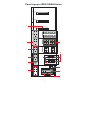
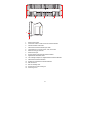
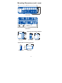
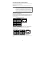
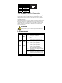
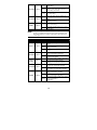
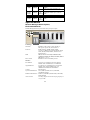
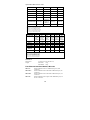
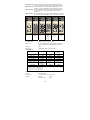
Moxa EtherDevice Switch
EDS-728/828 Hardware Installation Guide
First Edition, January 2008
Moxa Inc.
Tel: +886-2-8919-1230
Fax: +886-2-8919-1231
www.moxa.com
Moxa Technical support.
Worldwide:
[email protected]
The Americas: [email protected]
P/N: 1802008280010
1
V1-
V1+
V2-
V2+
I1
I2
RELAY1
RELAY2
PWR1
PWR2
DI1
DI2
RS-232
Console
T.RING
1
2
P1
P2
1M-2 GTX
MODE
2
V1 V2 INPUT: 24VDC
COUPLER
1
MASTER
FAULT
1
2
P1
P2
LNK/ACT
FDX/HDX
COUPLER
PORT
SPEED
RING
PORT
3
PWR2
9
1M-2 GSFP
PWR
4
2
3
1
IM-4TX
P1
P3
4
PWR1
P2
P4
PWR
1
3
IM-4MSC
TX
RX
IM-4MST
1
2
TX
P1
P3
RX
3
PWR
4
P2
P4
RX
TX
RX
TX
P1
P3
8
STAT
2
4
P2
P4
Panel Layout of EDS-728/828 Series
12
11
10
7
6
5
15
13
14
13
15
16
13
1.
System status LEDs
2.
Push-button switch to select mode for Interface Module
3.
Interface Module mode LEDs
4.
Fast Ethernet Interface Module port LEDs
5.
Terminal block for 2 power inputs, 2 DIs, and 2 DOs
6.
Sticker showing pin contacts
7.
Serial console port
8.
Screw to attach Fast Ethernet Interface Module
9.
Gigabit Ethernet Module LEDs
10. Two cartridge receptors for Gigabit Ethernet Interface Modules
11. Fast Ethernet Interface Modules
12. Sockets for Fast Ethernet Interface Modules
13. DIN-Rail braces
14. Ribs for radiating heat
15. Screw holes for wall mounting kit
16. Grounding screw
2
Mounting Dimensions (unit = mm)
85.00
EtherDevice Switch
EDS-728/828
142.47
30
381.70
Front View
80.6
201.2
362.40
401.00
Rear View
127.8
140.00
142.47
Side View
Front View
Gigabit Ethernet Interface Modules
101.1
24
65.9
Front View
Side View
3
127.8
Fast Ethernet Interface Modules
40
100
128.00
Side View
DIN-Rail Mounting
The DIN-Rail attachment plates are permanently fixed to the back panel of the
EDS-728/828. Do not attempt to remove the attachment plates, since doing so
could damage the product.
To Install:
Lock the brace by pressing the clips and then insert the top of the DIN-Rail
into the notches at the bottom of the top array of heat radiating ribs. Press the
EDS until the brace snaps into place.
To Release:
Use a flat-blade screw driver as a lever to force the braces downwards, and
then pull the EDS-728/828 out away from the DIN-Rail.
Wall Mounting (optional)
For some applications, you will find it convenient to mount the EDS-728/828
on the wall, as illustrated below.
STEP 1: Remove the aluminum DIN-Rail attachment plate from the
EDS-728/828’s rear panel, and then attach the wall mounting plates, as shown
in the diagram.
4
STEP 2:
Mounting the EDS-728/828 on the wall requires 4 screws to
6.0 mm
ensure that the switch does not come loose from the wall.
Use the switch, with wall mounting plates attached, as a
guide to mark the correct locations of the 4 screws. The
heads of the screws should be less than 6.0 mm in diameter, 3.5 mm
and the shafts should be less than 3.5 mm in diameter, as
shown in the figure at the right.
NOTE
Before tightening the screws into the wall, make sure the screw
head and shank size are suitable by inserting the screw into one of
the keyhole-shaped apertures of the Wall Mounting Plates.
Do not screw the screws in all the way—leave about 2 mm to allow room for
sliding the wall mount panel between the wall and the screws.
STEP 3: Once the screws are fixed in the wall, insert the four screw heads
through the large parts of the keyhole-shaped apertures, and then slide Moxa
EDS downwards, as indicated. Tighten the four screws for added stability.
EtherDevice Switch
EDS-728/828
EtherDevice Switch
EDS-728/828
Uninstalling IM-2G Modules
As shown in the figure below, use a flat-blade screw driver as a lever, and pull
or push it to force the IM-2G module outwards. Then pull the module out away
from the EDS-728/828.
5
Wiring Requirements
WARNING
Safety First!
Be sure to disconnect the power cord before installing and/or
wiring your Moxa EDS-728/828.
Calculate the maximum possible current in each power wire and
common wire. Observe all electrical codes dictating the
maximum current allowable for each wire size.
If the current goes above the maximum ratings, the wiring could
overheat, causing serious damage to your equipment.
You should also pay attention to the following guidelines:
y Use separate paths to route wiring for power and devices. If power wiring
and device wiring paths must cross, make sure the wires are perpendicular
at the intersection point.
y NOTE: Do not run signal or communications wiring and power wiring in
the same wire conduit. To avoid interference, wires with different signal
characteristics should be routed separately.
y You can use the type of signal transmitted through a wire to determine
which wires should be kept separate. The rule of thumb is that wiring that
shares similar electrical characteristics can be bundled together.
y Keep input wiring and output wiring separated.
y It is strongly advised that you label wiring to all devices in the system when
necessary.
Grounding Moxa EtherDevice Switch
Grounding and wire routing help limit the effects of noise due to
electromagnetic interference (EMI). Run the ground connection from the
ground screw, on the side panel of the EDS-728/828, to the grounding surface
prior to connecting devices.
ATTENTION
This product is intended to be mounted to a well-grounded
mounting surface, such as a metal panel.
Wiring the Relay Contact
In this section, we explain the meaning of the two contacts used to connect the
alarm contact.
The EDS-728/828 has two sets of relay output—relay 1 and relay 2. Each relay
contact consists of the two contacts of the terminal block on the
EDS-728/828’s top panel. Refer to the next section for detailed instructions on
how to connect the wires to the terminal block connector, and how to attach the
terminal block connector to the terminal block receptor.
6
Top View
RELAY1 RELAY2
V1- V1+
V2- V2+
PWR1
PWR2
I1
DI1
I2
DI2
Front View
FAULT: The two sets of relay
contacts of the 6-pin terminal block
connector are used to detect
user-configured events. The two
wires attached to the Fault contacts
form an open circuit when a
user-configured event is triggered.
If a user-configured event does not
occur, the Fault circuit will be
closed.
Wiring the Redundant Power Inputs
The EDS-728/828 has two sets of power input—power input 1 and power input
2. The top two contacts and the bottom two contacts of the 6-pin terminal block
connector on EDS’s top panel are used for EDS’s two digital inputs.
Top View
V1- V1+
RELAY1 RELAY2
PWR1
V2- V2+
PWR2
I1
DI1
I2
DI2
Front View
STEP 1: Insert the
negative/positive DC wires into the
V-/V+ terminals.
STEP 2: To keep the DC wires
from pulling loose, use a small
flat-blade screwdriver to tighten
the wire-clamp screws on the front
of the terminal block connector.
STEP 3: Insert the plastic terminal
block connector prongs into the
terminal block receptor, which is
located on the EDS-728/828’s top
panel.
Wiring the Digital Inputs
The EDS-728/828 has two sets of digital input—DI 1 and DI 2. Each DI
comprises two contacts of the 6-pin terminal block connector on EDS’s top
panel. The terminal block is also used for EDS’s two DC inputs. Top and front
views of one of the terminal block connectors are shown here.
Top View
RELAY1 RELAY2
V1- V1+
V2- V2+
PWR1
PWR2
I1
DI1
I2
DI2
Front View
STEP 1: Insert the negative
(ground)/ positive DI wires into the
┴/I1 terminals.
STEP 2: To keep the DI wires
from pulling loose, use a small
flat-blade screwdriver to tighten
the wire-clamp screws on the front
of the terminal block connector.
STEP 3: Insert the plastic terminal
block connector prongs into the
terminal block receptor, which is
located on the EDS-728/828’s top
panel.
7
Communication Connections
The pinout and cable wiring diagrams in this section show how the ports on the
EDS-728/828 connect to other devices:
Pinouts are diagrams that indicate the type of signal passing through each of
the port’s pins.
NOTE 1. The pin numbers for male DB9 and DB25 connectors, and hole
numbers for female DB9 and DB25 connectors are labeled on the
connector. However, the numbers are typically quite small, so you
may need to use a magnifying glass to see the numbers clearly.
2. The pin numbers for both 8-pin and 10-pin RJ45 connectors (and
ports) are typically not labeled on the connector (or port). Refer to
the Pinout diagram below to see how RJ45 pins are numbered.
RS-232 Connection
The EDS-728/828 has one RS-232 (10-pin RJ45) console port, located on the
front panel. Use either an RJ45-to-DB9 or RJ45-to-DB25 cable to connect the
Moxa EDS-728/828’s console port to your PC’s COM port. You may then use
a console terminal program to access the Moxa EDS-728/828’s console
configuration utility.
10-Pin
1
2
3
4
5
6
7
8
9
10
10-pin RJ45 Console Pinouts
Description
-----DSR
1
-----GND
TxD
RxD
GND
-----DTR
------
10
10/100BaseT(X) Ethernet Port Connection
Below we show pinouts for both MDI (NIC-type) ports and MDI-X
(HUB/Switch-type) ports.
MDI Port Pinouts
Pin
1
2
3
6
Signal
Tx+
TxRx+
Rx-
MDI-X Port Pinouts
Pin
1
2
3
6
Signal
Rx+
RxTx+
Tx-
8-pin RJ45
1
8
1000BaseT Ethernet Port Connection
1000BaseT data is transmitted on differential TRD+/- signal pairs over copper
wires.
8
MDI/MDI-X Port Pinouts
Pin
1
2
3
4
5
6
7
8
Signal
TRD(0)+
TRD(0)TRD(1)+
TRD(2)+
TRD(2)TRD(1)TRD(3)+
TRD(3)-
1
8
100/1000Base Fiber Port Connection
The concept behind the duplex port and cable is quite straightforward. Suppose
you are connecting devices I and II. Contrary to electrical signals, optical
signals do not require a circuit in order to transmit data. Consequently, one of
the optical lines is used to transmit data from device I to device II, and the
other optical line is used to transmit data from device II to device I, for
full-duplex transmission.
All you need to remember is to connect the Tx (transmit) port of device I to the
Rx (receive) port of device II, and the Rx (receive) port of device I to the Tx
(transmit) port of device II. If you make your own cable, we suggest labeling
the two sides of the same line with the same letter (A-to-A and B-to-B or
A1-to-A2 and B1-to-B2).
ATTENTION
This is a Class 1 Laser/LED product. To avoid causing serious
damage to your eyes, do not stare directly into the Laser Beam.
LED Indicators
LED
STAT
PWR1
PWR2
FAULT
Color
State
Description
System LEDs
System has passed self-diagnosis test on
On
boot-up and is ready to run.
GREEN
System
is undergoing the self-diagnosis
Blinking
test.
RED
On
System failed self-diagnosis on boot-up.
Power is being supplied to the main
On
module’s power input PWR1.
AMBER
Power is not being supplied to the main
Off
module’s power input PWR1.
Power is being supplied to the main
On
module’s power input PWR2.
AMBER
Power is not being supplied to the main
Off
module’s power input PWR2.
The corresponding PORT alarm is
On
enabled and a user-configured event has
been triggered.
RED
The corresponding PORT alarm is
enabled and a user-configured event has
Off
not been triggered, or the corresponding
PORT alarm is disabled.
9
On
MASTER
GREEN
This EDS-728/828 has become Ring
Blinking Master of this Turbo Ring after the
Turbo Ring was broken.
Off
COUPLER GREEN
On
Off
T.RING
NOTE
GREEN
This EDS-728/828 is the Master of this
Turbo Ring.
This EDS-728/828 is not the Master of
this Turbo Ring.
When this EDS-728/828 enables the
coupling function to form a back-up
path.
When this EDS-728/828 disables the
coupling function.
Off
This EDS-728/828 does not belong to an
active Turbo Ring.
On
This EDS-728/828 belongs to an active
Turbo Ring.
Use the Mode push-button switch to cycle among the LNK/ACT,
SPEED, FDX/HDX, RING PORT, and COUPLER PORT LEDs.
The status of these five settings is indicated by the LEDs for the
various ports.
LED
Color
State
Description
Mode LEDs
The corresponding module port’s link is
On
active.
LNK/ACT
GREEN
The corresponding module port’s data is
Blinking being transmitted.
Off
FDX/HDX
GREEN
On
Off
RING
PORT
GREEN
On
Off
On
COUPLER GREEN
Off
The corresponding module port’s link is
inactive.
The corresponding module port’s data is
being transmitted at full duplex.
The corresponding module port’s data is
not being transmitted.
The corresponding module’s port is the
ring port of this EDS-728/828.
The corresponding module’s port is not
the ring port of this EDS-728/828.
The corresponding module’s port is the
coupler port of this EDS-728/828.
The corresponding module’s port is not
the coupler port of this EDS-728/828.
The corresponding module port’s data is
being transmitted at 10 Mbps.
The corresponding module port’s data is
On
being transmitted at 100 Mbps.
The corresponding module port’s data is
Blinking being transmitted at
1000 Mbps.
Off
SPEED
GREEN
10
PWR
P1/P2/
P3/P4
P1/P2
Fast Ethernet Module LEDs
Power is being supplied to the interface
On
module.
GREEN
Power
is not being supplied to the
Off
interface module.
On/
Displays the module port’s status by
GREEN
Off/
mode.
Blinking
Gigabit Ethernet Module LED
On/
Displays the module port’s status by
GREEN
Off/
mode.
Blinking
Specifications
Modular Managed Switch System,
EDS-72810G/82810G
Modular Managed Switch System with 6 slots, and up to 28 ports.
Technology
Standards
Protocols
MIB
Flow Control
Interface
Fast Ethernet
Gigabit Ethernet
Console
System LED Indicators
Module LED Indicators
Alarm Contact
IEEE802.3, 802.3u, 802.3x, 802.1D, 802.1w,
802.1Q, 802.1p, 802.1X, 802.3ad, 802.3z
IGMP Snooping, GMRP, GVRP, SNMP
V1/V2C/V3, DHCP Server/Client, BOOTP, TFTP,
SNTP, SMTP, RARP, RMON, and RIP V1/V2
(EDS-828 only)
MIB-II, Ethernet-Like MIB, P-BRIDGE MIB,
Q-BRIDGE MIB, Bridge MIB, RSTP MIB, RMON
MIB Groups 1, 2.3, 9
IEEE802.3x flow control/back pressure
6 slots for any combination of 4-port Interface
Modules with 10/100BaseT(X) or 100BaseFX
2 sockets for any combination of 2-port Interface
Modules with 10/100/1000BaseT(X), and
1000BaseSX/LX/LHX/ZX SFP modules
RS-232 (RJ45)
STAT, PWR1, PWR2, FAULT, MASTER,
COUPLER, T.RING
LNK/ACT, FDX/HDX, RING PORT, COUPLER,
PORT, SPEED
Two relay outputs with current carrying capacity of
1A @ 24 VDC
11
Two inputs with the same ground, but electrically
isolated from the electronics.
x For state “1”: +13 to +30V
x For state “0”: -30 to +3V
x Max. input current: 8 mA
Digital Inputs
Power
Input Voltage
Connection
Power Consumption
Overload Current
Protection
Reverse Polarity
Protection
Mechanical
Casing
Dimensions
Weight
Installation
24 VDC (12 to 45 VDC), redundant dual inputs
Two removable 6-pin terminal blocks
EDS-72810G/82810G
22.9W
IM-4TX
2.5W
IM-2MSC/2TX
5W
IM-2MST/2TX
5W
IM-2SSC/2TX
5W
IM-4MSC
7.2W
IM-4MST
7.2W
IM-4SSC
7.2W
IM-1LSC/3TX
4W
IM-2GTX
3W
IM-2GSFP
3W
Present
Present
IP30 protection
362 x 146 x 128 mm (W x H x D)
1850g
DIN-Rail, Wall Mounting (optional kit)
Gigabit Ethernet Interface Module, IM-2G Series
IM-2GTX:
IM-2GSFP:
Interface Module with 2 10/100/1000BaseT(X) ports, RJ45
connectors.
Interface Module with 2 1000BaseSX/LX/LHX/ZX SFP
sockets for SFP modules.
P2
P1
P2
P1
2
2
1
1
1M-2 GSFP
1M-2 GTX
IM-2GTX
Interface
LED Indicators
RJ45 Ports
Distance
Fiber Ports
IM-2GSFP
P1, P2 for Port Status
10/100/1000BaseT(X) auto negotiation speed, and
auto MDI/MDI-X connection
100 m
1000BaseSX/LX/LHX/ZX (SFP socket)
12
Optical Fiber/SFP-1GxxxLC Series
SX
LX
LHX
ZX
Wavelength
850 nm
1310 nm
1310 nm
1310 nm
Max. Tx
-4 dBm
-3 dBm
1 dBm
+5 dBm
Min. Tx
-9.5 dBm
-9.5 dBm
-4 dBm
0 dBm
Rx Sensitivity
-18 dBm
-20 dBm
-24 dBm
-24 dBm
Link Budget
8.5 dB
10.5 dB
20 dB
24 dB
Typical Distance
550m (a)
275m (b)
1100m (c)
550m (d)
10km (e)
40km (e)
80km (f)
Saturation
0 dBm
-3 dBm
-3 dBm
-3 dBm
a. [50/125 μm, 400 MHz*km] cable
b. [62.5/125 μm, 200 MHz*km] cable
c. [50/125 μm, 800 MHz*km] cable
d. [62.5/125 μm, 500 MHz*km] cable
e. [9/125 μm, 3.5 PS/(nm*km)] cable
f. [9/125 μm, 19 PS/(nm*km)] cable
10A
10B
20A
20B
40A
TX:
TX:
TX:
TX:
TX:
1310nm 1550nm 1310nm 1550nm 1310nm
RX:
RX:
RX:
RX:
RX:
1550nm 1310nm 1550nm 1310nm 1550nm
-3 dBm -3 dBm -2 dBm -2 dBm +2 dBm
Max. Tx
-9 dBm -9 dBm -8 dBm -8 dBm -3 dBm
Min. Tx
Rx Sensitivity -21 dBm -21 dBm -23 dBm -23 dBm -23 dBm
12 dB
12 dB
15 dB
15 dB
20 dB
Link Budget
10 km
10 km
20 km
20 km
40 km
Typical
Distance
-1 dBm -1 dBm -1 dBm -1 dBm -1 dBm
Saturation
Wavelength
40B
TX:
1550nm
RX:
1310nm
+2 dBm
-3 dBm
-23 dBm
20 dB
40 km
-1 dBm
a. [50/125 μm, 400 MHz*km] cable
b. [62.5/125 μm, 200 MHz*km] cable
c. [50/125 μm, 800 MHz*km] cable
d. [62.5/125 μm, 500 MHz*km] cable
e. [9/125 μm, 3.5 PS/(nm*km)] cable
f. [9/125 μm, 19 PS/(nm*km)] cable
Mechanical
Dimensions
Weight
24 x 66 x 101 mm (W x H x D)
IM-2GTX
150g
IM-2GSFP
148g
Fast Ethernet Interface Module, IM series
IM-4TX:
IM-4MSC:
IM-4MST:
IM-4SSC:
Interface Module with 4 10/100BaseT(X) ports, RJ45
connectors.
Interface Module with 4 multi mode 100BaseFX ports, SC
connectors.
Interface Module with 4 multi mode 100BaseFX ports, ST
connectors.
Interface Module with 4 single mode 100BaseFX ports, 40
km SC connectors.
13
IM-2MSC/2TX: Interface Module with 2 multi mode 100BaseFX ports, SC
connectors, and 2 10/100BaseT(X) ports, RJ45 connectors.
IM-2MST/2TX: Interface Module with 2 multi mode 100BaseFX ports, ST
connectors, and 2 10/100BaseT(X) ports, RJ45 connectors.
IM-2SSC/2TX: Interface Module with 2 single mode 100BaseFX ports, 40
km SC connectors, and 2 10/100BaseT(X) ports, RJ45
connectors.
IM-1LSC/3TX: Interface Module with 1 single mode 100BaseFX port, 80 km
SC connector and 3 10/100BaseT(X) ports, RJ45 connectors.
P3
P4
P1
P2
PWR
P3
P4
P1
P2
PWR
3
3
1
P3
P4
P1
P2
PWR
4
P3
P4
P1
P2
PWR
3
4
P3
P4
P1
P2
PWR
3
4
P3
P4
P1
P2
PWR
3
4
4
4
3
TX
TX
TX
TX
RX
RX
RX
RX
1
2
IM-4TX
IM-4TX
2
1
2
TX
TX
RX
RX
IM-4MSC
IM-4MST
1
IM-2MSC/2TX
IM-4MSC, IM-4MST
IM-4SSC,
Interface
LED Indicators
RJ45 Ports
Distance
Fiber Ports
Optical Fiber
Wavelength
Max. Tx
Min. Tx
Rx Sensitivity
Link Budget
Typical Distance
Saturation
1
2
RX
2
1
IM-2MST/2TX
2
IM-1LSC/3TX
IM-2MSC/ IM-2MST/
2TX
2TX
IM-2SSC/
2TX
IM-1LSC/
3TX
PWR, P1, P2, P3, P4 port status
10/100/1000BaseT(X) auto negotiation speed, F/H
duplex mode, and auto MDI/MDI-X connection
100 m
100BaseFX ports (SC/ST connector)
Multi-mode
Single-mode
1300 nm
-10 dBm
-20 dBm
-32 dBm
12 dB
5 km (a)
4 km (b)
-6 dBm
1310 nm
0 dBm
-5 dBm
-34 dBm
29 dB
40 km (c)
Single-mode,
80 km
1550 nm
0 dBm
-5 dBm
-34 dBm
29 dB
80 km (d)
-3 dBm
-3 dBm
a. using [50/125 μm, 800 MHz*km] cable
b. using [62.5/125 μm, 500 MHz*km] cable
c. using [9/125 μm, 3.5 PS/(nm*km)] cable
d. using [9/125 μm, 19 PS/(nm*km)] cable
Mechanical
Casing
Dimensions
Weight
TX
IP30 protection
40 x 130 x 100 mm (W x H x D)
IM-4TX
215 g
IM-2MSC/2TX
245 g
14
IM-2MST/2TX
IM-2SSC/2TX
IM-1LSC/3TX
IM-4MSC
IM-4MST
IM-4SSC
Environmental
Operating Temperature
Storage Temperature
Ambient Relative
Humidity
Regulatory Approvals
Safety
Hazardous Location
EMI
EMS
Shock
Freefall
Vibration
WARRANTY
250 g
245 g
235 g
250 g
270 g
270 g
0 to 60°C (32 to 140°F)
-40 to 85°C (-40 to 185°F)
5 to 95% (non-condensing)
UL60950-1, CSA C22.2 No. 60950-1,
EN60950-1 (Pending), UL508 (Pending)
UL/cUL Class I, Division 2, Groups A, B, C and D
(Pending)
ATEX Class I, Zone 2, EEx nC IIC (Pending)
FCC Part 15, CISPR (EN55022) class A
EN61000-4-2 (ESD), Level 3
EN61000-4-3 (RS), Level 3
EN61000-4-4 (EFT), Level 4
EN61000-4-5 (Surge), DC Input: level 4; Comm.
Line: level 3
EN61000-4-6 (CS), Level 3
EN61000-4-8
EN61000-4-11
EN61000-4-12
IEC60068-2-27
IEC60068-2-32
IEC60068-2-6
5 years
Moxa Internet Services
Customer satisfaction is our number one concern, and to ensure that customers
receive the full benefit of our products, Moxa has set up on-line support
services to provide technical support, driver updates, product information, and
user’s manual updates.
E-mail for technical support:
[email protected] (Worldwide)
[email protected] (The Americas)
15
Website for up to date product
information: www.moxa.com