1
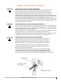
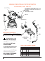
Manual ID: Drive Manual RV Series.indd
Release Date: June, 20 2014
Owner’s Manual
Parts Manual
Safety Precautions
Operating Instructions
Maintenance
Printed in the USA
VARIABLE SPEED MODELS:
dV-20 DV-30 DV-40
IMPORTANT!
Variable speed motor MUST NOT BE
OPERATED without being pre-filled with
hydraulic fluid. Operating the motor
without hydraulic fluid WILL CAUSE
EXTENSIVE DAMAGE.
The motor has been equipped with quick
connect couplers to ensure the motor
has fluid at all times. The motor is filled
with hydraulic fluid at the factory and is
shipped in a ready to use condition.
All DV series units require the use of a
motor case drain line. THE DRAIN LINE
MUST BE USED TO AVOID DAMAGE
TO THE HYDRAULIC MOTOR.
800-599-0211 l www.pengoattachments.com l PENGO: 500 East Highway 10, Laurens, IA 50554, USA
Variable Speed DV Series Manual
1
PREFACE
This manual is used to familiarize you with safety, assembly, operation, adjustment, troubleshooting, and maintenance.
Read and follow the recommendations in this manual to ensure safe and efficient operation. Keep this manual with the
attachment at all times for future reference.
We want you to be completely satisfied with your new product, feel free to contact your local Authorized Service Dealer for
help with service, replacement parts, or any other information you may require. If you need assistance in locating a dealer,
visit our web site at www.pengoattachments.com or call customer service at 1-800-599-0211.
Whenever you contact your Authorized Service Dealer or PENGO, always have the model number and serial number of
your product available. These numbers will help provide exact information about your specific product. You will find the
model and serial numbers on an ID plate located on the product.
The descriptions and specifications in this manual are subject to change without notice. PENGO reserves the right to improve
products. Some product improvements may have taken place after this manual was printed. For the latest information on
PENGO attachments, visit our web site at www.pengoattachments.com or call customer service at 1-800-599-0211.
Thank you for buying and using PENGO attachments!
TABLE OF CONTENTS
Preface / Table of Contents ................................................................................................................................. 2
Safety Statements ............................................................................................................................................ 3
General Precautions ........................................................................................................................................... 4
General Precautions Cont. .................................................................................................................................. 5
General Precautions Cont. (811 Information) / Serial Number Identification ....................................................... 6
Product / Equipment Precautions ........................................................................................................................ 7
Safety Decal Information ..................................................................................................................................... 8
Product Specifications DV-20 / DV-30 ................................................................................................................ 9
Product Specifications DV-40 ............................................................................................................................ 10
Typical Attachment Connections .......................................................................................................................11
Set-Up / Hydraulic System Hook-Up / Operating Procedures ............................................................................ 12
Operating Procedures Cont. / Maintenance Instructions ................................................................................... 13
Maintenance Instructions / Storage Instructions ................................................................................................ 14
Maintenance Instructions / Storage Instructions / Checking and Changing Gear Oil ........................................ 15
Troubleshooting
........................................................................................................................................... 16
Hydraulic Motor Quick Coupler Information ....................................................................................................... 17
Variable Speed Hydraulic Motor Information DV-20 .......................................................................................... 18
Variable Speed Hydraulic Motor Information DV-30 / DV-40 ............................................................................. 19
Parts Breakdown DV-20 .................................................................................................................................... 20
Gearbox Breakdown DV-20 ............................................................................................................................... 21
Parts Breakdown DV-30 .................................................................................................................................... 22
Gearbox Breakdown DV-30 ............................................................................................................................... 23
Parts Breakdown DV-40 .................................................................................................................................... 24
Gearbox Breakdown DV-40 ............................................................................................................................... 25
Pengo Warranty Policy ....................................................................................................................................... 26
Torque Chart for Common Bolts ........................................................................................................................ 27
2
Variable Speed DV Series Manual
SAFETY STATEMENTS
DANGER
THIS STATEMENT IS USED WHERE SERIOUS INJURY OR DEATH WILL RESULT IF THE
INSTRUCTIONS ARE NOT FOLLOWED PROPERLY.
WARNING
THIS STATEMENT IS USED WHERE SERIOUS INJURY OR DEATH COULD RESULT IF
THE INSTRUCTIONS ARE NOT FOLLOWED PROPERLY.
CAUTION
THIS STATEMENT IS USED WHERE MINOR INJURY COULD RESULT IF THE
INSTRUCTIONS ARE NOT FOLLOWED PROPERLY.
THIS SYMBOL BY ITSELF OR USED WITH A SAFETY SIGNAL WORD THROUGHOUT
THIS MANUAL IS USED TO CALL YOUR ATTENTION TO INSTRUCTIONS INVOLVING
YOUR PERSONAL SAFETY OR THE SAFETY OF OTHERS. FAILURE TO FOLLOW
THESE INSTRUCTIONS CAN RESULT IN INJURY OR DEATH.
WARNING
READ MANUAL PRIOR TO INSTALL
Improper installation, operation, or maintenance of the equipment could result in serious
injury or death. Operators and maintenance personnel should read this manual as well as
all manuals related to this equipment. FOLLOW ALL SAFETY INSTRUCTIONS IN THIS
MANUAL.
WARNING
READ AND UNDERSTAND ALL SAFETY STATEMENTS
Read all safety decals and safety statements in all manuals prior to operating or working
on this equipment. Know and obey all OSHA regulations, local laws and other professional
guidelines for your operation. Know and follow good work practices when assembling,
maintaining, repairing, mounting, removing or operating this equipment.
KNOW YOUR EQUIPMENT
Know your equipment’s capabilities, dimensions and operations before operating. Visually
inspect your equipment before you start, and never operate equipment that is not in proper
working order with all safety devices intact. Check all hardware to assure it is tight. Make
certain that all locking pins, latches, and connection devices are properly installed and
secured. Remove and replace any damaged, fatigued or excessively worn parts. Make
certain all safety decals are in place and are legible. Keep decals clean, and replace them if
they become worn and hard to read.
WARNING
DO NOT MODIFY EQUIPMENT
Modifications may weaken the integrity of the equipment and may impair the functions, safety,
life, and performance of the equipment. When making repairs, use only the manufactures
genuine parts, following authorized instructions. Other parts may be substandard in fit and
quality.
PREPARE FOR EMERGENCIES
• Be prepared if a fire starts.
• Keep a first aid kit near by when operating equipment.
Variable Speed DV Series Manual
3
GENERAL PRECAUTIONS
WARNING
OPERATOR SAFETY
• Protective clothing and equipment should be worn at all times.
• Wear protective clothing and equipment appropriate for the job. Avoid loose fitting clothing.
• Prolonged exposure to excessive noise can cause hearing loss. Wear suitable hearing protection
such as ear plugs.
• Operating equipment safely requires the full attention of the operator. Avoid distractions.
• Do not operate the unit when you are tired, ill or under the influence of alcohol, drugs or
medication.
• Never let a minor or inexperienced person operate the unit.
• Keep all body parts away from the drilling bit at all times.
• Inspect the area to be drilled before operation. Remove objects which can be thrown or become
entangled.
• DO NOT operate the Drive attachment in areas where carbon monoxide fumes can accumulate.
CAUTION
PRODUCT SAFETY
• Inspect the entire product before operation.
• Replace parts that are cracked, chipped or damaged in any way before operation.
• Keep others away when making any adjustments to the unit.
• Damage to the Auger Drive and auger bit can result if the prime mover moves while the auger is
still in the hole.
WARNING
PRACTICE SAFE MAINTENANCE
•
•
•
•
•
WARNING
Use proper tools and equipment when conducting maintenance.
Work in a clean dry area.
Inspect all parts. Be sure parts are in good working condition and installed properly.
Remove build up of grease, oil or any debris.
Remove all tools and unused parts from equipment before beginning operation.
BE ALERT ON THE JOB SITE
Tragic accidents can occur if the operator is not alert to the presence of bystanders. Children in
particular are often attracted to machinery and work activity. Never assume that children will remain
where you last saw them. BE ALERT and turn the equipment off if children enter the work area. Keep
children out of the work area and under supervision of another responsible adult.
WARNING
DRILLING SAFETY
• Inspect the area to be drilled before operation. Remove objects which can be thrown or become
entangled. Be alert when drilling in locations where any type of landscaping fabric / mat may be
present. The material can be rapidly drawn into the point of operation, possibly causing injury or
death to anyone standing on or near the fabric.
• Keep all parts of your body away from the drilling bit when operating the unit.
• DO NOT operate the Auger Drive when the auger bit is more then 12” (305mm) above ground. The
auger bit may bind and cause injury to the operator and damage to the equipment.
• While the auger bit is rotating, DO NOT attempt to manually guide the auger to a location.
• Ensure that overhead power / utility lines do not come into contact with the Drive attachment.
• DO NOT use a shovel or any other object to remove material from the auger bit or the hole while
the Drive attachment is in use.
WARNING
UNDERGROUND HAZARDS
It is the responsibility of the operator to know where buried power, gas, telephone, and other utilities
are at in the work area. This may lead to shock or an explosion. Have the work area marked for buried
lines and do not dig in marked areas set by your local municipals. Striking a hard object underground
with the auger turning can result in the slowing or stopping of the auger.
4
Variable Speed DV Series Manual
GENERAL PRECAUTIONS - CONTINUED
WARNING
LOWER OR SUPPORT RAISED EQUIPMENT
Do not work under raised booms without supporting them. Do not use support material
made of concrete blocks, logs, buckets, barrels, or any other material that could
suddenly collapse or shift positions. Make sure support material is solid, not decayed,
warped, twisted, or tapered. Lower booms to ground level or on blocks. Lower booms
and attachments to the ground before leaving the cab or operator’s station. Whenever the boom
structure must be raised for attachment installation or servicing block ensure the boom locking
devices (if equipped) are deployed to prevent the accidental lowering of boom structures.
NEVER PLACE ANY BODY PART BETWEEN THE PRIME MOVER CHASSIS AND THE BOOM
STRUCTURE! Refer to the operating and maintenance instructions provided by the prime mover
manufacturer for specific information.
WARNING
USE CARE WITH SILICA DUST DURING OPERATION
Concrete and masonry products contain silica sand. Quartz, which is a form of silica and the most
common mineral in the earths crust, is associated with many types of rock. Some activities that
silica dust may be present in the air include demolition, sweeping, loading, sawing, hammering,
drilling, or planing of rock, concrete or masonry.
It is recommended to use dust suppression, dust collection or personal protective equipment
during the operation of any attachment that may cause high levels of silica dust.
The NIOSH recommended exposure limit for respirable crystalline silica is 0.05 mg/m3 as a timeweighted average for up to 10 hours/day during a 40-hour workweek [NIOSH 1974].
WARNING
USE CARE WITH HYDRAULIC FLUID PRESSURE
Hydraulic fluid under pressure can penetrate the skin and cause serious injury or
death. Hydraulic leaks under pressure may not be visible. Before connecting or
disconnecting hydraulic hoses, read your prime mover’s operator’s manual for
detailed instructions on connecting and disconnecting hydraulic hoses or fittings.
• Keep unprotected body parts, such as face, eyes, and arms as far away as
possible from a suspected leak. Flesh injected with hydraulic fluid may develop
gangrene or other permanent disabilities.
• If injured by injected fluid, see a doctor at once. If your doctor is not familiar with
this type of injury, ask him to research it immediately to determine proper treatment.
• Wear safety glasses, protective clothing, and use a piece of cardboard or wood
when searching for hydraulic leaks. DO NOT USE YOUR HANDS! SEE ILLUSTRATION.
Variable Speed DV Series Manual
5
GENERAL PRECAUTIONS - CONTINUED
One easy phone call to 811 starts the process to get your underground utility lines marked for free. When you call
811 from anywhere in the country (USA), your call will be routed to your local One Call Center. Local One Call Center
operators will ask you for the location of your digging job and route your call to affected utility companies. Your utility
companies will then send a professional locator to your location to mark your lines within a few days. Once your
underground lines have been marked, you will know the approximate location of your utility lines and can dig safely,
because knowing what’s below protects you and your family.
Every state has different rules and regulations governing digging, some stricter than others. In addition, 62 separate
One Call Centers serve different areas of the country; now 811 will connect you directly to your local one call center.
For more information go to www.call811.com
Always call 811 before starting any digging project!
**Customers outside the United States need to contact their local utility company for underground safety regulations
specific to the area.
SERIAL NUMBER IDENTIFICATION
Its important to make the correct reference to the serial number of the unit when making repairs
or ordering parts. The serial number plate will be located near the top of the Anchor / Auger Drive
attachment. Below is an example of the serial number plate.
Figure 1
6
Variable Speed DV Series Manual
PRODUCT / EQUIPMENT PRECAUTIONS
CAUTION
PRIME MOVER LIFT CAPACITY
Alert yourself to the weight of the Drive Unit. DO NOT exceed the recommended lift capacity of
the prime mover. Refer to your prime mover’s owners manual for suggested lift capacity and lift
considerations.
WARNING
PRIME MOVER / ATTACHMENT INSTALLATION
Ensure all connection pins, fasteners and latches are properly secured. Ensure that the mounting
frame / attachment mounting plate is rigidly secured to the prime mover. Improper installation
can result in product damage, personal injury and death.
Ensure all hydraulic hose assemblies are of adequate length and have enough slack for full Drive
attachment movement. Failure to provide adequate length hydraulic hoses can result in hose
rupturing. A hydraulic hose rupture can result in product damage, personal injury and death.
OPERATING THE PRIME MOVER
Avoid steep hillside operation, which could cause the prime mover to overturn. Consult
your prime mover operator’s and safety manuals for maximum incline allowable.
WARNING
TRANSPORTING THE DRIVE ATTACHMENT
• Travel only with the Drive attachment in a safe transport position to prevent uncontrolled
swinging.
• Tether the Drive attachment with a chain, if necessary, to prevent uncontrolled swinging of the auger
when moving from hole to hole.
• Remove the earth auger or helical anchor from the Drive attachment before transporting to and
from the job site.
• Use extreme care during transport to prevent contact between the Drive attachment and bystanders
or solid objects. Contact with the Drive attachment could cause serious damage, injury or death.
• Never operate the Drive attachment while transporting.
• Drive slowly over rough ground and on slopes. Position the Drive attachment as low to the ground
as possible maintaining a low center of gravity.
CAUTION
DRIVE ATTACHMENT SIDE LOADING
Side loading is NOT recommended. Excessive side loading can cause output shaft deflection and or
failure. Avoid excessive side loading to prevent possible instantaneous output shaft failure. Such a
failure could result in injury from disconnected parts and or being hit by the Drive attachment causing
serious injury or death.
Variable Speed DV Series Manual
7
SAFETY DECAL INFORMATION
SAFETY DECALS
This unit comes equipped with all safety decals in place. They are designed to help you safely operate
your unit. Read and follow all safety decals.
• Keep all safety decals clean and legible at all times.
• Replace safety decals that are missing or have become illegible.
• Safety decals are available from your distributor or manufacture.
• Some parts installed during repair may require safety decals to be affixed to the replacement part.
When ordering the replacement part(s) be sure the correct safety decal(s) are included in your order.
INSTALLING SAFETY DECALS
•
•
•
•
Clean the desired area with warm soapy water.
Decide on exact position before you remove the backing paper.
Peel backing paper from decal. Press firmly on the surface.
Air pockets can be pierced with a pin and smoothed.
Typical Decal used on Pengo Auger Drive Attachments
350247
Figure 2
8
Variable Speed DV Series Manual
PRODUCT SPECIFICATIONS
AUGER DRIVE MODEL
dv-20
AUGER DRIVE MODEL
dv-30
TOTAL UNIT WEIGHT
880 LBS / 400 Kg
HYDRAULIC MOTOR INFORMATION
8.25 cu/in (135cc)
Displacement
Variable Speed Bi-Directional
Motor Type
8/16 Spline 13T
Motor Output Shaft
SAE - D 2 Bolt
Motor Mount
Radial (Quick Coupler)
Motor Ports
Cross Over Pressure Relief None
PLANETARY GEARBOX INFORMATION
Gearbox Type
Planetary Three Stage
Reduction Ratio
60.56:1
Output Shaft
3” Hex
Oil Capacity
3.0 Gallons
Oil Type
SAE 80W90 GL-5
Shaft Pull Out (lbs.)
45,000 lbs.
REFERENCE TORQUE CHART
TOTAL UNIT WEIGHT
1250 LBS / 566 Kg
HYDRAULIC MOTOR INFORMATION
10.06 cu/in (165cc)
Displacement
Variable Speed Bi-Directional
Motor Type
8/16 Spline 13T
Motor Output Shaft
SAE - D 2 Bolt
Motor Mount
Radial (Quick Coupler)
Motor Ports
Cross Over Pressure Relief None
PLANETARY GEARBOX INFORMATION
Gearbox Type
Planetary Three Stage
Reduction Ratio
69.7:1
Output Shaft
4” Square
Oil Capacity
3.17 Gallons
Oil Type
SAE 80W90 GL-5
Shaft Pull Out (lbs.)
60,000 lbs.
REFERENCE TORQUE CHART
Pressure PSI (Bar) High Torque (ft/lbs)
Pressure PSI (Bar) High Torque (ft/lbs)
2600
2800
3000
3200
3400
3600
3800
4000
(110)
(124)
(137)
(151)
(165)
(179)
(193)
(206)
Low Torque (ft/lbs)
14629
8669
15755
9336
16880
10003
18006
10670
19131
11336
20256
12004
21382
12671
22507
13337
REFERENCE SPEED CHART
High Spd (rpm)
Flow GPM (Liter) Low Spd (rpm)
40 (150)
16
27
45 (169)
18
30
50 (188)
20
33
55 (206)
22
37
60 (225)
24
40
2600
2800
3000
3200
3400
3600
3800
4000
Low Torque (ft/lbs)
(110)
(124)
(137)
(151)
(165)
(179)
(193)
(206)
20579
8481
22162
9133
23746
9786
25328
10438
26912
11091
28495
11743
30078
12396
31661
13048
REFERENCE SPEED CHART
High Spd (rpm)
Flow GPM (Liter) Low Spd (rpm)
40 (152)
11
27
45 (171)
13
31
50 (190)
14
34
55 (209)
15
37
60 (228)
17
41
Output speed and torque specifications are NOT listed at 100% efficiency. Maximum efficiencies have been applied to the torque
and speed charts according to the manufacturers recommendations. Speed and torque output are dependant on the overall
system efficiencies associated with the prime movers hydraulic system. When the purchaser is determining criteria for specific
applications please contact Pengo. Pengo has made every attempt to present accurate and suitable information published on this
document. This document should be used for information and comparative purposed only. When application specific information is
required, please contact Pengo.
Pengo continually looks for new ways to improve its products. Therefore, Pengo reserves the right to make changes to our
products and specifications without notice.
Variable Speed DV Series Manual
9
PRODUCT SPECIFICATIONS
AUGER DRIVE MODEL
dv-40
TOTAL UNIT WEIGHT
1500 LBS / 680 Kg
HYDRAULIC MOTOR INFORMATION
10.06 cu/in (165cc)
Displacement
Variable Speed Bi-Directional
Motor Type
8/16 Spline 13T
Motor Output Shaft
SAE - D 2 Bolt
Motor Mount
Radial (Quick Coupler)
Motor Ports
Cross Over Pressure Relief None
PLANETARY GEARBOX INFORMATION
Gearbox Type
Planetary Three Stage
Reduction Ratio
83.78:1
Output Shaft
130mm Square
Oil Capacity
4.0 Gallons
Oil Type
SAE 80W90 GL-5
Shaft Pull Out (lbs.)
60,000 lbs.
REFERENCE TORQUE CHART
Pressure PSI (Bar) High Torque (ft/lbs)
2600
2800
3000
3200
3400
3600
3800
4000
Low Torque (ft/lbs)
(110)
(124)
(137)
(151)
(165)
(179)
(193)
(206)
24737
10194
26640
10979
28542
11762
30445
12547
32348
13331
34251
14115
36154
14900
38056
15683
REFERENCE SPEED CHART
High Spd (rpm)
Flow GPM (Liter) Low Spd (rpm)
40 (152)
9
23
45 (171)
10
25
50 (190)
12
28
55 (209)
13
31
60 (228)
14
34
Output speed and torque specifications are NOT listed at 100% efficiency. Maximum efficiencies have been applied to the torque
and speed charts according to the manufacturers recommendations. Speed and torque output are dependant on the overall
system efficiencies associated with the prime movers hydraulic system. When the purchaser is determining criteria for specific
applications please contact Pengo. Pengo has made every attempt to present accurate and suitable information published on this
document. This document should be used for information and comparative purposed only. When application specific information is
required, please contact Pengo.
Pengo continually looks for new ways to improve its products. Therefore, Pengo reserves the right to make changes to our
products and specifications without notice.
10
Variable Speed DV Series Manual
TYPICAL ATTACHMENT CONNECTIONS
IMPORTANT: Before connecting the attachment to prime mover, inspect all mounting surfaces, attachment plates,
and quick couplers are free of dirt and debris. Ensure all attaching pins, fasteners and latches are properly secured.
Ensure that the mounting frame / attachment mounting plate is rigidly secured to the prime mover. Improper
installation can result in product damage, personal injury and death.
1
EXCAVATOR / BACKHOE MOUNT
END OF BOOM (Figure 3)
Mounting Bracket connects directly to the boom with
the customer supplier connection pin. The Drive Unit
connects to the Mounting Bracket with the supplied
connection pin.
2
EXCAVATOR / BACKHOE MOUNT
QUICK COUPLER (Figure 4)
Mounting Bracket connects to the quick coupler when
the jaws of the quick coupler engage the pins on the
Mounting Bracket. The Link Arm connects to both the
Mounting Bracket and the Drive Unit with the supplied
connection pins.
Figure 3
Figure 4
These illustrations represent the two most common attachment connections.
Note the hydraulic hoses are not shown in these illustrations.
Variable Speed DV Series Manual
11
SET-UP INSTRUCTIONS
READ AND UNDERSTAND ALL SAFETY INFORMATION
PRIOR TO MOUNTING YOUR DRIVE UNIT TO THE
PRIME MOVER. SEE PAGES 6 & 12.
3. Ensure that the hydraulic hose couplers are compatible
with the hydraulic quick couplers on the Drive Unit.
WARNING If a hydraulic leak develops, correct it
MOUNTING AND INSTALLATION
There are several ways to mount your Drive Unit
depending on the prime mover and application. See
figures 3 and 4 on page 12.
Backhoe and Excavator Mounting
Remove the bucket from the dipper arm and curl cylinder
pin connections.
AUGER / ANCHOR CONNECTION
1. Align the auger bit or anchor with the output shaft of
the Drive Unit.
2. Slide the connecting coupler (hub) over the output
shaft and align the coupler hole with the output shaft
hole.
3. Connect the auger bit or anchor to the Drive Unit
output shaft and secure it with appropriate connecting
hardware.
WARNING When selecting connecting hardware
ensure that the bolt or pin does not
protrude from the coupler (hub) any more
then necessary to secure. Hardware that
protrudes an excessive amount can be a safety hazard
and cause entanglement.
HYDRAULIC SYSTEM HOOK-UP
Your Pengo Planetary Drive Unit receives its hydraulic
oil flow and pressure from the prime mover through the
auxiliary hydraulic circuit via two quick release couplers
near the end of the truck boom or excavator arm. Follow
the steps below to complete the hydraulic hook-up
between your prime mover and Drive Unit.
HYDRAULIC SYSTEM HOOK-UP
1. Locate the auxiliary hydraulic connection ports on the
prime mover.
2. Determine the length of hydraulic hose necessary to
connect the auxiliary hydraulic circuit to the Drive Unit. Be
sure to allow sufficient “slack” in the hose length to allow
the Drive Unit to perform it’s full range of operation.
12
immediately. Escaping hydraulic fluid can
have extremely high pressure. A stream
of high pressure fluid may penetrate the
skin. It is imperative that the connections are tight and that
all hoses are in good working condition.
4. Once all of the hydraulic connections have been made and
checked for leaks, the Drive Unit is ready for operation.
CAUTION Hydraulic hoses and fittings used on the
prime mover and Drive Unit must have a
continuous operating pressure rating of
at least 25% higher than the maximum
pressure of the hydraulic system being used. Refer to
the Drive Unit specification chart for allowable maximum
pressure.
OPERATING PROCEDURES
Before operating, always ensure that the Drive Unit and
auger or anchor are connected correctly to the prime
mover.
DRILLING / ANCHORING OPERATION
1. To begin drilling/installation, position the auger or anchor
on the ground in the desired location. Engage the parent
machines auxiliary hydraulics to rotate the auger or anchor
in a clockwise direction.
2. Lower the parent machines arm(s) to engage the
auger or anchor into the ground. Use only enough down
pressure to assure positive penetration. Ease up on the
down pressure if the auger or anchor rotation slows down
drastically or stalls. Excessive down pressure will cause
the Drive Unit to stall frequently.
Note: Do not continually stall the Drive Unit! Continued
stalling may cause excessive heating of the hydraulic
system and possible damage to the Drive Unit.
3. As the auger or anchor digs in the ground, the prime
movers arm(s) or boom may travel through an arc. This
means the operator may need to continually reposition
the auger or anchor to ensure vertical application of the
auger or anchor.
Variable Speed DV Series Manual
OPERATING PROCEDURES CONT.
MAINTENANCE INSTRUCTIONS
DRILLING OPERATION ONLY
After steps 1-3 above have been completed continue
with the following steps for drilling applications.
Before operating the Drive Unit ensure it is properly lubricated
and inspected for any worn or damaged areas. Only a
minimum amount of time and effort is required to regularly
lubricate and maintain the Drive Unit. Preventive maintains
will help ensure long life and trouble free operation.
4. When the auger has penetrated the ground about
24” (610mm), raise the auger from the hole to clean out
the loose material.
5. Once the required hole depth is reached, allow the
auger to turn a few seconds at this depth to clean the
hole.
6. Stop rotation of the auger and raise the auger out of
the hole. Swing the auger away from the newly drilled
hole. Spin the lose material off the auger.
Note: Do not reverse the auger rotation while the auger
is still in the hole. The lose material will back fill the
hole.
If necessary, repeat steps 4 through 6 to obtain a cleaner
hole.
OPERATIONS TO AVOID
1. In some soil conditions or when excessive down
pressure is applied, the auger may “screw” itself into
the ground. This can cause the auger to become stuck
causing the Drive Unit to stall. If this situation occurs,
reverse the auger rotation and slowly raise the auger
from the hole.
2. If the auger becomes lodged under rocks, tree roots,
or other large obstructions, do not attempt to raise the
auger out of the ground. See Step 1 of this section to
relieve the auger.
3. Avoid excessive side loading. This can cause damage
to both the Drive Unit and the auger bit.
LUBRICATION MAINTENANCE
The Drive Unit must be properly lubricated to achieve the
most efficient operation. Clean excess grease, gear oil, and
hydraulic fluid for the Drive Unit. This is especially important
in sandy conditions.
HYDRAULIC OIL MAINTENANCE
CLEAN HYDRAULIC OIL IS ESSENTIAL!
80% of all hydraulic component failures are caused by
Contamination of the hydraulic oil. Always keep all dirt and
other contaminates from entering the hydraulic system
during disconnect and connect operations. Always use dust
caps and plugs on all quick disconnects when not in use.
Tightly cap all hydraulic openings to hold oil in and keep dirt
and other contaminates from entering hydraulic systems.
HYDRAULIC HOSE MAINTENANCE
Inspect all hydraulic hoses daily for cracked and brittle
covers caused by excessive heat. Reduced viscosity of
hydraulic oil occurs at higher operating temperatures and
causes a breakdown of fluid additives, such as wear
inhibitors. Excessive heat will cause higher internal leakage
in the Drive Unit motor, which will make the Drive Unit less
efficient. It can also cause seals in the drive unit motor to
become brittle and crack. Replacement of hoses before
failure will prevent loss of hydraulic oil and down time.
OUTPUT SHAFT LUBRICATION MAINTENANCE
Ensure that the output shaft is properly greased on an as
needed basis. The grease fitting for the output shaft is
located near the shaft. See location figure below.
4. Keep all auger teeth and pilot bits in good condition.
Avoid using damaged teeth and holders.
IMPORTANT: Do NOT over fill grease cavity! Too much
grease can compromise the output shaft seal.
Only a small amount grease (.50-1.0 oz) is required every
100 hours of use.
Recommended grease type:
Lithium NLGI 2
Viscosity @ 40 deg C: 220
Grease Fitting
Figure 5
Variable Speed DV Series Manual
13
MAINTENANCE INSTRUCTIONS
STORAGE INSTRUCTIONS
GEARBOX MAINTENANCE
The planetary gearbox is filled with gear oil lubricant. If
oil is observed leaking, the seal should be inspected for
damage or wear and replaced if necessary. Inspect the
gearbox for any other possible damage that could be
causing the leakage.
When the Drive Unit will not be used for an extended period
of time, it should be thoroughly checked and prepared for
storage so that a minimum amount of work will be required
to put the Drive Unit back into operation. The following
are suggestions for storage:
Change planetary gear oil after the first 50 hours of
operation. Change the gear oil every 1000 hours or
12 months whichever occurs first. CHECK OIL LEVEL
DAILY to assure proper lubrication is maintained. See
the CHECKING AND CHANGING GEAR OIL section
for gear oil grade.
HARDWARE MAINTENANCE
Check Drive Unit and all accessories daily for loose,
bent, cracked, or worn bolts and fasteners. Always use
Grade 5 or harder replacements bolts. Always use lock
washers with standard hex nuts or self locking nuts.
1. Thoroughly clean the Drive Unit.
2. Ensure the hydraulic motor and the hoses are full of
clean oil. Be sure the planetary gearbox is full (to the
recommended capacity for each model).
3. Tighten all bolts and pins to the recommended torque
values.
4. Protect the output shaft with grease or a rust inhibitor.
5. Check the Drive Unit for worn or damaged parts.
6. Store the Drive Unit away from active areas and in a
clean dry location.
7. Paint all scratched or bare metal surfaces.
Check all connecting pins daily for bends, cracks, breaks,
or wear. Replace if any of these conditions exist.
OUTPUT SHAFT MAINTENANCE
Check the Drive Unit output shaft daily for cracks or
excessive wear near or around the connection hole.
The output shaft should be replaced if any of these
conditions exist.
Where replacement parts are necessary for periodic
maintenance and servicing, genuine factory replacement
parts must be used to restore your unit to original
specifications. Manufacturer will not claim responsibility
for use of unapproved parts or accessories and other
damages as a result of their use.
If equipment has been altered in any way from its
original design, manufacturer does not accept any
liability for injury or warranty.
14
Variable Speed DV Series Manual
CHECKING / CHANGING GEAR OIL
The Planetary gearbox used on your Drive Unit uses a gear oil to keep the internal gears lubricated. To check and or replace
the oil, follow the steps below.
CHECKING THE GEAR OIL:
1. Make sure the Drive Unit is in an upright position when checking the oil.
2. Locate the oil level sight port and visually inspect that oil can be seen. If oil can been seen this is an indication that the
oil level is adequate.
CHANGING THE GEAR OIL:
1. Position the Drive unit in a position in which the oil can flow freely from the gearbox once the drain plug is removed.
2. Place a drain pan under the drain port.
3. Remove the drain plug and allow the oil to completely drain out. Allow 10-15 minutes for oil to drain completely.
4. Position the gearbox for filling by orientating the unit so that the oil fill port is accessible. In most cases the bail housing
will need to be removed to access the oil fill port, which is located in the top section of the gearbox, near the motor.
5. Replace oil drain port and fill the gearbox with the required amount of gear oil. For the correct capacity of gear oil
refer to the model specification page. The gear oil specifications is listed below:
Lubrication Recommendations:
SAE 80W90 GL-5 Oil
Density / 15 deg C:
Viscosity Index:
Viscosity @ 40 deg C:
Flash Point COC:
Viscosity @ 100 deg C:
Pour Point (deg C):
0.895
97
138
200
13.9
-30
Oil Fill Port
The Bail Housing will need to be partialy
removed to allow access to all ports
during oil change.
Oil Level Sight Port
IMPORTANT!
DO NOT overfill gearbox when replacing
the gear oil. Excessive amount of gear
oil will reduce the amount of room in
the gearbox for expansion and cause
damage to the seals.
Oil Drain Port
Variable Speed DV Series Manual
Figure 6
15
TROUBLESHOOTING
In the event your Pengo Drive Unit malfunctions or does not appear to have enough speed or power, please refer to the
section below to identify the cause of the problem and possible remedy. If the problem persists, contact your Authorized
Service Dealer for assistance.
SLOW SPEED (RPM) OR INSUFFICIENT DIGGING POWER:
• Low oil flow / Obstructed oil flow. Check prime mover pump. Check for faulty pressure relief valve.
• Auger Drive is too large for machine. Review Drive Unit specs. Contact your Authorized Service Dealer.
• Check auger and teeth for excessive wear. Replace worn auger components.
NO OUTPUT ROTATION:
• Quick release couplers not engaged. Check coupler connection.
• Quick release coupler faulty. Replace faulty coupler(s).
• Hydraulic oil tank is low. Fill oil tank to maximum level.
• Planetary gear failure. Contact your Authorized Service Dealer.
• Machine oil pump failure. Refer to prime mover manual.
• Insufficient oil flow. All two speed models require a min of 20 GPM to operate.
BAIL HOUSING LEAKING OIL:
• Hose(s) of Fitting(s) leaking. Tighten or replace.
• Motor O-ring failure. Replace damaged O-ring.
OUTPUT SHAFT LEAKING OIL:
• Output shaft seal damaged. Replace seal.
• Seal not sealing in the housing. Replace seal or use a sealant on OD of seal.
• Bolts are loose. Tighten Bolts.
AUGER / ANCHOR BIT WILL NOT ENGAGE OR DIG:
• Auger bit is worn or damaged. Replace cutting head or entire auger bit.
• Drive Unit speed is too fast. Reduce speed (rpm) to allow bit to engage ground.
• Anchor not installing vertically. Level Drive unit. Allow Drive unit to hang freely.
NO TORQUE:
• Oil pressure is too low. Review Drive unit pressure requirements.
• Drive unit too small for parent machine. Review Drive Unit specs. Contact your Authorized Service Dealer.
• Hydraulic system is overheating. See the “Oil Overheating” section below.
HYDRAULIC OIL OVERHEATING:
• Oil pressure is too low. Set relief valve to machine specifications.
• Hydraulic line is restricted. Inspect and repair.
• Auger continually stalling. Limit down pressure used.
• Hydraulic oil tank is low. Fill oil tank to maximum level.
• Oil passing over relief valve. Check for a faulty relief valve.
• Prime Mover is too small. Attach Drive Unit to larger prime mover.
• Dirty or contaminated oil. Replace prime mover hydraulic oil and oil filters.
16
Variable Speed DV Series Manual
HYDRAULIC MOTOR QUICK COUPLER CONNECTION
The PENGO DV series Auger Drives use a threaded quick coupler
on the hydraulic motor. The DV series hydraulic motor must
maintain fluid in the motor at all times. These quick couplers
ensure that the motor will always maintain a minimum level of
fluid. These quick couplers also make connecting to the auxiliary
hydraulic circuit easier when residual pressure is present in the
line.
These quick couplers should not be replaced by another coupler
that does not allow fluid to remain in the motor. Replacing these
couplers with a method that does not retain fluid in the motor can
lead to damage and will not be covered by warranty.
Use the illustration below to ensure the threaded quick couplers
are connected properly before beginning operation.
Motor Quick Coupler Connection
CAUTION
IMPROPER CONNECTION HAZARD:
To ensure proper coupling, female sleeve and male nipple MUST HAVE METAL TO METAL CONTACT. O-ring partially
exposed indicates improper coupling.
SEAL / CONTACT AREA
CORRECT CONNECTION
Metal to metal contact.
SEAL / CONTACT AREA
INCORRECT CONNECTION
O-ring is exposed.
Do NOT use in this condition.
O-RING EXPOSED
Variable Speed DV Series Manual
17
VARIABLE SPEED HYDRAULIC MOTOR INFORMATION
DV-20 MOTOR (610355 - HMR-135)
DV-20 MOTOR
Part No: 610355
These fittings are provided with the Drive. Use
these fitting to complete the hoses used on the
Prime Mover.
(Item numbers 2, 3 and 9)
Tank Port
Pressure Port
9
3
2
8
7
Figure 7
Case Drain
Line
MOTOR SEAL INFORMATION
COMPLETE SEAL KIT P/N
610705
4
SHAFT SEAL ONLY P/N
661400
Items 1 & 10
connect directly to
the Motor
IMPORTANT!
Variable speed motor MUST NOT BE
OPERATED without being pre-filled with
hydraulic fluid. Operating the motor
without hydraulic fluid WILL CAUSE
EXTENSIVE DAMAGE.
The motor has been equipped with quick
connect couplers to ensure the motor
has fluid at all times. The motor is filled
with hydraulic fluid at the factory and is
shipped in a ready to use condition.
All DV series units require the use of a
motor case drain line. THE DRAIN LINE
MUST BE USED TO AVOID DAMAGE
TO THE HYDRAULIC MOTOR.
18
5
10
1
6
Figure 8
DV-20 FITTING / HOSE KIT (610369)
ITEM
1
2
3
4
5
6
7
8
9
10
PART No.
610371
610363
610364
610365
610366
610367
610368
660825
660824
610370
QTY
1
1
1
2
1
1
1
1
1
1
Variable Speed DV Series Manual
DESCRIPTION
FITTING QCK CONN CD62
FITTING QCK CONN VEP COUPLER
FITTING QCK CONN VEP NIPPLE
SPLIT FLG ASSY CODE 62 1” PORT
HOSE ASSY CASE DRAIN DV-20
FITTING NJ-MM 7005-12-L18-26
FITTING MJ-MAORB 90 DEG
FITTING QCK CONN 3/4” MALE FF
FITTING QCK CONN 3/4” FEMALE FF
FITTING QCK CONN VEP 17HD CD62
VARIABLE SPEED HYDRAULIC MOTOR INFORMATION
DV-30 / DV-40 MOTOR (610374 - HMR-165)
DV-30 / DV-40 MOTOR
Part No: 610374
These fittings are provided with the Drive. Use
these fitting to complete the hoses used on the
Prime Mover.
(Item numbers 3, 4 and 7)
Tank Port
Pressure Port
5
3
2
Case Drain
Line
4
Figure 9
9
1
MOTOR SEAL INFORMATION
COMPLETE SEAL KIT P/N
610706
SHAFT SEAL ONLY P/N
661462
6
8
10
IMPORTANT!
7
Variable speed motor MUST NOT BE
OPERATED without being pre-filled with
hydraulic fluid. Operating the motor
without hydraulic fluid WILL CAUSE
EXTENSIVE DAMAGE.
Figure 10
DV-30 / DV-40 FITTING / HOSE KIT (610376)
The motor has been equipped with quick
connect couplers to ensure the motor
has fluid at all times. The motor is filled
with hydraulic fluid at the factory and is
shipped in a ready to use condition.
All DV series units require the use of a
motor case drain line. THE DRAIN LINE
MUST BE USED TO AVOID DAMAGE
TO THE HYDRAULIC MOTOR.
ITEM
1
2
3
4
5
6
7
8
9
10
PART No.
610240
610241
610210
610211
610239
610366
660824
660825
610368
610375
Variable Speed DV Series Manual
QTY
1
1
1
1
2
1
1
1
1
1
DESCRIPTION
FITTING QCK CONN 1-1/4 COUPLER
FITTING QCK CONN 1-1/4 NIPPLE
FITTING QCK CONN 1-1/4 VEP
FITTING QCK CONN 1-1/4 VEP NIPPLE
SPLIT FLG ASSY CODE 62 1-1/4 PORT
HOSE ASSY CASE DRAIN DV SERIES
FITTING QCK CONN 3/4 FEMALE FF
FITTING QCK CONN 3/4” MALE FF
FITTING MJ-MAORB-90 DEG
FITTING MJ-MM 6400-12-27X2 WO
19
DV-20 (610442) PARTS BREAKDOWN
ITEM
1
2
3
4
5
6
7
8
9
10
11
12
13
14
15
16
17
18
19
20
21
22
23
PART No.
610151
610372
610439
610153
610095
610154
660558
700760
610169
*350247
350296
350299
610000
700525
700527
700529
610369
350288
610357
610360
610355
610095
610094
QTY
15
1
1
8
8
8
1
15
1
1
1
1
1
2
2
2
1
1
1
1
1
2
2
DESCRIPTION
SCREW HEX SOC HD M16 X 160
BAIL OCT BOTTOM DV-20
BAIL OCT TOP DV-20
SCREW HEX M20 X 50MM
WASHER LOCK M20
NUT HEX M20
PIN ASSY 45MM
WASHER LOCK M16
SERIAL TAG
DECAL DANGER
DECAL MODEL DV-20
DECAL HIGH SPEED
MANUAL HOLDER
WASHER LOCK 8MM
SCREW HEX M8 X 30MM
NUT HEX M8
HOSE KIT RV-20
DECAL PENGO MEDIUM
GEARBOX RE2523 60.52:1 DV-20
GASKET DV-20
MOTOR HMR-135 DV-20
WASHER LOCK 20mm
SCREW HEX SOC M20 X 65mm
* Indicates item not shown
Quick
Couplers are
part of kit
610369.
Case Drain
Hose is part of
kit 610369.
23
22
21
20
19
Figure 12
Figure 11
20
Variable Speed DV Series Manual
DV-20 GEARBOX (610357) PARTS LIST
ITEM
1
2
3
4
5
6
7
8
*
8
7
PART No.
610244
610283
610246
610284
610164
610285
610160
610356
610275
QTY
1
1
1
1
1
1
1
1
1
DESCRIPTION
OUTPUT SUPPORT
GEARSET RE2520
INTERMEDIATE FLANGE RE2520
GEARSET RE1020 3.56
INPUT SUPPORT 810 / 1020
GEARSET RE310 4.25
INPUT SUPPORT RE310 / 510
MOTOR INPUT DV-20
SEAL KIT
6
GEARBOX REPLACEMENT PARTS
Replacement parts for the gearbox are sold in modules as
indicated by the exploded view drawing. These modules are
intended to provide quick and complete replacement. Each
module will include all the parts necessary to complete the
section, this include seals and o-rings. The seal kit which
includes all seals and o-rings can be purchased separately.
5
4
Please note modules will not be broken apart to supply an
individual item within the module, the entire module must be
purchased.
3
*WARRANTY NOTICE*:
Any attempt to disassemble or make field repairs to the
planetary gearbox will VOID the warranty. Please contact your
dealer or distributor for further information.
2
1
Figure 13
Please order replacement parts by PART NO. and DESCRIPTION.
Variable Speed DV Series Manual
21
DV-30 (610384) PARTS BREAKDOWN
ITEM
1
2
3
4
5
6
7
8
9
10
11
12
13
14
15
16
17
18
19
20
21
22
23
24
25
26
27
PART No.
670162
610379
610434
660554
350288
350297
700760
610154
610153
610095
610000
700525
700527
700529
700534
610376
350299
350247*
610169
610376
610097
610098
610468
610360
610374
610094
610095
QTY
18
1
1
1
1
1
18
8
8
8
1
2
2
2
4
1
1
1
1
1
2
4
1
1
1
2
2
DESCRIPTION
SCREW HEX SOC M16 X 150
BAIL PAINTED OCT BOT 75mm
BAIL PAINTED OCT TOP 75mm
PIN 75mm
DECAL PENGO SYMBOL MED
DECAL MODEL DV-30
WASHER LOCK M16
NUT HEX M20
SCREW HEX M20 X 50
WASHER LOCK 20mm
MANUAL HOLDER
WASHER LOCK 8mm
SCREW HEX M8 X 30mm
NUT HEX M8
WASHER LOCK 10mm
HOSE KIT DV-30
DECAL HIGH SPEED
DECAL DANGER
SERIAL TAG
HOSE KIT DV-30 DRAIN LINE
CAP 75mm
SCREW HEX SOC M10 X 20mm
GEARBOX RE3513 HE 69.7:1
GASKET SAE-D 2 BOLT
MOTOR HYD HMR-165 VARIABLE
SCREW HEX SOC M20 X 65mm
WASHER LOCK 20mm
* Indicates item not shown
Quick
Couplers are
part of kit
610376.
Case Drain
Hose is part of
kit 610376.
Figure 14
Figure 15
Please order replacement parts by PART NO. and DESCRIPTION.
22
Variable Speed DV Series Manual
DV-30 GEARBOX (610468) PARTS LIST
ITEM
1
2
3
4
5
6
*
PART No.
610250
610262
610164
610264
610160
610356
610276
QTY
1
1
1
1
1
1
1
DESCRIPTION
OUTPUT RE 3511 HEI
GEARSET RE1020 3.56
INPUT SUPPORT RE810 / RE1020
GEARSET RE 510 3.60
INPUT SUPPORT RE 310 / 510
MOTOR FIXING INPUT DV SERIES
SEAL KIT DV SERIES
GEARBOX REPLACEMENT PARTS
Replacement parts for the gearbox are sold in modules as
indicated by the exploded view drawing. These modules
are intended to provide quick and complete replacement.
Each module will include all the parts necessary to
complete the section, this include seals and o-rings.
The seal kit which includes all seals and o-rings can be
purchased separately.
Please note modules will not be broken apart to supply
an individual item within the module, the entire module
must be purchased.
*WARRANTY NOTICE*:
Any attempt to disassemble or make field repairs to the
planetary gearbox will VOID the warranty. Please contact
your dealer or distributor for further information.
Figure 16
Please order replacement parts by PART NO. and DESCRIPTION.
Variable Speed DV Series Manual
23
DV-40 (610385) PARTS BREAKDOWN
ITEM
1
2
3
4
5
6
7
8
9
10
11
12
13
14
15
16
17
18
19
20
21
22
23
24
25
26
27
PART No.
610151
700760
610478
610479
610153
610154
610095
700534
660554
QTY
24
24
1
1
8
8
8
4
1
350298
650288
350299
610000
700525
700527
700529
610169
610376
610097
610098
610376
610469
610360
610374
610094
610095
1
1
1
1
2
2
2
1
1
2
2
4
1
1
1
2
2
DESCRIPTION
SCREW HEX SOC M16 X 160
WASHER LOCK M16
BAIL PAINTED OCT BOTTOM 75mm
BAIL PAINTED OCT TOP DV-40
SCREW HEX M20 X 50mm
NUT HEX M20
WASHER LOCK 20mm
WASHER LOCK 10mm
PIN 75mm
DECAL MODEL DV-40
DECAL PENGO MED
DECAL HIGH SPEED
MANUAL HOLDER
WASHER LOCK 8mm
SCREW HEX M8 X 30mm
NUT HEX M8
SERIAL TAG
HOSE KIT DRAIN LINE
CAP 75mm
SCREW HEX SOC M10 X 20mm
HOSE KIT (COUPLERS)
GEARBOX RE4800 HE 83.7:1
GASKET SAE-D 2 BOLT
MOTOR HYD HMR-165 VARIABLE
SCREW HEX SOC M20 X 65mm
WASHER LOCK 20mm
* Indicates item not shown
Quick
Couplers are
part of kit
610376.
Case Drain
Hose is part of
kit 610376.
Figure 17
Figure 18
Please order replacement parts by PART NO. and DESCRIPTION.
24
Variable Speed DV Series Manual
DV-40 GEARBOX (610469) PARTS LIST
ITEM
1
2
3
4
5
6
*
PART No.
610639
610507
610508
610287
610160
610356
610608
QTY
1
1
1
1
1
1
1
DESCRIPTION
OUTPUT SECTION RE 5021 4.14
GEARSET RE1520
INTERMEDIATE FLANGE RE 1520
GEARSET RE 510 5.33
INPUT SUPPORT RE 310 / 510
MOTOR FIXING INPUT
SEAL KIT DV-40
GEARBOX REPLACEMENT PARTS
Replacement parts for the gearbox are sold in modules as
indicated by the exploded view drawing. These modules are
intended to provide quick and complete replacement. Each
module will include all the parts necessary to complete the
section, this include seals and o-rings. The seal kit which
includes all seals and o-rings can be purchased separately.
Please note modules will not be broken apart to supply an
individual item within the module, the entire module must be
purchased.
*WARRANTY NOTICE*:
Any attempt to disassemble or make field repairs to the
planetary gearbox will VOID the warranty. Please contact your
dealer or distributor for further information.
Figure 19
Please order replacement parts by PART NO. and DESCRIPTION.
Variable Speed DV Series Manual
25
WARRANTY POLICY
LIMITED WARRANTY
PENGO, warrants its products against faulty design, material, and workmanship for the periods listed below. The
warranty starts on the delivery date to the retail owner and is non-transferable.
WARRANTY PERIOD (Dating from the delivery to the original user)
Gearbox:
Hyd. Motor:
24 months or 500 operational hours, whichever occurs first.
12 months or 250 operational hours, whichever occurs first.
WARRANTY SERVICE
All new PENGO products are warranted to be free from defects in material and workmanship, which may cause failure
under normal usage and service when used for the purpose intended.
The PENGO warranty covers faulty workmanship and defective parts manufactured by PENGO. The warranty does
not extend to transportation cost of parts nor does it cover consequential loss, damage to Hydraulic Hoses or ground
engaging parts such as Sprockets, Digging Chain, Bearings and Teeth.
PENGO Equipment must be operated in accordance with the recommended procedures and within the ranges as
specified both on the Unit and contained in the Operating Manual.
Any claims under this warranty must be made within fourteen (14) days after the buyer learns of the facts upon which
claim is based. All claims not made in writing and not received by PENGO within the time specified above may be
deemed waived. PENGO will not be responsible for or accept any charges for work carried out by any repairs, or
for any charges for any spare parts fitted to any PENGO products without written approval from PENGO. PENGO’s
liability for any and all losses and damages to buyer resulting from any cause whatsoever, including PENGO
negligence irrespective of whether such defects are discoverable or latent, shall in no event exceed the purchase
price of the particular parts, with respect to which losses or damages are claimed, or, at the discretion of PENGO the
repair or replacement of defective or damaged parts.
VOID WARRANTY
This warranty is void if field repairs or modifications have been made to the motor, gearbox and or controls without
written approval. The complete unit must be available for inspection in it’s original but alleged failed condition. This
warranty does not apply to normal wear or to damage resulting from accident, abnormal use, abuse or neglect.
PRODUCT IMPROVEMENTS
Product improvement and modifications is an on going process at PENGO. PENGO reserves the right to make
changes or additions to any product or to the warranty without incurring any obligations to make such changes
available for previously sold products.
PENGO makes no other warranty. All other warranties, whether expressed or implied, such as warranties of
merchantability or fitness for a particular purpose, are hereby excluded and disclaimed to the extent that they exceed
the warranties expressly granted in this limited warranty. In no event shall PENGO be liable for consequential or
incidental damages.
RETURNED GOODS POLICY
PENGO reserves the right to determine whether products claimed to be defective shall be inspected by our personnel
in the field or returned to the factory. If judged by PENGO to be defective in material or workmanship, the product will
be replaced or a credit issued at the option of Pengo.
Upon notification of defect, PENGO’s Inside Sales Department will issue a Return Materials Authorization (RMA)
number. All returns for replacement or credit MUST be accompanied by a RMA number. Products returned
without an RMA number will be rejected and returned to the sender freight collect. All returns must be shipped
“prepaid”. Products shipped “collect” will be refused. Proof of purchase such as invoice number must accompany
returns.
All RMA’s must be returned within 30 days of the request.
26
Variable Speed DV Series Manual
TORQUE CHART FOR COMMON BOLT SIZES
The chart below lists the correct tightening torque for fasteners. When bolts are to be tightened or replaced, refer to this
chart to determine the grade of the bolt and the proper torque. Except when specific torque values are list in a particular
application.
Bolt Size (In)
tpi
1/4”-20
1/4”-28
5/16”-18
5/16”-24
3/8”-16
3/8”-24
7/16”-14
7/16”-20
1/2”-13
1/2”-20
9/16”-12
9/16”-18
5/8”-11
5/8”-18
3/4”-10
3/4”-16
7/8”-9
7/8”-14
1”-8
1”-12
1-1/8”-7
1-1/8”-12
1-1/4”-7
1-1/4”-12
1-3/8”-6
1-3/8”-12
1-1/2”-6
1-1/2”-12
Grade 2
Grade 5
Grade 8
Nm
Ft-Lbs
Nm
Ft-Lbs
Nm
Ft-Lbs
7.4
8.5
15
17
27
31
43
49
66
75
95
105
130
150
235
260
225
250
340
370
480
540
680
750
890
1010
1180
1330
5.6
6
11
13
20
22
32
36
49
55
70
79
97
110
170
190
165
185
250
275
355
395
500
555
655
745
870
980
11
13
24
26
42
47
67
75
105
115
150
165
205
230
360
405
585
640
875
955
1080
1210
1520
1680
1990
2270
2640
2970
8
10
17
19
31
35
49
55
76
85
110
120
150
170
265
295
430
475
645
705
795
890
1120
1240
1470
1670
1950
2190
16
18
33
37
59
67
95
105
145
165
210
235
285
325
510
570
820
905
1230
1350
1750
1960
2460
2730
3230
3680
4290
4820
12
14
25
27
44
49
70
78
105
120
155
170
210
240
375
420
605
670
910
995
1290
1440
1820
2010
2380
2710
3160
3560
Bolt Size (mm)
mm x
M5 X 0.8
M6 X 1
M8 X 1.25
M8 X 1
M10 X 1.5
M10 X 0.75
M12 X 1.75
M12 X 1.5
M12 X 1
M14 X 2
M14 X 1.5
M16 X 2
M16 X 1.5
M18 X 2.5
M18 X 1.5
M20 X 2.5
M20 X 1.5
M24 X 3
M24 X 2
M30 X 3.5
M30 X 2
M36 X 3.5
M36 X 2
Class 5.8
Class 8.8
Class 10.9
Nm
Ft-Lbs
Nm
Ft-Lbs
Nm
Ft-Lbs
4
7
17
18
33
39
58
60
90
92
99
145
155
195
220
280
310
480
525
960
1060
1730
1880
3
5
12
13
24
29
42
44
66
68
73
105
115
145
165
205
230
355
390
705
785
1270
1380
6
11
26
28
52
61
91
95
105
145
155
225
240
310
350
440
650
760
830
1510
1680
2650
2960
5
8
19
21
39
45
67
70
77
105
115
165
180
230
260
325
480
560
610
1120
1240
1950
2190
9
15
36
39
72
85
125
130
145
200
215
315
335
405
485
610
900
1050
1150
2100
2320
3660
4100
7
11
27
29
53
62
93
97
105
150
160
230
245
300
355
450
665
780
845
1550
1710
2700
3220
tpi = Nominal thread diameter in inches per inch.
Nm = Newton Meters.
Ft-Lbs = Foot Pounds
mm x = Nominal thread diameter in millimeters x thread pitch.
Variable Speed DV Series Manual
27
Headquarters
Iowa
500 East Highway 10
Laurens, IA 50554
PH: 800-599-0211
FX: 800-915-6904
Minnesota
13369 60th St. S.W.
Cokato, MN 55321
PH: 888-286-0982
FX: 320-286-5583
www.pengoattachments.com
Printed in the USA
28
Variable Speed DV Series Manual