1
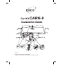
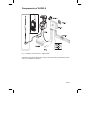
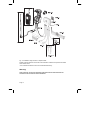
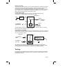
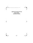
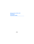
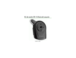
Car Kit CARK-9
Installation Guide
Version 1
Part No. HR8159AA, PS11160AMLAA01
Copyright © 2010 EADS Secure Networks. All rights reserved.
Introduction
This installation guide has been prepared to provide the basic information necessary to
install CARK-9. This guide is not intended to be definitive, because different types and
models of vehicles will require different installation work. The information given is for
general guidance only.
The terms of warranty demand that this car kit be installed by an experienced installer and
that only specified parts are used. An end-user should never attempt to install this car kit
without professional assistance as the installation requires special tools and knowledge.
Please refer to the radio’s User Guide for instructions on the radio’s operation, care and
maintenance, including important safety information.
Note: Read the warnings below before beginning the installation procedure.
WARNINGS
1. ENSURE THAT THE VEHICLE’S BATTERY IS DISCONNECTED BEFORE YOU
START THE INSTALLATION PROCEDURE, AND THAT IT REMAINS
DISCONNECTED DURING THE PROCEDURE.
2. DO NOT SMOKE OR USE OPEN FLAMES WHEN WORKING NEAR THE
VEHICLE’S FUEL SYSTEM.
3. ENSURE THAT THE VEHICLE’S ELECTRICAL CABLES, HYDRAULIC LINES,
FUEL LINES, AND SAFETY EQUIPMENT ARE NOT DAMAGED DURING
INSTALLATION.
4. ENSURE THAT NORMAL CONTROL AND OPERATION OF THE VEHICLE IS NOT
IMPAIRED BY THE INSTALLATION, PARTICULARLY THE BRAKES AND
STEERING. ENSURE THAT AIRBAG OPERATION IS NOT OBSTRUCTED.
5. ELECTRONIC AND OTHER SOPHISTICATED SYSTEMS (e.g. SPEED CONTROL,
ABS ANTI-LOCK BRAKE, FUEL INJECTION-, NAVIGATION-, AND AIR-BAG
SYSTEMS) ARE RELATIVELY IMMUNE TO MALFUNCTION CAUSED BY NEARBY
RADIO TRANSMISSIONS. HOWEVER, SHOULD YOU EXPERIENCE FALSE
OPERATION OF THESE SYSTEMS OR ARE IN ANY DOUBT WHATSOEVER AS
TO THEIR FUNCTIONALITY, PLEASE CONSULT THE VEHICLE’S DEALER.
6. THE CAR KIT IS SUITABLE FOR USE ONLY IN VEHICLES WITH A 12 V
NEGATIVE GROUNDING. USE ON OTHER SUPPLY VOLTAGES OR
ALTERNATIVE POLARITY WILL DAMAGE THE EQUIPMENT.
7. THE RADIO SHOULD NOT BE LEFT SWITCHED ON FOR EXTENDED PERIODS
WITHOUT RUNNING THE VEHICLE’S ENGINE. FAILURE TO COMPLY COULD
DRAIN THE VEHICLE’S BATTERY.
8. SIDE CONNECTOR ACCESSORIES SHOULD BE REMOVED FROM THE
TERMINAL BEFORE THE TERMINAL CAN BE USED IN THE CARKIT
INSTALLATION.
Page 2
Components of CARK-9
Fig. 1. Installation without the DTC-1 Adapter Cable
The CARK-9 includes the above parts. Please note that the items enclosed within broken
lines are not supplied with CARK-9.
Page 3
Fig. 2. Installation using the DTC-1 Adapter Cable
Please note that all items shown above are included in CARK-9 except those enclosed
within broken lines.
*Two of these accessories can be connected simultaneously.
Warning
Side connector accessories should be removed from the terminal before the
terminal can be used in the carkit installation.
Page 4
Component Parts
Advanced Active Holder MCR-4
The holder for the radio is attached to the vehicle’s interior in a convenient position using
the swivel mount HHS-14. The mounting is secured with a screw (included with HHS-14).
The screw recess is covered with the rubber plate.
The cable with the plug-in connector from MCR-4 connects to the PHONE socket in HFU2T. (The other cables from MCR-4 connects to the external TETRA and GPS antennas.)
Swivel Mount HHS-14 and Mounting Plate MKU-1
HHS-14 is a swivel mount which allows for adjustable fixing. MKU-1 is a fixed position
mounting plate.
Advanced HF Unit HFU-2T
The handsfree unit HFU-2T is attached to the vehicle interior using the mounting plate
MKU-1. The mounting is secured with a screw (included with MKU-1).
Power Cable PCH-4J
The power cable connects to the DC socket in HFU-2T and to the vehicle’s power supply.
See the ”Installation” section for more information.
HF Microphone MP-2
The HF microphone connects to the MIC socket in HFU-2T. Twist the plug clockwise to
lock it firmly in place.
HF Speaker HFS-12
The HF speaker connects to the SPEAKER socket in HFU-2T. Twist the plug clockwise to
lock it firmly in place.
Adapter Cable DTC-1
The DTC-1 adapter cable connects to the HFU-2T DATA/HANDSET socket. It provides
for the possibility of connecting to two out of three possible accessories: PTT-1, HSU-1T
and DLR-3T. It comprises specified sockets for DATA and HANDSET connection.
Note that if only one of these three accessories is used, it must be connected directly to
the HFU-2T without using the DTC-1!
External Push to Talk Key PTT-1
The external push to talk key is to be used during a one-way call. The key connects
directly to the HFU-2T DATA/HANDSET socket or to either socket in the DTC-1 Adapter
cable (please refer to DTC-1).
Note that the external push to talk key is not allowed to be installed to a vehicle control
device!
Data Adapter Cable DLR-3T (not supplied)
The data adapter cable enables RS232 data connection to the radio. The cable connects
directly to the HFU-2T DATA/HANDSET socket or to the DTC-1 adapter cable DATA
socket (please refer to DTC-1). For more information, please refer to the user guide for the
data adapter cable.
External Mobile Antenna (not supplied)
An external TETRA-band antenna is recommended for the car kit. It connects to MCR-4.
External GPS Antenna (not supplied)
An external GPS-band antenna is recommended for the car kit. It connects to MCR-4.
Page 5
Handset HSU-1T (not supplied)
The handset HSU-1T offers more privacy during a call. During a one-way call the PTT key
must be used. It connects to the DATA/HANDSET socket of HFU-2T or to the DTC-1
adapter cable HANDSET socket (please refer to DTC-1). For more information, please
refer to the user guide for the handset.
Installation
For an example of installation locations, please see the cover.
Note: Ensure that the battery of the vehicle is disconnected before you start the
installation or start making changes to the installations, and that it remains disconnected
during the installation procedure.
The HFU-2T and the different parts are connected as mentioned in the ”Component Parts”
section.
There are some important aspects that require special attention in positioning car kit
accessories.
The location of the holder should be selected so that the radio's display is easily visible
and that the driver’s attention is not distracted. The location of the holder should allow the
driver to easily reach the keypad. Under no circumstances should the holder in any way
prevent the driver from controlling or operating the vehicle.
The HF microphone should be installed according to the directions in the separate
microphone installation guide. Ensure that the microphone is as close to the driver’s
mouth as possible, and attached to a surface that is mechanically quiet. The microphone
should be mounted at least 3 ft/1 m away from the handsfree unit speaker to avoid
acoustic feedback.
Ensure that the cables are routed as far away as possible from the vehicle’s electronic
systems. This is to prevent interference. Also, ensure that the cables are not subjected to
undue mechanical stress e.g. under seats or against sharp edges.
PCH-4J
The cables from PCH-4J are colour coded. They are listed in the following table in column
A and each cable should be connected to the corresponding item listed in column B.
A
B
Red cable (with 2 amp fuse)
The + voltage on the vehicle’s power supply.
Black cable
The negative GND connection.
Blue cable (with 1 amp fuse)
The +12 V voltage controlled by the vehicle’s ignition key.
(See section ”Ignition Sense IGNS”.)
Yellow cable
Used for car radio muting (XCRM) and is connected to the
car radio. The line goes down to 0 volts during a call. See
section ”Car Radio Muting CRM”.
Green cable (with 1 amp fuse) The motor antenna (AMC). The voltage in this output is
+12 V whenever the phone is on. See section ”Antenna
Motor Control AMC”.
Page 6
Ignition Sense IGNS
The ignition sense feature prevents your car kit from draining the car battery by executing
an auto power off 20 seconds after the ignition key has been turned off. The blue cable
from PCH-4J is used for the ignition sense feature. The use of ignition sense is
recommended to prevent accidental draining of the car’s battery. The cable is connected
via a 1-A fuse to a 12- V supply that is controlled by the ignition key. Do not connect it
directly to the high voltage sections of the ignition circuit.
Car Radio Muting CRM
The car kit offers a feature that can mute the car radio automatically during a
conversation. The following is the circuit diagram for CRM.
Relay (12 V)
GND
CAR
RADIO
87A
30
12 V d.c.
Supply for
car radio
87
85
To XCRM line
(yellow wire)
86
12 V d.c.
Fuse 200 mA
(not supplied)
Another possibility is to use a special muting unit, which mutes the radio by connecting
load resistors to the speaker lines of the car radio.
Antenna Motor Control AMC
The antenna motor control may be used to turn different devices on and off. The maximum
output current is 200 mA; therefore, for example, a motorized antenna must be controlled
via a relay, see diagram below.
Relay (12 V)
87A
12 V d.c.
Supply for
device
30
From AMC line
(green wire)
86
87
85
CONTROLLED
DEVICE e.g.
MOTOR ANTENNA
GND
GND
Fuse 1 A
All installations should take into account any special requirements of the customer.
However, should the customer require an installation that is illegal or unsafe these facts
must be pointed out to the customer and a policy of non-compliance adopted.
Testing
Once installed, the equipment should be tested to ensure that it is operating satisfactorily
and that the position of the units does not in any way impair the driver’s ability to control
and operate the vehicle.
Page 7