1
©
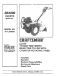
MODEL NO.
917.295651
®
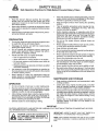
Caution:
Read and follow
all Safety Rules
and Bnstructions
Before Operating
This Equipment
5,0 P
17 INCH TmNEWnDTH
Tn
LLER
WITH
COUNTER ROTATING TINES
o Assembly
o Operation
o Customer Responsibilities
o Service and Adjustments
o Repair Parts
Sears, Roebuck
i
= ==,,
=
and Co., Hoffman
.......................................................................................
Estates, IL 60179 U.S.A.
=
= == =
=
= =H=
SAFETY RULES
Safe Operation
Practices
for Walk-Behind
TRAiNiNG
•
o
Read the Owner's Manual carefully, Be thoroughly
familiar with the controls and the proper use of the
equiprnent.. Know how to stop the unit and disengage
the controls quickly
=
o
Never allow children to operate the equipment. Never
allow adults to operate the equipment without proper
instruction.
=
o
Keep the area of operation clear of all persons, particularly small children, and pets.
o
PREPARATION
°
o
=
o
o
=
=
Thoroughly inspect the area where the equipment is to
be used and remove afl foreign objects.
Disengage all clutches and shift into neutral before
starting the engine (motor)..
Do not operate the equipment without wearing adequate outer' garments° Wear footwear' that will improve footing on slippery surfaces°
Handle fuel with care; it is highly flammable.
°
=
o
•
= Use an approved fuel container:
o Never add fuel to a running engine or hot engine.
=Fitl fuel tank outdoors with extreme care Never fill
fue! tank indoors°
•
o
= Replace gasoline cap securely and clean up spilled
fuel before restarting
Use extension cords and receptacles as specified by
the manufacturer for all units with electric drive motors
or electric starting motors.
Never attempt to make any adjustments while the
engine (motor) is running (except where specifically
recommended by manufacturer).
•
o
OPERATION
.
=
o
Do not put hands or feet near or under rotating parts.
Exercise extreme caution when operating on or crossing gravel drives, walks, or' roads. Stay alert for hidden
hazards or traffic. Do not carry passengers.
After striking a foreign object, stop the engine (motor'),
remove the wire from the spark plug, thoroughly im
spect the tiller for any damage, and repair the damage
before restarting and operating the tiller_
Exercise caution to avoid slipping or falling.
°
•
Rotary Tillers
&
If the unit should start to vibrate abnorrnally, stop the
engine (motor) and check immediately for the cause.
Vibration is generally a warning of trouble°
Stop the engine (motor) when leaving the operating
position_
Take all possible precautions when leaving the machine unattended.
Disengage the tines, shift into
neutral, and stop the engine.
Before cleaning, repairing, or inspecting, shut off the
engine and make certain att moving parts have stopped.
Disconnect the spark plug wire, and keep the wire
away from the plug to prevent accidental starting.
Disconnect the cord on electric motors.
Do not run the engine indoors; exhaust fumes are
dangerous.
Never operate the tiller without proper guards, plates,
or other' safety protective devices in place.
Keep children and pets away°
Do not overload the machine capacity by attempting to
till too deep at too fast a rate.
Never operate the machine at high speeds on slippery
surfaces, Look behind and use care when backing..
Never allow bystanders near the unit.
Use ohly attachments and accessories approved by
the manufacturer of the tiller' (such as wheel weights,
counterweights, cabs, and the like).
Never operate the tiller without good visibility or light.
Be careful when tilling in hard ground. The tines may
catch in the ground and propel the tiller forward. If this
occurs, let go of the handlebars and do not restrain the
machine.
MAINTENANCE
•
o
•
Powered
AND STORAGE
Keep machine, attachments, and accessories in safe
working condition_
Check shear pins, engine mounting bolts, and other
bolts at frequent intervals for proper tightness to be
sure the equipment is in safe working condition.
Never store the machine with fuel in the fue! tank inside
a building where ignition sources are present, such as
hot water and space heaters, clothes dryers, and the
like. Allow the engine to cool before storing in any
enclosure.
Always refer' to the operator's guide instructions for
important details if the tiller is to be stored for an
extended period.
IMPORTANTCAUTION, IMPORTANTS, AND NOTES ARE A MEANS OF ATTRACTING
CAL INFORMATION IN THIS MANUAL°
IMPORTANT:
POSSIBILITY
CAUTION: Look for this symbol to point
out important
safety precautions.
It
means --Attention!
Become Alert! Your
safety is involved.
ATTENTION TO IMPORTANT OR CRITI_
USED TO ALERT YOU THAT THERE
OF DAMAGING THIS EQUIPMENT.
IS A
NOTE: Gives essential information that will aid you to better
understand, incorporate, or execute a particular set of instruclions.
2
CONGRATULATIONS
on your purchase of a Sears Tiller.
It has been designed, engineered and manufactured to
give you the best possible dependability and performance.
PRODUCT
Should you experience any problems you cannot easily
remedy, please contact your nearest authorized Sears
Service Center/Department.
They have competent, welltrained technicians and the proper tools to service or repair
this uniL
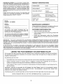
HORSEPOWER:
50 HP
DISPLACEMENT:
12_57cu, in
GASOLINE CAPACITY:
4 Quarts
Unleaded Regular
P}ease read and retain this manual The instructions will
enable you to assemble and maintain your tiller properly.
Always observe the "SAFETY RULES".
MODEL
NUMBER
SPECIFICATIONS
OIL (APFSF/SG) :
(CAPACITY: 20 oz,)
SAE 30 (Above 32"F)
SAE 5W-30 (Below 32°F)
SPARK PLUG :
(GAP: _030")
Champion
RJ19LM (STD361458)
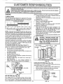
917.295651
SERIAL
NUMBER
MAINTENANCE
AGREEMENT
A Sears Maintenance Agreement is available on this product. Contact your nearest Sears store for details,
DATE OF
PURCHASE
THE MODEL AND SERIAL NUMBERS WILL BE
FOUND ON THE MODEL PLATE ATTACHED TO
THE TOP OF THE TRANSMISSION,
YOU SHOULD RECORD BOTH SERIAL NUMBER
AND DATE OF PURCHASE AND KEEP IN A SAFE
PLACE FOR FUTURE REFERENCE
CUSTOMER
RESPONSIBILITIES
-
Read and observe the safety rules_
o
Follow a regular schedule in maintaining, caring for and
using your tiller..
Follow the instructions
under the "Customer
Responsibilities" and "Storage" sections of this Owner's
Manual..
.
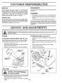
IMPORTANT,"
THIS UNIT IS EQUIPPED WITH AN INTERNAL COMBUSTION
ENGtNE AND SHOULD NOT BE USED ON
OR NEAR ANY UNIMPROVED
FOREST-COVERED,
BRUSH-COVERED
OR GRASS COVERED
LAND UNLESS THE
ENGINE'S EXHAUST
SYSTEM IS EQUIPPED WITH A SPARK ARRESTER
MEETING APPLICABLE
LOCAL OR STATE
LAWS (IF ANY), IF A SPARK ARRESTER
iS USED, tT SHOULD BE MAINTAINED
IN EFFECTIVE WORKING ORDER BY
THE OPERATOR
IN THE STATE OF CALIFORNIA
THE ABOVE IS REQUIRED
BY LAW (SECTION 4442 OF THE CALIFORNIA
PUBLIC
RESOURCES
CODE).
OTHER STATES MAY HAVE SIMILAR LAWS.
FEDERAL LAWS APPLY ON FEDERAL
LANDS.
SEE YOUR SEARS AUTHORIZED
SERVICE CENTER/DEPARTMENT
FOR SPARKARRESTER
REFER TO THE REPAIR
PARTS SECTION OF THIS MANUAL FOR PART NUMBER
LiMiTED
TWO YEAR WARRANTY
ON CRAFTSMAN
TILLER
For two years from date of purchase, when this Craftsman Tiller is maintained, lubricated, and tuned up according to
the operating and maintenance instructions in the owner's manual, Sears will repair free of charge any defect in
material or workmanship.
This Warranty does not cover:
.
Expendable items which become worn during normal use, such as tines, spark plugs, air cleaners and belts.
•
Repairs necessary because of operator abuse or negligence, including bent crankshafts
maintain the equipment according to the instructions contained in the owner's manual.
•
If this Craftsman Tiller is used for commercial or rental purposes, this Warranty applies for only 30 days from the
date of purchase.
and the failure to
WARRANTY SERVICE IS AVAILABLE BY RETURNING THE CRAFTSMAN TILLER TO THE NEAREST SEARS
SERVICE CENTER/DEPARTMENT
IN THE UNITED STATES THIS WARRANTY APPLIES ONLY WHILE THIS
PRODUCT iS IN USE IN THE UNITED STATES°
This Warranty gives you specific legal rights, and you may also have other rights which vary from state to state.
SEARS, ROEBUCK AND CO., D/817 WA, HOFFMAN ESTATES,
ILLINOIS 60179
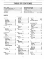
TABLE OF CONTENTS
SAFETY RULES ............................................................
2
CUSTOMER RESPONSIBILITIES ...................... 3,13-15
PRODUCT SPECIFICATIONS ....................................... 3
WARRANTY ..................................................................
3
ACCESSORIES .............................................................
5
ASSEMBLY ...............................................................
6-8
OPERATION ............................................................
9-12
MAINTENANCE SCHEDULE .....................................
13
SERVICE & ADJUSTMENTS ................................
15-18
STORAGE ...................................................................
19
TROUBLESHOOTING .................................................
20
REPAIR PARTS-TILLER .......................................
21-27
REPAIR PARTS-ENGINE ......................................
28-33
SERVICE/PARTS ORDERING ............... BACK COVER
aNDEX
A
Engine (cont'd)
Lubrication .......................................
14
Accessories ...........................................................
5
Oil Level ...........................................
11
Adjustments:
Oil Type ................................ 11,14
Carburetor _.....................................
18
Spark Plug ................................. 15
Depth Stake ............................... 10
Starting ............................................
12
Handle Height ........................................
15
Stopping ............................................
10
Side Shields ............................. 11
Storage ..............................................
19
Throttle ....................................................
18
Winter Operation ........................ 14
Tines ......................................................
17
V-Belt (Ground Drive) ............. 16
F
Air Cleaner ..................................... 14
Fuel:
Filling Tank ................................ 11
B
Storage ...........................................
:.= 19
Belt:
Type ............................................ 11
Belt Guard ................................ 16
Finish:
Repair Parts .......................................
22
Maintenance .......................................
15
V-Belt (Ground Drive) ................16
R
Repair Parts:
Tiller ..................................... 21-27
Engine ............................................
28-33
Rules for Safe Operation ....................2
S
Service & Adjustments:
Carburetor° .............................. 18
Handle Height .......................... 15
Side Shields .............................. 11
Throttle .........................................................
18
Tines ....................................................
17
V-Belt (Ground Drive) ............... t6
Whee s .................................
15
Service:
Repair Parts ....................... 21-33
Service Record ...............................
13
H
C
Shear Pins:
Handle:
Operation ................................. 12
Cooling System ................................. 14
Height Adjustment .......................15
Repair Parts ..............................................
26
Controls:
Repair" Parts .......................................
21
Spark Plug:
Choke ....................................................................
9
Gap ...............................................................
3
Throttle ..................................................
9
L
Maintenance
...........................
15
Drive (Tines) .............................................
9
Lubrication:
Storage:
Cultivating ..............................................
12
Lubrication Chart ...................... 13
FueI System ............................ 19
Customer Responsibilities:
Engine ......... :....................................
14
Tiller .............................................................
19
Air Cleaner _............................. 14
Cooling System ..............................
14
M
Finish ......................................... 15
Muffler:
Maintenance Schedule ........... 13
Tilling ..........................................
10,12
Maintenance ....................... ........15
Muffler .....................................
15
Tines:
Spark
Arrester ................................3
Oil Change .............................. 14
Arrangement/Replacement
..... 17
Spark Plug ............................... 15
Operation .................................. t0
O
Tines ........................................ 17
Repair Parts ............................... 26
Transmission .......................... 15
Oil:
Shear Pins .....................................
12
V-Belt (Ground Drive) .............. 16
Level .............................................. 11
Transmission:
Type ............................................
11,14
Maintenance ..................................
15
D
Operation:
Repair Parts ............................ 24
Cultivatin( .....................................12
Depth Stake:
Troubleshooting ..........................................
20
Fill Fuel Tank ...................................
11
Adjustment ................................ 10
Transporting
..................................
11
Repair Parts ................................ 25
Starting Engine ........................ 12
Stopping Tines & Engine ........ 10
W
Tilling ..............................................
10
E
Tilling Hints ...................................12
Warranty
..............................................
3
Engine:
Tine Operation
10
Wheels:
Air Cleaner _...................................14
Transporting Tiller ................... 11
Removal ........................................15
Cooling System ....................................
14
Winter' Operation .........................14
Repair Parts .....................................
23
Fuel Type ................................................
11
............................
4
iii
i ii iii ,i i,,,11,1
_
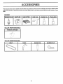
ACCESSORmES
..........................
i, i, ,11,,i
These accesso ries were available when the tiller was purchased. They are also available at most Sears Retail outlets
and Service Centers. Most Sears Stores can order repair parts for you when you provide the model number of your
tiller.
ENGINE
MUFFLER
SPARK PLUG
,,
TILLER
_,=
...............
AIR FILTER
ENGINE OIL
GAS CAN
STABILIZER
H,III,,
PERFORMANCE
FURROW
TILLER
....
OPENER
MAINTENANCE
BELT
TINES
SHEAR PIN
O
C
HAIRPIN
CLIP
......
i,
,,
i
i
................................................
,i
ASS
i,
,
LY
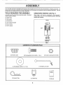
Your new tiller has been assembled at the factory with exception of those parts left unassembted for =shipping purposes. To
ensure safe and proper operation of your' tiller all parts and hardware you assemble must be tightened securely° Use the
correct tools as necessary to insure proper tightness,
TOOLS REQUIRED
FOR ASSEMBLY
OPERATOR'S
A socket wrench set will make assembly easier= Standard
wrench sizes are listed_
(1) Utility knife
POSITION
(See Fig. 1)
When right or left hand is mentioned in this manual, it
means when you are in the operating position (standing
behind tiller handles).=
(1) Wire cutter
FRONT
(1) Screwdriver
(1) Tire pressure gauge
(1) Pair'of pliers
(1) 9/16" wrench
LEFT
RIGHT
OPERATOR'S
POSITION
FIG. 1
CONTENTS
(2) Handle Locks
OF HARDWARE
PACK
(2) Carriage Bolts 3/8-16 UNC x I GL 5
(2) Center Locknuts 3/8-16 UNC
©
(!) Flat Washer 13132 x 1 x 11 Ga.
(2) Hairpin Clips
(1) Handle Lock Lever
(1) Cable Clip
(1) Manual
i
LY
i, ,lllllU i
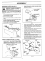
UNPACKING
i
,
CARTON
i.....
, n,,u ....................
o
(See Fig. 2)
, ,i ii, ,i,1,,i,,,i,,lli i
_€_
staples when handling or disposing of
CAUTION: material.
Be careful of exposed
cartoning
i i u ,, i
i, i,,,,,,irl,i
Grasp handle assembly. Hold in"up" position. Be sure
handle lock remains in gearcase notch, Slide handle
assembly into position.
!
HANDLE ASSEMBLY
"UP*' POSITION
!
IMPORTANT:
WHEN UNPACKING AND ASSEMBLING
TILLER, BE CAREFUL NOT TO STRETCH OR KINK
CABLES.
=
While holding handle assembly, cut cable ties securing
handle assembly to top frame and depth stake. Let
handle assembly rest on tiller,
•
Remove top frame of carton.
=
Slowly ease handle assembly up and place on top of
carton,
o
Cut down right hand front and right hand rear corners
of carton, lay side carton wall down,
,
Remove packing material from handle assembly,
•
Separate shift rod from handle assembly°
TIGHTEN HANDLE
LOCK LEVER TO
HOLD
LOOSEN HANDLE
LOCK LEVER TO
MOVE
FIG. 4
SHIFT ROD
HANDLE
ASSEMBLY
FIG. 2
INSTALL
•
HANDLE
(See Figs.
Rotate handle assembly down, Insert rear carriage
bolt first, with bolt head on LH.. side of tiller (See Fig. 5).
=
Insert front carriage bolt with care, since space for
installation is limited.
o
Lower the handle assembly, Tighten locknuts on bolts
so handle moves with some resistance.
,
Place flat washer on threaded end of handle Iocktever_
•
Insert handle lock lever through handle base and
gearcaseo Screw in handle lock lever just enough to
hold tever in place,
°
Insert second handle lock (with teeth inward) in the slot
of the handle base (just inside of washer).
-
With handle assembly in lowest position, securely
tighten handle lock lever by rotating clockwise, Leaving handle assembly in lowest position will make it
easier to remove tiller from carton.
3, 4, and 5)
HANDLE
LOCK
Insert one handle lock (with teeth facing outward) in
gearcase notch. (Apply grease on smooth side of
handle lock to aid in keeping lock in place until handle
assembly is lowered into position.i)
VIEW FROM R,H, SIDE OF TILLER
HANDLE
o
SLOT
FLAT
WASHER
CARRIAGE
BOLT
HANDLE
LOCK
LEVER
ASSEMBLY
REAR
CARRIAGE
BOLT
LOCKNUTS
HANDLE
BASE
FIG. 5
FIG. 3
7
H", HIH ='H= H
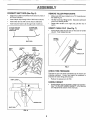
CONNECT
,','HN"= I
SHIFT
RO D (See Fig. 6)
REMOVE
TILLER
FROM CRATE
o
insert end of shift rod farthest from bend into hole of
shift lever indicator,
-
Make sure shift lever indicator is in "N" (neutral) position (See Fig° 6)
o
o
Insert hairpin clip through hole of shift rod to secure.
Insert other end of shift rod into hole in shift lever_
=
Tilt tiller forward by lifting handle, Separate cardboard
cover from leveling shield,.
°
Insert second hairpin clip through hole of shift rod,
=
Rotate tiller' handle to the right and pull tiller out of
carton.
ATTACH THIS END
TO SHIFT LEVER
ATTACH THIS
END TO SHIFT
INSERT
o
INDICATOR
LEVER _
!
'_
CLIP
(See Fig. 7)
Insert plastic cable ciip into hole on the back of handle
column,. Push cables into clip.
,i
.....
HANDLE
COLUMN
\
SHIFT ROD
SHIFT
CABLE
SHIFT
LEVER
INDICATOR
HAIRPIN
CABLES
CLIP
FIG. 7
CHECK
TIRE PRESSURE
The tires on your unit were overinflated at the factory for
shipping purposes. Correct and equa} tire pressure is
important for best tilling performance.
,
SHIFT LEVER ,_
Reduce tire pressure to 20 PSL
HANDLE
=
HAIRPIN CLIP
SHIFT ROD
FIG. 6
HEIGHT
Hand!e height may be adjusted to better suit operator°
(See q'O ADJUST HANDLE HEIGHT" in the Service
and Adjustments section of this manual),.
.........................
ii1,1
.................
_1
OPERATmON
i,,
,i, ,,i,,,lll
,i,lll
i
i,,i
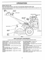
KNOW YOUR TILLER
READ THIS OWNER'S
MANUAL AND SAFETY RULES BEFORE OPERATING YOUR TILLER.
Compare the illustrations with your tiller to familiarize yourself with the location of various controls and adjustments. Save
this manual for future reference,
DRIVE
CONTROL
BAR
THROTTLE
CONTROL
SHIFT LEVER
CHOKECONTROL
FUEL SHUT-OFF
VALVE
SHIFT LEVER
INDICATOR
RECOIL
STARTER
HANDLE
DEPTH STAKE
SHIELD
_
:::
STOP SWITCF
:3
LEVELING
{_
OUTER
SIDE
SHIELD
FIG. 8
MEETS ANSI SAFETY
REQUIREMENTS
Our tillers conform to the safety standards of the American National Standards institute,
CHOKE CONTROL - Used when starting a cold engine°
CULTIVATING
DEPTH STAKE - Controls depth at which titler will dig°
LEVELING SHIELD - Levels tilled soil,.
DEPTH STAKE - Controls forward speed and the depth at
which the tiller will dig,,
OUTER SIDE SHIELD - Adjustable to protect small plants
from being buried.
DEPTH STAKE PIVOT _ Controls pivoting action of depth
stake,,
RECOIL STARTER HANDLE - Used to start the engine.
DRIVE CONTROL
FORWARD
direction1
SHIFT [.EVER - Used to shift transmission
BAR - Used to engage tines,
TINE CONTROL
REVERSE TINE CONTROL
direction_
SHIELDS _ Engages tines
gears°
SHIFT LEVER INDICATOR - Shows which gear the transmission ts lno
- Engages tines in forward
THROTTLE
- Engages tines in reverse
CONTROL - Controls engine speed,
STOP SWITCH - Used to stop engine_ Must be in "ON"
position when starting engine.
9
'M='H_',I'=
' H=, =
"=l!lll= HH'H
=
OPERATNON
......................
111,111111111=
= ,I=HHH=H=,
_=_
result in severe eye damage. Always wear safety glasses or eye shields before starting
your tiller and while tilling. We recommend a wide vision safety mask over the spectacles
The
operationsafety
of any
tiller can result in foreign objects thrown into the eyes, which can
or standard
glasses.
llll
llliHi,
HH H=
I,=,,,,I,,,l=
,,HHH= 'H
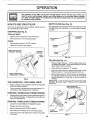
HOW TO USE YOUR TALLER
DEPTH
Know how to operate all controls before adding fuel and
oil or attempting to start engine.
The depth stake can be raised or lowered to allow you more
versatile tilling and cultivating, or' to more easily transport
tour tiller.
STOPPING
STAKE
(See Fig. 10)
(See Fig. 9)
TINES AND DRIVE
.
Release drive control bar to stop movement.
•
Move shift lever to "N" (neutral) positien.,
POSITION
SHALLOWEST
TILLING
ENGINE
•
Move throttle control to "STOP" position°
°
Never use choke to stop engine.
TILLING
DRIVE CONTROL BAR
"ENGAGED"
POSiTiON
STAKE
DEPTH/_
SHIFT
LEVER
FIG. 10
TILLING (See Fig. 11)
DRIVE CONTROL BAR
"DISENGAGED"
POSiTiON
FIG. 9
TINE OPERATION
- WITH WHEEL
Always release drive control bar before moving shift
lever into another position..
°
Tine movement is achieved by moving shift lever to "T"
(tili) position and engaging drive control bar.
FORWARD
°
-WHEELS
ONLY/TINES
Release depth stake pin. Pull the depth stake up for
increased tilling depth. Place depth stake pin in hole of
depth stake to lock in position,
•
Place shift lever indicator in "T" position_
.
Hold the drive control bar against the handle to start
tilling movement., Tines and wheels will both turn_
=
Move throttle control to "FAST" position for deep tilling,
To cultivate, throttle control can be set at any desired
speed, depending on how fast or' slow you wish to
cultivate,.
IMPORTANT:
ALWAYS RELEASE DRIVE CONTROL BAR
BEFORE
MOVING
SHIFT
LEVER
INTO ANOTHER
POSITION
DRIVE
-
°
DEPTH STAKE PIN
"RELEASED"
POSiTiON
STOPPED
Release drive control bar and move shift lever indicator
to "F" (forward) position, Engage drive control bar and
tiller will move forward.
REVERSE
- WHEELS
ONLY/TINES
STOPPED
°
DO NOT STAND DIRECTLY BEHIND TILLER.
=
Release the drive control bar.
o
Move throttle control to "SLOW" position.
o
Move shift lever indicator to "R" (reverse) position°
•
Hold drive control bar against the handle to start tiller
movement
"LOCKED"
POSITION
NUT"A"
OUTER
SIDE SHIELD
NUT"B"
FIG. 11
10
........
i,,Uln
i ,
, i, i,,,11,,,11,
¸
OPERATmON
TURNING
•
o
Release the drive control bar.
o
Place shift lever indicator in "F" (forward) position+
Tines will not turn.
°
Engine oil should be to point of overflowing+ For
approx!mate capacity see PRODUCT SPECIFICATIONS on page 3 of this manual All oil must meet
A+P.I. Service Classification SF or SG+
,
For cold weather operation you should change oil for
easier starting (See oil viscosity chart in the Customer
Responsibilities section of this manual)..
o
To change engine oil, see the Customer Responsibilities section in this manual.
Move throttle control to "SLOW" position.
o
Lift handle to raise tines out of ground.
°
Swingthe handle in the opposite direction you wish to
turn, being careful to keep feet and legs away from
tines°
When you have completed your turn-around, release
the drive control bar and lower handle. Place shift lever
in "T" (till) position and move throttle control to desired
speed.. To begin tilling, hold drive control bar against
the handle.
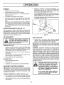
OUTER
SIDE SHIELDS
OIL
(See Fig. 11)
The front edges of the outer side shields are slotted so that
the shields can be raised for deep tilling and lowered for
shallow tilling to protect small plants from being buried.
Loosen nut "A" in slot and nut "B'L Move shield to desired
position (both sides)+ Retighten nuts.
FILLER
PLUG
PLUG
FIG. 12
TO TRANSPORT
ADD GASOLINE
CAUTION: Before lifting or transporting, allow tiller engine and muffler to
cool. Disconnect spark plug wire. Drain
gasoline from fuel tank.
|
!
o
Fill fuel tank. Use fresh, clean, regular unleaded
gasoline.. (Use of leaded gasoline will increase carbon
and lead oxide deposits and reduce valve life+
IMPORTANT: WHEN OPERATING IN TEMPERATURES
BELOW 32°F (0°C), USE FRESH, CLEAN, WINTER GRADE
GASOLINE TO HELP INSURE GOOD COLD WEATHER
STARTING.
i
AROUND THE YARD
°
Release the depth stake pin.. Move the depth stake
down to the top hole for transporting the tiller_ Place
depth stake pin in hole of depth stake to lock in position_
This prevents tines from scuffing the ground..
•
Place shift lever indicator in "F" (forward) position for
transporting.
,
Hold the drive control bar against the handle to start
tiller movement. Tines will not turn+.
•
Move throttle control to desired speed..
WARNING:
Experience indicates that alcohol blended
fuels (called gasohol or using ethanol or methanol) can
attract moisture which leads to separation and formation of
acids during storage. Acidic gas can damage the fuel
system of an engine while in storage. To avoid engine
problems, the fuel system should be emptied before storage of 30 days or longer. Drain the gas tank, start the
engine and let it run untit the fuel lines and carburetor are
empty. Use fresh fuel next season. See Storage section
of this manual for additionat information. Never use engine
orcarburetor cleaner products in the fuel tank or permanent
damage may occur.
AROUND TOWN
•
,
Disconnect spark plug wire..
Drain fuel tank..
,
Transport in upright position to prevent oil Ieakage+
BEFORE
STARTING
i
i_
ENGINE
IMPORTANT:
BE VERY CAREFUL NOT TO ALLOW DIRT
TO ENTER THE ENGINE WHEN CHECKING
OR ADDING
OIL OR FUEL. USE CLEAN OIL AND FUEL AND STORE
tN APPROVED,
CLEAN, COVERED CONTAINERS
USE
CLEAN FILL FUNNELS
CHECK
ENGINE
OIL
LEVEL
Do not overfill. Wipe off any spilled oil
or fuel. Do not store, spill or use gasoline near an open flame,
(See Fig. 12)
•
The engine in your unit has been shipped, from the
factory, already filled with SAE 30 summer weight oil+
•
With engine level, clean area around oil filler plug and
remove plug.
of fuel tank to prevent spills and to
allow
for fuelFillexpansion.
If gasoline
is
CAUTION:
to within 112
inch of top
accidentally
spilled,
move machine
away from area of spill. Avoid creating
any source of ignition until gasoline
vapors have disappeared.
11
OP RATION
H,INI
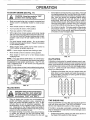
TO START
ENGINE
(See Fig. 17)
...........................
mmH,
.
Place throttle control in "FAST" position..
o
Turn fuel shut=off valve to "ON" position.
•
Push stop switch to "ON" position,
•
With engine fully choked, grasp recoil starter handle
with one hand and grasp tiller handle with other hand..
Putl rope out slowly until engine reaches start of compression cycle (rope will pull slightly harder at this
point)..
o
Pull recoil starter handle quickly. Do not let starter
handle snap back against starter. Repeat if necessary
in half choked position.
•
When engine starts, slowly move choke control to
"RUN" position as engine warms up.
NOTE:
=
Do not lean on handle° This takes weight off the wheels
and reduces traction. To get through a really tough
section of sod or hard ground, apply upward pressure
on handle or lower the depth stake.
!
Make sure spark plug wire is properly connected and
access cover is completely closed to create proper
seal.
N !l
Soil conditions are important for proper tilling. Tines will
not readily penetrate dry, hard soil which may contribute to excessive bounce and difficult handling of your
tiller° Hard soil should be moistened before tilling;
however, extremely wet soil will "ball-up" or clump
during tilling. Wait until the soil is less wet in order to
achieve the best results.. When tilling in the fall, remove
vines and long grass to prevent them from wrapping
around the tine shaft and slowing your' tilling operations
|
o
,,HI
°
Hi,11
CAUTION:when
position
Keep
starting
tine control
engine.in "OFF"
II
A warm engine requires less choking to start.
o
Move throttle control to desired running position.
o
Allow engine to warm up for a few minutes before
engaging tines,
NOTE: If at a high altitude (3000 feet) or in cold temperatures (below 32°F), the carburetor fuel mixture may need to
be adjusted for best engine performance. See "TO ADJUST CARBURETOR" in the Service and Adjustments
section of this manual.
NOTE: Ifengine does not start, seetroubleshooting
points,
FIG. 14
CULTIVATING
Cultivating is destroying the weeds between rows to prevent them from robbing nourishment and moisture from the
plants_ At the same time, breaking up the upper' layer of soil
crust wilt help retain moisture in the soil. Best digging depth
is 1" to 3" Lower the outer side shields to protect small
plants from being buried.
=
FUEL
SHUTOFF
VALVE
Cultivate up and down the rows at a speed which wit!
allow tines to uproot weeds and leave the ground in
rough condition, promoting no further growth of weeds
and grass (See Fig. 15).
STOP SWITCH
©
O
O
O
CHOKECONTROL
FIG. 13
TILLING
HINTS
CAUTION: Until you are accustomed to
handling your tiller, start actual field
use with throttle in slow position (midway between "FAST" and "IDLE").
=
=
Tilling is digging into, turning over, and breaking up
packed soil before plantirlg. Loose, unpacked soil
helps root growth. Best tilling depth is 4" to 6". A tiller
will also clear the soil of unwanted vegetation.. The
decomposition of this vegetable matter enriches the
soil.. Depending on the climate (rainfall and wind) it
may be advisable to till the soil at the end of the growing
season to further condition the soil.
For easier handling of your tiller, leave about 8 inches
of untilled soil between the first and second tilling
passes. The third pass will be between the first and
12
second (See Fig. 14).
OIO
©iC;
OIO
OIO
O1©
OIO
OIO
OIO
FIG. 15
TINE SHEAR
PINS
The tine assemblies on your tiller are secured to the tine
shaft with shear pins (See "FINE REPLACEMENT" in the
Service and Adjustments section of this manual)°
If the tiller is unusually overloaded or jammed, the shear
pins are designed to break before internal damage occurs
to the transmission.
-
If shear pin(s) break, replace only with those shown in
the Repair Parts section of this manual
--
u
CUSTOMER
i.i.
RESPONSm
i
i i i... u n n.lUi.,i......HlU,,
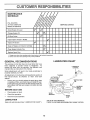
SCHEDULE
FH.L
_NDATES
AS YOU COMPLETE
REGUSERV,OE
R
_'_,
/_
,k/._,_
.............
/
Check Engine Oil Level
6/'
Change Engine Oi_
6/
6//'
Oil Pivot Points
S ERVICEDATES
,,
_'1,2
6/
, n u i,u im,mml
Inspect Spark Arrester / Muffler
Inspect Air Screen
6/
6/
Clean or Replace Air Cleaner Cartridge
6/
Clean Engine Cylinder Fins
Replace Spark Plug
6/
1 - Change mere often when operating under a heavy load or in high ambient temperatures
2 - Service more o_ten when operating in dirty or dusty conditions
GENERAL
LUBRiCATiON
RECOMMENDATIONS
CHART
The warranty on this tiller does not cover items that have
been subjected to operator abuse or negligence,
To
receive fult value from the warranty, the operator must
maintain tiller as instructed in this manual,
* THROTTLE
CONTROL
Some adjustments will need to be made periodically to
properly maintain your tillero
All adjustments in the Service and Adjustments section of
this manual should be checked at least once each
season,
** ENGINE
* DEPTH STAKE
PIN
Once a year you should replace the spark plug, clean
or replace air filter, and check tines and belts for wear.
A new spark plug and clean air filter assure proper airfuel mixture and help your engine run better and last
longer
BEFORE
EACH
_
SHIELD
HINGES
USE
=
Check engine oil level,
o
Check tine operation,
o
Check for loose fasteners
* IDLER
BRACKET
WHEEL
HUB
LUBRICATION
Keep unit well lubricated (See "LUBRICATION
* LEVELING
* SAE 30 OR 10W-30 MOTOR OIL
CHART") ,,
** REFER TO CUSTOMER
13
RESPONSIBILITIES
"ENGINE"
SECTION
i1,,,11,111111,,i,,
i
CUSTO
i1,11,ll!llll
i, iiii i i
,,,i,ii,iii1,,11,
,,
i,illl,!,
RESPON
i
E$
i1,11,
Disconnect spark plug wire before performing any maintenance (except carburetor adjustment) to prevent
accidental starting of engine.
Prevent fires! Keep the engine free of grass, leaves, spilled oil, or fuel Remove fuel from tank before tipping
unit for maintenance. Clean muffler area of all grass, dirt, and debris.
Do not touch hot muffler 0r cylinder fins as contact may cause burns.
I,II,Hl','!l
ENGINE
LUBRICATION
Use only high quality detergent oil rated with API service
classification SF or SGo Select the oil s SAE viscosity grade
accordinq to your expected temperature,
SAE VISCOSITY GRADES
_F
*20_
0"
30 _
32_ 40_
60_
......
8Q_
100_
°c .3'o,.
._oo -lo,
`0°
1oo
_o°
30° 4'0"
TEUPEaATURE
_A._EANTICtPATEO
BEFO.E
NEXT
OILCaANaE
FIG. 16
NOTE: Afthough multi-viscosity oils (5W-30, 10W-30, etc)
improve starting in cold weather', these multi-viscosity oils
wilt result in increased oil consumption when used above
32°F (0°C)_ Check your engine oil level more frequently to
avoid possible engine damage from running low on oil.
Change the oil after the first two hours of operation and
every 25 hours thereafter or at least once a year if the tiller
is not used for 25 hours in one year.,
Check the crankcase oil level before starting the engine
and after each five (5) hours of continuous use_ Add SAE
30 motor oil or equivalent. Tighten oil filler plug securely
each time you check the oil level,,
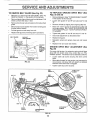
TO CHANGE ENGINE OIL (See Figs. 16 and 17)
Determine temperature range expected before oil change,
All oil must meet API service classification SF or SG
°
Be sure tiller'is on level surface°
o
Oil will drain more freely when warm_
=
Use a funnel to prevent oil spifl on tiller, and catch oil in
a suitable container°
o
Remove drain plug.
o Tip tiller' forward to drain oil.
= After oil has drained completely, replace oil drain plug
and tighten securely,_
o
Remove oil filler plug,. Be careful not to allow dirt to
enter the engine_
°
Refill engine with oil
See "CHECK ENGINE OIL
LEVEL" in the Operation section of this manual
I
Illllll,
II I
Service ah' cleaner more often under' dusty conditions°
•
Loosen air cleaner' cover screws. Remove cover' and
air cleaner assembly from base.
o
Remove air cleaner asssembly from inside cover' and
disassemble.
TO SERVICE PRE-CLEANER
o Wash it in liquid detergent and water°
= Squeeze it dry in a clean cloth.
°
Saturate it in engine oil,, Wrap it in clean, absorbent
cloth and squeeze to remove excess oil
TO SERVICE CARTRIDGE
o Gently tap the flat side of the paper cartridge to dislodge dirt_, Do not wash the paper cartridge or use
pressurized aim', as this wilt damage the cartridge°
Replace a dirty, bent, or' damaged cartridge.
•
Re-assemble retainer on we-cleaner and cartridge
(screen side of pre-cleaner toward cartridge pleats),,
Place assembly into cover,
o Insert tabs on cover into slots in base and tighten cover
.............
screws securely.
CAUTION:
Petroleum solvents, such
as kerosene, are not to be used to clean
cartridge, They may cause deterioration of the cartridge, Do not oil cartridge.
Do not use pressurized air to
clean or dry cartridge,
IIII,IH..................
IIII,
PRE-CLEANER
COVER
I
I
TAB
BASE
CARTRIDGE
RETAINER
/
, COVER
SCREWS
DUAL ELEMENT"CARTRIDGE
AIR CLEANER
FIG. 18
COOLING
SYSTEM
(See Fig. 19)
Your engine is air cooled° For proper engine performance
and long life keep your engine clean.
= Clean airscreen frequently using astiff-bristled brush.
o
Remove blower housing and clean as necessary.
°
Keep cylinder fins free of dirt and chaf[
DRAIN
PLUG_
OIL LEVEL
OIL
, BLOWER
HOUSING
PLUG
FIG. 17
AIR FILTER
(See Fig. 18)
SCREEN
Your engine will not run properly using a dirty air filteL
Clean the foam pre-cleaner after' every 25 hours of operation or every season, Service paper cartridge every 100
hoursof operation or every season, whichever occurs first. 14
FIG. 19
............
i
,
i nn,un,,,u,u,,llll...................
CUSTOMER
BaLUTmES
MUFFLER
TRANSMISSION
Do not operate tiller without muffler Do not tamper with
exhaust system,, Damaged mufflers or spark arresters
could create a fire hazard., Inspect periodically and replace
if necessary, tf your engine is equipped with a spark
arrester screen assembly, remove every 50 hours for
cleaning and inspection,, Replace if damaged,,
Your transmission is sealed and will only require lubrication
if serviced,,
SPARK
CLEANING
PLUG
Replace spark plugs at the beginning of each tilling season
or after every 50 hours of use, whichever comes first. Spark
plug type and gap setting is shown in "PRODUCT SPECIFICATIONS" on page 3 of this manual
u, n ,nnl,lll
,,
Clean engine, wheels, finish, etc.. of all foreign matter°
•
Keep finished surfaces and wheels free of allgasoline,
oil, etc.
-
Protect painted surfaces with automotive type wax.
We do not recommend using a garden hose to clean your
unit unless the muffler, air filter and carburetor are covered
to keep water out.. Water in engine can result in a shortened
engine Iife..
...........................................................
inlUl,,,i,rllllrrl
SERVICE
i
CAUTION: Disconnect
contact with plug,
, i iii
AND ADJU
m.i
spark plug wire from spark
HANDLE
HEIGHT
(See Fig. 20)
Select handle height best suited for your tilting conditions,=
Handle height will be different when tiiler digs into soil,
.
First loosen handle lock lever,
o
Handle can be positioned at different settings between
"HIGH" and "LOW" positions,
Retighten handle lock lever securely after adjusting,,
'
HANDLE (HIGH
POSITION)
J
_.
WHEEL
o
Place blocks under transmission
tipping.
to keep tiller from
.
Remove outer side shield by removing nuts"A" and "B".
o
Remove inner side shield by removing nuts "C" and
o
Remove hairpin clip and clevis pin from wheel,.
o
Remove wheel and tire,
°
Repair tire and reassemble.
CLEVIS
HANDLE
LOCK
HAIRPIN
CLIP
NUT "A"
FIG. 20
TIRE CARE
i . I,HI IIIHPlII,I..
I _k
I _
CAUTION: When mounting tires, unless beads are seated, overinflation
I _
can cause an explosion,
!
Maintain 20 pounds of tire pressure,, if tire pressures
are not equal, tiller will pull to one side.
Keep tires free of gasoline or oil which can damage
rubber
15
!
(See Fig. 21)
HANDLE (LOW
POSITION)
o
t
ENTS
plug and place wire where it cannot come into
TO REMOVE
TO ADJUST
i
n ..................
TILLER
°
=
INNER SIDE
SHIELD
F
OUTER
SIDE
SHIELD
NUT "B'"
FIG. 21
iiiii1,,11,,1111,11,,11,1,,,,11,1
,, ,i
iiii
SERVSCE AN
TO REMOVE
BELT GUARD
TO REPLACE
GROUND
Figs. 22 and 23)
(See Fig. 22)
Remove LH, inner and outer side shields (See "TO
REMOVE WHEEL" in this section of this manual),
,
Remove hair pin clip and clevis pin from left wheel
wheel out from tiller' about I inch..
•
Remove hex nut and washer from bottom of belt guard
(located behind whee!)_
,
Pull belt guard out and away from unite
"
Repface belt guard by reversing above procedure..
CAPNUT
AND WASHER
HEX NUT
AND
WASHER
(LOCATED
BEHIND
TIRE)
CAP NUT
°
Loosen belt guides "A" and "B" and also nuts "C" and
o
Remove old belt by slipping from engine pulley first..
u
Place new belt in groove of transmission pulley and
into engine pulley BELT MUST BE IN GROOVE ON
TOP OF IDLER PULLEY NOTE POSITION OF BELT
TO GUIDES.
=
Tighten belt guides "A" and "B" and nuts "C" and "D".
-
Check belt adjustment as described below.
=
Replace belt guard.
=
Reposition wheeI and replace clevis pin and hairpin
clip.
°
Replace inner and outer side shields..
DRIVE
BELT
ADJUSTMENT
(See
For proper belt tension, the extension spring should have
about 5/8 inch stretch when drive control bar is in "ENGAGED" position.. This tension can be attained as follows:
•
Loosen cable clip screw securing the drive control
cable..
o
Slide cable forward for less tension and rearward for
more tension until about 5/8 inch stretch is obtained
while the drive control bar is engaged,,
°
Tighten cable clip screw securely..
FIG, 22
BELT
CABLE CLtP
SCREW
BELT
GUIDE"B"
IVE
CONTROL
CABLE
LESS
TENSION
NUT "D"
IDLER
PULLEY
(See
Fig. 23)
' HAIRPIN CLIP AND
CLEVIS PIN
ENGINE
PULLEY
BELT
Remove belt guard_ (See''TO REMOVE BELTGUARD"
in this section of this manual)_
GROUND
_ "
AND WASHER
DRIVE
o
Pull
Remove two (2) cap nuts and washers from side of belt
guard
BELT GUARD
..............................
ADJUSTMENTS
,
•
,, ii
EXTENSION
SPRING
TRANSMISSION
PULLEY
FIG. 23
16
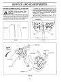
TINE REPLACEMENT
(See Figs. 24, 25 and 26)
gloves or other protection when hanCAUTION:
dling tines. Tines are sharp- Wear
! _
,
To maintain the superb -tilling performance of this
machine the tines should be checked for sharpness,
wear, and bending, particularly the tines which are next
to the transmission.
If the gap between the tines
exceeds 3-1/2 inches they should be replaced or
straightened as necessary.
=
New tines should be assembled as shown in Fig. 26.
Sharpened tine edges will rotate rearward from above.
I
I!
== .H H.,.=.....=..HI
A badly worn tine causes your tiller to work harder and dig
more shallow° Most important, worn tines cannot chop and
shred organic matter as effectively nor bury it as deeply as
good tines. A tine this worn needs to be replaced.
|f,
WORN TINE
NEW TINE
1
1
1
I
3-112"MAX _
FIG. 25
FIG, 24
HAIRPIN CLIP
COUNTER
TINE
ROTATION
HAIRPIN
CLIP
SHARP EDGE
SHARP EDGE
/
SHARP
EDGES
SHEAR PIN
SHEAR PIN
FIG. 26
17
,,H
!=l= ==
SERVmCE AND ADJUSTMENTS
ENGINE
TO ADJUST
(See Fig, 27)
FINAL SETTING
THRO'N'LE
CONTROL
CABLE
o
Loosen cable clamp screw to allow cable to move_
o
Move throttle control lever on upper' handle to "FAST"
position,,
Pull throttle cable out to end of travel
o
,
-
Start engine and allow to warm for five minutes_ Make
final adjustments with engine running at idle and drive
control bar in "DISENGAGED" position.
=
With throttle control lever in "SLOW" position, turn idle
needle valve in (clockwise) until engine begins to die
then turn out (counterclockwise)
until engine runs
rough. Turn valve to a point midway between those two
positions.
IDLE RPM ADJUSTMENT
Hold cable in this position and tighten clamp screw
securely.,
-
THROTTLE
CABLE
To adjust idle RPM, rotate throttle linkage counterclockwise and hold against stop while adjusting idle
speed adjusting screw to obtain 1750 RPM.. Release
throttle linkage.
ACCELERATION
=
High speed stop is factory adjusted. Do not adjust or
damage may result..
IMPORTANT:
NEVER TAMPER WITH THE ENGINE
GOVERNOR, WHICH IS FACTORY SET FOR PROPER
ENGINE SPEED OVERSPEEDINGTHEENGINEABOVE
THE FACTORY
HIGH SPEED SETTING
CAN BE
DANGEROUS. IF YOU THINK THE ENGINE-GOVERNED
HIGH SPEED NEEDS ADJUSTING, CONTACT YOUR
NEAREST
AUTHORIZED
SERVICE
CENTER/
DEPARTMENT, WHICH HAS THE PROPER EQUIPMENT
AND EXPERIENCE
TO MAKE ANY NECESSARY
ADJUSTMENTS.
CLAMP SCREW
FIG. 27
TO ADJUST
CARBURETOR
TEST
Move throttle control lever from "SLOW" to "FAST"
position. If engine hesitates or' dies, turn needle valve
out (counterclockwise)
1/8 turn
Repeat test and
continue to adjust, if necessary, until engine accelerates smoothly..
(See Fig. 28)
The carburetor has a high speed jet and has been preset at
the factory and adjustment should not be necessary. However, minor adjustments may be required to compensate
for differences in fuel, temperature, altitude or load_ If the
carburetor does need adjustment, proceed as follows.
THROTTLELINKAGE
In general, turning the idle needle valve in (clockwise)
decreases the supply of fuel to the engine giving a leaner
fuel!air mixture. Turning the needle valve out (counterclockwise) increases the supply of fuel to the engine giving
a richer fuel/air mixture.
IMPORTANT:
DAMAGE
SEATS IN CARBURETOR
TURNED IN TOO TIGHT.
PRELIMINARY
SETTING
,
Air cleaner assembly must be assembled to the carburetor when making carburetor adjustments.
•
Be sure the throttle control cable is adjusted properly
(see above).
',
IDLE SPEED
ADJUSTING SCREW
TO THE NEEDLES
AND THE
MAY RESULT IF SCREWS ARE
\
IDLE NEEDLE VALVE
FIG. 28
With engine off, turn idle needle valve in (clockwise)
closing it finger' tight and then turn valve out (counterclockwise) 1-1/2 turns_
18
ENGINE
Immediately prepare your tiller for storage at the end of the
season or if the unit will not be used for 30 days or more.
= Hn=,=
n,i,u
CAUTION:
=
OIL
Drain oil (with engine warm) and replace with clean oil.
(See "ENGINE" in the Customer Responsibilities section of
this manual).
..................
H
Never store the tiller with
where
fumes
may
reach
an open
flame
gasoline
in the
tank
inside
a building
or spark. Allow the engine to cool
before storing in any enclosure.
CYLINDERS
o
Remove spark plug_
•
Pour I ounce (29 ml) of oil through spark plug hole into
cylinder.
TILLER
•
Pull starter handle slowly several times to distribute oil.
•
Clean entire tiller (See "CLEANING" in the Customer
Responsibilities section of this manual).
°
Replace with new spark plug,,
o
Inspect and replace belts, if necessary (See belt replacement instructions in the Service and Adjustments
section of this manual)_
OTHER
o
Do not store gasoline from one season to another_
o
Lubricate as shown in the Customer Responsibilities
section of this manual.
•
Replace your gasoline can if your can starts to rusL
Rust and/or dirt in your gasoline will cause problem&
•
Be sure that all nuts, bolts and screws are securely
fastened° Inspect moving parts fordamage, breakage
and wear. Replace if necessary°
o
If possible, store your unit indoors and cover it to give
protection from dust and dirt.
..............
o
=
i
IH=,,=
=
.
Cover your unit with a suitable protective cover that
does not retain moisture, Do not use plastic, Plastic
cannot breathe which allows condensation to form and
will cause your unit to rust.
IMPORTANT:
NEVER COVER TILLER WHILE ENGINE
AND EXHAUST AREAS ARE STILL WARM
Touch up all rusted or chipped paint surfaces; sand
iightly before painting.
ENGINE
FUEL SYSTEM
IMPORTANT:
tT IS IMPORTANT TO PREVENT GUM
DEPOSITS FROM FORMING {N ESSENTIAL FUEL
SYSTEM PARTS SUCH AS THE CARBURETOR, FUEL
FILTER, FUEL HOSE, OR TANK DURING STORAGE,
ALSO, EXPERIENCE
INDICATES
THAT ALCOHOL
BLENDED FUELS (CALLED GASOHOL OR US[NG
ETHANOL OR METHANOL) CAN ATTRACT MOISTURE
WHICH LEADS TO SEPARATION AND FORMATION OF
ACIDS DURING STORAGE. ACIDIC GAS CAN DAMAGE
THE FUEL SYSTEM OF AN ENGINE WHILE IN STORAGE°
°
Drain the fuel tank_
o
Start the engine and let it run until the fuel lines and
carburetor are empty.
o
Never use engine or carbu retor cleaner products in the
fuel tank or permanent damage may occur.
Use fresh fuel next season
•
NOTE:
Fuel stabilizer is an acceptable alternative in
minimizing the formation of fuel gum deposits during storage. Add stabilizer to gasoline in fuel tank or storage
container. Always toIlow the mix ratio found on stabilizer
container. Run engine at least 10 minutes after adding
stabilizer to allow the stabilizer to reach the carburetor. Do
not drain the gas tank and carburetor if using fuel stabilizer.
19
,Hmn
......................
n,H, M m,_,,
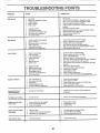
TROU
n nm,
LESHOOTING
,n,, M
, = u, =urn=
Out of fuel
2
3
4
5
Engine not "CHOKED"
Engine flooded
Dirty air cleaner
Water #1fuel
properly,
Clogged fuel tank
Loose spark plug wire
Bad spark plug or improper gap
Carburetor out of adjustment
Oil soaked air filter
=,m= =,u
!Hu
Hard to start
= mu
u,-,
,n ,nil,
1.
6
7
8
9.
10.
n nn'=',',,'
CORRECTION
== m
Will not start
POUNTS
n != n mm
CAUSE
PROBLEM
==-n,!
= ,,,H,=,,,,
Fill fuel tank,.
See "TO START ENGINE" in Operation section
Wait several minutes before attempting to start
4
5
Clean or reptace air cleaner cartridge.
Drain fuel tank and carburetor, and refill tank with fresh
6
7,
gasoline
Remove fuel tar_k and clean
Make sure spark plug wire is seated propedy on plug,
8
9
10
Replace spark plug or adjust gap
Make necessary adjustments
Replace air filter
=HUn
1, m,H
1.
2
3
4
5,,
&
Throttle control not set properly
Dirty air cleaner,
Bad spark plug orimproper gap
State or dirty fuel
Loose spark plug wire
Carburetor out of adjustment
1
2,,
3
4
5
6
Place throttle control in "FAST" position
Clean or replace air cleaner cartridge.
Replace spark plug or adjust gap
Drain fuel tank and refilJ with fresh gasoline,
Make sure spark plug wire is seated properly on plug
Make necessary adjustments.
1
2
3
4
5
6
7
Engine is overloaded
Dirty air cleaner
Low oil fevet/dirty oil
Faulty spark plug
Oil in fuel,
Stale ordirty fuet
Water in rue[
1
2
3
4,
5
6
7
Set depth stake for shallower tilling
Clean or replace air cleaner cartridge
Check oil level/change oil,
Clean and regap or change spark plug
Drain and clean fuel tank and refill, and clean carburetor
Drain fuel tank and relil! with fresh gasoline
Drain fuel tank and carburetor, and refitl tank with fresh
Clogged fuel tank
Spark plug wire loose
Dirty engine air screen
Dirty/clogged muffler
Carburetor out of adjustment
Poor compression,
8
gasotine
Remove fueltank and clean
8
9
10
11
12
13
9
10
11
12
13
Connect and tighten spark pfug wire,
Clean engine air screen
Clean/replace muffler,
Make necessary adjustments
Contact an authorized service center/department
=,u
1
2_
3
4
5
Engine overheats
,=
!,,
2,
3
Low oil level!dirty oil
Dirty engine air screen
Dirty engine,
Partially plugged muffler
lmpropercarburetor adjustment,
=
= H,,,,,=,
1,
2
3
4
Check oil level/change oil
C!ean engine air screen
Clean cylinder fins, air screen, and muffler area,
Remove and clean muffler_
5,
Adjust carburetor
to richer posLtion
..................
Excessive bounce/
difficult handling
n muu
Soil balls up or clumps
=nmmm
1
11 111,
H, n n,,,,
=Hnnnn,,,,,,
Wait for more favorable
Ground too wet,
,111,1
nHm,
t
2
3
Engine runs but tiller
won't move
t
2
3
Drive control bar is not engaged
V-belt not correctly adjusted
V-belt is off puIfey(s),
soil conditions,
=11,11111,111
Engage drive control
Inspecb'adjust V-belt
Inspect V-belt
= n mn
Engine runs but labors
when tilling
1.
2
3
Tiiling too deep
Throtttecontrol
not property adjusted.
Carburetor out of adjustment,
1,
Shear pin(s) broken,
1.
2
3
Replace shear pin(s).
= 11, ,11,
2O
n=r,,,rn,
Set depth stake for shallower tilling
Check throttle control setting
Make necessary adjustments
n Hm,
Tines will not rotate
n,n,n,,
Moisten ground or wait for more favorabJe soil
conditions
Ground too dr,] and hard
i= Hm==
= n ran,