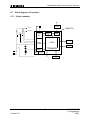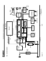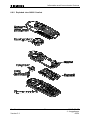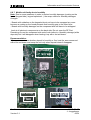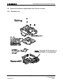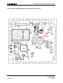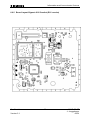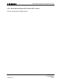
1
Information and Communication Products
Service Manual
Gigaset 4010/ 15 Classic base station,
Gigaset 4010/ 15 Comfort base station
Gigaset 4000 Classic handset,
Gigaset 4000 Comfort handset
Level 2.5
Confidential
Version 2.1
1
ICM D CC ST
J. Junggebauer
05/01
Information and Communication Products
1 Table of contents
1
TABLE OF CONTENTS .............................................................................................................................2
2
ADDITIONAL FEATURES AND DIFFERENCES TO GIGASET 3000 ..............................................3
2.1
3
DECT-SPECIFIC DETAILS ............................................................................................................................3
PROCEDURES ............................................................................................................................................4
3.1
3.2
3.3
SERVICE PROCEDURES FOR GIGASET 4000 CLASSIC ...................................................................................4
SERVICE PROCEDURES FOR GIGASET 4000 COMFORT .................................................................................5
SERVICE PROCEDURES FOR GIGASET 4010/ 15 CLASSIC/ COMFORT BASE STATION ....................................6
4
INFO STICKER/ LASERED IMPRINT AND STICKER ON MICROPROCESSOR ........................6
5
FAULT CODES............................................................................................................................................6
6
FAULT DIAGNOSIS AND ELIMINATION ............................................................................................6
6.1 FUNCTIONAL TEST......................................................................................................................................6
6.2 RECOGNITION OF TYPICAL CUSTOMER PROBLEMS ......................................................................................6
6.3 CHECK OF COMPLETE SYSTEM WITH FAULT DESCRIPTION OF CUSTOMER ....................................................6
6.4 CHECK OF COMPLETE SYSTEM WITHOUT FAULT DESCRIPTION OF CUSTOMER..............................................6
6.5 CHECK OF COMPONENT WITH FAULT DESCRIPTION OF CUSTOMER ..............................................................6
6.6 CHECK OF COMPONENT WITHOUT FAULT DESCRIPTION OF CUSTOMER ........................................................6
6.7 BLOCK DIAGRAMS OF HANDSETS ................................................................................................................6
6.7.1
Classic handset ................................................................................................................................6
Comfort handset .............................................................................................................................................6
6.8 REPAIR OF MOBILE UNIT GIGASET 4000 CLASSIC AND COMFORT ...............................................................6
6.8.1
Exploded view G4000 Classic..........................................................................................................6
6.8.2
Exploded view G4000 Comfort ........................................................................................................6
6.8.3
Disassembling ..................................................................................................................................6
6.8.4
Assembling .......................................................................................................................................6
Board Layout Gigaset 4000 Classic...............................................................................................................6
6.8.6
Board Layout Gigaset 4000 Comfort...............................................................................................6
6.8.7
Mobile unit faulty due to humidity ...................................................................................................6
6.8.8
SLR (microphone-path faulty)..........................................................................................................6
6.8.9
RLR (earphone-path faulty) .............................................................................................................6
6.9 REPAIR OF BASESTATION GIGASET 4010/ 4015 CLASSIC/ COMFORT ..........................................................6
6.9.1
Exploded view ..................................................................................................................................6
6.9.2
Disassembling ..................................................................................................................................6
6.9.3
Assembling .......................................................................................................................................6
6.9.4
Board Layout Gigaset 4010 Classic (EU1 version).........................................................................6
6.9.5
Board Layout Gigaset 4010 Comfort (EU1 version) .......................................................................6
6.9.6
Board layout Gigaset 4015 Classic (EU1 version) ..........................................................................6
6.9.7
Board layout Gigaset 4015 Comfort (EU1 version) ........................................................................6
6.9.8
Charging problems ..........................................................................................................................6
6.9.9
Base station faulty due to lightning stroke .......................................................................................6
Confidential
Version 2.1
2
ICM D CC ST
J. Junggebauer
05/01
Information and Communication Products
2 Additional features and differences to Gigaset 3000
4000 Classic:
- Improved standby time up to 200 h (NiCd)
- Alphanumeric display (12 digits plus 2 lines for pictograms)
- Handset operation controlled via menu
- Date and time functions with protection against power failure
- Alarm call/ date reminder on display
- LED on top of the handset signalling MWI and incoming calls
- Directory with memory for 20 names plus numbers
4000 Comfort:
- Improved standby/ use time up to 350/ 23 h (NiMH: 1600 mAh)
- Large graphical display with 5 lines x 16 characters (101 x 61 pixel)
- Navigation key
- Tel.book for max. 200 entries
- Date and time functions with protection against power failure
- Alarm call/ date reminder on display
- LED on top of the handset signalling MWI and incoming calls
- Walky-Talky mode with second 4000 Comfort handset
- Handling of AM via handset like a mobile phone (4015 base station necessary)
- 14 display languages
4010/ 15 Base stations:
- 4 different base stations (4010/15 Classic and 4010/15 Comfort)
- New features/ differences on Comfort base station: - Transmission of texts (SMS)
- 4015: Voice dialling
of 20 names + 3 commands
- 4010/15: no ringer
- 4015: no loudspeaker
No more PIN-Code for handsets existing.
A difference to G3000 systems is that the handset has to be registered to the base
station by the customer. Therefore the customer has to insert the handset in the base
station and wait until the handset is regsitered. A handset that has been registered on
another base station has to be registered manually (similar to G3000).
Therefore a paging key is existing under the base station.
2.1 DECT-specific details
Number of channels:
120
Radio frequency range: 1880 MHz to 1900 MHz (altered for certain countries)
Duplex method:
Time-division multiplexing, 10 ms frame length
Channel grid:
1728 kHz
Bit rate:
1152 kBit/s
Modulation:
GFSK
Voice coding:
ADPCM (32 kBit/s)
Confidential
Version 2.1
3
ICM D CC ST
J. Junggebauer
05/01
Information and Communication Products
3 Procedures
This chapter shows the hidden service procedures for Gigaset 4000 Classic, 4000
Comfort and 4010 base stations.
Note: The service procedures are confidential.
3.1
Service procedures for Gigaset 4000 Classic
Reset to factory defaults (customer procedure):
This procedure resets the handset to factory defaults.
Press softkey "menu", 9 3 and confirm with o.k. (see user guide).
Displaytest:
Press 1, 4 and 7 simultaneously and hold down while you switch on.
Press any key to toggle between the displayed signs. Afterwards switch handset off.
To get into the service procedures you need to press 1,4 and 7 simultaneous
and hold down while you switch on, afterwards press 76200.
1. SW-Version and IPUI:
On the left upper corner the number of the menu is shown (here menu 1).
At first the SW-version is displayed. The digits above the 2. arrow show the version
(e.g. 16).
When scrolling down with the "arrow down key" the IPUI number is displayed.
The I on the left side indicates that this is the IPUI.
2. QS data:
This data is only important for the production, not for service purposes.
3. Speechpath-test:
You can select this item when you want to check the speechpath by blowing into the
microphone and checking this noise on the earphone (without beeing registered to a
base station).
Confidential
Version 2.1
4
ICM D CC ST
J. Junggebauer
05/01
Information and Communication Products
3.2
Service procedures for Gigaset 4000 Comfort
Displaytest, Software-Version & IPUI, Speechpath test and Metering mode:
press 1, 4 and 7 simultaneously
and keep pressed
switch on and keep pressed until display testpattern is visible, then release all
keys
press 76200
SW-Version, IPUI Speechpath test
Read out software version
and the IPUI number
Switch a direct loop from
microphone to earphone
(check the path by blowing
into the microphone).
Metering mode
Press “o.k.” to tick it and
press menu key to switch
off the handset. Now you
can see radio parameters
during normal usage
*** example:
98 - 9 - 04 - 096 -
RX - Level
Frequency (0...9)
Time slot (0...11)
Base station code
bit error rate
100 = 100% o. k.
The items QS-Data,Batt mode and DSP parameters have been implemented for
development and production purposes and are not needed in service.
Confidential
Version 2.1
5
ICM D CC ST
J. Junggebauer
05/01
Information and Communication Products
3.3
Service procedures for Gigaset 4010/ 15 Classic/ Comfort base station
Note: For parameters X, Y, option see table below.
Press: "menu-key", 8, 9, X, 76200 (only if X=3 or 4), Y, select option, o.k.
A pos. acknowledge (rising sequence of notes) indicates that the procedure has been
accepted.
Feature
Pause after signal-key
Automatic attenuation correction
(dependant on country)
Time for end of call identification
(to distinguish between 2 ringing pulses of
one call with long pauses between pulses
and 2 separate calls)
Hook-flash-prevention (cradle switch
identification) (short press on cradle switchkey is extended by SW to prevent that it is
interpreted as a press on the flash-key)
Pause after line seizure
X 76200 Y
Option
1
2 1 = 800 ms
2 = 1600 ms
3 = 3200 ms
1
3 0 = off
1 = on
1
4 0 = 4 sec.
1 = 5.5 sec.
2 = 7 sec.
3 = 11 sec.
1
5 0 = 800 ms
1 = 2000 ms
1
-
System PIN reset
Programming data on an address
Read out SW-version
3 76200
4 76200
4 76200
Range of ringing frequency recognition
4
76200
Dial pulsing: pulse pause ratio
4
76200
CLIP activation
Off-hook CLIP activation
Approval test
4
4
6
76200
76200
76200
Confidential
Version 2.1
6
6 1 = 1 sec.
2 = 3 sec.
3 = 7 sec.
4 = 2.5 sec.
1 Specific code needed
2 Example: 01002_…..
01 = SW-variant
002 = SW-version
3 0 = 23- 54 Hz
1 = 20- 60 Hz
2 = 15-75 Hz
4 0 = 1.5 : 1
1= 2 :1
5 Select 0 (on) or 1 (off)
6 Select 0 (on) or 1 (off)
6
-
ICM D CC ST
J. Junggebauer
05/01
Information and Communication Products
only Gigaset 4015 Classic/ Comfort:
Feature
Select speech 1 for AM phrases (tones)
Select speech 2 for AM phrases
Select speech 3 for AM phrases
Select speech 4 for AM phrases
Confidential
Version 2.1
X 76200 Y
2
1
2
2
2
3
2
4
7
Option
-
ICM D CC ST
J. Junggebauer
05/01
Information and Communication Products
4 Info sticker/ lasered imprint and sticker on microprocessor
S30852-S1401-A154
...............
CT/N5
These are the 2 important numbers on the info sticker.
The first number shows the type of the phone.
Example:
- S30 means new component
S36 means swap component
- 852 means Gigaset family
- S14xx means 4000 family
- The following 2 characters indicate the country.
B1 means Germany (Siemens); A1 means Germany (PTT)
C1 Austria
C4 Australia
.....
- The following character shows you the variant.
Euro-PTT-Version, Base with Classic-/ Comfort handset...
- The last character indicates the colour.
The second number indicates the date of production.
CT stands for Bocholt.
The next character shows the year of production.
N = 2001
The last character shows the month of production.
1-9 = January to September
O = October
N = November
D = December
Sticker on Microprocessor:
Date: March,11,2001
N311
T
I
M
E
L
I
N
E
S
T
A
T
E
Partnumber of board
Confidential
Version 2.1
8
ICM D CC ST
J. Junggebauer
05/01
Information and Communication Products
5 Fault codes
Code
D1
D2
D3
D4
D7
D9
D 11
D 12
D 13
D 14
D 15
D 16
D 18
D 19
D 20
D 25
D 26
D 28
D44
A04
A27
Symptom
No key function
No ringing function
Charging problems
Display problems
Breaking off calls
Poor call quality (humming, noises)
No outgoing call possible
No registration/ no call setup
Answering machine problems
Problems with use of „hands-free“
Range too short
Mechanical fault
Miscellaneous
SLR (microphone-path faulty)
RLR (earpiece-path faulty)
No failure found
No function
Diverse procedures programmed wrong
AC-Adapter faulty
Stand-by time/ battery problems
Keypad faulty
Confidential
Version 2.1
9
N 10
N 11
N12
N 13
N 17
N 34
N 37
N 38
N 39
Cause
Not soldered
Cold soldered
Electric fault
Mechanic fault
Missing component
Dirty component
Loose component
Humidity damage
Lightning stroke damage
ICM D CC ST
J. Junggebauer
05/01
Information and Communication Products
6 Fault diagnosis and elimination
There are different faults that could appear.
Not all incoming components or systems have to be faulty.
The customer could have problems with the operation of the phone or
could have placed it close to a device (PC...) that affects it.
So you won’t identify a fault.
It could also happen, that there is a loose connection in the phone
(due to a cold soldering joint or something else).
So the fault won’t appear each time you test the phone.
There are different possibilities to test a phone depending on the information
you received with the phone.
6.1
Functional Test
There is an incoming and an outgoing test.
The difference between them is that in the outgoing test you make a reset
on the component after testing in case of swap (to deregister, reset PIN and
set to factory defaults).
Outgoing test (system):
1)
Displaytest 4000 Classic:
Mobile unit is switched off.
Press 1, 4 and 7 simultaneous and hold down while switching on.
Press any key to alter pattern.
2)
Charging-test:
Mobile unit is switched off.
Put mobile unit into charging cradle.
One segment of the battery display has to start blinking automatically
when putting in.
3)
There are 2 possibilities of testing the fundamental functions of the telephone:
1) Test with PBX (private branch exchange):
a) Ringer test (not for Comfort base stations)
b) Dialling test
c) Audible test of telephone in transmit and receive direction (speech)
with the help of a second phone connected to the PBX.
Confidential
Version 2.1
10
ICM D CC ST
J. Junggebauer
05/01
Information and Communication Products
2)
-
Test with telephone tester, if existing (e.g. WPG 1000):
Ringer test (not for Comfort base stations)
DC resistance and isolation resistance (only for base station test)
Testing the dial information (only for base station test)
Testing the flash hookswitch (signal key) (only for base station test)
Audible test of telephone in transmit direction (SLR)
Audible test of telephone in receive direction (RLR)
4)
Make a fundamental reset on the base station you want to test in case of swap:
Disconnect mains.
Press paging key under the base station and hold down.
Plug in AC- adapter.
Hold key pressed for 25 seconds. Release paging key.
The base station is now set to factory defaults.
The system code is set to 0000 and all mobile units are deregistered.
5)
Reset handset to factory defaults in case of swap:
Incoming test:
Confidential
Version 2.1
only step 1 to 3
11
ICM D CC ST
J. Junggebauer
05/01
Information and Communication Products
6.2
Recognition of typical customer problems
This chapter shows the incoming department which fault code refers to which
problem and which component is faulty.
Some problems concerning the mobile unit (not possible to switch on; not possible to
register; acoustic problems; charging problems ...) could be caused by humidity.
So you will have to open the mobile unit (opening tool) and look for tracks of a
humidity damage.
Many problems concerning the base station could be caused by lightning stroke.
So you will have to open the base station and look for tracks of a lightning stroke.
Problem 1:
The customer can‘t hear the other subscriber during a call
(or hears his speach at a low volume).
When he blows into the microphone he can‘t hear his noises on the earpiece.
Fault code: D 20 (RLR)
Faulty component: Mobile unit
When he blows into the microphone he can hear his noises on the earpiece.
Fault code: D 20 (RLR)
Faulty component: Base station
Problem 2:
Other subscribers can‘t hear the customer during a call
(or hear his speach at a low volume).
When he blows into the microphone he can‘t hear his noises on the earpiece.
Fault code: D 19 (SLR)
Faulty component: Mobile unit
When he blows into the microphone he can hear his noises on the earpiece.
Fault code: D 19 (SLR)
Faulty component: Base station
Problem 3:
The customer can‘t switch on his mobile unit.
Æ Check the batteries and insert new ones for testing.
Fault code: D 26 (no function)
Faulty component: Mobile unit
Confidential
Version 2.1
12
ICM D CC ST
J. Junggebauer
05/01
Information and Communication Products
Problem 4:
The customer can’t call or/ and can’t be called (no ringing).
His mobile unit seems to work properly.
Æ Check the AC-adapter first.
Fault code: D 1 (no key function), D44 (AC-Adapter faulty)
or D 11 (if only no outgoing call possible and AC-Adapter ok)
Faulty component: AC-adapter or base station
Problem 5:
The segment of the battery display doesn’t start blinking when charging.
Æ Check the batteries and insert new ones for testing.
Æ Check the charging cradle (golden device).
Fault code: D 3 (charging problems (if batteries are o.k.))
Faulty component: batteries or mobile unit or base station/ charging cradle
Problem 6:
The mobile unit or the base station doesn’t ring.
Æ Check AC-adapter (if base station) or batteries and insert new ones for testing.
The 4010/15 Comfort base station doesn't have a ringer.
Classic base station must ring.
Fault code: D 2 (no ringing function)
Faulty component: Mobile unit or base staion
Problem 7:
Some characters are not visible or only sometimes visible.
Fault code: D 4 (Display problems)
Faulty component: Mobile unit
Problem 8:
The customer has caused visible mechanical damages.
Fault code: D 16
Faulty component: Mobile unit or base station
Confidential
Version 2.1
13
ICM D CC ST
J. Junggebauer
05/01
Information and Communication Products
Problem 9:
There can be various possibilties.
Example: The client claims that he can’t set up an outgoing call or the ringing volume
is too low. Check the programmed procedures (see chapter Procedures).
Fault code: D 28 (diverse procedures programmed wrong)
Faulty component: Mobile unit or base station
Problem 10:
The customer claims that the connection breaks off if he tries to go away from the
base station. Inside buildings the range should be up to 50 m, but if there are
ferroconcrete-walls between mobile unit and base station the radio contact can break
off due to absorbtion and reflections at the wall.
Test the range by picking up the handset and going away from the base
station for the desired distance (no walls between).
If there is still a problem check which component is faulty by using a golden device.
Note that 50 m is the maximum range inside buildings. Depending on the design of
the device and how the customer holds it (hand close to antenna and between base
station and antenna decreases range) the range could decrease. The different
Gigaset models have slightly different ranges (best range has the Pocket handset).
Fault code: D 15 (Range too short)
Faulty component: Mobile unit or base station
Problem 11:
The connection breaks off sometimes during a call.
Æ Check the batteries and insert new ones for testing.
If they are o.k. and there is still a problem use a golden device to find out which
component is faulty.
Fault code: D 7 (Breaking off calls)
Faulty component: Mobile unit or base station
Problem 12:
The customer claims that there is a poor call quality or that there are noises audible
during a call (humming...). The noises could also be audible on the earphone of the
other subscriber when problems in transmit direction. Check the call quality.
If the customer was right take a golden device to identify the faulty component.
Fault code: D 9 (Poor call quality (hummung, noises))
Faulty component: Mobile unit or base station
Confidential
Version 2.1
14
ICM D CC ST
J. Junggebauer
05/01
Information and Communication Products
Problem 13:
The customer claims that his mobile unit doesn’t ring (incoming call) or he claims that
he can’t set up an outgoing call.
The mobile unit doesn’t ring when pressing the paging key.
The display-sign referring to the radio connection is blinking.
Æ 4000 Comfort: Press menu and select "handset settings", then choose "select
.base". If there is no tick on any base station the handset is not registered.
Æ The mobile unit has no connection or has lost the connection to the base station.
Try to register the mobile unit to the base station.
Problem 14:
The customer claims that there is no function when pressing any key.
There could also be problems when pressing some keys.
Fault code: D 1 (No key function)
Faulty component: Mobile unit
Confidential
Version 2.1
15
ICM D CC ST
J. Junggebauer
05/01
Information and Communication Products
6.3
Check of complete system with fault description of customer
Try to reconstruct the fault using the description of the customer.
Check the batteries and the AC-adapter.
Find out whether the customer has programmed something wrong
by checking the procedures concerned.
If that was not successful make an incoming test.
If there is a fault try to find out which component is faulty by registering on a
golden device and testing again (deregister it from the golden device after testing).
Register swap component to customer component.
6.4
Check of complete system without fault description of customer
Check the batteries and the AC-adapter if existing.
Make an incoming test.
If there is a fault try to find out which component is faulty by registering at a
golden device and testing again (deregister it from the golden device after testing).
Register swap component to customer component.
6.5
Check of component with fault description of customer
Register component to golden device.
Try to reconstruct the fault using the description of the customer.
Check the batteries (handset) or the AC-adapter (base station).
Find out whether the customer has programmed something wrong
by checking the procedures concerned.
If that was not successful make an incoming test.
Deregister customer device from golden device after testing.
6.6
Check of component without fault description of customer
Register component to golden device.
Check the batteries (handset) or the AC-adapter (base station).
Make an incoming test.
Deregister customer device from golden device after testing.
Confidential
Version 2.1
16
ICM D CC ST
J. Junggebauer
05/01
Information and Communication Products
6.7
Block diagrams of handsets
6.7.1 Classic handset
RF-part
+3,6V
PMB7720
+2.65V
Analogue
Front
End
BMC
DSP
MCU
PowerControl
Display
Keypad
Peripherals
ADC
Temp
Charger switch
Confidential
Version 2.1
E²PROM
17
ICM D CC ST
J. Junggebauer
05/01
Version 2.1
ESD
Filter
Battery
Charger
switch
6.7.2 Comfort handset
Confidential
IAkku
3..5V
2.5V
4.0V
VDCDC
3.5V
PowerControl
BMC
On/ off-key
VBAT (3.6V max)
Analogue
Front-End
VDD 2.5V
05/01
18
Keypad
Handsfree-LED
384K ROM
Microprocessor
E2PROM 4K
Temp.
Sensor
6K RAM
DSP +Handsfree
SC 14406
RF-part
Antenna
Information and Communication Products
Inverting
Switch
ICM D CC ST
J. Junggebauer
Display illumination
LCD-Module
Adjustment
Network
LM 4871
4.0V
VDCDC
Headset
Interface
MWI
-LED
Information and Communication Products
6.8
Repair of mobile unit Gigaset 4000 Classic and Comfort
Special equipment (same tools as for G2000 & G3000):
Opening-tool G2000 (left), G3000 (modified pliers) and Battery-dummy G3000:
Confidential
Version 2.1
19
ICM D CC ST
J. Junggebauer
05/01
Information and Communication Products
6.8.1 Exploded view G4000 Classic
Confidential
Version 2.1
20
ICM D CC ST
J. Junggebauer
05/01
Information and Communication Products
6.8.2 Exploded view G4000 Comfort
Confidential
Version 2.1
21
ICM D CC ST
J. Junggebauer
05/01
Information and Communication Products
6.8.3 Disassembling
ESD regulations have to be followed !
6.8.3.1 First alternative (valid for both handsets)
First and recommended opening procedure (fast; housing will be destroyed):
Needed material: Opening-tool Gigaset 3000 and battery dummy Gigaset 3000
Insert pliers in belt-clip-hole and press to open upper part of the housing.
Do the same in the other belt-clip-hole.
Insert pliers in charging-contact-hole and press to open lower part of the housing.
If necessary do the same in the other charging-contact-hole.
Confidential
Version 2.1
22
ICM D CC ST
J. Junggebauer
05/01
Information and Communication Products
Insert battery dummy G3000 in battery compartment.
Pull the board evenly in order to get upper and lower spring at the same time out of
the battery compartment.
The loudspeaker of the Comfort handset can be reused when using new case shells.
Just remove snap hooks (red circles) with a sidecutter and lift loudspeaker.
Confidential
Version 2.1
23
ICM D CC ST
J. Junggebauer
05/01
Information and Communication Products
6.8.3.2 Second alternative (Comfort handset)
Second alternative with G2000 opening tool (slow, but housing could possibly be
reused (not for swap); please check hooks on the housing carefully after opening).
The location of the hooks compared to Classic is different (especially belt clip hook).
Insert opening tool G2000 in the above described position between both hooks (red
rectangles). After inserting push the tip of the tool downwards (red arrow) and press
the other end down (green arrow) in order to lift the upper case shell. If necessary
insert a second opening tool G2000 in the hook area (red rectangles) and try so to lift
the upper case shell.
Do the same on the opposite side of the handset.
Insert the tool in the above described position and try to disengage the belt clip hook.
Do the same on the opposite side of the handset.
Confidential
Version 2.1
24
ICM D CC ST
J. Junggebauer
05/01
Information and Communication Products
Pull on both case shells in order to open the handset.
Insert battery dummy G3000 in battery compartment.
Pull the board evenly in order to get upper and lower spring at the same time out of
the battery compartment.
Confidential
Version 2.1
25
ICM D CC ST
J. Junggebauer
05/01
Information and Communication Products
6.8.3.3 Second alternative (Classic handset)
Second alternative with G2000 opening tool (slow, but housing could possibly be
reused (not for swap); please check hooks on the housing carefully after opening).
Insert opening tool G2000 in the above described position between both hooks (red
rectangles). After inserting push the tip of the tool downwards (red arrow) and press
the other end down (green arrow) in order to lift the upper case shell. If necessary
insert a second opening tool G2000 in the hook area (red rectangles) and try so to lift
the upper case shell.
Do the same on the opposite side of the handset.
Insert the tool in the
above described position
and try to disengage the
belt clip hook (red circle)
by pressing it downwards.
Do the same on the
opposite side of the
handset.
Confidential
Version 2.1
26
ICM D CC ST
J. Junggebauer
05/01
Information and Communication Products
Pull on both case shells in order to open the handset.
Insert battery dummy G3000 in battery compartment.
Pull the board evenly in order to get upper and lower spring at the same time out of
the battery compartment.
Confidential
Version 2.1
27
ICM D CC ST
J. Junggebauer
05/01
Information and Communication Products
6.8.3.4 Replacement of display covers
1. Classic display:
Snap the 2 hooks on the bottom open (1).
Then lift the display carefully until the 2 snap
hooks on the top open (2).
2
1
To reassemble the display you just need to press
the new cover gently on its place.
2. Comfort display:
Insert the opening tool G2000 between both plastic parts (cover and bottom) and
press down in order to open the first hook (red rectangle).
Do the same on the other side.
Insert the tool on one of the sides (red arrow) between both plastic parts and press
down to open the other hooks (red circle).
To reassemble the display you just need to press the new cover gently on its place
so that all 4 hooks engage.
Confidential
Version 2.1
28
ICM D CC ST
J. Junggebauer
05/01
Information and Communication Products
6.8.4 Assembling
ESD regulations have to be followed !
Needed material: none
Use the exploded view as a help to see how and where the components are located.
Insert keypad, earphone and light conductor in upper case shell.
Insert board in upper case shell (note that earphone and keypad is fixed correctly).
If necessary fix the loudspeaker (only Comfort) in lower case shell.
Close handset with lower case shell by pressing both case shells together with your
hands.
Pay attention on the battery contact springs on board.
Make an optical inspection of the battery contact springs afterwards.
Put in batteries and check spring tension.
Switch the handset on to check correct function of battery contact springs.
Confidential
Version 2.1
29
ICM D CC ST
J. Junggebauer
05/01
Information and Communication Products
6.8.5 Board Layout Gigaset 4000 Classic
Confidential
Version 2.1
30
ICM D CC ST
J. Junggebauer
05/01
Information and Communication Products
6.8.6 Board Layout Gigaset 4000 Comfort
Confidential
Version 2.1
31
ICM D CC ST
J. Junggebauer
05/01
Information and Communication Products
6.8.7 Mobile unit faulty due to humidity
Note: Due to some measures in order to reduce humidity damages (coating on the
board (keypad side), keypad optimised...) the scrap criteria for humidity damages
changes.
- Boards with oxidation on the keypad side do not have to be scrapped any more
because a coating on the board prevents that humidity gets to the other layer.
- Boards with humidity damages on the component side still have to be scrapped.
Look at all electronic components on the back side. Do not open the RF-Part.
Remaining flux on the component side could look similar to a humidity damage (white
deposits) but it will disappear when heating it up with a hot air blower.
Recommendation:
When you are not sure whether deposit is humidity or flux, heat the area concerned
with a hot air blower and scrap the unit only when deposit doesn’t disappear.
Humidity
--> scrap
No scrap
No scrap
No scrap
Flux
Flux
Confidential
Version 2.1
32
ICM D CC ST
J. Junggebauer
05/01
Information and Communication Products
6.8.8 SLR (microphone-path faulty)
Fault code: D 19
Affected unit:
Gigaset 4000 Classic/ Comfort
Components:
Microphone
Needed equipment:
Soldering iron
Working material:
Desolder wick
Solder
Diagnosis:
The diaphragm of the microphone is affected by humidity or nicotine with increasing
age or the microphone could be electrically faulty. There will be a higher attenuation
when measuring SLR (sending loudness rating). In most cases the microphone is
defective.
Repair by component exchange:
Remove the microphone by desoldering the 2 solder joints.
You can also heat up both pins simultaneously with a broad soldering iron tip and
turn the board upside down, letting the microphone fall out.
Clean pads with desoldering wick and replace it by a new component afterwards.
Attention: Avoid excessive heat (2 seconds maximum)!
Test:
Put the repaired board in a testhousing.
Make a sidetone check by blowing into the microphone and checking the volume
of the noise on the earphone.
If there is a telephone tester with acoustic testhead make a SLR-test and check
whether the attenuation is o.k..
Confidential
Version 2.1
33
ICM D CC ST
J. Junggebauer
05/01
Information and Communication Products
6.8.9 RLR (earphone-path faulty)
Fault code: D 20
Affected unit:
Gigaset 4000 Classic/ Comfort
Components:
Earphone
Needed equipment:
Multimeter
Working material:
none
Diagnosis:
The diaphragm of the earphone could be affected by deposits with increasing age.
There will be a higher attenuation when measuring RLR (receiving loudness rating).
In most cases the earphone is defective.
If there is no noise audible on the earphone when making a sidetone check it’s also
possible that the wire of the coil is cut off.
Check the resistance of the coil with a multimeter.
If you measure a nearly infinitely high resistance, the wire may be cut off.
Repair by component exchange:
Use new earphone capsule.
Test:
Put the repaired board in a testhousing.
Make a sidetone check by blowing into the microphone and checking the volume
of the noise on the earphone.
If there is a telephone tester with acoustic testhead make a RLR-test and check
whether the attenuation is o.k..
Confidential
Version 2.1
34
ICM D CC ST
J. Junggebauer
05/01
Information and Communication Products
6.9
Repair of basestation Gigaset 4010/ 4015 Classic/ Comfort
6.9.1 Exploded view
Note: Gigaset 4015 Classic is
equipped with a loudspeaker
Confidential
Version 2.1
35
ICM D CC ST
J. Junggebauer
05/01
Information and Communication Products
6.9.2 Disassembling
ESD regulations have to be followed !
Needed material: suitable screw driver with cross recess
Unscrew the 5 screws on the lower case shell.
Lift lower case shell.
The loudspeaker of 4015 Classic is fixed with 2 snap hooks.
In order to get it out insert a screwdriver in the loudspeaker part of the hook and
press the plastic part of the base station to disengage the hook. Then lift the
loudspeaker and get with the screwdriver between both plastic parts of the other
hook and turn it to disengage the hook. Then take out the loudspeaker.
6.9.3 Assembling
ESD regulations have to be followed !
Needed material: suitable screw driver with cross recess
Put charger contact springs in upper case shell.
Insert board in upper case shell. Be careful with the antenna, because it could be
bent (or even the pad could be lifted) when it is pressed against the housing
Insert loudspeaker (only G4015 Classic).
Attach the other case shell and close the device by screwing the 5 screws in the
lower case shell.
Make sure that the charging contact springs are fixed correctly.
Confidential
Version 2.1
36
ICM D CC ST
J. Junggebauer
05/01
Information and Communication Products
6.9.4 Board Layout Gigaset 4010 Classic (EU1 version)
Buzzer
Confidential
Version 2.1
37
ICM D CC ST
J. Junggebauer
05/01
Information and Communication Products
6.9.5 Board Layout Gigaset 4010 Comfort (EU1 version)
Confidential
Version 2.1
38
ICM D CC ST
J. Junggebauer
05/01
Information and Communication Products
6.9.6 Board layout Gigaset 4015 Classic (EU1 version)
Not yet implemented in digital archive.
Confidential
Version 2.1
39
ICM D CC ST
J. Junggebauer
05/01
Information and Communication Products
6.9.7 Board layout Gigaset 4015 Comfort (EU1 version)
Not yet implemented in digital archive.
Confidential
Version 2.1
40
ICM D CC ST
J. Junggebauer
05/01
Information and Communication Products
6.9.8 Charging problems
Fault code: D 3
Affected unit:
Gigaset 4010/ 4015 Classic/ Comfort base station
Components:
charger contact springs
charging joints/ pads
Needed equipment:
Soldering iron
Glass fibre pen
Working material:
Desolder wick
Solder
Diagnosis:
The battery segment on the handset display doesn’t start blinking when charging.
Inspect the charging joints/ pads looking for small black holes on the surface.
Repair by cleaning/ soldering joint/ pad and component exchange:
Roughen the surface with a glass fibre pen.
Solder the charging joints so that there is a thin deposit of new solder on the joints.
Suck away surplus solder with desolder wick.
Roughen the surface with a glass fibre pen.
Use new contact springs.
Test:
Assemble the base station.
Check if battery segment on display starts blinking when charging.
Confidential
Version 2.1
41
ICM D CC ST
J. Junggebauer
05/01
Information and Communication Products
6.9.9 Base station faulty due to lightning stroke
The pictures are taken from a Gigaset 2010 base station.
Inspect the board with your eyes.
The components on the photos have been damaged by lightning stroke.
Confidential
Version 2.1
42
ICM D CC ST
J. Junggebauer
05/01