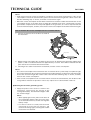
1
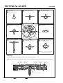
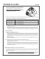
PARTS CATALOGUE / TECHNICAL GUIDE
Cal. 5J32A
PARTS CATALOGUE / TECHNICAL GUIDE (p. 1 – 22)
[SPECIFICATIONS]
Cal. No.
5J32A
Item
Movement
(x 1.0)
Movement
size
Outside diameter
ø26.4 mm
Casing diameter
ø25.6 mm
Height
4.15 mm
Time indication
3 hands Hour and minute hands move at 5-second intervals.
Second hand moves at 1-second intervals.
Driving system
• Step motor (Load compensated driving pulse type, 2 pieces)
Additional mechanism
•
•
•
•
•
•
•
•
•
•
Loss/gain
Monthly rate at normal temperature range: less than 15 seconds
Regulation system
Nil
Measuring gate by quartz tester
Use 10-second gate.
Power
supply
Power generator
Automatic generating system
Electricity Storage
Unit (E.S. Unit)
Titanium lithium ion rechargeable battery
(
)
Automatic generating system
Energy depletion forewarning function
Overcharge prevention function
Electronic circuit reset switch
Train wheel setting device
Date calendar
Instant setting device for date calendar
Automatic power save function
Manual power save function
Time relay function
Operating voltage range
0.45 V ~ 2.5 V
Duration of charge
Validity of time relay function : Approx. 4 years (Full charge)
Jewels
13 jewels
1
REMARKS ON REPAIRING CAL. 5J32A
Cal. 5J32A is an epoch-making model of SEIKO’s revolutionary KINETIC watches, just like 5J21A/5J22A. It
is equipped with innovative functions that have introduced a completely new concept into the KINETIC
technology SEIKO has cultivated in its long years of precision product manufacturing. In repairing Cal.
5J32A, therefore, you are requested to have the full knowledge of its functions and strictly observe the
repairing and checking instructions provided in this guide so that the watch will be repaired securely.
FEATURES OF CAL. 5J32A
Cal. 5J32A features the power save function that automatically stops the hands from moving if the watch is
left untouched for a certain period of time. When you decide to use it again, swinging the watch several times
will activate the time relay function, which starts the hands moving quickly to indicate the correct time and
resume the normal operation. In this way, Cal. 5J32A conserves the stored electrical energy by stopping the
hands while it is not in use, and, at the same time, it completely eliminates the cumbersome time setting
procedure when it is used again.
Thanks to this innovative mechanism, the duration of charge has increased enormously.
1.
POWER SAVE FUNCTION
· While the watch is not in use, the hands stop automatically to minimize the electrical energy
consumed. This is called “the power save function”. Though the hands stop, the built-in IC continues
to compute the time, keeping the watch ready for the next use.
· The power save function can be activated either automatically or manually.
The automatic power save function
· If the watch is left untouched for approximately 72 hours, the power save function is automatically
activated.
The manual power save function
· The power save function can be activated whenever you decide no to use the watch for a long time.
· By pulling out the crown to the first click and pushing it in to the normal position within one second,
the power save function is activated manually.
Notes:
* Do not pull out the crown to the second click while the power save function is in operation. Otherwise,
it is turned off, and the time retained inside the watch will be erased.
* While the second hand is moving at two-second intervals, the power save function cannot be activated
manually.
2.
TIME RELAY FUNCTION
· While the power saving function is working, the built-in IC continues to compute the time though the
hands stop. As the watch detects a certain amount of electricity generated by swinging it, the hands
are automatically adjusted to the time retained inside the watch, resuming the normal operation. This
is called the “time relay function”. As it is activated, the hour and minute hands are adjusted first, then,
followed by the second hand.
· By only swinging the watch for 2 to 3 seconds, the time relay function will be activated.
Notes:
* The time relay function will not adjust the date. If you find the date incorrect after it is activated, it is
necessary to adjust the date manually to the current date.
* The accuracy of the time computation by the built-in IC is equivalent to that of conventional quartz
watches. If the power save function has been in operation for a long term before the time relay function
is activated, the time indicated by the hands may include a certain amount of time loss or gain that has
accumulated during that time.
3.
DURATION OF CHARGE
· The duration of charge varies depending on the power reserve stored inside the watch. If the watch
is fully charged, the power save function will keep it operating for about four years.
Note: If the power reserve is depleted completely while the power save function is in operation, the time
relay function may not be activated by swinging the watch. Instead, the second hand starts moving
at two-second intervals.
2
PARTS CATALOGUE
Cal. 5J32A
Disassembling procedures Figs. :
1
➔
61
Reassembling procedures Figs. :
61
➔
1
Lubricating:
Types of oil
Oil quantity
Moebius A
Normal quantity
Moebius F
Liberal quantity
SEIKO Watch Oil S-6
Remarks on removing the winding stem
To remove the winding stem when taking
out the movement from the case or while
disassembling the parts during repair
work, be sure to pull out the crown to the
first click, and then, remove the winding
stem while pushing the setting lever.
Note: If the winding stem is removed with
the crown at the normal position, it
may not be put back in place.
0012 354
• Date dial guard screw
(2 pcs.)
• Rechargeable battery clamp screw
(2 pcs.)
• Circuit block cover A screw (4 pcs.)
• Circuit block cover C screw (2 pcs.)
• Circuit block cover B screw (2 pcs.)
• Train wheel bridge screw (2 pcs.)
• Setting lever spring screw (1 pc.)
0022 490
• Oscillating weight screw
1
Hour, minute and
second hands
2
Dial
3
0012 354
Date dial guard screw
4
0353 558
Hour wheel guard spring
5
0808 557
Date dial guard
6
0737 557
Day-date corrector wheel
7
0962 558
Second intermediate wheel
for calendar corrector
8
Date dial
9
0802 557
Date driving wheel
10
0817 558
Intermediate date driving
wheel
11
0817 557
Intermediate hour wheel
12
0353 557
Date driving wheel spring
13
0271 558
Hour wheel
(1 pc.)
see the remarks on the following pages.
➡ Please
Lubricating of some parts is shown in “II. REMARKS ON DISASSEMBLING AND REASSEMBLING”.
3
PARTS CATALOGUE
Cal. 5J32A
14
0022 490
Oscillating weight screw
15
0500 537
Oscillating weight
16
0012 354
Rechargeable battery clamp screw
17
4225 522
Rechargeable battery clamp
18
4216 524
Insulator for rechargeable battery
19
3023 24X
Rechargeable battery unit
20
0012 354
Circuit block cover A screw
21
4457 804
Circuit block cover A
22
4457 774
Circuit block cover D
23
0012 354
Circuit block cover C screw
24
4457 773
Circuit block cover C
25
0012 354
Circuit block cover B screw
26
4457 772
Circuit block cover B
27
0198 557
Oscillating weight bridge
28
4000 516
Circuit block
see the remarks on the following pages.
➡ Please
Lubricating of some parts is shown in “II. REMARKS ON DISASSEMBLING AND REASSEMBLING”.
4
PARTS CATALOGUE
Cal. 5J32A
29
1002 557
Intermediate wheel
for generating rotor
30
0012 354
Train wheel bridge screw
31
0125 556
Train wheel bridge
32
4146 522
Generating rotor
33
4002 525
Generating coil block
34
0240 556
Second wheel and pinion
35
0317 557
Intermediate second wheel
36
0241 556
Fourth wheel and pinion
37
0231 556
Third wheel and pinion
38
4146 521
Second rotor
39
4146 523
Hour and minute rotor
40
0281 552
Setting wheel
41
0766 553
Intermediate minute wheel
42
0261 553
Minute wheel and pinion
43
4283 557
Spacer for center wheel
and pinion
44
0221 556
Center wheel and pinion
45
4002 524
Second coil block
46
4002 523
Hour and minute coil block
47
4271 522
Rechargeable battery
connection (+)
see the remarks on the following pages.
➡ Please
Lubricating of some parts is shown in “II. REMARKS ON DISASSEMBLING AND REASSEMBLING”.
5
PARTS CATALOGUE
Cal. 5J32A
48
0012 354
Setting lever spring screw
49
0388 557
Setting lever spring
50
0383 557
Setting lever
51
0384 557
Yoke
52
0391 557
Train wheel setting lever
53
4239 524
Generating stator
54
4239 523
Second stator
55
4239 522
Hour and minute stator
56
Winding stem
57
0282 523
Clutch wheel
58
0962 557
First intermediate wheel for
calendar corrector
59
0027 369
Power saving switch lead pin
60
4408 524
Circuit block spacer
61
0100 556
Main plate
see the remarks on the following pages.
➡ Please
Lubricating of some parts is shown in “II. REMARKS ON DISASSEMBLING AND REASSEMBLING”.
6
PARTS CATALOGUE
Cal. 5J32A
Identification of circuit block
In order to distinguish 5J32 circuit block from 5J21/5J22 circuit blocks, refer to "Identification of 5J
series circuit blocks" on page 22.
Remarks:
8
Date dial
Part code
Position of crown
Position of
calendar frame
Color of figure
Color of
background
0878 942
3 o’clock
3 o’clock
White
Black
0878 943
3 o’clock
3 o’clock
Black
White
The type of date dial is determined based on the design of cases. (The table above does not cover all
the date dial available.)
Check the case number and refer to “SEIKO Casing Parts Catalogue” or "Watch Parts Catalogue CDROM" to choose a corresponding date dial.
56
Winding stem 0351 557
The type of winding stem is determined based on the design of cases.
Check the case number and refer to “SEIKO Casing Parts Catalogue” or "Watch Parts Catalogue CDROM" to choose a corresponding winding stem.
TECHNICAL GUIDE
Cal. 5J32A
• The explanation here is only for the particular points of Cal. 5J32A.
• For the repairing, checking and measuring procedures, refer to the “TECHNICAL GUIDE, GENERAL
INSTRUCTIONS”.
I.
STRUCTURE OF THE CIRCUIT BLOCK
Hour and minute coil output terminal
C-MOS-IC
Hour and minute coil
detection terminal
Automatic generating
input terminal
Input terminal (+)
Crystal unit
Input terminal (–)
Second coil output terminal
7
TECHNICAL GUIDE
II.
Cal. 5J32A
REMARKS ON DISASSEMBLING AND REASSEMBLING
For disassembling and reassembling, be sure to use the universal movement holder.
1
Hands
In case of conventional quartz movements, the hands should be installed immediately after the date
changes by turning the crown. Cal. 5J32A uses a new calendar mechanism that changes without
perceptible clicks, and therefore, the procedure below should be followed to install the hands.
• How to install
4
1.
Pull out the crown to the second click, and
turn it counterclockwise.
2.
Check if the date numeral moves in the
calendar frame. When it starts to move,
turn the crown slowly, and stop turning it
when the numeral stops moving.
3.
Install the hour hand exactly at the 12
o’clock position.
4.
Install the minute and second hands in the
same manner as you would do for a
conventional quartz movement.
Guide tube
Hour wheel guard spring
• Setting position
Refer to the illustration at right.
Note: Handle the hour wheel guard spring
carefully lest its spring portion should
be deformed.
Hour wheel
guard spring
5
Date dial guard
“A” portion
· “A” portion in the illustration at right has
elasticity and is made tight in order to be set to
the guide tube. Make sure that “A” portion is
set securely in position.
· Hook the spring portion “B” of the date dial
guard to the tube as shown in the illustration
at right.
Tube
Spring portion “B”
8
TECHNICAL GUIDE
6
Cal. 5J32A
Please insert the pivot of the
day-date corrector wheel here.
Day-date corrector wheel
Before setting the day-date corrector wheel, check
the yoke through the tracking hole of the
movement. Set the wheel in such a manner that
its pivot portion passes through the shaded
portion in the illustration at right.
▲
Yoke
Tracking hole of
the movement
7
Second intermediate wheel for calendar corrector
Set the second intermediate wheel for calendar
corrector in the direction as shown in the
illustration at right, taking care not to set it upside
down.
Dial side
Main plate side
Date driving wheel
8
Date dial
Check that the date dial engages securely with
the gear of the date driving wheel as shown in the
illustration at right.
Intermediate date
driving wheel
9
Date dial
Date driving wheel
Dial side
Set the date driving wheel in the direction as
shown in the illustration at right. Make sure that
its longer pivot faces the movement side.
Main plate side
• How to install
1.
Apply the spring portion of the date driving wheel spring to the lower pivot of the date driving
wheel, and then, slide the date driving wheel in the direction of the arrow in the illustration.
2.
Slide the date driving wheel until its gear engages securely with the circumference of the
intermediate date driving wheel.
Intermediate date
driving wheel
Date driving wheel spring
Date driving wheel
Complete setting position
Note: When setting the date driving wheel spring, take utmost care not to deform its shape.
9
TECHNICAL GUIDE
14
Cal. 5J32A
Oscillating weight screw
Oscillating weight screw
· Before tightening the oscillating weight screw,
check that the gear of the oscillating weight
wheel securely engages with the pinion of the
intermediate wheel for generating rotor (“A”
portion in the illustration).
· Tighten the oscillating weight screw firmly,
applying more force than usual. If the
oscillating weight screw becomes loose,
electricity generation will be defective.
15
“A” portion
Oscillating weight
• Lubricating
Lubricate the ball-bearing of the oscillating
weight as shown in the illustration at right.
Note: Be sure to lubricate at the position and
in the quantity specified in the
illustration.
19
Rechargeable battery unit
• How to remove
“C” portion
Insert the tip of the tweezers into the “A”
portion gap in the illustration, and pry up the
rechargeable battery unit to remove it.
• How to install
“B” portion
Minus lead terminal
Set the minus lead terminal to the guide post
“B” in the illustration, push “C” portion down
vertically so that the rechargeable battery unit
is well seated in position.
“A” portion
Notes:
* Take utmost care not to short-circuit the (+) and (–) terminals, as this will deteriorate the battery unit.
* Never clean the rechargeable battery unit, as it is an electronic part containing an IC.
20
Circuit block cover A screw
Before tightening the circuit block cover A screw,
check that the pivots of the generating rotor and
intermediate wheel for generating rotor, “A” and
“B” portions in the illustration, respectively, are
securely set to the oscillating weight bridge.
“B” portion
“A” portion
10
Lubricating:
: Moebius A
TECHNICAL GUIDE
27
Oscillating weight bridge
29
Intermediate wheel for generating rotor
32
Generating rotor
Cal. 5J32A
· Lubricate the ball-bearing of the oscillating weight bridge as shown below before reassembling it to
the main plate.
· Lubricate the upper and lower pivots and other portions of the generating rotor and intermediate
wheel for generating rotor as shown in the illustration.
Oscillating weight bridge
Intermediate wheel for generating rotor
Intermediate wheel
for generating rotor
Generating
rotor
Note: Be sure to observe the position, type of oil and quantity of the lubrication specified in the
illustration.
28
Circuit block
The portions indicated by the arrows in the
illustration have elasticity and are made tight for
the guide tubes to which they are set. After
setting the circuit block, press down those
portions to make sure that it is well seated.
34
Second wheel and pinion
35
Intermediate second wheel
36
Fourth wheel and pinion
37
Third wheel and pinion
38
Second rotor
39
Hour and minute rotor
40
Setting wheel
41
Intermediate minute wheel
42
Minute wheel and pinion
For the discrimination and setting position of these parts, refer to the table on the next page.
Lubricating:
: Moebius A
11
TECHNICAL GUIDE
36
38
Second rotor
39
Hour and minute rotor
35
Intermediate second wheel
34
Second wheel and pinion
Cal. 5J32A
Fourth wheel and pinion
37
40
42
Minute wheel and pinion
41
Third wheel and pinion
Setting wheel
Intermediate minute wheel
Case back side
Main plate side
Note: Do not set the intermediate
minute wheel upside down.
• Lubricating
For the lubrication of these parts, refer to the illustrations below.
Note: Be sure to observe the position, type of oil and quantity of lubrication specified in the illustration.
Intermediate
minute wheel
Minute wheel
and pinion
Third wheel
and pinion
Fourth wheel
and pinion
Setting wheel
Center wheel and pinion
12
Lubricating:
: Moebius A
: Moebius F
Hour and
minute rotor
TECHNICAL GUIDE
Cal. 5J32A
Notes:
Second
rotor
Intermediate
second wheel
Second wheel
and pinion
* Lubricate the minute wheel and pinion before
reassembling it to the train wheel bridge. When
lubricating it, take care not to stain the pinion with oil.
* Do not lubricate the lower pivots of the third wheel and
pinion and intermediate second wheel excessively. Be
sure to observe the specified quantity.
43
Spacer for center wheel and pinion
• Setting position
See the illustration at right.
• How to install
“A” and “B” portions have elasticity and
are made tight for the guide tubes to which
they are set. After setting the spacer for
center wheel and pinion, press down those
portions so that it is well seated in position.
Note: Take utmost care not to deform or
damage the portion that makes
contact with the center wheel and
pinion.
48
Setting lever spring screw
49
Setting lever spring
“A” portion
“B” portion
• How to install
· Check that the setting lever spring is
securely set in position before tightening
the setting lever spring screw.
Setting lever spring
· Then, gently bend the spring portion of
the setting lever spring so that it catches
the tube of the setting lever.
Setting lever spring screw
Note: Take care not to bend the spring
portion more than necessary.
Tube of the setting lever
• Lubricating
See the illustration at right.
Lubricating:
: Moebius A
: Moebius F
: SEIKO Watch Oil S-6
13
TECHNICAL GUIDE
50
Setting lever
51
Yoke
52
Train wheel setting lever
Cal. 5J32A
“A” portion
Yoke
• Make sure that the spring portion of the yoke
(“A” in the illustration) makes secure contact
with the pin.
Note: If a defective contact occurs between
the spring portion of the yoke and the
pin, the manual power save function
may not be activated.
Setting lever
• Lubricating
Clutch wheel
See the illustration at right.
• When installing the setting lever, insert the
tube on its underside properly into the long
slot of the train wheel setting lever (“B” in the
illustration). To facilitate the setting procedure,
push the train wheel setting lever in the
direction of the arrow in the illustration before
installing the setting lever.
“B” portion
Train wheel setting lever
59
Power saving switch lead pin
• Do not remove the power saving switch lead pin
except when necessary.
Power saving switch
lead pin
• When installing the power saving switch lead pin,
press it in securely to the circuit block spacer.
Make sure that there
is no gap.
Note: If the power saving switch is not securely fixed
to the circuit block spacer or if it comes off, the
manual power save function may not be
activated.
Circuit block spacer
• “a”, “b”, “c” and “d” portions in the illustration
have elasticity and are made tight for the tubes
of the movement to which they are set. After
setting the circuit block spacer, press down
these portions so that it is well seated in
position.
▲
60
Circuit block spacer
d
a
Enlarged view
of “a” portion
• When pressing in “a” portion, press down
only the portion indicated by the arrow in the
enlarged view.
c
Note: Take care not to damage the shaded
portion, as this will prevent the smooth
movement of the setting lever spring.
14
Lubricating:
: Moebius A
b
TECHNICAL GUIDE
III.
Cal. 5J32A
VALUE CHECKING AND ADJUSTMENT
● Coil block resistance
Second coil block
:
2.00 KΩ ~ 2.45 KΩ
Hour and minute coil block :
Coil for driving hands
: 1.00 KΩ ~ 1.20 KΩ
Coil for detecting generation : 280 Ω ~ 360 Ω
Note: Measure the coil block resistance after installing each coil block to the movement, checking that
stable measurements may be obtained.
* The motor driving the hour and minute hands uses a special driving system so that they move quickly
to indicate the current time immediately after the time relay function is activated. The hour and minute
coil block has two layers of coils, one for driving hands and the other for detecting generation, and it is
necessary to measure the resistance of each layer of coil.
• The illustration below shows the patterns to which the probes of the tester should be applied to measure
the resistance of the respective coils.
Patterns for checking
the coil for driving hands
a
A
B
b
Patterns for checking
the coil for detecting generation
● Checking for leakage between coil for driving hands and coil for detecting generation
* If the hour and minute hands do not move properly when the time relay function is activated, that is, if
they remain stopped or will not move smoothly, check for the leakage between coil for driving hands
and coil for detecting generation. This checking is required only if such a problem is found.
If leakage is detected, replace the hour and minute coil block with a new one.
How to check the leakage
1.
Make the tester ready for measuring the resistance.
2.
Apply the probes of the tester to 1 “A” and “a”, 2 “A” and “b”, 3 “B” and “a”, and 4 “B” and
“b”, respectively, to measure the resistance.
3.
If the four measurements obtained are all infinitely great, that is, if the resistance was unable to be
measured for all the four cases, there is no leakage between coil for driving hands and coil for
detecting generation. As a guideline, there is a leakage if measurements of less than 2 KΩ were
obtained.
● Generating coil block resistance
340 Ω ~ 440 Ω
Note: Measure the generating coil block resistance after installing it to the movement, checking that
stable measurements are obtained.
15
TECHNICAL GUIDE
Cal. 5J32A
● Current consumption
For the whole movement
(while the hands are moving):
Less than 0.70 µA (with 1.55 V supplied from a battery)
For the circuit block alone
Less than 0.13 µA (with 1.55 V supplied from a battery)
:
* The current consumption for the circuit block alone is approximately equivalent to that obtained while
the power save function is in operation.
If the duration of charge is shorter than normal while the watch is left untouched, it is necessary to
measure the current consumption while the power save function is in operation. In that case, however,
measure the current consumption for the circuit block alone instead to decide if the watch is defective
or not.
How to measure the current consumption for the whole movement (while the hands are moving)
1.
Disassemble unnecessary parts to make the movement ready for the measurement.
Follow the disassembling procedure illustrated in this manual until you remove the rechargeable
battery unit, and then, reassemble the oscillating weight. As a result, the rechargeable battery unit,
insulator for rechargeable battery and rechargeable battery clamp are removed from the movement.
2.
Apply the minus terminal to “a” portion in the illustration and plus terminal to the circuit block cover
A, respectively.
“a” portion
Circuit block cover A
3.
For a few seconds after the probes of the tester are applied to the movement, the IC is in the quick
start mode, and current consumption cannot be measured properly. To switch the IC from the quick
start to the normal hand movement mode, move the oscillating weight from side to side continuously
for more than three seconds with the tester connected to the movement. The IC will detect the
electricity generation and will be switched to the normal hand movement mode.
Note: When moving the oscillating weight from side to side, take care lest the minus terminal of the
tester touches the oscillating weight.
Oscillating weight
4.
16
After checking that the IC has been switched to the normal hand movement mode and a stable
measurement can be obtained, read the measurement.
If the measurement value remains high or unstable, repeat step “3” above.
TECHNICAL GUIDE
Cal. 5J32A
Notes:
* Light may increase the current consumption, resulting in an inaccurate measurement. If the current
consumption exceeds the standard value, protect the movement from light with a black cloth or the
like after following step “3” above, and make a measurement again.
* When the current consumption for the whole movement exceeds the standard value while the current
consumption for the circuit block alone is within the standard value range, a driving pulse may be
generated to compensate for the heavy load applied on the gear train, etc. In that case, overhaul and
clean the movement parts, and then, measure the current consumption for the whole movement again.
How to measure the current consumption for the circuit block alone
1.
Connect the tester to the circuit block as shown in
the illustration.
“A” portion
2.
With the tester connected to the circuit block, short-circuit “A” portion in the illustration and the input
pattern (–) with a conductive tweezers for approximately 1 second. The IC will be switched from the
quick start to the normal hand movement mode.
3.
Checking that a stable measurement is obtained, read the current consumption.
Notes:
* The current consumption measurement for the circuit block alone is particularly susceptible to light,
and a value higher than the actual measurement may be obtained if the circuit block is exposed to light.
Protect the circuit from light with a black cloth or the like after following step “2” above, and then,
measure the current consumption.
* If the current consumption for the circuit block alone exceeds the standard value, the duration of the
charge will be shorter than specified. In that case, replace the circuit block with a new one.
● Checking the automatic generating system
1.
Apply the probes of the tester as shown in the
illustration, and measure the voltage of the
rechargeable battery. The obtained voltage is called
the “initial voltage”.
Notes:
* When applying the minus probe of the tester to
the rechargeable battery, take care not to shortcircuit the lead terminal (–) and the rechargeable
battery clamp.
* If a short-circuit has occurred, leave the watch
untouched for more than ten minutes, and
measure the voltage again, checking that a stable
measurement is obtained.
17
TECHNICAL GUIDE
Cal. 5J32A
2.
Close the case back tentatively, and swing the watch
from side to side 200 times at a rate of 2 to 3 swings a
second, making an arc of approximately 20 cm.
3.
Within 3 minutes after swinging the watch, measure
the voltage of the rechargeable battery in the same
manner as in step “1” above.
4.
Refer to the table below, and decide whether the automatic generating system is normal or defective.
[ Initial voltage and guidelines of normal/defective decision ]
Initial voltage
Guidelines of normal/defective decision
0.45 V ~ 1.0 V
After charging, the voltage of rechargeable battery has increased 0.1 V or
more from the initial voltage.
1.01 V ~ 1.2 V
After charging, the voltage of rechargeable battery has increased 0.05 V or
more from the initial voltage.
* The guidelines specified in the above table apply only when the initial voltage is within the range
between 0.45 V and 1.2 V.
* The amount of electricity generated by swinging the watch varies depending on the manner in which
you swing it, such the rate of swinging and the size of the swinging arc. Please note, therefore, that
checking through the procedure above provides only the guideline of normal/defective decision.
[ For your information ]
1.
Number of swings and power reserve
· When the power reserve in the rechargeable battery is depleted and the watch stops completely,
swinging it approximately 500 times at a rate of 2 to 3 times a second will start the second hand
moving at normal one-second intervals instead of two-second intervals. If the second hand still
moves at two-second intervals after 500 swings, swing the watch further until it moves at onesecond intervals.
· While the second hand is moving at one-second intervals, approximately 200 swings will reserve
up to one day of power.
2.
The number of days over which the watch is worn and power reserve
· Wearing the watch continuously for 12 hours will accumulate approximately one and a half
additional days of power reserve.
If you wear the watch every day for 12 hours over a period of a week, approximately 10 days of power
reserve will be secured in the rechargeable battery. While the power saving function is in operation
and the hands are stopped, this amount of power reserve will keep the watch operating for
approximately 2 months.
● Checking the manual power save and time relay functions
Cal. 5J32A is equipped with the automatic and the manual power save functions to conserve the stored
energy and the time relay function to start the hands moving to indicate the current time as the power
save function is canceled.
Note: The checking procedure below can be performed only while the watch is operating. If the watch
stops completely, swing the watch until the second hand starts moving at one-second intervals.
Swing it further more than 200 times, and then, proceed to the checking procedure.
18
TECHNICAL GUIDE
Cal. 5J32A
Checking procedure
1.
Adjust the time of the watch to a base time indicated
by another watch.
2.
Pull out the crown to the first click and push it back
in to the normal position within one second. The
manual power save function is activated, and the
second hand stops moving.
Normal position
First click
Notes:
* Take care not to pull out the crown all the way
to the second click.
* If this happens by mistake, resume the checking
procedure from step “1”.
(Pull out the crown and push it
back within one second.)
3.
Leave the watch untouched for more than one
minute, making sure that the power save function
is in operation.
4.
Swing the watch continuously for 2 to 3 seconds. The watch detects the generation of electricity, and
the hands move to indicate the current time.
5.
If the time indicated by the watch is identical with the base time used in step “1”, the manual power
save and time relay functions are normal.
Note: If the power save function has been in operation for a long term before the time relay function
is activated, the time indicated by the watch and the base time may differ slightly though the
watch is normal. This is because the two watches are different in time accuracy and different
amounts of time loss or gain have accumulated during that time.
IV. TROUBLESHOOTING GUIDE
The following are the tips on repairing Cal. 5J32A, which you will find helpful in working on the watch.
Important functions characteristic of Cal. 5J32A
1)
The power save function is activated after the watch is left untouched for approximately 72 hours.
2)
The manual power save function is activated by pulling out the crown to the first click and pushing
it in to the normal position within one second.
3)
While the second hand is moving at two-second intervals, the power save function cannot be
activated either automatically or manually.
4)
If the crown is pulled out to the second click while the power save function is in operation, the time
computed by the built-in IC will be canceled, thus disabling the time relay function.
5)
The built-in IC does not compute the date, and the time relay function will not adjust the date. If the
power save function has been active for more than one day before the time relay function is activated,
it is necessary to adjust the date to the current date.
6)
The accuracy of the time computed by the built-in IC while the power save function is in operation
is equivalent to that of conventional quartz watches. If the power save function has been active for
a long term before the time relay function is activated, the time indicated by the hands may include
a certain amount of time loss or gain that has accumulated during that time.
7)
If the power reserve is depleted while the power save function is in operation, the time relay function
may not be activated by swinging the watch, Instead, the second hand starts moving at two-second
intervals.
19
TECHNICAL GUIDE
Cal. 5J32A
Problems, causes and methods of repair
Possible causes
Methods of repair and checking
The quickness of the
hand movement after
the activation of the
time relay function has
reduced a little.
1) T h e c o i l f o r d e t e c t i n g
generation of the hour and
minute coil block is broken.
1) Check the resistance of the coil for
detecting generation. Replace the hour
and minute coil block if the coil is broken.
Page 15
The oscillating weight
1) The coil of the generating
rotates at an abnormally
coil block is broken.
high rate, and no
charging is made.
2) The pivot of the generating
rotor is broken. (The pinion
of the generating rotor and
the gear of the intermediate
wheel for generating rotor
are out of mesh.)
1) Check the resistance of the generating
coil block. Replace the generating coil
block if the coil is broken.
Page 15
2) Remove the broken piece of the
generating rotor, and replace and
lubricate the generating rotor. (Overhaul
and clean if necessary.)
Page 11
The oscillating weight
will not rotate.
1) The gear of the oscillating
weight and the pinion of the
intermediate wheel for
generating rotor are out of
mesh.
1) If the gear of the oscillating weight and
the pinion of the intermediate wheel for
generating rotor are intact, reassemble
them to the movement.
Page 10
2) The pivot of the generating
rotor is broken. (The pinion
of the generating rotor and
the gear of the intermediate
wheel for generating rotor
engage with each other.)
2) Remove the broken piece of the
generating rotor, and replace and
lubricate the generating rotor. (Overhaul
and clean if necessary.)
Page 11
1) When the measurement is
made, the IC is still in the
quick start mode. (When the
current consumption
measures about 200 µA, it is
likely that the IC is in the
quick start mode.)
1) After connecting the tester, move the
oscillating weight more quickly for a
longer period of time, and then, make
the measurement again.
Page 16
2) The load applied on the gear
train, etc. has increased, and
the driving pulse to compensate it has been generated.
2) If the current consumption for the circuit
block alone is within the standard value
range, overhaul and clean the movement
parts, and then, make the measurement
again.
Page 17
1) The light from outside the
movement is affecting the
measurement.
1) Shut out the light, and make the
measurement again.
Page 17
2) When the measurement is
made, the IC is still in the
quick start mode. (When the
current consumption
measures about 200 µA, it is
likely that the IC is in the
quick start mode.)
2) Switch the IC to the normal mode, and
make the measurement again.
Page 17
3) The IC is out of order.
3) Replace the circuit block.
1) T h e e n e r g y d e p l e t i o n
forewarning function is in
operation.
1) Swing the watch until the second hand
moves at one-second intervals, and then,
check if the manual power save function
is activated.
Page 18
2) The power save switch lead
pin is not in contact with the
yoke.
2) Check if the power save switch lead pin
is set in position. Check if the yoke
functions properly.
Page 14
3) The yoke and the movement
do not conduct electricity.
3) Check if the spring portion of the yoke
catches the pin of the movement while
making contact with it.
Page 14
The current consumption for the whole of the
movement exceeds the
standard value.
The current consumption for the circuit block
alone exceeds the
standard value.
The manual power save
function cannot be
activated.
20
See the
page below.
Problems
TECHNICAL GUIDE
Cal. 5J32A
See the
page below.
Problems
Possible causes
Methods of repair and checking
Swinging the watch
while the power save
function is active will not
activate the time relay
function. (Swinging the
watch starts the second
hand moving at twosecond intervals.)
1) The energy stored in the
rechargeable battery has
been depleted while the
power save function is in
operation.
1) Swing the watch until the second hand
moves at one-second intervals, and
activate the power save function
manually to check if the time relay
function can be activated.
Page 18
Swinging the watch
while the power save
function is active will not
activate the time relay
function. (Swinging the
watch will not start the
second hand moving at
all.)
1) There is electric leakage
inside the hour and minute
coil block.
1) Check for leakage of the hour and minute
coil block. Replace the part if leakage is
detected.
Page 15
After the time relay
function is activated,
the hands do not make
the quick movement
smoothly, or the hands
indicate a time that
differs greatly from the
correct time.
1) There is electric leakage
inside the hour and minute
coil block.
1) Check for leakage of the hour and minute
coil block. Replace the part if leakage is
detected.
Page 15
The date numeral does
not appear in the center
of the calendar frame.
1) As the date driving wheel
spring is deformed, the date
driving wheel does not
contact with the intermediate
date driving wheel, thus
making the date driving
wheel turn irregularly.
1) Correct the deformation of the date
driving wheel spring. Replace the date
driving wheel if it is deformed to the
extent that the correction is impossible.
Page 9
* For the troubleshooting of such defects as conventional quartz watches have in common, refer to the
“TECHNICAL GUIDE, GENERAL INSTRUCTIONS”.
21
Cal. 5J32A
Interchangeability among the new 5J32 parts and existing 5JCAL. series parts
Part name
Part code
Train wheel
bridge
0125556
Minute wheel
and pinion
Clutch wheel
CAL.
5J32
5J22
5J21
0125557
0261553
0261552
0282523
0282522
4408524
Circuit block
spacer
4408521
4408523
* Dedicated part code
for 5J21 only
0100556
Main plate
0100557
0100558
22
* Dedicated part code
for 5J21 only
Cal. 5J32A
Identification of 5J series circuit blocks
CAL.
5J32
5J22
Part code
4000516
4000679
*
External
appearance
5J21
4000689
*
* Some circuit blocks have a
hole shown in dotted line.
23
2002-4
24