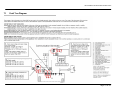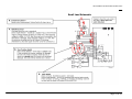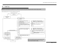
1
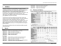
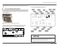
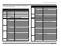
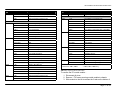
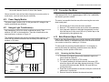
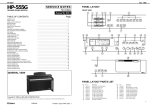
SERVICE MANUAL for 300, 500, and 800 Series Built-in Wall Ovens This manual contains information that is necessary for servicing the following Bosch electric built-in wall ovens: HBL8x50UC, HBL57x0UC, HBL56x0UC, HBL54x0UC, HBL35x0UC, HBL33x0UC, HBN56x0UC, HBN54x0UC, HBN35x0UC, HBN34x0UC, HBN3350UC This manual is designed to be used by qualified service personnel only. Due to the complexity and the risk of high-voltage electrical shock, Bosch does not recommend that customers service their own units. Models: HBL8x50UC, HBL57x0UC, HBL56x0UC, HBL54x0UC, HBL35x0UC, HBL33x0UC, HBN56x0UC, HBN54x0UC, HBN35x0UC, HBN34x0UC, HBN3350UC Service Manual for Bosch Built-in Wall Ovens TABLE OF CONTENTS 1 General ........................................................................................ 3 1.1 Models................................................................................... 3 1.2 Features and Options............................................................ 3 1.3 Data Plate.............................................................................. 4 1.4 Warranty................................................................................ 4 2 Operation..................................................................................... 4 2.1 Element Duty Cycles ............................................................. 4 2.1.1 Using Table 3 (Element Duty Cycles During Preheat) ... 5 2.2 Sequence of Events .............................................................. 5 2.3 Cooling Fans ......................................................................... 7 3 Component Accessibility........................................................... 8 3.1 Serviceable from Front .......................................................... 8 3.2 Serviceable from Top ............................................................ 8 3.3 Serviceable from Rear........................................................... 8 4 Service and Repair ..................................................................... 8 4.1 Doors..................................................................................... 8 4.1.1 Removing and Replacing the Door(s) ............................ 8 4.2 Door Latch/Motor Assembly .................................................. 9 4.3 Lamps.................................................................................. 10 4.3.1 Replacing Lamps ......................................................... 10 4.4 High Temperature Cutout (HTC) ......................................... 11 4.5 Convection Fan and Ring Element...................................... 11 4.6 Temperature Sensor ........................................................... 12 4.6.1 Setting Temperature Offsets ........................................ 12 4.7 Broil Element ....................................................................... 13 4.8 User Interface...................................................................... 13 4.8.1 Removing the User Interface ....................................... 14 4.9 PC Control Module (Relay Board)....................................... 15 4.10 Power Supply Module...................................................... 18 4.11 Halogen Light Transformer(s).......................................... 18 4.12 Convection Fan Motor ..................................................... 18 4.13 Bake Element (Upper Oven)............................................ 18 4.13.1 Removing the Bake Element........................................ 18 4.13.2 Reinstalling the Bake Element ..................................... 19 4.14 Cooling Fan Motor (Upper Oven) .................................... 19 5 6 7 8 9 Error Codes .............................................................................. 19 5.1 Error Code Table ................................................................ 19 5.2 Service Mode / Setting Option Code .................................. 20 5.2.1 HBL3/HBN3 ................................................................. 20 5.2.2 HBL5/HBN5 ................................................................. 21 5.2.3 HBL8............................................................................ 21 5.3 Option Codes ...................................................................... 22 Demo Mode............................................................................... 22 Troubleshooting....................................................................... 22 7.1 Fault Tree Diagram ............................................................. 23 7.2 Fault Tree ........................................................................... 25 7.3 Testing ................................................................................ 33 Wiring Diagrams and Schematics .......................................... 33 8.1 Wire Color Key.................................................................... 33 8.2 Strip Diagrams .................................................................... 34 Additional References ............................................................. 34 9.1 QuickFinder ........................................................................ 34 9.2 Technical Support............................................................... 34 Page 2 of 36 Service Manual for Bosch Built-in Wall Ovens 1 GENERAL There are nine HBL (30”) and five HBN (27”) models in various combinations and three colors (black, white, and stainless), included in the 2007 Bosch 300, 500, and 800 Series Built-in Wall Oven (BIWO) product line. These models include A (thermal), B (convection), and C (convection with ring element) oven cavities. Two in the series are combination models with microwaves – the HBL57x0UC (with HMB50x0 traditional microwave) and HBL8750UC (with HMB80x0 convection microwave). HBL54x0UC HBL34x0UC HBL33x0UC 1.2 Single oven with true convection Single oven with convection Single oven with thermal Features and Options Cavity configuration and features by model appear below. The 800 series models are stainless steel and have a glass user interface (touch panel) with graphical displays. 500 series models are available in black, white, and stainless, and have ergonomic, retractable dials. The 300 series models, also available in three color options, have ergonomic dials. Fast preheat capability, 2-hour selfclean, telescopic racks, and up to 16 cooking modes are among the features offered. The control panel and door skins on the stainless models are grade 304 stainless steel. 1.1 Table 1 Bosch 27” 300 and 500 Series Features by Model Models 27” Ovens HBN56x0UC HBN54x0UC HBN35x0UC HBN34x0UC HBN3350UC Double oven with thermal/true convection Single oven with true convection Double oven with convection/thermal Single oven with convection Single oven with thermal 30” Ovens HBL8750UC HBL8650UC HBL8450UC HBL57x0UC HBL56x0UC Combo with true convection oven/convection micro Double oven with true convection both cavities Single oven with true convection Combination with true convection oven /traditional micro Double oven with true convection/thermal Table 2 Bosch 30” 300, 500, and 800 Series Features by Model Page 3 of 36 Service Manual for Bosch Built-in Wall Ovens 1.3 Data Plate The data plate reflecting model number and FD number is located on the underside of the interface control panel, as shown in Figure 1. Bosch assumes no responsibility for any repairs made on our products by anyone other than authorized service technicians. Find the complete product warranty statement in the Use and Care Manual. 2 2.1 Figure 1 Data plate location The first 4 positions of the FD number reflect the year/month the product was built. FD numbers that begin with 87 were built in 2007; 88 = 2008; 89 = 2009, etc. NOTICE Be prepared to provide the complete Model Number and FD number printed on the data tag of the unit when contacting Bosch Customer Support or Technical Support for assistance. 1.4 OPERATION Element Duty Cycles A new PID algorithm controls the way in which the elements cycle on and off during each cooking mode duty cycle. Every minute, the oven temperature is compared to the set point and a recalculation occurs, which results in varied element cycle times rather than the standard fixed 60-second cycle. During Preheat, however, a 2-point control is still used and there is a defined element on-time. The following table reflects the duration and start point by Preheat mode, for cavity types A, B, and C. Technicians should have ample time to troubleshoot element problems during the ~10-minute preheat period. Warranty The product is warranted to be free from defects in materials and workmanship for a period of 12 months from date of purchase. Bosch will pay for all repair labor and replacement parts found to be defective due to materials and workmanship. Service must be provided by a Factory Authorized Service Agency, during normal working hours. Page 4 of 36 Service Manual for Bosch Built-in Wall Ovens Using the data in the table, below is an example of how the elements cycle on and off during a 60-second Preheat cycle in True Convection mode (see Cavity C): HBL8450UC built in 01/2008 (see columns labeled -1-) • Bake Element: After initial 30 seconds of the cycle, element turns on and remains on for the final 30 seconds of the cycle. • Ring Element: After initial 30 seconds of the cycle, element turns on and remains on for the final 30 seconds of the cycle (same as Bake Element). • Broil Element: Turns on at the beginning of the cycle (0) and remains on for the first 30 seconds of the cycle. HBL8450UC built in 08/2008 (see columns labeled -2-) • Bake Element: After initial 33 seconds of the cycle, element turns on and remains on for the final 27 seconds of the cycle. • Ring Element: After initial 36 seconds of the cycle, element turns on and remains on for the final 24 seconds of the cycle. • Broil Element: Turns on at the beginning of the cycle (0) and remains on for the first 27 seconds of the cycle. In Fast Preheat (available in cavities B and C with convection fan), the same elements reflected in the table are used, but the broil element is on ~10% longer, and the convection fan stays on as well. Table 3 Element duty cycles during preheat by cavity type. 2.1.1 Using Table 3 (Element Duty Cycles During Preheat) In Table 3, Duration is defined as the number of seconds an element is turned on (e.g., 12 indicates the element will be on for 12 seconds.) Start Point is defined as the point in the cycle at which the element will turn on (e.g., 30 indicates the element will turn on in the 30th second of the cycle). It is important to note that during regulation (regular cooking period that follows Preheat), different elements may be used and element duty cycles will vary. 2.2 Sequence of Events Figures 2 – 5 reflect the sequence of events which occur during Preheat for the various cooking modes. Page 5 of 36 Service Manual for Bosch Built-in Wall Ovens Figure 2 Sequence of Events during Preheat: Convection Bake & Roast/ Bake, Roast, Warm, Proof, Pizza, Pie, & Sabbath modes Figure 3 Sequence of Events during Preheat: Convection Broil/Broil modes Page 6 of 36 Service Manual for Bosch Built-in Wall Ovens Figure 4 Sequence of Events during Preheat: True Convection Figure 5 Sequence of Events during Preheat: Self-clean mode 2.3 Cooling Fans Cooling fans will run for two minutes after the oven has been shut off, regardless of the oven temperature. After two minutes, the fan will continue to run until the interior temperature of the cavity reaches a maximum of 350°. (Early models were programmed with a lower shut-off temperature, which resulted in a longer running time for the cooling fan.) Page 7 of 36 Service Manual for Bosch Built-in Wall Ovens 3 COMPONENT ACCESSIBILITY 3.1 Serviceable from Front Door Door latch/motor assembly Cavity lamps High Temperature Cutout (HTC) Convection ring element and convection fan assembly (except motor) Temperature sensor Broil element The user interface is serviceable from the front after sliding the oven out from the wall ~ 4 inches. 3.2 Serviceable from Top The PC control module (relay board) is serviceable from the top access panel after sliding the oven out from the wall ~16 inches. With the unit pulled completely away from the wall, the following components are serviceable from the top after removing the top panel: 3.3 Halogen light transformers Terminal block Power supply Serviceable from Rear With the unit pulled completely away from the wall and the back panel(s) removed, the following components can be serviced from the rear: 4 SERVICE AND REPAIR m CAUTION 9 9 9 4.1 Sheet metal parts often have sharp edges. Avoid injury by handling these parts with care. Turn off the electrical power circuit to the oven at the main junction box before servicing this unit. For those checks requiring the use of electrical power, exercise extreme care. Doors On double ovens, the Bosch logo is located on the lower oven outer door glass. 30” models ending with Customer Service Index (KI) /01 were produced with 4-pane doors. Subsequent models have 3-pane doors. 4.1.1 Removing and Replacing the Door(s) m CAUTION Avoid injury when removing and replacing oven doors. 9 Be sure oven is cool enough for handling. 9 Position hinges properly (see Figure 6). 9 Grasp only by sides, not by the handle. 9 Do not force door open or closed. 9 Handle with care–door weighs ~38 pounds. Convection fan motor Bake element Cooling fan(s) Page 8 of 36 Service Manual for Bosch Built-in Wall Ovens To remove the door… 1. Open door completely. 2. Flip hinge levers back to open as shown below. Figure 6 Opening the hinge lever 3. Close door until it remains open ~6 inches. 4. Using both hands, lift door up and out. To replace the door… 1. Position door as if it were open ~6 inches and insert hinges into slots. 2. Open door completely. 3. Flip hinge levers forward to close as shown below. 4.2 Door Latch/Motor Assembly The motorized door latch (MDL) mechanism (120V 5W) has 2 switches - the door switch and the lock/unlock switch. The latch will automatically lock when mode and temperature selectors are set to CLEAN, and unlock when the oven cools to ~490°F. It is serviced as an assembly. If the latch becomes stuck in the locked position, turning the unit off and back on will open the latch if the cavity temperature <450°. If latch is stuck in partially locked position, press SELF CLEAN, then ON/OFF. The latch can be tested in Service mode. To remove the latch/motor assembly: 1. Remove 3 T20 screws securing trim piece to frame (do not remove 2 screws on either side of latch). 2. Pull trim forward about 1”, then slightly to the right or left to clear the screw tab (see Figure 8). 3. Slip hands under trim and lift upper plate while sliding trim and latch toward you. Screw Tab Door Switch Lock/ Unlock Switch Figure 7 Closing hinge lever 4. Close and open door to check operation. • • Hinges should be replaced in pairs. The 300, 500, and 800 series ovens do not have serviceable hinge receivers. Figure 8 Door latch/motor assembly Page 9 of 36 Service Manual for Bosch Built-in Wall Ovens 4.3 4.3.1 Lamps The operation of the cavity lights is determined by the state of the lights, the state of the oven, and the button(s) pressed. The table below illustrates the results after each button press. Current state of lights Upper Lower OFF OFF Current state of oven Upper Lower OFF OFF ON OFF OFF ON ON ON Key(s) Pressed DOES NOT MATTER UPPER+LIGHT LOWER+LIGHT DOES NOT MATTER ON OFF OFF ON OFF ON OFF OFF ON ON DOES NOT MATTER DOES NOT MATTER OFF ON OFF ON OFF ON OFF OFF ON ON DOES NOT MATTER DOES NOT MATTER ON ON OFF ON OFF ON OFF OFF ON ON DOES NOT MATTER DOES NOT MATTER LIGHT LIGHT LIGHT LIGHT LIGHT LIGHT LIGHT LIGHT UPPER+LIGHT LOWER+LIGHT LIGHT LIGHT LIGHT LIGHT UPPER+LIGHT LOWER+LIGHT LIGHT LIGHT LIGHT LIGHT UPPER+LIGHT LOWER+LIGHT Resulting state of lights Upper Lower ON ON ON OFF OFF ON ON ON ON OFF OFF ON OFF OFF ON OFF OFF ON OFF OFF ON OFF OFF ON OFF ON OFF OFF ON OFF OFF ON OFF OFF ON OFF OFF OFF ON OFF OFF ON OFF ON OFF OFF ON OFF Replacing Lamps The number and type of lamps in each cavity will vary, depending on model. Two types of bulbs are used: 10-watt, 12-volt bi-pin halogen light bulbs or 40- (30”) or 25-watt (27”) incandescent appliance bulbs. Handle all bulbs with a clean, dry cloth. m CAUTION 9 9 9 Turn off power to the oven at the fuse or breaker box–light socket is live with door open. Be sure oven and lights are cool to the touch. Handle glass lenses carefully. 4.3.1.1 Halogen Side Lamp (Vertical-style) 1. Remove racks and rack support. 2. Firmly push the top mounting clip up and back (toward oven wall), until it releases the glass cover. Top mounting clip Table 4 Operation of cavity lights The lights will automatically illuminate whenever the oven door is opened, and turn off when the door is closed. Figure 9 Vertical-style side lamp Page 10 of 36 Service Manual for Bosch Built-in Wall Ovens 3. Pull the halogen bulb straight out from its socket. 4. Using a clean, dry cloth, insert the new bulb. 5. Reinsert the bottom of the glass cover (smooth side out) into the bottom clip, and firmly push the top of the cover into the upper clip until it snaps into place. 6. Restore power to the unit. 4.3.1.2 Halogen Side Lamp (Horizontal-style) 1. Remove racks and rack support. 2. Slide tip of flat-blade screwdriver between fixing clip and lamp housing, while supporting lens cover along bottom edge. Figure 11 Round halogen ceiling lamp (L); traditional lamp with 40W or 25W appliance bulb (R). 4.4 Holder clip Slide screwdriver between fixing clip and lamp housing. Figure 10 Horizontal-style side lamp 3. 4. 5. 6. 7. Gently twist screwdriver to loosen the lens cover. Remove cover and fixing clip. Grasp halogen bulb and pull it straight out from its socket. Using a clean, dry cloth, insert new bulb into socket. Reinsert lens cover into the holder clip and gently push back until fixing clip snaps into place. 8. Restore power to the unit. 4.3.1.3 Halogen Ceiling Lamp and Incandescent Cavity Lamp 1. Unscrew glass cover. 2. Pull halogen bulb straight out of its socket, or unscrew appliance bulb. 3. Using a clean, dry cloth, insert the new bulb. 4. Replace the glass cover. 5. Restore power to the unit. High Temperature Cutout (HTC) The HTC is a normally closed switch which will interrupt the relay supply voltage in the event of a high temperature event caused by a malfunctioning control module. The HTC is located in the plenum, behind and to the left of the MDL. Although it cannot be easily removed or replaced, a screwdriver can be used to reach the reset button located on the top center of the HTC after the latch plate has been removed. 4.5 Convection Fan and Ring Element All models except the HBL33/HBN33 and the lower cavity of the HBL56/HBN56 and HBL35/HBN35 models, which have a thermal oven cavity, are configured with convection capabilities in the upper and/or lower ovens. The HBL34/HBN34 and HBL35/HBN35 models have a convection fan only, and the remaining models with convection cavities have both a convection fan and a convection (also called a “ring” or “3rd”) element, which gives the ovens true (or genuine European) convection capability. Depending on the cooking mode selected, the fan may be used, with or without the ring element, to circulate heat evenly throughout the cavity in various cooking modes. Page 11 of 36 Service Manual for Bosch Built-in Wall Ovens The ring element (240V 2000W) and/or fan blade are easily accessed on the rear wall of the oven cavity behind the convection baffle. The convection fan motor is accessible only from the rear of the unit. Refer to the Element Strip Diagram to test the element at the control module, or 1. Remove 2 T20 screws on either side of the element terminals. 2. Pull the element toward you so that terminal wires are inside the oven cavity. 3. Disconnect the wires from the terminals. 4. Use an ohmmeter to check for resistance of ~29 ohms. 4.6 Temperature Sensor Use an ohmmeter to check the resistance of the sensor. Normal ranges (based on cavity temperature) are shown in Table 5. through the HBL8, HBL5/HBN5 menu options by pressing FAST until the Oven temp or Probe temp option is reached. On the HBL3/HBN3 models, press TEMP to advance through the menu. PREHEAT 4.6.1 Setting Temperature Offsets In some cases, it may be necessary to adjust the oven temperature if food is consistently under- or over-cooked. Temperature offsets can be entered by the customer from the Customer Settings or Setup menu to raise or lower the cavity temperature during Bake, Convection Bake, Roast, Convection Roast, and Speed Convection modes (all heating modes which operate between 250°F and 550°F). A +25° offset will result in a cavity temperature of 350° when the temperature knob is set to 325° for any of the cooking modes listed above. Similarly, a -25° offset will result in a cavity temperature of 300° when the temperature knob is set to 325°. The adjusted temperature cannot be less than 250°F or greater than 550°F. 4.6.1.1 HBL3/HBN3 The oven must be turned off with no timer running in order to access the menu. Table 5 Normal temperature sensor resistance readings temperature Real-time cavity and probe temperatures can be measured while in Service Mode (refer to the section entitled Service Mode or the Service Guide for instructions). After entering Service mode, advance 1. Press and hold Temp for two seconds to access the Customer Settings menu. 2. Press Timer to advance through the menu. 3. When CS7: Oven Temperature Offset (for upper/single oven) or CS8: Oven Temperature Offset (for lower oven) appears, use the Settings dial to set the desired value. 4. Confirm by pressing Timer. 5. Press Temp to exit the Customer Settings menu. 4.6.1.2 HBL5/HBN5 The Cooking Mode dial and Settings dial must be in the Off position in order to access the menu. Page 12 of 36 Service Manual for Bosch Built-in Wall Ovens 1. Press and hold Info for two seconds to access the Setup menu. 2. Press the arrows UV to advance through the menu to Oven Temperature Offset. 3. Rotate the Settings dial to set the desired value. 4. Press the arrows UV to advance to the next menu item, which will confirm the offset entry. 5. Press Info to exit the Setup menu. Note: for double ovens, an offset can be entered separately for each oven by selecting either Up. Offset or Lo. Offset from the menu. 2. Remove the 2 T20 screws on either side of the element terminals. 3. Pull the element toward you so that the terminal wires are inside the oven cavity. 4. Disconnect the wires from the inner broil element terminals. 5. Use an ohmmeter to check for resistance of ~16 ohms. 4.8 User Interface Figure 12 reflects the variations of the B1, B2, and B3 user interfaces used in the Bosch ovens. 4.6.1.3 HBL8x50 The oven must be Off in order to access the menu. 1. Press and hold Info for two seconds to access the Setup menu. 2. Press the arrows UV to advance through the menu to Oven Temperature Offset. 3. Press + and – to set the desired value. 4. Press the arrows UV to advance to the next menu item, which will confirm the offset entry. 5. Press Info to exit the Setup menu. Note: for double ovens, an offset can be entered separately for each oven by selecting either Up. Offset or Lo. Offset from the menu. 4.7 Broil Element All Bosch models have a recessed 10-pass (240V 3600W) broil element. Refer to the Element Strip Diagram to test the element at the control module, or 1. Remove the 2 T20 screws securing the element to the broil reflector. Page 13 of 36 Service Manual for Bosch Built-in Wall Ovens The user interface control board is assembled onto a chassis and the entire assembly is serviced as a single unit. 4.8.1 Removing the User Interface 1. Slide unit out from wall ~ 4 inches. 2. Remove 2 T20 bolts from each side. 3. Grasp one corner of the interface panel and lift upward, then pull it toward you (see Figure 13). 4. Repeat on the other side. 5. Disconnect the 3-wire yellow harness leading to PC control module. 1 2 Figure 13 Each side of the user interface bracket has a tab n that rests in a slot on the chassis u-profile o. To remove the user interface board and chassis from the manifold bracket, remove the 10 binding-head T20 screws securing the interface chassis to the bracket (these screws are unique to the interface – notice the serrated underside). If the user interface assembly was difficult to remove, break the metal tabs off (n) to make it easier to reinstall; use pliers to bend the tabs back and forth until they break off. Figure 12 Bosch user interfaces Page 14 of 36 Service Manual for Bosch Built-in Wall Ovens After installing a new user interface board, always reset the oven and test. 4.9 PC Control Module (Relay Board) To access the PC control module, pull the unit out from the wall 15-16 inches, and remove the access panel (3 T20 screws) on the top of the unit. See Figure 14. Figure 14 PC Control Module is visible after removing access panel. Whenever possible, conduct troubleshooting tests at the control module. Refer to Figures 15 -16 for plug and relay locations. Rear X102 X101 X103 X104 X105 X106 X107 X209 X1 X2 X110 X210 X204 X203 X3 X202 X201 X205 Front X206 X207 Figures 16 Relay locations on the double oven control module NOTICE Figure 15 Plug locations on the double oven control module More than 75% of the control modules returned to the factory are fully functional. Before diagnosing a bad control module, be sure to disconnect and reconnect each wire/wire harness. Page 15 of 36 Service Manual for Bosch Built-in Wall Ovens Use Table 6 as a reference guide to the plugs, pins, and wire colors found on the PC control module. PLUG NO X1 X2 X3 X108* X101 PIN NO X103 X104 FROM/TO COMMUNICATION 5-position card-edge Control Module to Power Supply Module connector - WH 3-position card-edge Control Module to User Interface Module connector - YE 3-position card-edge Control Module to Factory Service Port connector - YE 2-position card-edge Control Module to Meat Probe connector - WH/GN UPPER/SINGLE CAVITY ELEMENTS 1-OR K102 Relay to Bake Element X110 PIN NO FROM/TO 3-Blank N/A 4-BK L1 to K106 Relay 5-BK L1 to K106 Relay 6-Blank N/A 7-Not Used N/A 8-YE K106 Relay to Broil Element 1-BU High Temperature Cutout (HTC) 2-Not Used N/A 3-BU High Temperature Cutout (HTC) UPPER/SINGLE CAVITY SMALL LOAD X105 1-Blank N/A L1 to K102 Relay 2-YE K112 Relay to Convection Fan 3-Blank N/A 3-BU/WH K114 Relay to Cooling Fan (L) 4-BK L1 to K104 Relay 4-BU K115 Relay to Cooling Fan (H) 5-Blank N/A 5-BN K115 to Light Transformer 6-BU** K104 Relay to Ring Element 6-Blank N/A 1-YE K003 DLB Relay to Broil Element 7-BN K117 Relay to Motorized Door Latch (MDL) 2-Not Used N/A 8-RD L2 to K117 Relay 3-Blank N/A 1-YE Door Switch 4-RD L2 to K003 DLB Relay 2-YE Door Switch 5-RD L2 to K003 DLB Relay 3-Not Used N/A 1-BU** K002 DLB Relay to Ring Element 4-YE/BK Latch Switch 2-RD L2 to K002 DLB Relay 5-OR/BK Latch Switch 3-Blank N/A 6-VT/WH Door Switch 4-RD L2 to K001 DLB Relay 5-Blank N/A 6-OR 2-BK X102 PLUG NO X106 7-BN/WH Door Switch 1-WH Hall Effect Sensor K001 DLB Relay to Bake Element 2-BK Hall Effect Sensor 7-Blank N/A 3-RD Hall Effect Sensor 1-Blank N/A 4-WH Temperature Sensor 2-Blank N/A 5-WH Temperature Sensor X107 Page 16 of 36 Service Manual for Bosch Built-in Wall Ovens PLUG NO X110 PIN NO FROM/TO 1-BU High Temperature Cutout (HTC) 2-Not Used N/A 3-BU High Temperature Cutout (HTC) PLUG NO X202 X203 X204 X210 FROM/TO 3-BU High Temperature Cutout (HTC) LOWER CAVITY SMALL LOAD X205 LOWER CAVITY ELEMENTS X201 PIN NO 1-YE K212 Relay to Convection Fan 2-RD L2 to K217 Relay 1-BU ** K204 Relay to Ring Element 3-BN K216 to Light Transformer 2-Blank N/A 4-Not Used N/A 3-Blank N/A 5-Not Used N/A 4-BK ** L1 to K204 Relay 6-BN K217 Relay to Motorized Door Latch (MDL) 5-BK L1 to K202 Relay 1-YE Door Switch X206 6-Blank N/A 2-YE Latch Switch 7-OR K202 Relay to Bake Element 3-YE/BK Latch Switch 1-RD L2 4-OR/BK Latch Switch 2-RD L2 to K006 DLB Relay 5-Not Used N/A 3-Not Used N/A 6-VT/WH Door Switch 4-Not Used N/A 5-YE K006 DLB Relay to Broil Element 1-OR K004 DLB Relay to Bake Element 2-Not Used N/A 2-Not Used N/A 3-WH Temperature Sensor 3-RD L2 to K004 DLB Relay 4-RD Hall Effect Sensor 4-Blank N/A 5-BK Hall Effect Sensor 5-RD ** L2 to K005 DLB Relay 6-WH Temperature Sensor 6-Blank N/A 1-BU/WH X105-P3 to Cooling Fan (L) 2-BU X105-P4 to Cooling Fan (H) 7-BU ** K005 DLB Relay to Ring Element 1-YE K206 to Broil Element 2-Not Used N/A 3-Blank N/A 4-BK L1 to K206 Relay 5-BK L1 to K206 Relay 1-BU High Temperature Cutout (HTC) 2-Not Used N/A X207 X209 7-BN/WH Door Switch 1-WH Hall Effect Sensor * Not used on HBL3, HBN3 ** HBL8, HBL5, HBN5 only Table 6 Plugs and pins on the PC control module To remove the PC control module… 1. Disconnect all wires. 2. Remove 1 T20 screw securing control module to chassis. 3. Slide module to the left to release the 3 tabs on the bottom of Page 17 of 36 Service Manual for Bosch Built-in Wall Ovens the module bracket from the 3 slots in the chassis. Always reset the oven and test after changing the control module. In some cases, a second reset may be necessary. 4.10 Power Supply Module The power supply module (9.6V 12.5W) provides DC voltage to the control module and user interface. 4.11 4.12 The convection fan motor is 120V 29W. To test the motor, check for 120V across X105 / Pin 2 (upper/single) or X205 / Pin 1 (HBL8650) and chassis ground or neutral. The motor is accessible from the rear, after removing the rear outer sheet metal panel. 1. Disconnect the 2 wires from the motor terminals. 2. Remove 3 T20 screws from the arms of the motor assembly. 3. Use a tap and a hammer to dislodge the assembly from the clips that secure it to the rear of the unit. (Position tap on the arm secured by the rightmost clip.) Halogen Light Transformer(s) One transformer (120V-12V 40VA) is utilized per cavity. Triac switches 120 VAC to the transformer. There are 4 terminals on the new transformer, as shown in Figure 16. The resistance between the primary terminals should measure ~12.8 ohms and the resistance between the secondary terminals should measure ~0.32 ohms. Secondary LINE Terminals Convection Fan Motor 4.13 Bake Element (Upper Oven) Refer to the Strip Element Diagram to test the element (240V 2000W) at the control module, or disconnect the wires from the terminals and use a meter to check for a reading of ~29 ohms. To clear a path for removing the bake element, it is necessary to remove the vertical air channel(s) and disconnect wires. Before proceeding, note the position of the wires. Primary LOAD Terminal 4.13.1 Removing the Bake Element 1. Pull wires out of plastic purse locks attached to upper and lower vertical air channels. 2. Remove upper air channel (4 T20 screws). 3. To create a pathway for the bake element, disconnect OR BN X105-6 X205-4 OR LINE WH Terminal Block LOAD OR wires from upper and lower bake element terminals; YE from convection element terminals, BU/WH, BU, and WH from cooling fan motor. 4. Drape the wires/harnesses to the side so they do not block the element as it is pulled out. 5. Remove the screw between the element terminals. Figure 17 Halogen light transformer Page 18 of 36 Service Manual for Bosch Built-in Wall Ovens 6. Tuck insulation up into the oven wall as necessary. 7. While holding element terminals, lift element upward to clear the outer edge of the compartment. 8. Hold element on both sides and lift upward as you slide it straight out. 4.13.2 If the Hall effect sensor does not detect fan rotation, an error will display. To test the upper fan at the control module, check voltage across X105 / Pin 3 or 4 and neutral. 1. Remove 3 T20 screws securing the fan to the mounting bracket. 2. Remove 3 T20 screws securing the bracket to the oven housing. 3. Slide bracket up and out to release it from the 2 tabs holding it in position. 4. Remove 3 T20 screws from the right side of the unit’s top panel. 5. Lift the right corner of the top panel and remove the fan/motor. Reinstalling the Bake Element There are 2 tabs inside the element cavity, and the front tab will prevent the element from going in all the way. Use a ruler or the vertical air channel (after removing plastic purse locks) as a tool to guide the element back in. 1. Place the tool inside the cavity, on top of the tab, then insert the element on top of the tool and slide it in. 2. After the element is beyond the front tab, remove the tool. 3. Complete the installation. 4. Replace the plastic purse locks clips if they were removed from the vertical air channel. 4.14 Cooling Fan Motor (Upper Oven) 5 ERROR CODES A Service Guide with error code information, wiring diagrams, and instructions for entering Service mode (if applicable) is packed with every unit. Find it on the underside of the upper plenum access panel as shown in Figure 19. Each 2-speed cooling fan (120V 28/41W) has 3 terminals (high speed, low speed, and neutral) and a Hall effect sensor. There is tape around the motor windings and the terminals are labeled N, H, and L for reference, as shown in Figure 18. Figure 19 Location of Bosch Built-in Oven Service Guide 5.1 Figure 18 Tape on cooling fan windings marked to designate terminals Error Code Table The following table is included in the oven Service Guide. The error codes which begin with E2 apply to the lower cavity of double ovens. Diagrams referenced in the table can also be found in the appropriate Service Guide. Page 19 of 36 Service Manual for Bosch Built-in Wall Ovens CODE E000 DESCRIPTION Wrong module combination E003 Electronics too hot E005 Communication error E009 ROM check error in user interface E010 E011 Data memory error in user interface Continuous pushing of single key E012 Defective User Interface PCB temp. sensor ON/OFF key does not work Continuous pushing of keys E014 E032 E101/E201 E104/E204 E106/E206 E107/E207 E115/E215 E116 Cvt 1/Cvt 2 Temp. sensor open Cvt 1/Cvt 2/Temp. sensor shorted Cvt 1/Cvt 2 Door latch does not lock Cvt 1/Cvt 2 Door latch does not unlock Cvt 1/Cvt 2 Temp. in unlocked cavity too high Cvt 1/Cvt 2 Probe error CAUSE/ACTION Control module and user interface are mismatched. Set Option Code properly. User interface exceeds 185°F/85°C Loss of communication between user interface and control module at start-up. Check for ~4.9Vdc on middle pin of communication harness. Check connections of all communication lines and control module inputs. User interface not getting all information from control module at start-up. Check for loss of communication or disconnected wire somewhere in unit Check user interface assembly. Inspect touch PCB. 10 seconds of multiple keys being pressed. Refer to Diagram 2/4 Refer to Diagram 2/4 Refer to Diagram 2/4 Refer to Diagram 2/4 Standard probe module is part of the control module. Refer to Diagram 1. CODE E118/E218 DESCRIPTION Cvt 1/Cvt 2 Cooling fan supervision error E122 E123 E124/E224 Cvt 1/ Probe sensor temp. too high or shorted. Cvt 1/ Probe sensor temp. too low Cvt 1/Cvt 2 Door switch error E126/E226 Cvt 1/Cvt 2 Door latch error E303 Electronics too hot E309 E310 E312 ROM Check error in control module Data memory error in control module Defective control module PCB temp. sensor CAUSE/ACTION Cooling fan speed is too low or too high. Refer to Diagram 2/4. Ensure wire harness not touching motor or pinched. Confirm plenum not touching fan end cap. Check Hall Effect Sensor connection. Check probe receptacle and harness. Door switch is in undefined state. Refer to Diagram 2/4. Door latch is in an undefined state. Refer to Diagram 2/4. Control module exceeds 212°F/100°C. Table 7 Error codes 5.2 Service Mode / Setting Option Code When both the user interface board and control module (relay board) are replaced, the oven will display E000 (Wrong Module Combination) fault code at start-up. To resolve, place the unit in Service Mode and manually set the Option Code. 5.2.1 HBL3/HBN3 To enter service mode… 1. Press and hold TEMP. 2. Press and hold COOK TIME. 3. Rotate the Cooking Mode dial out of the OFF position. 4. Release the two buttons. Page 20 of 36 Service Manual for Bosch Built-in Wall Ovens To set the option code… 4. Locate the 4-digit code on the label near the PC Control Board in the upper plenum or in Table 8 below. 5. Set the Option Code by rotating the Settings dial. Figure 20 HBL3/HBN3 User interface To set the option code… 5. Locate the 4-digit code on the label near the PC Control Board in the upper plenum or in Table 8 below. 6. Press TEMP to advance to the Option Code (OC) screen. 7. Press COOK TIME. 8. Rotate the Settings dial to change the code. To exit service mode… 9. Rotate the Cooking Mode dial to the OFF position. 10. Rotate the Settings dial to set the time. To exit service mode… 6. Rotate the (upper oven) Cooking Mode dial to the OFF position. 7. Rotate the Settings dial to set the time. 8. Press and rotate the Settings dial to set the date. (See Use and Care Manual for further information about setting time and date.) To reset the oven… 9. Unplug the unit or turn the power off at the circuit breaker for 30 seconds. 10. Set the current time and date (see 7 and 8 above). 5.2.3 To reset the oven… 11. Unplug the unit or turn the power off at the circuit breaker for 30 seconds. 12. Rotate the Settings dial to set the time. 5.2.2 HBL5/HBN5 HBL8 To enter service mode… 1. Press and hold START. 2. Press and hold FAST PREHEAT. 3. Press ON/OFF. 4. Release all three buttons. E000 To enter service mode… 1. Press and hold START and FAST PREHEAT. 2. Rotate the Cooking Mode dial out of the OFF position. 3. Release the two buttons. Wrong Figure 22 HBL8 User interface To set option code… 5. Locate the 4-digit code on the label near the PC Control Board in the upper plenum or in Table 8 below. 6. Press FAST PREHEAT to advance to the Option Code menu selection. Figure 21 HBL5/HBN5 User interface Page 21 of 36 Service Manual for Bosch Built-in Wall Ovens 7. 8. Follow the instructions on the oven display and enter the appropriate code. To confirm the change after the code has been entered, press FAST PREHEAT to advance to the next menu item. 7 TROUBLESHOOTING Use the Fault Tree Diagram and Fault Tree on the following pages to guide troubleshooting efforts. To exit service mode… 9. Press ON/OFF to exit Service Mode. 10. Follow the instructions on the display to set the time and the date. To reset the oven… 11. Unplug the unit or turn the power off at the circuit breaker for 30 seconds. 12. Follow the instructions on the display to set the current time and date. Always confirm that the error has been cleared and the oven is functioning normally after setting the option code. 5.3 Option Codes Model HBL33 HBL34 HBL35 HBL54 HBL56 HBL57 HBL84 Option Code 0150 0250 0750 0351 0851 0351 0351 Model HBL86 HBL87 HBN33 HBN34 HBN35 HBN54 HBN56 Option Code 0951 0351 0140 0240 0740 0341 0841 Table 8 Bosch option codes 6 DEMO MODE The display and lights will work on 120VAC when the black and red wires are tied together. Page 22 of 36 Service Manual for Bosch Built-in Wall Ovens 7.1 Fault Tree Diagram Page 23 of 36 Service Manual for Bosch Built-in Wall Ovens Page 24 of 36 Service Manual for Bosch Built-in Wall Ovens 7.2 Fault Tree Page 25 of 36 Service Manual for Bosch Built-in Wall Ovens Page 26 of 36 Service Manual for Bosch Built-in Wall Ovens Page 27 of 36 Service Manual for Bosch Built-in Wall Ovens Page 28 of 36 Service Manual for Bosch Built-in Wall Ovens Page 29 of 36 Service Manual for Bosch Built-in Wall Ovens Page 30 of 36 Service Manual for Bosch Built-in Wall Ovens Page 31 of 36 Service Manual for Bosch Built-in Wall Ovens Page 32 of 36 Service Manual for Bosch Built-in Wall Ovens 7.3 Testing Test with wire harness off at pin header or with circuits open. Plug X102 and X103 Pins 4, 5 X10⁵ 7 2, 4 Operates Upper oven double line break relay coil Upper door latch motor X105 6 X10⁵ 1 Upper oven convection motor Rotisserie motor X106 1 (common), 6, 7 Upper oven door latch X107 4, 5 Upper oven sensor X107 1, 2, 3 Cooling fan motors X207 1,4,5 X202 and X203 1, 2 X205 6 X205 3, 5 1 Lower oven double line break relay coil Lower door latch motor Lower oven convection motor Explanation No fail code. If double line break relay does not close, L2 (120 volts) will not reach upper oven bake, broil, convection elements. Will accept all modes except selfclean. When oven set to self-clean, display will be on constantly, doors will not lock and self-clean will not start. E106 will appear. No fail code. Lower oven convection motor will not work. No failure code. Rotisserie will not rotate. If latch position is not detected during normal operation, E124/126 will be displayed. Controls function normal. When sensor opens, E101 code will appear. If sensor shorts, E104 will appear. Cooling fan is on constantly. Will accept modes. In ~45 seconds, E118 will appear in upper oven display or E218 will appear in lower oven display when hall sensor does not detect fan rotation. No fail code. If double line break relay does not close, L2 (120 volts) will not reach lower oven bake, broil, convection elements. Will accept all modes except selfclean. When oven set to self-clean, display will be on constantly, doors will not lock and self-clean will not start. E206 will appear. No fail code. Lower oven convection motor will not work. Relay will snap closed. Plug X206 Pins 1 (common), 6, 7 Operates Lower oven door latch X207 3, 6 Lower oven sensor X2 Sends display signal to display X2 Sends communication signals to display Explanation If latch position is not detected during normal operation, E224/226 will be displayed. Control functions normal. When sensor opens, E201 code will appear. If sensor shorts, E204 will appear. Cooling fan is on constantly. Glass control panel is completely dead. 3-position connector (ground/voltage/data line) should measure 9.6 VDC. If no communication between electronic modules, E005 will display. Connector positions 1-2 should measure ~5 VDC. Table 9 Troubleshooting 8 WIRING DIAGRAMS AND SCHEMATICS The wire color key (Table 10) and element strip diagrams (Figures 2324) are shown below. For schematics, please refer to the Built-in Oven Service Guide (Wiring Diagram) which can be found on QuickFinder or in the upper oven plenum, near the control module. 8.1 Wire Color Key BK GN VT BN/WH VT/WH Black Green Violet Brown/White Violet/White BN OR WH BU/WH YE/BK Brown Orange White Blue/White Yellow/Black BU RD YE OR/BK Blue Red Yellow Orange/Black Table 10 Wire color key Page 33 of 36 Service Manual for Bosch Built-in Wall Ovens 8.2 Strip Diagrams 9 ADDITIONAL REFERENCES 9.1 QuickFinder For further information, please refer to the following documents on QuickFinder: Figure 23 Upper (Cavity 1) / Single oven strip diagram Wiring Diagram (Built-in Oven Service Guide) Installation Instructions Use and Care Manual HMB8020/8050/8060 Convection Microwave Use and Care Manual HMB8020/8050/8060 Convection Microwave Installation Instructions HMB8020/8050/8060 Convection Microwave Service Manual HMB5020/5050/5060 Traditional Microwave Use and Care Manual HMB5020/5050/5060 Traditional Microwave Installation Instructions HMB5020/5050/5060 Traditional Microwave Service Manual Exploded views, parts lists, and related service and parts notes are also available on QuickFinder. Visit http://portal.mch.bshg.com/portal. NOTICE Not all service parts are shown on the QuickFinder exploded views; review the parts list for additional information. 9.2 Technical Support To reach Bosch technical support, call the toll free TechLine at Figure 24 Lower (Cavity 2) oven strip diagram Page 34 of 36 Service Manual for Bosch Built-in Wall Ovens 888 522-6724. Technicians are available to assist you Monday – Friday, between the hours of 5am and 5pm, Pacific Time. Page 35 of 36 Service Manual for Bosch Built-in Wall Ovens Notes 58300000139357 ARA EN B BSH Home Appliances Corporation 5551 McFadden Ave., Huntington Beach, CA 92649 February 2009 Page 36 of 36