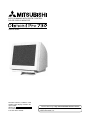
1
AUTO-SCANNING WITH DIGITAL CONTROL
COLOR DISPLAY MONITOR
USER’S GUIDE
For future reference, record the serial
number of your display monitor in the
space below:
SERIAL No.
The serial number is located on the
rear cover of the monitor.
Internet Home Page: http://www.mitsubishi-electric.com.au/
®
Supplying Windows 95/98/2000 INF File download service, new
product information, etc.
- ii -
RADIO INTERFERENCE REGULATIONS STATEMENT FOR U.S.A.
This equipment has been tested and found to comply
with the limits for a Class B digital device, pursuant to
Part 15 of the FCC Rules. These limits are designed to
provide reasonable protection against harmful interference in a residential installation. This equipment generates, uses and can radiate radio frequency energy and,
if not installed and used in accordance with the instructions, may cause harmful interference to radio communications. However, there is no guarantee that interference will not occur in a particular installation. If this
equipment does cause harmful interference to radio or
television reception, which can be determined by turning the equipment off and on, the user is encouraged to
try to correct the interference by one or more of the
following measures:
-
-
Reorient or relocate the receiving antenna.
Increase the separation between the equipment and
receiver.
Connect the equipment into an outlet on a circuit
different from that to which the receiver is connected.
Consult the dealer or an experienced radio/TV technician for help.
THIS PRODUCT HAS BEEN TESTED AND FOUND
TO COMPLY WITH THE LIMITS. USE IT TO REDUCE THE POSSIBILITY OF CAUSING INTERFERENCE TO RADIO, TELEVISION, AND OTHER
ELECTRIC DEVICES.
NO USER SERVICEABLE PARTS INSIDE. DO
NOT ATTEMPT TO MODIFY THIS EQUIPMENT. IF
MODIFIED, YOUR AUTHORITY TO OPERATE THIS
EQUIPMENT MIGHT BE VOIDED BY FCC.
- iii -
Below you will find a brief summary of the environmental
requirements met by this product. The complete
environmental criteria document may be ordered from:
TCO Development
SE-114 94 Stockholm, Sweden
Fax: +46 8 782 92 07
Email (Internet): [email protected]
Current information regarding TCO’99 approved and
labelled products may also be
obtained via the Internet, using the address:
http://www.tco-info.com/
Congratulations!
You have just purchased a TCO’99 approved and labelled
product! Your choice has provided you with a product
developed for professional use. Your purchase has also
contributed to reducing the burden on the environment and
also to the further development of environmentally adapted
electronics products.
Environmental requirements
Flame retardants
Flame retardants are present in printed circuit boards,
cables, wires, casings and housings. Their purpose is to
prevent, or at least to delay the spread of fire. Up to 30% of
the plastic in a computer casing can consist of flame
retardant substances. Most flame retardants contain
bromine or chloride, and those flame retardants are
chemically related to another group of environmental toxins,
PCBs. Both the flame retardants containing bromine or
chloride and the PCBs are suspected of giving rise to
severe health effects, including reproductive damage in
fish-eating birds and mammals, due to the bio-accumulative*
processes. Flame retardants have been found in human
blood and researchers fear that disturbances in foetus
development may occur.
The relevant TCO’99 demand requires that plastic
components weighing more than 25 grams must not contain
flame retardants with organically bound bromine or chlorine.
Flame retardants are allowed in the printed circuit boards
since no substitutes are available.
Why do we have environmentally labelled computers?
In many countries, environmental labelling has become an
established method for encouraging the adaptation of
goods and services to the environment. The main problem,
as far as computers and other electronics equipment are
concerned, is that environmentally harmful substances are
used both in the products and during their manufacture.
Since it is not so far possible to satisfactorily recycle the
majority of electronics equipment, most of these potentially
damaging substances sooner or later enter nature.
There are also other characteristics of a computer, such as
energy consumption levels, that are important from the
viewpoints of both the work (internal) and natural (external)
environments. Since all methods of electricity generation
have a negative effect on the environment (e.g. acidic and
climate-influencing emissions, radioactive waste), it is vital
to save energy. Electronics equipment in offices is often left
running continuously and thereby consumes a lot of energy.
Cadmium* *
Cadmium is present in rechargeable batteries and in the
colour-generating layers of certain computer displays.
Cadmium damages the nervous system and is toxic in high
doses. The relevant TCO’99 requirement states that
batteries, the colour-generating layers of display screens
and the electrical or electronics components must not
contain any cadmium.
What does labelling involve?
This product meets the requirements for the TCO’99 scheme
which provides for international and environmental labelling
of personal computers. The labelling scheme was developed
as a joint effort by the TCO (The Swedish Confederation of
Professional Employees), Svenska Naturskyddsforeningen
(The Swedish Society for Nature Conservation) and Statens
Energimyndighet (The Swedish National Energy
Administration).
Mercury* *
Mercury is sometimes found in batteries, relays and
switches. It damages the nervous system and is toxic in
high doses. The relevant TCO’99 requirement states that
batteries may not contain any mercury. It also demands
that mercury is not present in any of the electrical or
electronics components associated with the labelled unit.
Approval requirements cover a wide range of issues:
environment, ergonomics, usability, emission of electric
and magnetic fields, energy consumption and electrical
and fire safety.
CFCs (freons)
The relevant TCO’99 requirement states that neither CFCs
nor HCFCs may be used during the manufacture and
assembly of the product. CFCs (freons) are sometimes
used for washing printed circuit boards. CFCs break down
ozone and thereby damage the ozone layer in the
stratosphere, causing increased reception on earth of
ultraviolet light with e.g. increased risks of skin cancer
(malignant melanoma) as a consequence.
The environmental demands impose restrictions on the
presence and use of heavy metals, brominated and
chlorinated flame retardants, CFCs (freons) and chlorinated
solvents, among other things. The product must be prepared
for recycling and the manufacturer is obliged to have an
environmental policy which must be adhered to in each
country where the company implements its operational
policy.
The energy requirements include a demand that the
computer and/or display, after a certain period of inactivity,
shall reduce its power consumption to a lower level in one
or more stages. The length of time to reactivate the computer
shall be reasonable for the user.
Labelled products must meet strict environmental demands,
for example, in respect of the reduction of electric and
magnetic fields, physical and visual ergonomics and good
usability.
Lead* *
Lead can be found in picture tubes, display screens,
solders and capacitors. Lead damages the nervous system
and in higher doses, causes lead poisoning. The relevant
TCO´99 requirement permits the inclusion of lead since no
replacement has yet been developed.
*
**
- iv -
Bio-accumulative is defined as substances which
accumulate within living organisms
Lead, Cadmium and Mercury are heavy metals which
are Bio-accumulative.
CONTENTS
1. INTRODUCTION ...................................................
2
CAUTION
1.1 Features ......................................................
2
1.2 Internal Preset Memory Capability ..............
3
The power cord provided with this monitor is designed for safety and must be used with a properly
grounded outlet to avoid possible electrical shock.
1.3 Power Management Function .....................
3
1.4 DDC ............................................................
3
1.5 Location Considerations .............................
3
Do not remove the monitor cabinet as this can
expose you to very high voltages and other hazards.
1.6 Cleaning Your Monitor ................................
3
1.7 Unpacking ...................................................
4
1.8 Tilt/Swivel Base ...........................................
4
Screen Position Adjustment ........................
4
1.9 Quick Operation Chart ................................
4
2. PART NAME ..........................................................
5
2.1 Control Names ............................................
5
2.2 Function ......................................................
5
3. INSTALLATION AND CONNECTION ...................
6
3.1 AC Power Connection .................................
6
3.2 Signal Cable Connection ............................
6
3.2.1 Connecting to any IBM VGA Compatible
System .................................................
6
3.2.2 Connecting to an Apple Macintosh
WARNING!
This product is not designed for use in life support
devices and Mitsubishi Electric Australia Pty. Ltd.
makes no representations to the contrary. Life support
devices are those devices which are used to measure,
diagnose, or evaluate the tissue, systems or functions
of the human body; or other devices employed to
support or sustain life or good health.
Computer .............................................
6
4. OSD(On Screen Display) FUNCTIONS ................
7
4.1 How to adjust the screen ............................
7
4.2 Adjustment Items ........................................
8
5. TROUBLESHOOTING ..........................................
10
6. SPECIFICATIONS .................................................
12
7. APPENDIX ............................................................
13
7.1 Optional Macintosh Adapter AD-A205 settings 13
8. WARRANTY ..........................................................
Trademark
IBM, PC, PS/2, PS/V, Personal System/2 are registered trademarks of International Business Machines Corp.
Apple Macintosh is a registered trademark of Apple Computer, Inc.
Quadra is a trademark of Apple Computer, Inc.
UNIX is a registered trademark in the United States and other
countries, licensed exclusively through X/Open Company Limited.
ENERGY STAR is a U.S. registered mark.
© 2001 Mitsubishi Electric Australia Pty. Ltd.
-1-
15
1
INTRODUCTION
Congratulations on your purchase of this high resolution
colour monitor. We designed this monitor to provide you
with years of reliable trouble-free operation.
This guide tells you how to connect, adjust and care for your
monitor. This guide also provides technical specifications
and instructions for troubleshooting any basic problems
you may experience with your monitor.
1.1
Features
This monitor is a 45cm/17" (41cm/16" Viewable Image
Size) intelligent, microprocessor-based monitor compatible with most analog RGB (Red, Green, Blue) display
standards.
It provides crisp text and vivid colour graphics with both PC
and Macintosh platforms.
•
The monitor’s wide auto-scanning compatibility range
makes it possible to upgrade video cards or software
without purchasing a new monitor.
•
Digitally controlled auto-scanning is done using an
internal microprocessor, for horizontal scan frequencies between 31kHz and 96kHz, and vertical scan
frequencies between 55Hz and 160Hz. The microprocessor-based intelligence allows the monitor to operate in each frequency mode with the precision of a fixed
frequency monitor.
•
The monitor contains resident memory for pre-programmed screen display standards and is also capable
of storing additional user adjustment parameters.
•
The monitor is capable of producing a non-interlaced
maximum addressable resolution format of 1600 dots
x 1200 lines. This display is well suited for windowing
environments.
•
Because of the analog signal inputs, the monitor can
display an unlimited palette of colours that can be
manually adjusted to suit your specific needs.
•
The monitor has a power management function accorded to VESA-DPMS-standard. To save energy, the
monitor must be connected to a system compliant with
the VESA-DPMS-standard. (Refer to your computer
and/or video card instructions for proper operation.)
•
To ensure ease of installation and ongoing use, the
monitor features On Screen Display (OSD) of all monitor set-up and adjustment functions.
•
For use in a variety of applications, the monitor complies with UL 1950, CSA C22.2 No.950 and EN60950
for safety, FCC Class-B, EN55022 Class-B and AS/
NZS 3548 Class-B for EMI, MPR-II, ISO 9241-3,
ISO9241-7 and ISO9241-8 for ergonomics. The monitor also complies with TCO’99 guideline for environmental safe use.
•
This monitor features the new standard in CRT technology, the DIAMONDTRON NF with improved focus and
convergence for super-sharp and pure displayed images.
-2-
•
The monitor complies with Video Electronics Standards
Association (VESA) DDC1/2B(EDID) specification. If
your computer is Plug & Play compliant setup will be
done automatically.
•
The CRT provides fine 0.25mm variable aperture grille
pitch/Maximum addressable resolution of 1600x1200.
•
The monitor has a contrast enhancement function
(FPM: Fine Picture Mode) and it is to accentuate
pictures and graphical images.
1.2
Internal Preset Memory Capability
1.5
When setting up and using the monitor, keep the following
in mind:
To minimize adjustment needs, the factory has preset
popular display standards into the monitor, as shown in
Table 1. If any of these display standards are detected, the
picture size and position are automatically adjusted. All of
the factory presets may be overwritten by adjusting the user
controls. This monitor is capable of automatically storing up
to 16 additional display standards. The new display information must differ from any of the existing display standards by at least 1kHz for the horizontal scan frequency or
5Hz for the vertical scan frequency or the sync signal
polarities must be different.
•
For optimum viewing, avoid placing the monitor
against a bright background or where sunlight or
other light sources may reflect on the display area of
the monitor. Place the monitor just below eye level.
•
Place the monitor away from strong magnetic or
electromagnetic fields, such as high capacity transformers, electric motors, large current power lines,
steel pillars, etc....
Magnetism can cause distortion in the picture and/or
colour purity.
•
Avoid covering the slots or openings of the monitor.
Allow adequate ventilation around the monitor so the
heat from the monitor can properly dissipate. Avoid
putting the monitor into any enclosure that does not
have adequate ventilation.
•
Avoid exposing the monitor to rain, excessive moisture, or dust, as this can cause a fire or shock hazard.
•
Avoid placing the monitor, or any other heavy object,
on the power cord. Damage to the power cord can
cause a fire or electrical shock.
•
When transporting the monitor, handle it with care.
Table 1. Memory Buffer Factory Presets
PRESET
TIMING
640 x
480
640 x
480
800 x
600
800 x
600
1024 x
768
1024 x
768
1280 x 1024
1280 x 1024
1600 x 1200
1.3
N.I.
N.I.
N.I.
N.I.
N.I.
N.I.
N.I.
N.I.
N.I.
Fh(kHz) Fv (Hz)
31.5
59.9
37.5
75.0
46.9
75.0
53.7
85.0
60.0
75.0
68.7
85.0
80.0
75.0
91.1
85.0
93.8
75.0
Polarity
H
V
–
–
–
–
+
+
+
+
+
+
+
+
+
+
+
+
+
+
Power Management Function
1.6
The monitor has a power management function which
reduces the power consumption of the monitor when not
in use.
The power saving mode is invoked by a VESA DPMScompliant computer. Check your computer's manual for
setting this function.
Mode
Normal
Power Saving Mode
1.4
Location Considerations
Power
Power-On Indicator
96 W
W
Green
Orange
<
=5
Cleaning Your Monitor
When cleaning the monitor, please follow these guidelines:
•
Always unplug the monitor before cleaning.
•
Wipe the screen and the front and sides of the
cabinet with a soft, dry cloth.
•
If the screen requires more than dusting, apply a
household window cleaner to a soft cloth to clean
the monitor screen.
CAUTION
DDC
The monitor includes the VESA DDC1 and DDC2B feature.
DDC (Display Data Channel) is a communication channel
over which the monitor automatically informs the computer
system about its capabilities (e.g. each supported resolution with its corresponding timing).
DDC is routed through previously unused pins of the 15-pin
VGA connector.
The system will “Plug and Play” if both monitor and computer implement the DDC protocol.
-3-
•
Do not use benzene, thinner or any volatile substances to clean the unit as the finish may be
permanently marked.
•
Never leave the monitor in contact with rubber or
vinyl for an extended time period.
•
Do not spray directly on the screen as cleaner may
drip into the monitor and damage the circuitry.
•
Never use an abrasive cleaner on the screen surface as this will damage the anti-reflection coating.
1.7
1.9 Quick Operation Chart
Unpacking
To summarize the steps in connecting your computer
with the colour monitor and setting the necessary
controls and switches, refer to the chart below.
After you unpack the box you should have all of the items
indicated in Figure 1. Save the box and packing materials
in case you transport the monitor.
2
1
Connect the colour monitor and computer with
the necessary cords and cables.
See
Section 3. INSTALLATION AND CONNECTION
Turn on the colour monitor.
3
Figure 1
Turn on the computer.
1. Colour Monitor
2. AC Power Cord
3. User's Guide
(this document)
Set the controls.
See
Section 4. OSD(On Screen
Display) FUNCTIONS
OK
1.8
Tilt/Swivel Base
If a problem appears.
OK
The monitor comes with a tilt/swivel base. This enables you
to position the monitor at the best angle and tilt for
maximum viewing comfort.
See Section 5. TROUBLESHOOTING
If the problem persists.
Screen Position Adjustment
Adjust the tilt and rotation of the monitor by placing your
hands at opposite sides of the case. You can adjust the
monitor 90 degrees right or left, 10 degrees up or 5 degrees
down, as shown below.
90°
10°
90°
5°
Figure 2
CAUTION
Keep your fingers away from the pivot area of the tilt/swivel
base.
-4-
Call for your authorized Product Support.
2
PART NAME
2.1
Control Names
See Figures 3 and 4 for the location of the user controls,
indicator and connectors.
Each part is identified by number and is described
individually.
REAR
FRONT
Figure 4
Figure 3
2.2
Function
1. POWER SWITCH: A push-on / push-off switch for AC
power.
2. POWER-ON INDICATOR: This indicator illuminates
green when AC power is on, and illuminates orange
when the monitor is in the power management modes.
3. FPM (FINE PICTURE MODE) / OSD OFF BUTTON:
•Without OSD screen, push to on/off the contrast
enhancement function.
•With OSD screen, push to turn the OSD screen off.
4. ITEM SELECT BUTTONS: Push to select the item icon.
5. FUNCTION ADJUST BUTTONS: Push the adjust
buttons to adjust the image on the screen.
-5-
6.
AC POWER CONNECTOR
7.
SIGNAL INPUT CONNECTOR: DB9-15P
3 INSTALLATION AND
CONNECTION
3.2.2 Connecting to An Apple Macintosh Computer
On the back of the monitor two kinds of plug-in connections
are provided: AC power connector for the AC input, DB915P connector for video signal input.
3.1
Figure 6 shows the signal cable and AD-A205 Adapter
(option) to the video port in an Apple Macintosh.
AC Power Connection
The Macintosh Adapter is available that converts the 2 row
D-sub video connector on legacy Macintosh computers to
a 3 row D-sub(VGA) connector compatible with your
Mitsubishi monitor. The Macintosh Adapter is not needed
on G3 (ice and blue) and later version of the Macintosh. If
the Macintosh Adapter is required for your system, please
contact our Information Support.
One end of the AC power cord is connected to the AC
power connector on the back of the monitor. The other end
is plugged into a properly grounded three-prong AC outlet.
The monitor’s auto-sensing power supply can automatically detect 100-120V AC or 220-240V AC and 50 or 60Hz.
3.2
Signal Cable Connection
1.
2.
The DB9-15P(VGA) connector is provided for compatible
analog RGB outputs from your computer. Apple Macintosh
computers can also be interfaced with using the optional
Mitsubishi Macintosh adapter AD-A205.
3.
3.2.1 Connecting to Any IBM VGA Compatible System
Figure 5 shows the signal cable connection to the Video
Graphics Array (VGA) port in an IBM Personal System/2
series, or any VGA compatible system.
1.
2.
3.
4.
4.
5.
6.
Power off, both the monitor and the computer.
Connect the one end of the signal cable to the
DB9-15P connector on the VGA controller card.
Power on the monitor, then the computer.
After using the system, power off the monitor, then
the computer.
Power off, both the monitor and the computer.
Set the DIP switches of Macintosh Adapter according
to the setting chart.
(See Section 7.1 Optional Macintosh Adapter ADA205 settings.)
Connect the 15-pin (DB-15P) end of the AD-A205
Adapter to the straight 15-pin connector on the
Macintosh video port on the computer or on the video
board.
Connect the sub-miniature 15-pin (DB9-15P) end of
the AD-A205 Adapter to the signal cable.
Power on the monitor, then the Macintosh.
After using the system, power off the monitor, then the
Macintosh.
Computer
Apple Macintosh
Computer
Computer
AD-A205
ON
1 2 3 4 56
MITSUBISHI
VGA
Compatible
System
Power Cord
Macintosh
Adapter
AD-A205
(Option)
Signal Cable
DB9-15P
Figure 6
Power Cord
Signal Cable
Figure 5
•
•
CAUTION
The socket-outlet shall be installed near the equipment
and shall be easily accessible. During servicing, disconnect the plug from the socket-outlet.
-6-
For the Apple Macintosh Computers having a VGA
compatible port, steps 2 through 4 are not necessary.
Connect the end of the signal cable to the port directly.
If you have an Apple Macintosh G3 series, use the
Control Panel in the Apple Menu to select a resolution.
If the resolution is selected from the Control Strip, the
screen may go blank and the computer may freeze.
4
4.1
OSD (On Screen Display)
FUNCTIONS
How to adjust the screen
The monitor has an OSD(On Screen Display) function.
The following procedure shows how to adjust the screen using the OSD function.
Group icon
Main Menu
Sub Menu
FPM
OSD OFF
If you don't press a button during the time set by "OSD TURN OFF", the OSD
will turn off automatically.
-7-
4.2
Adjustment Items
X: Available
Group
Icon
Item
Icon
A B C
Item
To decrease the contrast.
To increase the contrast.
X X X
BRIGHT
To decrease the brightness.
To increase the brightness.
X X X
COLOR
To select preferable display color mode. And, to adjust the color balance
at the selected color mode.
CONTRAST
(SCREEN)
Press the Plus Button
Press the Minus Button
NOTE
When selecting mode "sRGB", "COLOR TEMPERATURE", "CONTRAST" and "BRIGHT" are unavailable.
COLOR TEMPERATURE
To increase the red color level.
FACTORY PRESET
(GEOMETRY)
To increase the blue color level.
X X X
X X X
To restore to factory preset level.
HORIZ-SIZE
To narrow the width of the image on the
screen.
To expand the width of the image on the
screen.
X X
HORIZ-POSITION
To move the image on the screen to the
left.
To move the image on the screen to the
right.
X X
VERT-SIZE
To narrow the height of the image on the
screen.
To expand the height of the image on
the screen.
X X
To move the image down.
To move the image up.
X X
To rotate the image counterclockwise.
To rotate the image clockwise.
X X X
To adjust the screen size automatically.
–
– –
–
– –
VERT-POSITION
ROTATION
GTF AUTO ADJUST
NOTE
"GTF AUTO ADJUST" is available when using with the computer which VESA GTFTM function is installed.
FACTORY PRESET
To restore to factory preset level.
NOTE
If a non-Factory Preset timing is used, "FACTORY PRESET" is unavailable.
(DISTORTION)
PINCUSHION
To contract the center of the image.
To expand the center of the image.
X X
PIN-BALANCE
To move the top and bottom of the
screen image to the right.
To move the top and bottom of the
screen image to the left.
X X
To decrease the width at the top of the
screen image and to increase the width
at the bottom.
To increase the width at the top of the
screen image and to decrease the width
at the bottom.
X X
To make the screen slant to the left.
To make the screen slant to the right.
X X
TOP-PIN
To narrow the width of the screen image
near the corners of top.
To expand the width of the screen image X X
near the corners of top.
BOTTOM-PIN
To narrow the width of the screen image
near the corners of bottom.
To expand the width of the screen image
X X
near the corners of bottom.
KEYSTONE
KEY-BALANCE
FACTORY PRESET
To restore to factory preset level.
NOTE
If a non-Factory Preset timing is used, "FACTORY PRESET" is unavailable.
A. Press "FACTORY PRESET" to restore to the factory preset level.
B. Press
and
buttons together, to restore to the factory preset level.
C. Set data does not change by the change of the signal timing.
If a non-Factory Preset timing is used, "FACTORY PRESET" does not work.
-8-
–
– –
X: Available
Group
Icon
Item
Icon
Press the Plus Button
Press the Minus Button
Item
MOIRE CANCEL LEVEL
A B C
To decrease the level of the moire-lear wave.
X X
To eliminate an excessive green or white-back ground that may occur
when external sync signals are applied to the monitor.
(PURITY)
CLAMP PULSE POSITION
To clamp the video signal at the
front of the H-Sync pulse.
FACTORY PRESET
(CONVER.)
X
To restore to factory preset level.
–
– –
HORIZ-CONVERGENCE
To adjust the horizontal beam alignment on the full screen area.
X X X
VERT-CONVERGENCE
To adjust the vertical beam alignment on the full screen area.
X X X
FACTORY PRESET
To restore to factory preset level.
To eliminate possible color shading
or impurity due to magnetic effects.
–
To select the constant power
consumption mode.
To select the power-save mode.
(Your computer must be set for
power management.)
X X X
To permit all OSD adjustments.
To lock the OSD function except for
"BRIGHT" and "CONTRAST".
DEGAUSS
POWER SAVE
(MISC.)
To clamp the video signal at the
back of the H-Sync pulse. If you
connect to an older Macintosh, you
may need to press plus button.
CONTROL LOCK
– –
X
NOTE
"BRIGHT" and "CONTRAST" are unavailable at the locked condition.
OSD POSITION
To move the OSD screen position in
a counter clockwise direction.
OSD TURN OFF
To adjust the time that the OSD screen is displayed for when no buttons
are pressed, before it disappears.
X X X
DIAGNOSIS
Indicates the current scanning frequency, factory or user preset timing
number, and signal input connector.
–
LANGUAGE
To choose the language used on OSD.
ENG.....English, FRA.....French, ESP.....Spanish, GER.....German, JPN.....Japanese
AUTO SAVE
To save the new setting with a
comfirmation message.
To move the OSD screen position in
a clockwise direction.
X X X
– –
X
To save the new setting automatically.
X
NOTE
When selecting "OFF", if "SAVE" is not done before the OSD screen disappeared, the new setting is invalid.
ALL RESET
Restores all items to the factory preset level.
FACTORY PRESET
To restore to factory preset level.
-9-
–
– –
5
TROUBLESHOOTING
ITEMS TO CHECK
PROBLEM
No
picture
Before calling your Authorized Product Support, please
check that the items below are properly connected or set.
In case of using a non-standard signal, please check the
pin assignments and the signal timing of your computer
with the specification outlined in Section 6. SPECIFICATIONS.
LOCATION
LED On
(Green)
• Contrast and brightness controls
• Front (OSD)
LED Off
• Power switch
• AC power cord disconnected
• Front
• Rear
LED On
(Orange)
• Signal cable disconnected
• Computer power switch
• Power management function is active.
• Rear
• Computer
• Press any key on the keyboard
or move the mouse.
• Front
• Power switch
LED Blinking
(Orange)
NOTE
Due to fine dusts existing in the inside of CRT, a discharge may occur at the CRT. When the
discharge occur, the monitor may turn off automatically. This is by an internal protection circuit
operated and it is to avoid electrical components broken.
The following message appeared.
• Signal cable disconnected
• Computer power switch
• Power management function is active.
• Rear
• Computer
• Press any key on the keyboard
or move the mouse.
• Input signal frequency range is too high or too low for the
monitor to synchronize with.
• Check the specification of
graphics adapter.
Abnormal picture
The following message appeared.
• Do "FACTORY PRESET" for a standard signal.
Display is miss- • Adjust HORIZ-SIZE, VERT-SIZE, HORIZ-POSITION, and
ing, center shifts,
VERT-POSITION with non-standard signals.
or too small or too • Monitor may not be able to get full-screen image depend on
large of a display
signal. In this case, please select other resolution, or other
size
vertical refresh timing.
• Make sure you wait a few seconds after adjusting the size
of the image before changing or disconnecting the signal.
Black vertical
lines are visible
on the screen.
• Thin vertical black lines on one or both sides of the
screen. This minor condition is caused by grille element
overlap which can occur during shipping.
• Position an open white window over the affected area of
the screen and maximize the brightness and contrast
controls. This will cause localized heating of the overlap
which will clear in a few minutes. Be sure to readjust the
brightness and contrast controls back to the normal
viewing levels after this procedure.
- 10 -
• Front (OSD)
• Front (OSD)
PROBLEM
ITEMS TO CHECK
LOCATION
Two fine horizontal
lines are visible on
the screen.
• The 2 very faint thin lines across the screen are normal.
They are caused by the aperture grille stabilization
filaments(Damper Wires) which are required for all
aperture grille CRTs’.
Aperture Grille
Shadow of
Damper Wires
Electrn Gun
Damper Wires
Aperture Grille Type
Shadow of Damper Wires
A buzzing sound
when power on.
• A brief vibration or hum sound that is heard just after power
up is normal. This is caused by the automatic degaussing
function. This sound will be heard each time the monitor is
powered up from a cold start and each time the manual
degauss button is used.
- 11 -
6
SPECIFICATIONS
Size
CRT
45cm/17" (41cm/16" Viewable Image Size)
Mask type
Aperture grille
Gun
In-line
Deflection angle
90°
Phosphors
Red, Green, Blue EBU (medium short persistence)
Aperture grille pitch
0.25mm
Face Plate
Anti-glare, Anti-reflection and Anti-static film
Focusing method
Dynamic Beam Forming (DBF)
INPUT SIGNAL
Video
Sync
0.7V analog RGB
Separate H, V sync., or Composite sync
SIGNAL INTERFACE
Input Connectors
Input Impedance
DB9-15P
75Ω (video), 2.2kΩ(sync.)
SCANNING
Horizontal
31 - 96kHz
FREQUENCY
Vertical
55 - 160Hz
RESOLUTION (HxV)
1600 dots x 1200 lines Non-Interlaced maximum addressable resolution format at 75Hz
WARM-UP TIME
30 minutes to reach optimum performance level
BRIGHTNESS
100cd/m2, standard full white video signal at 9300K (+ 8MPCD)
DISPLAY SIZE
2.9 µsec (typ.)
Vertical
<
=
<
=
315mm x 236mm(typ.)
ratio 4:3
Horizontal
BLANKING TIME
500 µsec (typ.)
COLOUR
5000K~9300K
POWER SOURCE
OPERATING
AC100-120/220-240V±10% 50/60Hz 96W (typ.)
Temperature
10 - 35°C
ENVIRONMENT
Humidity
DIMENSIONS
WEIGHT
(W)15.7inch x (H)16.3inch x (D)16.4inch / (W) 399mm x (H) 413mm x (D) 415mm
Approx. 19.0kg (41.9lbs.)
TILT/SWIVEL
BASE
Tilt Angle
Swivel Angle
Safety
30 - 80%RH (without condensation)
-5° - +10°
±90°
UL1950 (UL), CSA C22.2 No.950 (C-UL)
EN60950 (TÜV-GS)
EMC
FCC Class-B, DOC Class-B
EN55022 Class-B, AS/NZS 3548 Class-B
EN50082-1, EN61000-3-2, EN61000-3-3, EN55024
REGULATIONS
X-Ray
Other
DHHS, HWC, Röv vom 8.1, 1987
CE-Marking, MPR-II/TCO'91
ISO9241-3, ISO9241-7, ISO9241-8 (TÜV-GS)
TCO '99
International ENERGY STAR Program
*
This monitor is registered / certified with Model No. JC-17W41.
- 12 -
7
7.1
APPENDIX
Optional Macintosh Adapter AD-A205 settings
(2)
The AD-A205 Macintosh Adapter(option) allows you to
take an advantage of the built in video capabilities of
your Macintosh computer with the monitor.
(1)
Set the dip switches of the adapter, before connecting to the computer.
Set the dip switches according to the following chart.
By using the following chart, you can choose a main
resolution, quickly.
If you wish to use other resolutions, refer to the "ADA205 Mac Adapter Setting Chart” on the next page.
Apple Macintosh
Macintosh LC, LCII
Dip Switches
Switch
ON
1,2
Macintosh
Macintosh LC III, LC475, LC630
2,4
N
O
5
20
-A
AD
1
2
5
4
I
3
SH
BI
SU
IT
M
6
Macintosh Quadra 610, 650, 700, 800, 840AV, 900, 950
1,2,3,4
Macintosh Centris 610, 650, 660AV
ON
Display monitor
F
OF
Performa 6260, 6310, 6410, 6420
Power Macintosh 6100, 6100AV, 6200, 6300
Power Macintosh 7100AV, 7200, 7300, 7500, 7600
Power Macintosh 8100, 8100AV, 8500, 8600
Power Macintosh 9500, 9600
Workgroup Server 7350, 8150, 9150, 9650
Macintosh IIvi, IIvx
Power Macintosh 4400, G3
- 13 -
1,2,6
3,4
Switch Setting
- 14 -
X
X
3,4
Macintosh
3,4
1,2
2,4
1,2
3,4
2,4
2,3
2,4
2,3
3,4
2,4
3,4
1,2,3,4 1,2,3,4 1,2,3,4
2,4
1,2,6
1,2,6
1,2,6
1,2,6
1,2,6
1,2,6
3,4
1,2,6
1,2,6
1,2,6
1,2,6
3,4
1,2
3,4
3,4
1,2
3,4
1,2,6
1,2
3,4
1,2,6
1,2
3,4
Centris
610
650
1,2,6
1,2,6
3,4
1,2,6
1,2,6
1,2,6
3,4
3,4
3,4
1,2,6
3,4
6100
6100AV
8100
7100AV
6100AV
8100AV
7100AV
AV
8100AV Video Card
DRAM
(DB-15)
Video Port
(HDI-45)
6410 Workgroup
8100
Server
VRAM
6420
8150
Video Card
9150
(DB-15)
Performa
LC LCIII LC630 Quadra Quadra Quadra 6260
LCII LC475
700
610 840AV 6310
900
650
800 Centris
950 660AV
1,2,6
1,2,6
1,2,6
1,2,6
1,2,6
1,2,6
1,2,6
1,2,6
1,2,6
3,4
3,4
3,4
1,2,6
3,4
3,4
3,4
1,2,6
1,2,6
1,2,6
1,2,6
1,2,6
3,4
3,4
1,2,6
1,2,6
3,4
1,2,6
1,2,6
1,2,6
3,4
3,4
3,4
3,4
3,4
3,4
3,4
1,2,6
1,2,6
1,2,6
3,4
3,4
3,4
3,4
3,4
3,4
1,2,6
3,4
3,4
1,2,6
1,2,6
3,4
1,2,6
3,4
3,4
3,4
3,4
1,2,6
1,2,6
3,4
3,4
3,4
3,4
1,2,6
3,4
3,4
1,2,6
3,4
1,2,6
3,4
3,4
3,4
3,4
3,4
3,4
3,4
3,4
3,4
3,4
3,4
3,4
3,4
3,4
3,4
3,4
3,4
3,4
3,4
3,4
3,4
3,4
3,4
3,4
1,2,6
3,4
3,4
3,4
3,4
3,4
3,4
3,4
1,2,6
3,4
G3
1,2,6
3,4
9600/233 9600/300
9600/350
Workgroup
Server
9650
1,2,6
3,4
9500
1,2,6
3,4
Workgroup
Server
7350
7300
7500
7600
8500
8600
3,4
3,4
3,4
3,4
4400
Power Macintosh
1,2,6
3,4
6200 7200
6300
1. The resolution does not change with the computer powered on when you set the dip switches.
Be sure to power off the computer when you set the dip switches.
2. Set the dip switches by a pointed article like a pencil or ball point pen to touch end of the switch groove.
640 x480@60Hz
640 x480@67Hz
640 x480@72Hz
640 x480@75Hz
640 x480@85Hz
800 x600@60Hz
800 x600@72Hz
800 x600@75Hz
800 x600@85Hz
832 x624@75Hz
1024 x768@60Hz
1024 x768@70Hz
1024 x768@72Hz
1024 x768@75Hz
1024 x768@85Hz
1152 x870@75Hz
1280 x960@60Hz
1280 x960@75Hz
1280 x960@85Hz
1280 x1024@60Hz
1280 x1024@75Hz
1280 x1024@85Hz
1600 x1200@60Hz
1600 x1200@65Hz
1600 x1200@67Hz
1600 x1200@70Hz
1600 x1200@75Hz
RESOLUTION
IIvi
IIvx
(4)
IIsi
IIci
(3)
“AD-A205 Mac Adapter Setting Chart” shows all available modes for Macintosh systems and all possible combinations
with the monitor.
We recommend that you use the monitor with a preset timing. (See Section 1.2 Internal Preset Memory Capability)
Please refer to the instruction book of your computer about the resolution setting.
Resolution may not be changed on some computers.
8
WARRANTY
IMPORTANT
Please keep this Warranty in a safe place.
It is valuable.
The benefits conferred by this Warranty are in addition to all other rights and remedies in respect of the product which
the consumer has under the Trade Practices Act and similar State and Territory Laws.
PC and GRAPHIC
MONITORS
MITSUBISHI
3 YEAR WARRANTY
Please complete and keep with original purchase docket.
OWNER’S NAME:
ADDRESS:
CITY:
STATE:
MODEL No:
POSTCODE:
SERIAL No:
DATE OF PURCHASE:
INVOICE/SALES DOCKET No:
RETAILER’S NAME:
ADDRESS:
CITY:
STATE:
POSTCODE:
OWNER RESPONSIBILITY
Before you request repair to the product under this Warranty please check the
following to save you unnecessary expense. You will have to pay for attention
to and correction of all faults or problems not related to the product.
POWER: Check that the power plug is pushed in and the power is switched on.
If there is still no power check whether there is power at the power point by using
another appliance.
USER CONTROLS: Ensure that they are set in accordance with the instructions
in the Owner’s Instruction Manual.
INSTALLATION: Make sure your product is correctly installed.
INPUT SIGNAL: Check that the input signal is connected and is the correct type
for this product.
RELOCATION: This Warranty does not cover relocation or re-installation and set
up of the product.
BATTERIES: This Warranty does not apply if the product is damaged by the use
of exhausted, leaking or used batteries or fails to function correctly as a result
of the use of such batteries.
1.
a)
b)
c)
d)
e)
2.
a)
This Warranty:
covers the product described above against labour and faulty materials for a period
of three (3) years from the date of purchase.
covers replacement parts and repair labour provided under this Warranty for the
remainder of the period of warranty for the product into which they are incorporated
or applied.
only covers the product if purchased in Australia and operated in Australia or its
Territories.
does not cover any consumable including accessories supplied with the product
unless such item is shown to be defective when the product is first purchased by
the consumer.
does not cover relocation or re-installation and set up of the product.
This Warranty will not apply if:
the product is damaged by the use of an accessory which is not supplied
by Mitsubishi Electric Australia.
- 15 -
b)
c)
d)
e)
3.
a)
b)
c)
the product is damaged by the use of a consumable which is not supplied by
Mitsubishi Electric Australia or its recognised retailer and which consumable
is not of an equivalent standard and quality.
the product is damaged by exhausted, leaking or used batteries or fails to function
correctly as a result of the use of such batteries.
the product case is opened by a person other than Mitsubishi Electric Australia’s
recognised retailer or repairer, or the recognised retailer’s repair agent.
the cathode ray tube exhibits a burned-in image due to continued use without an
effective PC screen saver.
Under this Warranty:
product defects covered by this Warranty will be repaired, during normal business
hours, at the premises of Mitsubishi Electric Australia’s recognised retailer or repairer,
or the recognised retailer’s repair agent without cost to the owner for parts and repair
labour or, at the option of Mitsubishi Electric Australia, the product will be replaced.
(Contact the Mitsubishi Electric Australia office in your State for details of recognised
repairers).
the owner is responsible for all transport costs and intransit insurance costs if the
product or part has to be returned for repair to Mitsubishi Electric Australia’s
recognised retailer or repairer, or the recognised retailer’s repair agent. Whenever
possible, the product should be returned in its original carton and packing or
alternatively in packing suitable to prevent damage to the product. Mitsubishi
Electric Australia will not accept responsibility for damage to the product caused
by unsuitable or inadequate packing.
the owner is at all times responsible for the repair of defects caused by accidental or
intentional damage, improper voltage, fire, misuse, abuse, neglect, alterations by or
negligence of the consumer, incorrect or incomplete installation or operation by the
consumer, Acts of God, vermin or foreign matter entering the product, e.g. dirt and
moisture. The OWNER RESPONSIBILITY list is provided to help in this regard.
Refer to the Owner’s Instruction Manual for operation and other information.
4.
a)
b)
For repair of the product under this Warranty:
the retailer or repairer should be contacted within thirty (30) days of the fault developing.
this Warranty with the original purchase docket must be presented to Mitsubishi
Electric Australia’s recognised retailer or repairer or the recognised retailer’s repair
agent.
5.
Various warranties or conditions may be implied or obligations may be
imposed on Mitsubishi Electric Australia by provisions of the Trade Practices
Act 1974 and other laws in force in Australia. If any such provision applies, then
to the extent permitted by law and to the extent that this Warranty is given in
addition to such warranties or conditions, any liability under this Warranty is
expressly limited to:
in the case of products, the replacement of the product, the payment of the cost
of replacing the product or of acquiring an equivalent product, at the discretion of
Mitsubishi Electric Australia; and
in the case of services, supplying the services again or the payment of the cost of
having the services supplied again, at the discretion of Mitsubishi Electric Australia.
a)
b)
6.
This is the only Warranty given by Mitsubishi Electric Australia on this product.
No other person or non-statutory organisation is authorised by Mitsubishi
Electric Australia to vary the provisions and conditions of this Warranty.
- 16 -
IMPORTANT NOTICE
This recycle symbol may appear on packaging material or components of this
product.
Cd
This symbol is a mandatory requirement in some countries and does not
necessarily indicate that the material can be recycled in Australia. The Plastic
Identification Code (numbers 1 to 7 in a “chasing arrows triangle”) may also
appear on packaging material or components for this product.
1
This symbol is designed to identify the resin type used in the manufacture
of the material on which it appears. It does not indicate that the material
is recyclable.
If you have any questions on the recyclability of any materials please contact
the Mitsubishi Electric Australia office in your state.
MITSUBISHI ELECTRIC AUSTRALIA PTY. LTD.
(INCORPORATED IN NEW SOUTH WALES)
A.B.N. 58 001 215 792
New South Wales
348 Victoria Road,
Rydalmere NSW 2116
Phone: (02) 9684 7777
Queensland
Unit 1, 104 Newmarket Road,
Windsor QLD 4030
Phone: (07) 3357 8877
South Australia/
Northern Territory
77 Port Road,
Hindmarsh SA 5007
Phone: (08) 8340 2000
Western Australia
Unit 5, 329 Collier Road,
Bassendean WA 6054
Phone: (08) 9377 3400
Victoria/
Tasmania
Unit 4, 303 Burwood Highway,
East Burwood VIC 3151
Phone: (03) 9262 9855
www.mitsubishi-electric.com.au
- 17 -
15500981
Declaration of Conformity - United States only
Product Name:
Type:
Brand Name:
17 in. (45cm) Color Display Monitor
JC-17W41
MITSUBISHI
This device complies with Part 15 of the FCC Rules. Operation is subject to the following two conditions: (1) this device may not cause
harmful interference, and (2) this device must accept any interference received, including interference that may cause undesired operation.
For questions regarding this declaration, contact:
NEC-Mitsubishi Electronics Display of America, Inc.
1250 North Arlington Heights Road,
Itasca, Illinois 60143-1248
or, call
(630) 467-3000
To identify this product, refer to the model number found on the product.
As an ENERGY STAR Partner, NEC-Mitsubishi Electric Visual Systems Corporation has determined that this product meets the
ENERGY STAR guidelines for energy efficiency.