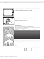
1
Operating Instructions SartoriusCombicsSeries CompleteScalesModelsCAW3P|CAW3S|CAH3 98648-018-49 Contents Contents Notes on Using this Manual Warnings and Safety Precautions Device Description IntendedUse OverviewofEquipment Installation Getting Started ConnectingPeripheralDevicesorAnotherPlatform ConnectinganISWeighingPlatformtoaCombics3 ConnectingPeripheralDevicesora2ndWeighing Platform:Combics3,ModelCAW3S|CAH3 InterfacePinAssignmentChartCOM1 ConnectingaPCviaInterfaceCOM1 InterfacePinAssignmentChartCOM2 ConnectingaPCviaInterfaceCOM2 InterfacePinAssignmentChartPS2 Scale Configuration ServiceMode EnteringAdjustmentandLinearizationWeights FunctionAllocationoftheAllocationfortheJKey forCalibration/Adjustment ExternalAdjustment InternalCalibration AdjustmentWithoutWeights FunctionAllocationoftheJKeyforLinearization andSetting/DeletingthePreload ExternalLinearization SettingthePreload ClearingthePreload Operating Design WeighingOperatingDesign MenuOperatingDesign Configuration SetupOverview(Parameters) Operation Weighing Calibration,Adjustment InternalAdjustmentforCAHModels SQminFunction DataIDCodes 2 OperatingInstructionsCombicsCompleteScales 3 4 6 6 7 8 12 12 13 14 15 16 17 18 19 21 21 32 38 39 43 43 46 47 50 51 52 52 58 59 63 76 76 86 90 91 94 Data Interfaces ConfiguringtheDataInterfaceasaCOMPort DataInputFormat DataOutputFormat ConfiguringtheDataInterfaceasaPrinterPort ConfiguringaPrintout GMP-compliantPrintouts SamplePrintouts ErrorCodes Care and Maintenance Service Repairs Cleaning SafetyInspection Disposal Specifications Balance Dimensions Accessories Documents List Sartorius Services Declaration of Conformity ECType-approvalcertificate TestCertificate PlatesandMarkings Appendix: Guide to Verification of Weighing Instruments Explosion-risk area Zone 2 or 22 Appendix: Passwords 96 99 101 102 106 107 108 109 115 117 117 117 117 118 119 120 123 125 128 128 129 131 132 133 137 140 145 NotesonUsingthisManual NotesonUsingthisManual t P leasereadthisentiremanualcarefullyandcompletelybeforeusingthedevice. t Readthesafetyprecautionscarefully. t Thismanualispartoftheproduct.Keepitinasafeandeasilyaccessible location. t Ifthemanualshouldbelostormisplaced,pleasecontactSartoriusfora replacementordownloadthelatestmanualfromourwebsite: www.sartorius-mechatronics.com Symbols and Signs Thefollowingsymbolsareusedinthismanual: 2 Warning symbol for various types of dangers. ThesesymbolsareexplainedinmoredetailinSection“SafetyInstructions.“ h Thissymbolindicatesusefulinformationandtips. Thissymbolindicatesnotesonuseinlegalmetrologywithinthescopeofvalidity ofCouncilDirectiveNo.90/384/EEC,replacedby2009/23/EC (modelsMS...-.CE...). e, 1, T T ..., Thisandsimilarsymbolsmeanthattherespectivekeyshouldbepressed. Thismeansthatthiskeymustbepressedmorethanonce. t y 1. 2. – Indicatesarequiredaction Describestheresultofanaction Ifaprocedurehasmultiplesteps... ...thestepsarenumberedconsecutively. Indicatesaniteminalist h Hotline/Technical Advice on Applications Phone: +49(0)40/67960444 Fax: +49(0)40/67960474 E-mail: [email protected] OperatingInstructionsCombicsCompleteScales 3 WarningsandSafetyPrecautions WarningsandSafetyPrecautions CombicsindicatorscomplywiththeEuropeanCouncilDirectivesaswellas internationalregulationsandstandardsforelectricalequipment,electromagnetic compatibility,andthestipulatedsafetyrequirements.Improperuseorhandlingcan, however,resultindamageand/orinjury. t R eadtheseoperatinginstructionscarefullybeforeuse. Thiswillpreventdamagetotheequipment. Theprotectiveconductormustnotbedisconnectedforanyreason.Useonly standardcablesthathaveprotectivegroundingconductors. 3 Ifthereisvisibledamagetotheequipmentorpowercord:unplugtheequipment andsecureitagainstfurtheruse. 3 Makeabsolutelysuretounplugtheindicatorfrompowerbeforeyouconnector 3 disconnectanyelectronicperipheraldevicestoorfromtheinterfaceport. ThedeviceshouldonlybeopenedbypersonneltrainedinaccordancewithSartorius guidelines. 3 Ifyouuseelectricalequipmentininstallationsandunderambientconditions requiringhighersafetystandards,youmustcomplywiththeprovisionsasspecified intheapplicableregulationsforinstallationinyourcountry. 3 Theoperatorshallberesponsibleforanymodificationstotheequipmentandfor 3 anyconnectionsofcablesorequipmentnotsuppliedbySartoriusandmustcheck and,ifnecessary,correctthesemodificationsandconnections. InformationonoperationalqualityisavailableuponrequestfromSartorius(inline withnormspertainingtoimmunity). Donotexposetheequipmenttoaggressivechemicalvaporsortounnecessarily extremetemperatures,moisture,shocks,orvibration. 3 Onlycleanthedeviceasstipulatedinthecleaninginstructions:Refertothe “CareandMaintenance“chapter. 3 Thedisplayvaluecanbeaffectedbyextremeelectromagneticinfluences.Oncethe 3 disturbancehasceased,theinstrumentcanbeusedagaininaccordancewithits intendedpurpose. Danger of Explosion! 4 1 Donotusethisequipmentinhazardousareas. OperatingInstructionsCombicsCompleteScales WarningsandSafetyPrecautions Installation Warningwhenusingpre-wiredRS-232connectingcables:RS-232cablespurchased 3 fromothermanufacturersoftenhavepinassignmentsthatareincompatiblewith Sartoriusproducts.Besuretocheckthepinassignmentsagainstthechartinthis manualbeforeconnectingthecable,anddisconnectanylinesidentifieddifferently fromthosespecifiedbySartorius. ConnectonlySartoriusaccessoriesandoptions,astheseareoptimallydesignedfor usewithyourdevice.Therefore,donotuseanyproprietarysolutions.Theoperator shallbesolelyresponsibleforinstallationandtestingofanymodificationsto Sartoriusequipment,includingconnectionofcablesorequipmentnotsupplied bySartorius.Informationonoperationalquality(inlinewithnormspertainingto immunity)isavailableonrequest. 3 t Ifyouhaveanyproblemswithyourdevice,contactyourlocalSartoriusoffice, dealerorservicecenter. IP Protection Rating IPRating – – – – – – AllmodelsareratedtoIP44(withoptionL1:IP65) CAWxSmodelsareratedtoIP67. CAH1E*models:platformIP65,indicatorIP69K. CAH1G*models:platformIP67,indicatorIP69K. CAWxSmodelsareratedtoIP69Kwiththe“I69“option. Completescaleswithsecuredprotectivecapsmustbeinstalledandtestedbya certifiedtechnician. – Ifyouinstallaninterfaceportorbatteryconnectionaftersettingupyour indicator,keeptheprotectivecapinasafeplaceforfutureuse.Thecapprotects theinterfaceconnectorfromvapors,moistureanddustordirt. Use in Legal Metrology – W hentheindicatorisconnectedtoaweighingplatformandthisequipmentis tobeverified,ensurethattheapplicableregulationsregardingverificationare observed. – WhenconnectingSartoriusweighingplatforms,observethe“Guideto VerificationofWeighingInstruments“andtheDeclarationofConformitywith thelistofpermittedweighingranges. – Astickerwiththe“Sartorius“logowasaffixedtotheindicatorasacontrolseal followingverification.Thissealwillbeirreparablydamagedifyouattemptto removeit.Thiswillnullifytheverification‘svalidity.Inthiscase,re-verification wouldberequiredincompliancewithallrelevantnationalregulationsandlaws. OperatingInstructionsCombicsCompleteScales 5 DeviceDescription DeviceDescription Combicscompletescales: – Arerobustanddurable,thankstotheirstainlesssteelhousing – Areeasytocleananddisinfect – Areeasytooperate,thankstothefollowingfeatures: – Large,backlit,fullygraphicaldot-matrixdisplay – Largekeyswithpositiveclickaction – Canbeoperatedindependentlyoftheweighingplatformlocation – Havearangeofinterfacesforflexibleuse – Haveoptionalpasswordprotectionforoperatingparameters Combics3speedsupyourroutineprocedureswith: – Integratedprogramsforapplications(somecanbecombined): – Counting – NeutralMeasurement – Averaging(animalweighing) – Weighinginpercent – Checkweighing – Classification – Totalizing – Net-totalFormulation – Automaticinitializationwhenthescaleisswitchedon – Fastresponsetimes – Automatictaringwhenaloadisplacedontheweighingplatform – Designationofweightvalueswithupto4linesofalphanumerictext – Canbecontrolledviatwoexternalcomputersusingvariousprotocols – BarcodescannerconnectionoptionforenteringtarevalueorIDs(6units) – Possibilitytoinputtarevaluesviathenumberblock – LEDformeasurementrangeidentification – Connectionoptionforasecondweighingplatform – AlibiMemory – Internalrechargeablebattery – Productdatamemory – Configurableprintout – FlexPrint Intended use TheCombics3isarobustcompletescalefordailyproductionandqualitycontrolin industrialapplications.Anyotherusebeyondthisisconsideredimproper. 6 OperatingInstructionsCombicsCompleteScales DeviceDescription General View of the Equipment 2 3 4 1 5 6 7 8 10 9 19 11 18 12 17 PS2 13 14 CAW3S | CAH3 11 1 Levelindicator 2 Loadplate 3 Levelingfeet Indicator 4 5 6 7 8 10digitkeypadforenteringalphanumericvalues LEDs(forcheckweighingandclassification) Display(fordetails,see“OperatingDesign“chapter) Additionalfunctionkeys(see“OperatingDesign“) Generalfunctionkeys:Zero,Tare,Switchfunction,Adjustment/ Calibration,Print/Dataoutput (see“OperatingDesign“) 9 Togglebetweenweighingplatforms(WP) 10On/Off Rear view of indicator: CAW3P 16 15 Platform 12 19 17 18 16 15 20 14 11 “UNICOM“ Optional: – RS-232|RS-485or422interface,e.g.for: – PCconnection – Printerconnection – DigitalI/O – 4to20mA – ProfibusDP – EthernetTCP/IP|ModBusTCP 12RS-232interface“COM1“ e.g.for: – PCconnection – Printerconnection – Digitalinput – Stoplightoutput 13“PS2“e.g.for: – Keyboardconnection – Barcodescannerconnection 14Powercordwithcountry-specificplug 15Inputformenuaccessswitch(standardorlegal-for-trademode) forWP1 16WeighingplatformWP1connection foranalogscales, optionalfor“xBPI“|“SBI“scales 17WeighingplatformWP2connection, optionalforanalogscalesor“xBPI“|“SBI“scales 18Inputformenuaccessswitch(standardorlegal-for-trademode) forWP2 19RS-232interface“COM2“ e.g.for: – PCconnection – Printerconnection 20Ventvalve:1.5Nm OperatingInstructionsCombicsCompleteScales 7 Installation Installation WhenaCombicsindicatorisorderedwithspecialequipment,thedesiredoptions comepre-loadedfromthefactory. Storage and Shipping Conditions Oncetheequipmenthasbeenremovedfromthepackaging,itmayloseaccuracyif 3 subjectedtostrongvibration. Iftheloadplateisliftedusingavacuumliftingpad,gloves,safetyshoesandsafety 3 gearmustbeworn.Riskofinjury! Thisworkmayonlybecarriedoutbyreliableandauthorizedpersonnel. Suspensionpointsareprovidedforweighingplatformswithanoverallsizeof 1+1morlarger.Donotstepundertheloadduringweighingplatform/loadplate transportorwhenlifting.Correspondingaccidentpreventionregulationsmustbe followed. Donotdamagetheclampboxesandloadreceptorsduringtransport. 3 – D onotexposetheequipmenttounnecessarilyextremetemperatures,moisture, shocks,blowsorvibration. – Permissiblestoragetemperature:–10°Cto+40°C Installation Location Avoidadverseinfluencesattheplaceofinstallation: – Extremetemperatures(operatingtemperature:–10°Cto+40°C) – Aggressivechemicalvapors – Extrememoisture(accordingtoIPprotectionclass) Unpacking For devices with a platform size of 60 x 80 cm or larger: t Protectivegearmustbeworn(safetyshoesandifrequired,gloves) t Alwaysliftonthesidewallswhenliftingortransportingtheweighingplatform. t A fterunpackingthedevice,checkitforanyvisibledamageasaresultofrough handlingduringshipment. y Ifyoudetectanydamage,proceedasdirectedinthechapterentitled“Careand Maintenance“under“SafetyInspection.“ t Savetheoriginalpackagingforanyfuturetransport. Unplugallconnectedcablesbeforepackingtheequipment. Checking Package Contents – – – – 8 Indicator Weighingplatform Operatinginstructions Options(specialaccessories)aslistedonthebillofdelivery OperatingInstructionsCombicsCompleteScales Installation CAH3 models: Remove transport locks t P lacetheweighingplatformatitsinstallationlocation,removethe weighingpan. t Removethetransportlock:Removescrew1 t Loosenscrew2. t Turnthemountingbracket180°andre-securescrew2. t Re-attachscrew1tothelever 3 Thetransportlockmustbere-installedbeforetransportingtheweighingplatform. Leveling the Weighing Platform Theweighingplatformmustbeexactlyleveltoensurereproducibleweighingresults everytime.Therefore,theweighingplatformmustalwaysbere-leveledafterithas beenmovedtoadifferentlocation. t Removetheweighingpan. t Loosenthelocknutsusingawrench(SW17). t U seaSW5Allenkeytoscrewthelevelingfeetin/out. Turningthelevelingfeetclockwiseliftstheweighingplatform, turningthelevelingfeetcounterclockwiselowerstheweighingplatform. OperatingInstructionsCombicsCompleteScales 9 Installation t A ligntheweighingplatformlevelingfeetsothatairbubbleiscenteredwithin thecircleofthelevelindicator. t Checktoensurethatallfourlevelingfeetrestsecurelyontheworksurface. y Eachofthelevelingfeetmustsupportanequalload. t R e-fastenthelocknutsafterleveling: Smallplatforms(1measuringcell)countertotheplatformframe, largeplatforms(4measuringcells)countertotheplatformfoot. t Placetheweighingpanonthescale. Operating Limits Youshouldnotexceedthehighestloadforweighingplatforms. Thehighestcapacityfortheweighingplatformisasfollowsdependingontheload used(center,side,one-sidedcornerload): Platform size 320+240 400+300 500+400 500+400P* 650+500S** 800+600P* 800+600S** 800+800 1000+800 1000+1000 1250+1000 1500+1250 1500+1500 2000+1500 Side 35 85 200 400 300 800 600 3000 3000 3000 3000 3000 3000 3000 Corner 20 45 100 200 150 400 300 1500 1500 1500 1500 1500 1500 1500 *Steel **Stainlesssteel For CAH* models 10 Center 50 130 300 600 450 1200 900 4500 4500 4500 4500 4500 4500 4500 OperatingInstructionsCombicsCompleteScales Platform size 400+300 560+450 800+600 Supported load (center) in kg 130 130 600 Installation Shock Resistance Theweighingplatformhasarobustdesign;however,fallingweighingsamples,side impactsandshocksshouldbeavoided.Theweighingplatformcanwithstandloads specifiedintheDINstandardIEC68Part2-27. Notes on Planning Superstructures 3 Superstructuresmustbecompletelyattachedbeforetheweighingplatformis connectedtothepower. Theweighingplatformisdesignedforsystemintegration.Scaledrawingsarethe basisfortheselectionoftherequiredsuperstructures.ThefixingofmodelCAH*IG* weighingplatformsshouldbecarriedoutusingtheYAS04ISfasteningkit. Movingorrotatingpartsontheweighingpanmustbedesignedsothatthe weighingresultsarenotinfluenced.Rotatingpartsshouldbecounterbalanced,for example. Theweighingpanmustbefreeonallsidessothatthereisnoconnectionbetween theweighingplatformandfixedpartsduetofallingpartsordirt.Cablesandhoses betweentheweighingplatformandotherdevicesmaynotexertanyforcesonthe weighingplatform.Thesecablesmaynottouchtheweighingpan. Whensettingupsystemsinhazardousareas(Zone2or22),anyrelevant specificationsshouldbeobserved,e.g.:EN60079-14. Thedesignshouldensurethatmovingpartsdonotcauseelectrostaticdischarges (e.g.rollerconveyors). Preload Range (Zero Set Range) Theweightofthesuperstructuresthatareattachedtotheweighingplatformis designatedasa“preload.“Thepreloadiselectronicallycompensatedforinthe weighingplatformsothatthefullweighingrangeremainsavailableandthus zeroingand/oradjustment(withexternalweights)ispossible. Greaterpreloadsreducetheweighingcapacity.Youmaynotfallbelowthefollowing weighingrangevalues: –ForCAH*E-16ED...andCAH*E-32ED...amin.20kgweighingrangemustbe maintained –ForCAH*E-64ED...andCAH*G-64FE...amin.35kgweighingrangemustbe maintained –ForCAH*G-150IG-HandCAH*G-300IG-Hamin.60kgweighingrangemustbe maintained Thepreloadmustalwaysbesetbeforeverification. Acclimatizing the Device Condensationcanformonthesurfacesofacolddevicewhenitisbroughtintoa substantiallywarmerarea. t Allowthedevicetoacclimatizeforabout2hoursatroomtemperature,leaving itunpluggedfromACpower. OperatingInstructionsCombicsCompleteScales 11 GettingStarted GettingStarted Steps 1.) Setuptheweighingplatformwiththeindicator. 2.) Leveltheweighingplatform 3.) Connectperipheraldevices,e.g.printertotheCOM1orUNICOMinterface: seeDataInterfaceschapterstartingonpage99 4.) ConnectingthedevicetoACpower 5.) Carryoutanalignment:foradjustment,seepage27,forlinearizationseepage24 Connecting Peripheral Devices or Another Weighing Platform AnanalogSartoriusplatform(CAPP,CAPS)oranISweighingplatformisconnected atthefactorytotheCombicsindicatorWP1input. 3 Theloadcellshouldbeconnectedbyacertifiedtechnicianwhohasreceived specializedtrainingfromSartorius.Anyinstallationworkthatdoesnotconform totheinstructionsinthismanualresultsinforfeitureofallclaimsunderthe manufacturer’swarranty. 3 3 Peripheraldevicesshouldbeconnectedbyacertifiedtechnicianwhohasreceived specializedtrainingfromSartorius.Anyinstallationworkthatdoesnotconform totheinstructionsinthismanualresultsinforfeitureofallclaimsunderthe manufacturer’swarranty. Disconnecttheequipmentfromthepowersupplybeforestartingconnectionwork. t Placecablesfromperipheraldevicesnexttotheindicator. CAW3S, CAH3 (IP69K) t OpeningtheCombicsindicator: Loosenthetencapnutsonthefrontpanel.Removethefrontpanel. Installing Connection and Interface Cables Thecablegland(IP69Kprotection)ispre-mountedontheindicator.Pleaseuse extremecautionwhenperforminganyworkontheequipmentthataffectsthis cablegland. Youmustuseatorque wrench.Thetorqueforthiscableglandis5 Nm. 3 12 Preparing Cables t Stripapprox.14cmfromtheendofthecable. t Shortentheshieldingtoapprox.2cmandpullbackovertheinsulation. t Stripapproximately5mmoftheinsulationfromthewiresoftheconnecting cableandaffixferrulestothewireends. OperatingInstructionsCombicsCompleteScales GettingStarted Attaching the Cable Entry Pleaseuseextremecautionwhenperforminganyworkontheequipmentthat affectsthiscablegland. Youmustuseatorque wrench. Thetorqueforthiscableglandis5 Nm. 3 1 5 4 t Removetheprotectivecapfromtheboreholeontheindicator. t Inserttheincludedcableglandthroughtheboreholeandsecurefromtheinside usingthelocknut(1). t Insertthecablethroughthecableglanduntiltheshielding(2)comesinto contactwiththeclamps(3).Tightenthescrew-downnut(4)untilthegasket(5) insertedbetweenthescrew-downnutandcableformsasmallbeadedrim. t Checktheshieldingandclamps. t Securelyconnectthewiresoftheconnectingcableinaccordancewiththe terminalassignments. t Afteryouclosethehousingagain,useapressuregaugetochecktheintegrityof theIP69Kprotection.Fordetails,contacttheSartoriusServiceCenter. 2 3 Connecting Cables t Insertallcablewiresthroughtheferritecase,windthemaroundtheferritecase andthenreinsertbackthroughtheferritecase. t Screwthewirestightlyintotheclamps. See the following pages for terminal pin allocation Refertothedatasheetoroperatinginstructionsofthe weighingplatformfordetailsontheassignmentofwire colors/signals.Ensureanylinesthatarenotassigned areinsulatedcorrectly. t Whenconnectingaloadreceptorthatuses4-conductortechnology(thecable oftheweighingplatformtobeconnectedonlyhas4lines),connectclamp pairs1and2(EXC+undSENSE+),and5and6(SENSE-undEXC-)withawire jumper. t Connecting an IS Weighing Platform to a Combics 3 YoucanconnectanISweighingplatformtoWP2. Features – ISweighingplatformsprocessweighingdataindependentlyoftheindicator. – Internaladjustmentoption – IS...-0CEmodels:haveaseparateapprovalnumber,printedonatagthatis affixedtothecable. – Pleaseobservetheconditionsdescribedinthemanualfortheweighingplatform youconnect. OperatingInstructionsCombicsCompleteScales 13 GettingStarted Connecting Peripheral Devices or a 2nd Weighing Platform: Combics 3, Model type CAW3S | CAH3 PS2 COM1 COM2 Digital PCB A8 COM1, COM2 and PS2 terminal assignments (applies to all PCBs) PS2 1 LOAD_PRINTER 11 Cleartosend(CTS) 21 5Vswitched 2 RESET_OUT 12 Dataterminalready(DTR) 22 PS/2_data 3 GND 13 Datainput(RXD) 23 PS/2_clock 4 GND 14 Dataoutput(TXD) 24 GND 5 5V_OUT 15 GND COM2 6 5Vswitched 16 UniversalIn 31 CTS_COM2 7 GND 17 Controloutput:“lower“ 32 DTR_COM2 8 GND 18 Controloutput:“equal“ 33 RXD_COM2 9 n.c. 19 Controloutput:“heavier“ 34 TXD_COM2 10 LINE_OUT 20 Controloutput:“set“ 35 GND 36 GND Weighing platform Interface 2 LED + Display Keypad A8 terminal assignments 1 EXC+ 2 SENSE+ 3 OUT+ 4 OUT- 5 SENSE- 6 EXC- Keys LED + Display PS2 COM1 COM2 A6/7 PS2 COM1 COM2 A20 Weighing platform Interface 1 Interface PCB for RS-232/485 for IS weighing platform (option A6/A7) A6/7 terminal assignments 1 CTS 2 DTR 3 RxD 4 TxD 5 GND 6 AdjustmentLock Keys LED + Display LED + Display Tastatur 11 TxD/RxD+ 12 TxD/RxD13 LINE_OUT 14 LINE_OUT 15 GND 16 GND Interface PCB for ADC 10.000e (option A20) A20 terminal assignments 1 EXC+ 2 SENSE+ 3 OUT+ 4 OUT5 SENSE6 EXCKeys LED + Display LED + Display Keypad 14 Bridgesupplyvoltage(+) Sense(+)forbridgesupplyvoltage Measuringvoltagepositive Measuringvoltagenegative Sense(-)forbridgesupplyvoltage Bridgesupplyvoltage(–) OperatingInstructionsCombicsCompleteScales PS2 COM1 COM2 A62/72 Weighing platform Interface 1 LED + Display Keypad GettingStarted Interface PCB for RS-232/485 for IS weighing platform (option A62/A72) Interface PCB A6/7 and A62/72 1 CTS 2 DTR 3 RxD 4 TxD 5 GND 6 AdjustmentLock Keys LED + Display 11 TxD/RxD+ 12 TxD/RxD13 LINE_OUT 14 LINE_OUT 15 GND 16 GND Interface Pin Assignment Chart COM1 Model type CAW3P (IP44 protection) COM1femaleconnectors: 25-pinD-Subminifemaleconnector(DB25S)withscrewlockhardwareforcable gland Recommendedinterfaceconnector: 25-pinD-Submini(DB25)withshieldedcableclampassemblyandshieldplate (Amptype826985-1C)andfasteningscrews(Amptype164868-1) COM1 pin assignments Pin 1: Shield Pin 2: Dataoutput(TxD) Pin 3: Datainput(RxD) Pin 4: GNO Pin 5: Cleartosend(CTS) Pin 6: Notassigned Pin 7: Internalground(GND) Pin 8: Internalground(GND) Pin 9: Notassigned Pin 10: Notassigned Pin 11: +12Vforprinter Pin 12: RES_OUT\ Pin 13: +5Vswitch Pin 14: Internalground(GND) Pin 15: Universalswitch Pin 16: Controloutput:“lower“ Pin 17: Controloutput:“equal“ Pin 18: Controloutput:“heavier“ Pin 19: Controloutput:“set“ Pin 20: Dataterminalready(DTR) Pin 21: Groundpowersupply(GND) Pin 22: Notassigned Pin 23: Notassigned Pin 24: Powersupply+15..25V(peripherals) Pin 25: +5V OperatingInstructionsCombicsCompleteScales 15 GettingStarted Connecting a PC via Interface COM1 UsethefollowingcablestoconnectaPCtotheindicatorinaccordancewiththe RS-232C/V24standard(max.cablelength15m): ModeltypeCAW3P: connectingcable7357312 ModeltypeCAW3S|CAH3: connectingcableYCC02-D09F6 RS232 Pin assignment PinassignmentsforthecablefromtheindicatortoanRS-232PCinterface(COM1). Indicator side PC side DSUBconnector 9-pinor 25-pin ModeltypeCAW3P 25-pinD-Submaleconnector 1 SgnGND 7 TxD 2 RxD 3 DTR 20 CTS 5 5GND 2RxD 3TxD 8CTS 4DTR ModeltypeCAW3S | CAH3 Opencableend DSUBconnector 9-pinor 25-pin SgnGND TxD RxD DTR CTS 5GND 2RxD 3TxD 8CTS 4DTR 16 15 14 13 12 11 OperatingInstructionsCombicsCompleteScales 7 GND 3 RxD 2 TxD 5 CTS 20DTR 7 GND 3 RxD 2 TxD 5 CTS 20DTR GettingStarted Interface Pin Assignment Chart COM2 Model type CAW3P (IP44 protection) COM1femaleconnectors: 25-pinD-Subminifemaleconnector(DB25S)withscrewlockhardwareforcable gland 5 1 9 6 Recommendedinterfaceconnector: 25-pinD-Submini(DB25)withshieldedcableclampassemblyandshieldplate (Amptype826985-1C)andfasteningscrews(Amptype164868-1) COM1 pin assignments Pin 1: Shield Pin 2: Dataoutput(TxD) Pin 3: Datainput(RxD) Pin 4: GNO Pin 5: Cleartosend(CTS) Pin 6: Notassigned Pin 7: Internalground(GND) Pin 8: Internalground(GND) Pin 9: Notassigned Pin 10: Notassigned Pin 11: +12Vforprinter Pin 12: RES_OUT\ Pin 13: +5Vswitch Pin 14: Internalground(GND) Pin 15: Universalswitch Pin 16: Controloutput:“lower“ Pin 17: Controloutput:“equal“ Pin 18: Controloutput:“heavier“ Pin 19: Controloutput:“set“ Pin 20: Dataterminalready(DTR) Pin 21: Groundpowersupply(GND) Pin 22: Notassigned Pin 23: Notassigned Pin 24: Powersupply+15..25V(peripherals) Pin 25: +5V OperatingInstructionsCombicsCompleteScales 17 GettingStarted Connecting a PC via Interface COM2 UsethefollowingcablestoconnectaPCtotheindicatorinaccordancewiththe RS-232C/V24standard(max.cablelength15m): ModeltypeCAW3P: connectingcable7357312 ModeltypeCAW3S|CAH3: connectingcableYCC02-D09F6 RS232 Pin assignment PinassignmentsforthecablefromtheindicatortoanRS-232PCinterface(COM1). Indicator side PC side DSUBconnector 9-pinor 25-pin ModeltypeCAW3P 25-pinD-Submaleconnector 1 SgnGND 7 TxD 2 RxD 3 DTR 20 CTS 5 5GND 2RxD 3TxD 8CTS 4DTR ModeltypeCAW3S | CAH3 Opencableend DSUBconnector 9-pinor 25-pin SgnGND TxD RxD DTR CTS 5GND 2RxD 3TxD 8CTS 4DTR 18 15 14 13 12 11 OperatingInstructionsCombicsCompleteScales 7 GND 3 RxD 2 TxD 5 CTS 20DTR 7 GND 3 RxD 2 TxD 5 CTS 20DTR Getting Started Interface Pin Assignment Chart PS2 6 4 2 5 Model type CAISL (IP44 protection) 3 PS2 female connector: 1 6-pin miniature socket PS2 (Mini-DIN) Recommended interface connector: 6-pin miniature socket PS2 with integrated shielded cable clamp assembly Pin assignment: Pin 1: Keyboard data (data interface cable) Pin 2: Not assigned Pin 3: Internal ground (GND) Pin 4: +5V switched Pin 5: Keyboard clock Pin 6: Not used Connecting a Bar Code Scanner Accessory YBR02CISL t Disconnect the indicator from AC power (unplug the AC adapter) For CAW3P models: t Connect the barcode scanner via PS/2. For CAW3S | CAH3 models: t Pin assignment, see “Connecting Peripheral Devices“ (implemented via the YCC02-BR02 connecting cable or as option M8) on page 14. NOTE: This equipment has been tested and found to comply with the limits pursuant to part 15 of FCC Rules. These limits are designed to provide reasonable protection against harmful interference. This equipment generates, uses and can radiate radio frequency energy and, if not installed and used in accordance with these instructions, may cause harmful interference to radio communications. For information on the specific limits and class of this equipment, please refer to the Declaration of Conformity. Depending on the particular class, you are either required or requested to correct the interference. If you have a Class A digital device, you need to comply with the FCC statement as follows: “Operation of this equipment in a residential area is likely to cause harmful interference in which case the user will be required to correct the interference at his own expense.“ Operating Instructions Combics Complete Scales 19 Getting Started Closing the Combics Indicator t Re-attach the front panel and secure it with the ten cap nuts ( 1Nm ). Connecting the Device to AC Power The indicator is powered through the pre-installed power cord. The power supply is integrated into the indicator. The device can be operated with a supply voltage of 100 V to 240 V. 3 The power connection must be made in accordance with the regulations applicable in your country. The printed voltage rating (see type label) must match the voltage in the place of installation. If the voltage specified on the label or the plug design of the AC adapter do not match the rating or standard you use, please contact your Sartorius office or dealer. t Check the voltage rating and plug design. t The device must be plugged into a properly installed wall outlet. Protection Class 1 Device t The device must be plugged into a properly installed wall outlet which has a protective grounding conductor (PE). Safety Precautions If you use an electrical outlet that does not have a protective grounding conductor, 3 ensure that an equivalent protective conductor is installed by a certified electrician (as specified in the applicable regulations for installation in your country). The protective effect must not be negated by using an extension cord without a protective grounding conductor. Before using for the first time, any superstructure parts must be completely installed. Avoid connecting the equipment to lines that have a heavy electrical load, e.g. compressors, large machinery, etc. 20 Warm-up Time To deliver exact results, the device must warm up for at least 30 minutes after connection to AC power. Only after this time will the device have reached the required operating temperature. Using a Verified Device in Legal Metrology Ensure that there is a warm-up time of at least 24 hours after connection to the power supply. Operating Instructions Combics Complete Scales Configuring Weighing Platforms Configuring Weighing Platforms Service-Mode Purpose The Service mode enables access to additional menu items in the Setup menu which are not displayed when the Service mode is not active. The most important calibration and adjustment work for the indicator and for the connected weighing platform can be carried out in the Service menu, e.g. ADC configuration. When the Service mode is active, an “S” is shown in the top right-hand corner of the display. To deactivate the Service mode, restart the indicator (turn the indicator off and back on again). Activating the Service Mode t Press e to turn on the device. y When turned on the scale is in an application program. t Enter the service password (see Appendix General User Password) and press M to confirm. y T he device in now is Service mode. An “S“ appears in the top right-hand corner of the display. t Press the “q“ soft key several times to select the “Device parameters“ line. t Press the “O“ soft key. y The “Device“ submenu will open. t S elect and open the corresponding submenu. Repeat this procedure until the desired menu item in the lowest menu level can be opened. t View or change the menu item (confirm with “l“) and use “o“ to return to the previous menu. t Press M or “oo“ to exit the Setup menu. Exiting Service Mode Turn the device off and then on again to return to the normal application mode. If you exit the Setup menu without changing settings by confirming with M or the “oo“ soft key, the Service mode will remain active. Press the M key to re-open the Setup menu. Operating Instructions Combics Complete Scales 21 ConfiguringWeighingPlatforms Overview of the Setup Menu in Service Mode o=Factorysetting x=User-definedsetting Servicepasswordentry Setup Applicationparameters,pleaserefertothe“BasicApplicationPrograms”manual Fnkey“SetupOverview(Parameters)“ Deviceparameters Info,seethe“SetupOverview(Parameters)“section Language,seethe“SetupOverview(Parameters)“section Setupaccesswithservicepassword Deviceparameters WP1 RS-2321) RS-4851) oIS-485 ADC-485 Internal ADCconfiguration(seethe“SetupMenuforADCConfiguration“section) Calibration/Adjustment CALkeyfunction oExt.cal./adj.;factory-def.wt. Ext.cal./adjust.;user-definedweight Ext.lineariz.;factory-def.wts Ext.lineariz.;user-def.wts Setpreload2) Deletepreload2) Keyblocked Cal./adj.sequence Cal.thenautoadjust oCal.thenmanualadjust isoCALfunction3) oOff Adjustmentprompt Activateexternaladjustment2) oActivated Deactivated Parameterforexternalweight Cal./adj.weight: Lin.weight1...4: Adjustwithoutweights2) Inputparameters Saveparameters SBIstandard SBIverifiable oIS-232 ADC-232 Geographicaldata2) 1)Equipmentversion:–thenblockedinternally 2)Notavailableondevicesverifiedforuseinlegalmetrology 3)OnlywhenoperatedwithSartoriusISweighingplatformsoranexternalADC 22 OperatingInstructionsCombicsCompleteScales Inputparameters Saveparameters Nominalload: Resolution: Sensitivity1…4: Yes oNo Geographicallatitude Altitude Gravitationalacceleration Yes oNo ConfiguringWeighingPlatforms DeviceParameters WP1 Internal Calibration/Adjustmentunit Grams/g Kilograms/kg Tons/t oPounds/lb Menuitems“Adaptfilter“-“Factorysettings:onlybal.func,“ seethe“SetupOverview(Parameters)“section Off COM-1(whentheWPisassignedtothisinterface) COM-2(whentheWPisassignedtothisinterface) UNICOM(onlyifavailable) WP2,seethe“SetupOverview(Parameters)“section RS-2321)similarto“Internal“menuforWP1 RS-4851)similarto“Internal“menuforWP1 oOff COM-1similartoWP1 COM-2similartoWP1 COM-1,seethe“SetupOverview(Parameters)“section COM-2,seethe“SetupOverview(Parameters)“section “ControlI/Oports“-“Terminaldata,“seethe“SetupOverview(Parameters)“section SQmin Alibimemory2) Clearalibimemory Alibimemoryperiod SQmininput Display GMPprint SQminWP1 SQminWP1 SQminWP2 SQminWP2 SQminWP3 SQminWP3 0.000kg 0.000kg 0.000kg No oYes oNo Yes Yes oNo Indays 90 1)Equipmentversion:–thensavedinternally 2)Onlyifalibimemoryisavailable(option) OperatingInstructionsCombicsCompleteScales 23 ConfiguringWeighingPlatforms Setup Menu for A/D Converter Configuration SetupaccessinServicemode WP1–Internal–ADCconfiguration Standardconfiguration Ranges Single-rangemode Scaleintervald Max.cap. Multi-intervalmode Scaleintervald Range1 Range2 Range3 Max.cap. Multiple-range mode Scaleintervald Range1 Range2 Range3 Max.cap. Availableunits User-definable/o Grams/g Kilograms/kg Carats/ct ... oVerifiable configuration Accuracy class Ranges ClassIII/IIII Single-rangemode D: E: Min.capacity: Max.cap.: Multi-intervalmode D: E: Min.capacity: Range1: Range2 Range3: Max.cap.: Multi-intervalmode D: E: Min.capacity: Range1: Range2 Range3: Max.cap.: Availableunits 24 Saveparameters Saveparameters OperatingInstructionsCombicsCompleteScales Yes oNo User-definable/o oGrams/g oKilograms/kg ... Yes oNo ConfiguringWeighingPlatforms Analog/Digital Converter (ADC) Purpose Adjusttheparametersoftheanalog/digitalconvertertotheconnectedloadcellor weighingplatform.AfterADCconfiguration,theADCinconnectionwiththeload sensorisdefinedasascale. OncetheADCconfigurationhasbeenlocked,theindicatorcannolongerbeused 3 toinfluenceweighingresults.Thescopeoffunctionsavailableintheweighing instrumentisdefinedbytheA/Dconverter.Weighingfunctionsthatcanbe activatedincludereadingweightvalues,taring,adjustment,readingthetarevalue, saving/deletingthetareentry. Setup Information – A DCconfigurationisonlypossiblewhenthemenuaccessswitchisopen. Re-closethemenuaccessswitchafterADCconfiguration. – BeforeADCconfiguration,youmustfirstsetwhetherornottheweighing platformwillbeusedasastandardorverifiableweighingplatform. – ADCconfigurationiscarriedoutintheServicemodeintheSetupmenuunder “WP1“forthefirstweighingplatformand“WP2“forthesecond. – EntriesmadeinADCconfigurationwillnotbeaffectedbyamenureset (returningthesetupparameterstotheirfactorysettings). Seealsotheoverviewinthe“SetupMenuforA/DConverterConfiguration“section. Setting Parameters for ADC Configuration Standard or Verifiable Configurations InADCconfiguration,youmustfirstselectwhethertheweighingplatformshould beconfiguredasastandardorverifiable(foruseinlegalmetrology)weighing platform. – Standardconfiguration“Standard“ – Verifiableconfiguration“Verifiable“ Selectusingthe“Q“or“q“softkey.Pressthe“O“softkeytoconfirmthesetting andopentheConfigurationmenu. Accuracy Class ThismenuitemisnotshownwhentheStandardconfigurationisactive.When theVerifiableconfigurationisactive(forweighingplatformsverifiedorverifiable foruseinlegalmetrology),onlyClassl/mcanbeselected.Activatethe “Accuracy class“menuitem,select“Class III/IIII“and confirmyourselectionusingthe“l“softkey. Ranges Thecapacityoftheweighingplatformcanbedividedintomultipleranges: – “ Single-range mode“: Theentireweighingrangeisdividedintoscaleintervalsonthebasisofthe lowestintervaldandthemaximumload. – “Multi-interval mode“: The“Multi-intervalmode”functiondividestheweighingcapacityintoas manyasfourranges,eachwithadifferentreadability.Correspondingchanges takeplaceautomatically.Oncethescalehasbeentared,thehighestpossible resolutionisavailableeveniftheweighingplatformisloadedwithahigher weight.Thisisonlypermittedintheaccuracyclassesl/mfortheverifiable configuration. – “Multiple-range mode“: Multiple-rangemodehastwoorthreeweighingranges.Whentherangelimit isexceeded,thescaleswitchesintothenexthighestweighingrange(lower resolution)andremainsthere.Thescalecanbereturnedtothelowerweighing range(higherresolution)onlybypressingthe(keyandthenunloadingthe scale. OperatingInstructionsCombicsCompleteScales 25 ConfiguringWeighingPlatforms Scale Interval d Verification Scale Interval e Minimum Capacity (Min. Cap.) Important Note: Maximum Capacity (Max. Cap.) Range 1, Range 2, Range 3 Available Units Saving Parameters 26 Selectthedesiredconfigurationusingthe“Q“or“q“softkey.Confirmyour selectionusingthe“O“key.Makeadditionalsettingsinthesubmenu:scaleinterval d/verificationscaleintervale,minimumload(Verifiableconfigurationonly), rangelimits(Multi-intervalorMultiplerangemodeonly)andmaximumcapacity. Confirmusingthe“l“softkeyorcancelusing“Esc.“ Scaleintervaldindicatestheresolutionoftheweighinginstrument. Thescaleintervaldcanbeenteredonlyinincrementsof1,2,5,10,20,etc. Whenusingverifiableorverifiedweighingplatforms,thescaleintervaldisthesame astheverificationscaleintervale. Theverificationscaleintervaleindicatestheresolutionoftheweighinginstrument inlegalmetrology.Theverificationscaleintervalecanbeenteredonlyin incrementsof1,2,5,10,20,etc.Forweighinginstrumentsofaccuracyclasslor m,e=d.Thisiswhythescaleintervalddoesnotneedtobeenteredseparately. When“Standardconfiguration”isused,thismenuitemisnotdisplayed. When“Standardconfiguration”isused,thismenuitemisnotdisplayed.The minimumloadoftheconnectedweighingplatformisenteredunderthismenuitem. Theminimumloadforscalesofaccuracyclasslis20eand10eforclassm. Thefunctionoftheminimumloadsettingistowarnoperatorsthatbelowthis limit,thesummationoftolerancesmightleadtosignificantmeasurementerrors.In Germany,forexample,initialweightsbelowtheminimumloadarenotallowed. Themaximumcapacityisthemaximumloadthatmaybeplacedontheweighing instrument.Whenheavierweightsareusedtheweighinginstrumentdisplays overload“H.”Thescaleintervalsoftheweighinginstrumentarecalculatedusing themaximumloadandthescaleintervald(e.g.max.capacity=15.000kg,smallest scaleintervald=0.005kgyields3000scaleintervals). Inlegalmetrologythetotalnumberofintervalsmustbenomorethan3000e,and whenusingmulti-intervalscalestheremustnotbemorethan3000eintervalsper range. Instandardoperation,asopposedtolegalmetrology,youcandefinea“Super Range”weighinginstrumentofover3000intervals.Theseparameters,however, maybeinfluencedbyphysicalrestrictions. Therangelimitsareenteredfortheindividualranges.Theaccuracychangeswhen theselimitsareexceeded.Thefollowingapplieswhenenteringlimits:range1 <range2<range3<maximumcapacity. Thismeansthattheweighingrangecanbedividedintoamaximumof4ranges. Theresolutionchangesatintervalsof1,2,5,10,20etc.,wherethelowest resolutionisthesmallestscaleintervalentered.Setrangesthatarenotrequiredfor usetozero. Withthisfunction,youcanmakeparticularweightunits(weightunitx,x=1,2) inaccessibleduringweighing.Availableunitsareindicatedbya*onthedisplay (morethanonecanbeselected). Toenableordisableaunit,selecttheunitbypressingthe“Q“or“q“softkey,and thenpressthe“l“softkey(togglefunction). TosavetheADCconfiguration,usethe“O“softkeytoselect“Yes“andconfirm withthe“l“softkey.Thedevicesoftwareisreset,andthescalereturnstothe normalweighingmode.Toexitthemenuwithoutsavingconfigurationchanges, pressthe“o“softkey. Oncetheseparametershavebeenconfigured,theA/Dconverterinconjunctionwith theloadcell(s)isdefinedasaweighinginstrument.TheA/Dconverter,inconjunctionwiththeweighingplatform,cannowbeusedlikeanystandardweighing platform.Inaddition,theweightunitmustbedefinedandtheweighingplatform adjusted(calibration,adjustmentandlinearizationmustbeperformed).Foradetailed descriptionoftheseprocedures,seethe“AdjustmentinServiceMode“section. OperatingInstructionsCombicsCompleteScales ConfiguringWeighingPlatforms Analog/Digital Converter (ADC) Configuration Condition Theweighingplatformmustalreadybeconnected. Open the Menu Access Switch Themenuaccessswitchislocatedonthebackoftheindicatorrightnexttothe weighingplatformconnection. t Removethecap. t Slidetheswitchtotheleft(=“open“position). Activating the Service Mode t See“ServiceMode“onpage17. Configuration t Selectweighingplatform“WP 1.“ t Ifthe“Internal“settingisnotalreadyactivated(markedby“o“),select thesettingusingthe“Q“or“q“softkeyandconfirmwith“O.“ y Themessage“Function active“appearsbriefly.The“WP1internal“ menuwillthenopen. t OpentheADC Configurationmenu. t Selectthedesiredconfigurationdatarecordusingthe“Q“or“q“softkey: “Standard“or“Verifiable“(verifiableconfiguration). Thedefaultsettingdependsonthedatarecord. t OpenthemenuforconfiguringA/Dconverterparameters.Inthisexample,the menuforADCconfigurationofaweighingplatformforuseinlegalmetrology isopened. If“Standard“wasselectedpreviously,thenthe“Accuracy class“isnotdisplayed. t Openthefirstmenuitem. Forastandardconfiguration,the“Ranges“menuitem,foraverifiable configuration,the“Accuracy class“menuitem. Whenthe“Verifiable”configurationisactive,alwaysselectthe“Accuracy class“menuitemfirst. t Setaccuracyclassl/m.The“o“symbolshouldmarkthesetting,ifrequired confirmusingthe“l“softkey. t Pressthe“o“softkeytoexitthemenuitem. t Openthe“Ranges“menuitem. OperatingInstructionsCombicsCompleteScales 27 ConfiguringWeighingPlatforms Intheexampleshownhere,“Single range mode“hasbeenselected (markedby“o“). t Toselectadifferentweighingrangeconfiguration,usethe“Q“or“q“softkey toselectthecorrespondinglineandopentheselectedmenuusingthe“O“soft key. y Theselectedweighingrangeconfigurationisnowactive.Whenyoureturn fromtheinputmenuforenteringtheweighingrangeparameters,thenew rangeconfigurationismarkedbya“o.“ Formoreinformationaboutrangeconfiguration,pleasesee“SettingParametersfor ADCConfiguration.“ Thedefaultvaluesdisplayeddependonthedatarecordloadedandmighthave tobechanged.Intheexampleshownhere,theA/Dconfigurationissetwitha “Verifiable”datarecordinsingle-rangemode. Single-range Mode t Selecttheindividualinputfieldsusingthe“Q“or“q“softkey. t F ornumericinput:usethe0...9keysandthe.key(decimalpoint). Makecorrectionsusingc. t Confirmusingthe“l“softkey. Ifotherparametersfollowtheonejustentered,thehighlightbaris automaticallypositionedonthenextinputfield. Tocancelnumbersentered:pressthe“ESC“softkey. t Usethe“o“softkeytogotothenextmenulevel. y Thiswillapplyallparameters. t PressM or“oo“toexittheSetupmenu. 0.002 Intheexampleshownhere,asingle-rangescalein“Verifiable”configuration withamaximumcapacityof6.000kgismodified;theverificationscaleinterval eischangedfrom0.001kgto0.002kg,inaccordancewiththemaximum permittedvalueof3000verificationscaleintervals.Pressthe“l“softkeyto confirmthechangedvalue. Thehighlightbarisautomaticallypositionedonthe“Min. cap.“field. Thefollowingvaluesapplyfortheminimumloadforverifiablescales: – Forclassl:Min.cap.=20e – Forclassm:Min.cap.=10e Averificationscaleintervalthatischanged,therefore,alsoaffectstheminimumload. Changingtheverificationscaleinterval“e“isautomaticallyappliedtothe“Min.cap.“ Youcanalsochangethisvaluemanually: Intheexample,theminimumcapacitymustbeincreasedto0.04kgforclassl. t Pressthefollowingkeysinsequence:0.040andconfirmusing the“l.“ y Thehighlightbarisautomaticallypositionedonthe“Max. cap.“field. t T hevalueforthemaximumcapacityisnotchanged.Forthisexample,the inputofparametersforsingle-rangemodeinthe“Verifiable”configurationis nowconcluded. 28 t Usethe“o“softkeytogotothenextmenulevel. OperatingInstructionsCombicsCompleteScales ConfiguringWeighingPlatforms Multi-interval Mode Theillustrationshowsanexampleoftheinputmenuopenedformulti-interval moderangeconfiguration.Thisexampleshowstheparametersforascalein “Verifiable”configuration,with2weighingrangesandamaximumcapacityof 6.000kg. – Range1:0…3.000kgwithe1=0.001kg – Range2:3.002…6.000kgwithe2=0.002kg t E ntertheverificationscaleintervalforRange1inthe“E“inputfield. Theminimumcapacityforaclasslscalemustbesetto0.02kg. t Usethe“o“softkeytogotothenextmenulevel. y Theactiverangeconfigurationismarkedwith“o.“ t Usethe“o“softkeytogobacktothe“Verifiable“menu. Selecting Units t U sethe“q“and“O“softkeytoopenthe“Available units“ menuitem. Thismenuletsyouenableordisabletheweightunitsavailableunder“Weight unit1,““Weightunit2“and“Weightunit3.“ t Selecttherespectiveunitusingthe“Q“or“q“softkeyandconfirmusingthe “l“softkey. Inmostcases,youwillnotneedtochangedefinedvalues. Availableweightunitsaremarkedbya*. Theweightunitusedforconfigurationofweighingrangescannotbeblocked. t Usethe“o“softkeytogobacktothe“Internal“menu. t Usethe“q“and“O“softkeytoopenthe“Calibration/ adjustment“menu. t Usethe“q“and“O“softkeytoopenthe“Calibration/ adjustment unit“menuitemtodefinetheweightunitfor calibrationandadjustment.Inmostcases,youwillnotneedtochangedefined values. y Allunitsaredisplayedinthemenuthatareactivatedin“Available units.“Thecurrentsettingismarkedbya“o.“ OperatingInstructionsCombicsCompleteScales 29 ConfiguringWeighingPlatforms t T ochangethecalibration/adjustmentunit,selecttheunitusingthe“Q“or“q“ softkeyandconfirmusingthe“l“softkey. t Usethe“o“softkeytogobacktothe“Internal“menu. t Usethe“Q“softkeytoselectthe“ADC configuration“menuitem. t Usethe“O“and“q“softkeytoselectthe“Save configuration data“menuitem. t T osavetheconfiguration,usethe“Q“softkeytoselect“Yes“andconfirm usingthe“l“softkey. y Themessage“Function activated“appearsbriefly. Theprogramthenreturnsautomaticallytotheregularweighingmode. Tonotsavetheconfiguration: t Pressthe“o“softkeytoexitthemenu. y Theprogramreturnstothenexthighermenulevel. Tonotsavedata: t Pressthe“o“softkey.TheprogramreturnstotheWP1:Internal. t Slidethemenuaccessswitchtotheright(=“closed“position)andreattachthe cap. y Thedeviceisnowinnormalweighingmode. 30 h OnceADCconfigurationhasbeencompleted,anadjustmentoftheweighing platform(calibration/adjustmentandlinearization)mustbecarriedout(see “Calibration/AdjustmentwithoutWeights“and“ExternalLinearization“). OperatingInstructionsCombicsCompleteScales ConfiguringWeighingPlatforms Thedisplaysdepictedinthenexttwoillustrationsontheleftshowdatafrom amulti-intervalscaleconfiguredasdescribedabove,orasimilarlyconfigured multiple-rangescale. IftheA/Dconverterwasconfiguredwitha“Verifiable”datarecord,thelinesfor displayofmetrologicaldata(lines1and2)showthedatavalidforuseinlegal metrology. Thecurrentrange(e.g.R1)isdisplayedtopleftundertheweighingpointfor multiple-rangescales. ADC Configuration with Load Cell(s) Connected Procedure: 1. O penthemenuaccessswitch,see“Analog/DigitalConverter(ADC) Configuration.“ 2. ActivatetheServicemode,see“ServiceMode.“ 3. ConfigureWP1,see“Analog/DigitalConverter(ADC)Configuration.“ 4. S etsingle-rangemode,forexample,see“Analog/DigitalConverter(ADC) Configuration.“ 5. Selecttheunits,see“Analog/DigitalConverter(ADC)Configuration.“ 6. Adjustwithoutweights,see“Adjustwithoutweights.“ 7. Set/Deletethepreload,see“SettingthePreload“and“DeletingthePreload.“ OperatingInstructionsCombicsCompleteScales 31 ConfiguringWeighingPlatforms Entering Geographical Data for Use in Legal Metrology Purpose Enteringgeographicaldataallowstheexternaladjustmentofweighingequipment ataplace(e.g.atthemanufacturerorvendor‘splaceofbusiness)thatisnotthe sameastheplaceofinstallation.Iftheweighingequipmentisadjustedattheplace ofinstallation,itisnotnecessarytoentergeographicaldata. Thesensitivityofweighingequipmentchangesdependingontheplaceof installationasitisdependentontheon-sitegravitationalforce–or,moreprecisely, ongravitationalacceleration.Savinggeographicaldatamakesitpossibletochange theplaceofinstallationoftheweighingequipmentafterexternaladjustmenthas beencarriedout. Theadjustmentofweighingequipmentisvalidattheplaceofinstallationand withinaspecifictolerancezone.At3000ethiszoneextends±100kmfromtheset geographicallatitudeand±200mfromthesetelevationabovesealevel. Installation Location in Germany Anexceptiontothisisthesettingfor“Germany(ZoneD):”Ifduringexternal adjustmentofweighingequipmentwithinGermanythegeographicaldata – Geographicallatitude:51.00degrees – 513melevationabovesealevel areentered,theweighingequipmentcanbeusedthroughoutGermany. Gravitationalaccelerationfor“Germany(ZoneD)”is9.810m/s2.Ondeliverythe geographicaldatafor“Germany(ZoneD)”areenteredintheoutputdevice. Itisrecommendedtousethegeographicaldatasettingsfor“Germany(ZoneD)” whenadjustinganddeliveringtheweighingequipmentwithinGermany. Enteringexactgeographicaldatawillleadtoahigherlevelofaccuracybutwillalso restrictthetolerancezone. Setup Information – Itisonlypossibletoentergeographicaldatawhenthemenuaccessswitchis open. – WhentheServicemodeisactive,geographicaldatacanbeenteredintheSetup menuunder“WP 1“forthefirstweighingplatformand“WP 2“forthe second.Settingsaremadeinthe“Calibration/adjustment: Geographical data: Input parameters“menu. – Youcanentereitherthe“latitude“(geographicallatitudeindegrees) and“altitude“(elevationinmabovesealevel)orthevaluefor gravitationalacceleration“gravity.“ Gravitationalaccelerationtakesprecedenceoverthegeographicallatitudeand elevationofthelocation:Ifithasbeenentered,inputfieldsforlatitudeand elevationshowthevalues“99999.99“and“9999999“respectively. Ifonlyelevationandlatitudehavebeenentered,“0000000“isdisplayed forgravitationalacceleration. h 32 Thenmakesurethatthegeographicaldatafortheadjustmentlocationhasbeen enteredcorrectly.Ifnoexternaladjustmentiscarriedout,enterthedataforthe installationlocation.Thedatacanbeobtainedfromtherelevantlandregistryor OrdnanceSurvey. OperatingInstructionsCombicsCompleteScales ConfiguringWeighingPlatforms Procedure t Removethecap. t Slidethemenuaccessswitchtotheleft(=“open“position). Ifthedeviceispartofaverifiedweighingfacility,thiswillonlybepossibleif theverificationsealisbroken.Theweighingequipmentmustthenbeverified again. t ActivatetheServicemode,see“ServiceMode.“ t Selectweighingplatform“WP 1“inthe“Device Parameters“ menuitem. t Ifthe“Internal“settingisnotalreadyactivated(markedby“o“),select thesettingusingthe“Q“or“q“softkeyandconfirmwith“O.“ y Themenuforthe“WP-1 INTERNAL“deviceparametersisdisplayed. t Usethe“Q“or“q“softkeytoselectandopenthe“CaCalibration/ adjustment“menuusing“O.“ t Usethe“Q“or“q“softkeytoselectanduse“O“toopenthe “Geographical data“menu. t Usethe“O“softkeytoconfirm“Input parameters.“ Entering Geographical Latitude and Elevation t Usethe“Q“or“q“softkeytoselectthecorrespondinginputfield. t Enterthenumberviathekeypadandconfirmusingthe“l“softkey. y Thenextinputfieldisselected. Inthisexample,thegeographicaldataareenteredfortherespectiveplatformasa valuepair“Latitude“and“Altitude.“Afterthisdatawassavedandthe scalereturnedtoweighingmode,thispairofvaluesisdisplayedagainthenexttime thedisplaymenuisopened.Theinputfieldforgravitationalaccelerationisempty. Inthisexample,thevalueforgravitationalaccelerationisenteredfortheplaceof installation.Thefields“Latitude“and“Altitude“areinvalid.Theset valueisthenre-displayedafteritissavedandtheinputmenuisre-opened.Ifyou exittheSetupmenuandthenopentheServicemode,thesetvalueforgravityisno longerdisplayed. OperatingInstructionsCombicsCompleteScales 33 ConfiguringWeighingPlatforms Entering Gravity t Usethe“Q“or“q“softkeytoselectthecorrespondinginputfield. t Entergravityinm/s2viathekeypadandconfirmusingthe“l“softkey. Permissiblevaluerange: 9.700000d<gravity2d<9.900000 Intheexampleshownhere,thevalueforgravityhasbeenchanged. Thenewvalue,9.810000m/s2appliestothesetting“Germany(ZoneD).” t Pressthe“o“softkeytoexittheInputmenu. t Usethe“Q“softkeytoselectthe“Save parameters“menuitem. t Usethe“Q“softkeytoselect“Yes“andusethe“l“softkeytoconfirm. y Themessage“Data stored“appearsbriefly. Theprogramthenreturnstothe“No“displaystatus. t PressM or“oo“toexittheSetupmenu. t Slidethemenuaccessswitchtotheright(=“closed“position)andreattachthe cap. y Thedisplaygoesoutandthedevicerestarts.Thenweighingmodeisactive. Adjusting Scales in Operating Mode Seealso“CalibrationandAdjustment“inthechaptercalled“Operation“ t OpentheDeviceparametersmenufortherespectiveweighingplatform, (e.g.“WP 1:INTERNAL“). – Openthe“Calibration/adjustment“submenu. – „CAL key function“menuitem: Setting“Ext. cal./adj.: factory-def. wt.“ (factorysetting). – „Cal/adj. sequence“menuitem: Setting“Cal. then manual adj.“(factorysetting). – „Activate ext. adj.“menuitem (notforaverifiableconfiguration): Setting“Activated“(factorysetting). TodisplaygeographicaldataintheDeviceparametersmenu,openthe “Operating parameters“submenu. Menuitem“Display geogr. data>On“. t Press(tounloadthescale. 34 OperatingInstructionsCombicsCompleteScales ConfiguringWeighingPlatforms t PressJtostartanexternaladjustment. y Thedisplay“C.EXT.D“appearsbriefly. Intheexample,thealtitudeandlatitudeoftheinstallationlocationarebeingentered. C.EXT.D C.EXT.DEF. y Thedisplay“Altitud“appearsbriefly. Altitud C.EXT.DEF. y Thealtitudeattheplaceofinstallationisdisplayedinmetersabovesealevel-here,the altitudefor“Germany(ZoneD).” t PressJtoconfirmthedisplayedvalueorpress(tocanceltheadjustment. y Thedisplay“Latitud“appearsbriefly. Latitud C.EXT.DEF. y Thegeographicallatitudeoftheplaceofinstallationisshownindegreesnorthor degreessouth-herethelatitudesettingfor“Germany(ZoneD).” t PressJtoconfirmthedisplayedvalueorpress(tocanceltheadjustment. y Youarepromptedtoplacetherequiredweightontheplatform(e.g.:5.0kg). Thesubsequentstepsforcompletingthecalibration/adjustmentaredescribedinthe chapterentitled“Operation”under“CalibrationandAdjustment.” OperatingInstructionsCombicsCompleteScales 35 ConfiguringWeighingPlatforms Ifgravityisbeingenteredinsteadofaltitudeandlatitude,then“Gravity“is displayedforabrieftimeafter“CAL.“ Theenteredvalueappearsinm/s2,hereforthe“Germany(ZoneD)“setting. t PressJtoconfirmthedisplayedvalueorpress(tocanceltheadjustment. y Y ouarepromptedtoplacetherequiredweightontheplatform(e.g.:5.0kg). Thesubsequentstepsforcompletingthecalibration/adjustmentaredescribed inthechapterentitled“Operation”under“CalibrationandAdjustment.“ t Slidethemenuaccessswitchtotheright(=“closed“position)andreattachthe cap. y Thedisplaygoesoutandthedevicerestarts.Thenweighingmodeisactive. Ifadjustmentiscarriedoutusingaverifiableconfigurationdatarecord,thelines fordisplayofmetrologicaldata(lines1and2)showthedatavalidforuseinlegal metrology,ifthemenuaccessswitchisclosed.Seealsothechapter“Operation“, “ConfigurationforUseinLegalMetrology.“ 36 OperatingInstructionsCombicsCompleteScales ConfiguringWeighingPlatforms Entering Adjustment and Linearization Weights Purpose Procedure Enteringadjustmentandlinearizationweights. Seealso“CalibrationandAdjustment“inthechaptercalled“Operation“. Removethecap. Slidethemenuaccessswitchtotheleft(=“open“position). ActivatetheServicemode,see“ServiceMode.“ Selectweighingplatform“WP 1“inthe“Device Parameters“ menuitem. t Ifthe“Internal“settingisnotalreadyactivated(markedby“o“),select thesettingusingthe“Q“or“q“softkeyandconfirmwith“O.“ y Themenuforthe“WP-1 INTERNAL“deviceparametersisdisplayed. t t t t t Usethe“Q“or“q“softkeytoselectandopenthe“Calibration/ adjustment“menuusing“O.“ t Usethe“Q“or“q“softkeytoselectanduse“O“toopenthe“Parameter for external weight“menu. t T hefirstmenuitem“Cal/adj. wt.:“(forselectingtheuser-defined calibrationweight),isalsoaccessiblewithoutactivatingtheServicemode. Thevaluesforthelinearizationweights“Lin.-wt. 1“to“Lin.-wt. 4“can,however,onlybechangedintheServicemode. y Thecurrentvaluesfortheuser-definedcalibrationweightandthe 4linearizationweightsaredisplayed. Inthisexample,thevaluefortheexternal,user-definedadjustmentweightis changedto6.000kg. t Press6.000andconfirmwiththe“l“softkey. y The“Lin.-wt. 1“inputfieldisselected. Inthisexample,thevalueforlinearizationweight1ischangedto1.500kg. t Press1.500andconfirmwiththe“l“softkey. y The“Lin.-wt. 2“inputfieldisselected. t E nterorchangealllinearizationweightsinsequenceasneeded. Ifyoudonotrequirealllinearizationpositions,enter“0.000“intheunused fieldstohidetheselinesinthedisplay.Confirmwiththe“l“softkeyaftereach entrytomovetothenextinputfield. Intheexampleshownhere,fourlinearizationweightshavebeenentered (1.5kg,3.0kg,4.5kgand6.0kg). Whenyouclosetheinputmenubypressingthe“o“softkey,theinputvalues aredirectlyapplied. t Slidethemenuaccessswitchtotheright(=“closed“position)andreattachthe cap. OperatingInstructionsCombicsCompleteScales 37 ConfiguringWeighingPlatforms Function Allocation of the allocation for the J Key for Calibration/Adjustment Purpose Procedure TheJkeyisusedforthecalibration/adjustmentfunction.Keysettingscanbe changedwhentheServicemodeisactivated: Removethecap. Slidethemenuaccessswitchtotheleft(=“open“position). ActivatetheServicemode,see“ServiceMode.“ Selectweighingplatform“WP 1“inthe“Device Parameters“ menuitem. t Ifthe“Internal“settingisnotalreadyactivated(markedby“o“),select thesettingusingthe“Q“or“q“softkeyandconfirmwith“O.“ y Themenuforthe“WP-1 INTERNAL“deviceparametersisdisplayed. t t t t t Usethe“Q“or“q“softkeytoselectandopenthe“Calibration/ adjustment“menuusing“O.“ t Usethe“O“softkeytoopenthe“Cal/adj. sequence“menu. t Usethe“Q“or“q“softkeytoselectthe “Cal. then manual adj.“menu(factorysetting)andconfirmwiththe“l“softkey. t Usethe“o“softkeytogotothenextmenulevel. t Usethe“O“softkeytoopenthe“Activate ext. adj.“menu. t Usethe“Q“or“q“softkeytoselectthe“Activated“menuitem (factorysetting).Notforaverifiableconfiguration. t Geographicaldataisnotdisplayedduringcalibration/adjustment(factory setting). TodisplaygeographicaldataintheDeviceparametersmenu,openthe “Operating parameters“submenu. Menuitem“Display geogr. data>On“. 38 OperatingInstructionsCombicsCompleteScales ConfiguringWeighingPlatforms t Usethe“O“softkeytoopentheCAL key function“menu. y The“CAL key function“submenuisdisplayed. t Usethe“Q“or“q“softkeytoselectthecorrespondingmenuitemandconfirm with“l.“ y Themenuitemismarkedbyacircle“o.“ ote N Thefunctionsthatcanbeconfiguredinthe“CAL key function“ submenudependsontheselectedweighingplatformanditsconfigurationdata. Functionsthatcannotbeaccessedarenotdisplayedintheselectionscreen. Important Note! Thefunctionsetinthe“CAL key function“menuiscarriedoutinthe normalweighingmodebecausewhenyouexittheSetupmenutheServicemodeis deactivated.Toperformthefunctiononadigitalweighingplatform(suchasan ISplatform),however,itmustbecarriedoutinServicemode. 12 C.EXT.D t T heprocedureisasfollows:afterselectingthedesiredfunctionandexiting theSetupmenu,reactivateServicemodeagainandthenexittheSetupmenu immediatelybypressingtheMkeyorthe“oo“softkey. y ThescaleisnowinServicemodewithoutthisbeingdisplayed. t TriggerthepreviouslysetfunctionusingtheJkey. y Thedisplayshows“S_CAl:“indicatingthatthescaleisinServicemode. t Thecorrespondingmenuitemcanbeselectedusingthe“Select“softkey andcarriedoutusingtheJkey. t Ifyoucancelthefunctionusingthe(keyorbyrestartingthescaleusing theekey,youwillexittheServicemode. C.EXT.DEF. External Calibration/Adjustment with Factory-Defined Weight (Default Weight) Configuration Ifnotalreadyselected(factorysetting,markedby“o“whenactive),selectthe “CAL key function:Ext. cal./adj.; factorydef. wt.“menuitem(externaladjustmentwithafactory-defined,standard weight). t Usethe“Q“or“q“softkeytoselectthismenuitemandconfirmwith“l.“ y Themenuitemismarkedbyacircle“o.“ Note: Themenuitems“Ext. cal./adj.; factory-def. wt.“ (externaladjustmentwithafactory-defined,standardweight),“Ext. cal./ adj.; user-defined wt.“(externaladjustmentwith auser-definedweight)and“Key blocked“canalsobeaccessedwithout activatingtheServicemode. OperatingInstructionsCombicsCompleteScales 39 ConfiguringWeighingPlatforms C.EXT.D t Pressetoturnoffthedevice. t Presseturnthedevicebackon. y TheSartoriuslogoisdisplayedbriefly,afterwhichthedeviceisinnormal weighingmode. t Press(tounloadandzerothescale. t PressJtostarttheexternaladjustment. y Thedisplay“C.EXT.D“appearsbriefly. Note Ifthedisplayofgeographicaldata(elevationandlatitudeorgravity)isactivated, thisdataisdisplayedandconfirmedeachwithapressoftheJkey(youcan cancelthecalibration/adjustmentprocessusingthe(key). Seealso“EnteringGeographicalDataforUseinLegalMetrology“inthischapter. C.EXT.DEF. Procedure y T hetargetvalueoftherequiredadjustmentweight(5.000kgintheexample)is displayedasanegativevalue. t Placetherequiredadjustmentweightontheplatform. Note Ifthecalibration/adjustmentsequenceissettoautomatic(“Calibration/ adjustment:Cal./adj. sequence:Cal., then auto adjust“menu,see“FunctionAllocationoftheallocationoftheJKeyfor Calibration/Adjustment“)andtheadjustmentweightconsistsofseveralpieces,then theyshouldbeplacedontheplatforminseriesatshortintervals. Whentheweighinginstrumenthasstabilized,theweightonthescaleisaccepted asthecalibrationweightafterapredefinedinterval,andtheweighinginstrumentis calibrated/adjustedwiththisweight. Thedifferencesincethemostrecentspanadjustmentisnotdisplayed;thisvalueis outputonlyonGMP-compliantprintouts. y A fterabriefpause,thedifferencesincethelastspanadjustmentisdisplayed (calibration). Note Thisdisplayonlyappearsforthe“Cal. then manual adj.“ setting(seepreviousnote).If“Cal. then auto adj.“isactive,the calibration/adjustmentprocedurecannotbecancelled. Tostoptheprocedureaftercalibrationandbeforeadjustmenttakesplace,pressthe (key(onlyif“Cal. then manual adj.“isactive). t P ressJtoadjustthescale(onlyif“Cal. then manual adj.“ isactive). y Attheconclusionofthecalibrationprocedure,thecalibrationweightis displayedasapositivevalue. 40 OperatingInstructionsCombicsCompleteScales -------------------14.01.2010 13:50 Type CAW3P1-6DC-LCE Ser.no. 12345678 Vers.no. 1.02.101110 BVers. 01-63-02 -------------------External calibration Nom. + 5.000 kg Diff. + 0.010 kg External adjustment Diff. + 0.000 kg -------------------14.01.2010 13:52 Name: -------------------- ConfiguringWeighingPlatforms Whencalibration/adjustmentiscomplete,theGMP-compliantprintoutshownon theleftisgenerated.Iftheadjustmentprocedureiscanceled(onlycalibrationis performed),thelasttwolines,“Externalcalibration”and“Diff.+0.000kg”arenot printed. t t t y Unloadthescale. Pressetoturnoffthedevice. Presseturnthedevicebackon. TheSartoriuslogoisdisplayedbriefly,afterwhichthedeviceisinnormal weighingmode. Ifaseriousoperatorerrorshouldoccurduringcalibration(forexample,ifthemenu setting“Cal. then auto adj.“isactiveandthewrongcalibration weightisplacedonthescale),thescalemightcompletelyfailtostabilize,which meansitcannotshowazeropoint. Inthiscase,selectthe“Adjust without weights“menuandsetthe meansensitivityofthestrain-gaugeweighingbeamto2.0mV/V. Thenre-adjustthescale. Seealso“Adjustwithoutweights.“ 3 Thezeropointisonlydisplayedforaverifiedscalewithd=e. External Calibration/Adjustment with a User-Defined Weight Configuration Selectthe“CAL key function:Ext. cal./adj.; userdef. wt.“menuitem(externaladjustmentusingauser-definedweight). Note: Themenuitems“Ext. cal./adj.; factory-def. wt.“ (externaladjustmentwithafactory-defined,standardweight),“Ext. cal./ adj.; user-defined wt.“(externaladjustmentwithauser-defined weight)and“Key blocked“canalsobeaccessedwithoutactivatingthe Servicemode. t Usethe“Q“or“q“softkeytoselectthismenuitemandconfirmwith“l.“ y Themenuitemismarkedassetbyacircle“o.“ t Enterthetargetvalueoftheadjustmentweightinthe“Calibration/ adjustment“menuunder“Parameter for external weight“inthe“Cal/adj. wt“inputfield. OperatingInstructionsCombicsCompleteScales 41 Configuring Weighing Platforms t Press e to turn off the device. t Press e turn the device back on. y The Sartorius logo is displayed briefly, after which the device is in normal weighing mode. t Press ( to unload and zero the scale. t Press J to start the external adjustment. y The display “C.EXT.U“ appears briefly. C.EXT.U C.EXT.USE. Note If the display of geographical data (elevation and latitude or gravity) is activated, this data is displayed and confirmed each with a press of the J key (you can cancel the calibration/adjustment process using the ( key). See also “Entering Geographical Data for Use in Legal Metrology“ in this chapter. Procedure t P ress J to confirm the displayed value or press ( to cancel the adjustment. y The target value of the required adjustment weight (6.000 kg in the example) is displayed as a negative value. t Place the required adjustment weight on the platform. If the calibration/adjustment sequence is set to “Cal. then auto adjust”, refer to the note under “External Calibration/Adjustment with Factory-Defined Weight (Default Weight).” y A fter a brief pause, the difference since the last span adjustment is displayed (calibration). t If you only want to perform a calibration, press the ( key to cancel the calibration/adjustment procedure. t Press J to adjust the scale. y A t the conclusion of the calibration procedure, the calibration weight is displayed as a positive value. -------------------14.01.2010 13:50 Type CAW3P1-6DC-LCE Ser.no. 12345678 Vers.no. 1.02.101110 BVers. 01-63-02 -------------------External calibration Nom. + 6.000 kg Diff. + 0.010 kg External adjustment Diff. + 0.000 kg -------------------14.01.2010 13:52 Name: When calibration/adjustment is complete, the GMP-compliant printout shown on the left is generated. If the adjustment procedure is canceled (only calibration is performed), the last two lines, “External calibration” and “Diff. + 0.000 kg” are not printed. t Unload the scale. t Press e to turn off the device. t Press e turn the device back on. y The Sartorius logo is displayed briefly, after which the device is in normal weighing mode. -------------------- 42 Operating Instructions Combics Complete Scales Configuring Weighing Platforms If a serious operator error should occur during calibration (for example, if the menu setting “Cal. then auto adj.“ is active and the wrong calibration weight is placed on the scale), the scale might completely fail to stabilize, which means it cannot show a zero point. In this case, select the “Adjust without weights“ menu and set the mean sensitivity of the strain-gauge weighing beam to 2.0 mV/V. Then re-adjust the scale. See also “Adjust without weights.“ 3 Internal Calibration/Adjustment This function is available only if a digital weighing platform (for example, an IS platform) is connected to WP 1, either as a second weighing platform or as the only weighing platform without using the built-in A/D converter WP 1. The connection can be made both via the COM1, COM2 or UNICOM interface with a corresponding configuration as well as via the expansion PCBs for WP 1 or WP 2. This function is also accessible without activating the Service mode. Adjustment Without Weights Purpose In the Service menu, adjustment without weights can be carried out by entering the characteristic data of the load cells. 3 Adjustment without weights may not be carried out on weighing equipment used in legal metrology. Setup information – Adjustment without weights is only possible when the menu access switch is open in the Service mode. – The “Nominal load“ parameter must be entered in the “kg“ unit. – The “Resolution“ parameter must be entered in the “kg“ unit and must correspond to the scale interval “d“ entered for the ADC configuration. – The “Sensitivity“ parameter is entered in “mV/V“ (see the data sheet for the value). h These values are converted to internal quantities. Once the ADC configuration data have been stored (by selecting the “Save parameters“ menu item), these parameters can no longer be read. Operating Instructions Combics Complete Scales 43 Configuring Weighing Platforms Procedure t t t t Remove the cap. Slide the menu access switch to the left (= “open“ position). Activate the Service mode, see “Service Mode.“ Select weighing platform “WP 1“ in the “Device Parameters“ menu item. t If the “Internal“ setting is not already activated (marked by “o“), select the setting using the “Q“ or “q“ soft key and confirm with “O.“ y The menu for the “WP-1 INTERNAL“ device parameters is displayed. t Use the “Q“ or “q“ soft key to select and open the “Calibration/ adjustment“ menu using “O.“ t Use the “Q“ or “q“ soft key to select and use “O“ to open the “Adjust without weights“ menu. t Use the “O“ soft key to open the “Input parameters“ menu. y The Input menu is displayed. Enter the nominal capacity and resolution of the load cells in kg and the sensitivity of the load cells in mV/V in the corresponding input fields. The maximum capacity is usually less than the value to be entered in the “Adjust without weights“ menu for the nominal capacity of the load cell, as load cells carry additional weight (e.g., a weighing platform). 44 Operating Instructions Combics Complete Scales Configuring Weighing Platforms If the weighing platform has multiple load cells, multiply the nominal capacity accordingly. Example: The weighing platform has 4 load cells each at 50 kg. The nominal capacity is 4 x 50 kg = 200 kg. In the example shown here, the weighing platform consists of one load cell with a maximum capacity of 10 kg. t Press 10.00 and confirm with the “l“ soft key. y The “Resolution“ input field is selected. The smallest digit “d“ is entered in this field in “kg“. The value must correspond to the “D“ entry in “ADC configuration: Standard: Ranges: Single-range mode.“ In the example, this should be d = 0.002 kg. Press 0.002 and confirm with the “l“ soft key. The “Sensitivity 1“ input field is selected. If the weighing platform has multiple load cells, enter the sensitivity either under “Sensitivity 1“ … “Sensitivity 4“ as an individual value or – under “Sensitivity 1“ as an average value. If an average value is entered for all cells, or if fewer than 4 load cells are present, enter “0“ in the remaining fields. Range of permitted values: 0.01…5 mV/V. t y – t t y t t Press 1.944, e.g. to enter a sensitivity of 1.944 mV/V. Confirm using the “l“ soft key. The “Sensitivity 2“ input field is selected. Either enter a value or set all remaining input fields to “0.“ Confirm each using the “l“ soft key. t Press the “o“ soft key to exit the menu. t Use the “q“ soft key to select the “Save parameters“ submenu. t To save the configuration, select “Yes“ and confirm using the l soft key. In the first line of the display, the message “Data stored“ is shown briefly. Then the program then returns to the “No“ display status. t Use the “o“ to return to the next menu level. t Press M or “oo“ to exit the Setup menu. t Slide the menu access switch to the right (= “closed“ position) and reattach the cap. y The display goes out and the device restarts. Then weighing mode is active. Operating Instructions Combics Complete Scales 45 Configuring Weighing Platforms Function Allocation of the J Key for Linearization and Setting/ Deleting the Preload Purpose The J key is normally used for the calibration/adjustment function. The following additional functions can be allocated to the key when the Service mode is activated: – – – – – External linearization with default weights External linearization with entered linearization weights Internal linearization (for external IS platforms only) Set preload (not possible in Legal Metrology) Delete preload (not possible in Legal Metrology) Once linearization has been completed, or after a preload has been set or deleted the function of the J key must be reallocated back to its original function in the Setup menu, e.g. external calibration/adjustment with default weights. 3 Procedure t t t t t y t y t y Remove the cap. Slide the menu access switch to the left (= “open“ position). Activate the Service mode, see “Service Mode.“ Select weighing platform “WP 1“ in the “Device Parameters“ menu item. If the “Internal“ setting is not already activated (marked by “o“), select the setting using the “Q“ or “q“ soft key and confirm with “O.“ The menu for the “WP-1 INTERNAL“ device parameters is displayed. Use the “Q“ or “q“ soft key to select and open the “Calibration/ adjustment“ menu using “O.“ The “CAL key function“ submenu is displayed. Use the “Q“ or “q“ soft key to select the corresponding menu item and confirm with “l.“ The menu item is marked by a circle “o.“ ote N The functions that can be configured in the “CAL key function“ submenu depends on the selected weighing platform and its configuration data. Functions that cannot be accessed are not displayed in the selection screen. Note The function set in the “CAL key function“ menu is carried out in the normal weighing mode because when you exit the Setup menu the Service mode is deactivated. To perform the function on a digital weighing platform (such as an IS platform), however, it must be carried out in Service mode. t T he procedure is as follows: after selecting the desired function and exiting the Setup menu, reactivate Service mode again and then exit the Setup menu immediately by pressing the M key or the “oo“ soft key. y The scale is now in Service mode without this being displayed. t Trigger the previously set function using the J key. y The display shows “S_CAl:“ indicating that the scale is in Service mode. t The corresponding menu item can be selected using the “Select“ soft key and carried out using the J key. t If you cancel the function using the ( key or by restarting the scale using the e key, you will exit the Service mode. 46 Operating Instructions Combics Complete Scales Configuring Weighing Platforms External Linearization with the Factory-Defined Weight (Default Weights) Setup Information – T his function is accessible only if the software and the functionality of the connected weighing platform permit this operation. – External linearization when weighing in legal metrology is only possible when the menu access switch is open. – The J key must be assigned the “External linearization“ function, see “Function Allocation of the J Key for Linearization and Setting/Deleting the Preload.“ – Activating the display of geographical data has no effect on this function. Once linearization has been completed, the J key must be reallocated back to its original function in the Setup menu, e.g. external calibration/adjustment with default weights. 3 Procedure t F or scales used in legal metrology, slide the menu access switch to the left (= “open“ position). y The display goes out and the device restarts. Then weighing mode is active. t Press ( to unload and zero the scale. t Press J to start the external linearization. y The display “L.EXT.D“ appears briefly. Additional steps are explained in “External Linearization with User-Defined Weights.“ Operating Instructions Combics Complete Scales 47 ConfiguringWeighingPlatforms External Linearization with User-Defined Weights Setup Information Oncelinearizationhasbeencompleted,theJkeymustbereallocatedback toitsoriginalfunctionintheSetupmenu,e.g.externalcalibration/adjustmentwith defaultweights. 3 Configuration – T hisfunctionisaccessibleonlyifthesoftwareandthefunctionalityofthe connectedweighingplatformpermitthisoperation. – Externallinearizationwhenweighinginlegalmetrologyisonlypossiblewhen themenuaccessswitchisopen. – TheJkeymustbeassignedthe“Externallinearization“function, see“FunctionAllocationoftheJKeyforLinearizationandSetting/Deleting thePreload.“ – Activatingthedisplayofgeographicaldatahasnoeffectonthisfunction. t S etthelinearizationweights,see“EnteringAdjustmentandLinearization Weights.“ Procedure t Forscalesusedinlegalmetrology,slidethemenuaccessswitchtotheleft (=“open“position). y Thedisplaygoesoutandthedevicerestarts.Thenweighingmodeisactive. t Press(tounloadandzerothescale. t PressJtostarttheexternallinearization. y Thedisplay“L.EXT.U“appearsbriefly. y A fterapprox.2seconds,thetargetvalueforlinearizationweight1isshownas anegativevalueonthedisplay(inexampleshownhere,1.500kg). t Placetherequiredlinearizationweight1ontheplatform. t PressJtoapplylinearizationweight1orpress(tocancelthe linearizationfunction. y A fterashorttimethedifferencebetweenthemeasuredvalueandthetrue weightofthesamplewillbedisplayed. 48 OperatingInstructionsCombicsCompleteScales -------------------14.01.2010 13:00 Type CAW3P1-6DC-LCE Ser.no. 12345678 Vers.no. 1.02.101110 BVers. 01-63-02 -------------------Linearization Wt.1 + 1.500 kg Wt.2 + 3.000 kg Wt.3 + 4.000 kg Wt.4 + 6.000 kg completed -------------------14.01.2010 13:02 Name: Configuring Weighing Platforms t P ress J to apply linearization weight 1 or press ( to cancel the linearization function. y After the linearization weight 1 has been saved you will be prompted to place the second linearization weight on the weighing pan. t Repeat the procedure for all required linearization weights. y After the last linearization weight has been saved you will be prompted to remove any load from the weighing pan. t Remove all linearization weights from the weighing platform. y The zero point is applied automatically after a brief time. The indicator automatically switches to weighing operation. When linearization is complete, the GMP-compliant printout shown on the left is generated. t Slide the menu access switch to the right (= “closed“ position). -------------------- Operating Instructions Combics Complete Scales 49 Configuring Weighing Platforms Set preload Setup Information – S etting the preload when weighing in legal metrology is only possible when the menu access switch is open. – The J key must be assigned the “Set preload“ function, see “Function Allocation of the J Key for Linearization and Setting/Deleting the Preload.“ – Activating the display of geographical data has no effect on this function. Once the preload has been set, the J key must be reallocated back to its original function in the Setup menu, e.g. external calibration/adjustment with default weights. 3 Procedure t F or scales used in legal metrology, slide the menu access switch to the left (= “open“ position). t Press e turn the device back on. y The Sartorius logo is displayed briefly, after which the device is in normal weighing mode. t Press ( to unload and zero the scale. y Display after the scale has been zeroed. t Place the preload weight on the weighing platform. t Press J to start “Set preload.“ y The display “SET PREL“ appears briefly. -------------------14.01.2010 13:50 Type CAW3P1-6ED-LCE Ser.no. 12345678 Vers.no. 1.02.101110 BVers. 01-63-02 -------------------Set preload completed -------------------14.01.2010 13:52 Name: After a short period of time the preload will be applied and the indicator will automatically switch back to weighing mode. After the “Set Preload” operation has been completed, the scale is zeroed. W hen the “Set preload“ function is complete, the GMP-compliant printout shown on the left is generated. t Slide the menu access switch to the right (= “closed“ position). -------------------- 50 Operating Instructions Combics Complete Scales ConfiguringWeighingPlatforms Delete preload Setup Information 3 Procedure – Deletingthepreloadwhenweighinginlegalmetrologyisonlypossiblewhen themenuaccessswitchisopen. – TheJkeymustbeassignedthe“Deletepreload“function,see“Function AllocationoftheJ KeyforLinearizationandSetting/DeletingthePreload.“ – Activatingthedisplayofgeographicaldatahasnoeffectonthisfunction. Oncethepreloadhasbeendeleted,theJkeymustbereallocatedbacktoits originalfunctionintheSetupmenu,e.g.externalcalibration/adjustmentwith defaultweights. t F orscalesusedinlegalmetrology,slidethemenuaccessswitchtotheleft (=“open“position). t Presseturnthedevicebackon. y TheSartoriuslogoisdisplayedbriefly,afterwhichthedeviceisinnormal weighingmode. t Removethepreloadweightfromtheweighingplatform. y Thedisplayshowstheremovedpreloadweightasanegativevalue. t PressJtostart“Deletepreload.“ y Thedisplay“CLR PREL“appearsbriefly. Afterashortperiodoftimethepreloadwillbedeletedandtheindicatorwill automaticallyswitchbacktoweighingmode. Afterthe“DeletePreload”operationhasbeencompleted,thescaleiszeroed. -------------------14.01.2010 13:50 Type CAW3P1-6DC-LCE Ser.no. 12345678 Vers.no. 1.02.101110 BVers. 01-63-02 -------------------Delete preload completed -------------------14.01.2010 13:52 Name: Whendeletingthepreloadiscomplete,theGMP-compliantprintoutshownonthe leftisgenerated. t Slidethemenuaccessswitchtotheright(=“closed“position). -------------------- OperatingInstructionsCombicsCompleteScales 51 Operating Design Operating Design Weighing Mode Operating Design You can use the Combics 3 to record weight values from 1 to 3 weighing platforms, calculate and display weight values through application programs, and assign IDs to the samples weighed. Configure the indicator first, using the Setup menu for the desired application program (printer settings, etc.). Then you can begin weighing. When a key is pressed that does not have an active operating mode function, an acoustical signal (double beep) sounds and the message “——-—“ is displayed for e 2 seconds. The display then y returns to the previous screen n content. ( ) k Some keys have a second function, activated by pressing and holding the key for over 2 seconds. Whether a function is available depends on the indicator operating state and operating menu settings. On/Off key standby is displayed in Standby mode. If a second weighing platforms is connected, this key toggles the display between the two readouts. – Press briefly: Zero – Press briefly: cancels calibration/adjustment – Press longer than 2 seconds: displays the adjustment/configuration counter Tare the scale: press briefly. Displays the second weight unit or SQmin (depending on the settings, see “Operation,“ “SQmin Function“). J p Starts calibration or adjustment. K L Toggles unit between normal and 10-fold higher resolution. c 52 Labeled Keys – For printing: Press briefly. – Prints GMP footer: Press longer than 2 seconds. Toggles the display between gross value (net value plus tare) and net value (gross value minus tare). – – Quits an application or deletes an input character: Press the key less than 2 seconds. Deletes the entire input string: Press the key longer than 2 seconds. Operating Instructions Combics Complete Scales OperatingDesign D TogglestotheInfomode: Presslongerthan2seconds. R Productdatamemory: Savesinitializationanduserdata(productandtarevalues). Theproductdatamemorycanstoreover400productandtarevalues. M Opens/ExitstheSetupprogram 1,2,3 ....,0 a Entersnumbers,lettersandothercharacters. Togglesbetweennumericandalphabeticinput. Soft keys Thefunctionsofactivesoftkeysareindicatedbysymbolsandabbreviationsinthe lastlineonthedisplay. Abbreviationexamples: – ID:IDlist – DELETE:Deleteentry ID F5 F4 F3 F2 F1 Symbols used for soft key functions: oo:Returntoinitialstate o: Nexthighermenulevel O: Showitemsunderselectedentry Q: Scrollupintheinput/outputwindow q: Scrolldownintheinput/outputwindow l: Settheselectedmenuparameter Numeric Input via the Keypad t T oenternumbers(onedigitatatime): Press0,1,2…9 t Tosaveinput: pressthecorrespondingkey. Forexample,press)tosavemanualtareinput. Text Input via the Keypad t y t y t t y Presstheakey. “ABC“isdisplayed. Forexample,pressthe4key. Thecorrespondingletterisdisplayed.Theflashingcursormarksthefirstletter. Pressthekeyasmanytimesneededtoselectthedesiredletter. PresstheF1softkey(l)orwait2seconds. Theselectedletterappearsonthedisplay. OperatingInstructionsCombicsCompleteScales 53 OperatingDesign Entering Spaces via the Keypad t y t y t y Presstheakey. “ABC“isdisplayed. Pressthe0key. Thecorrespondingselectionisdisplayed.Theflashingcursormarksthespace. PresstheF1softkey(l)orwait2seconds. Thespaceappearsonthedisplay. Special Character Input via the Keypad Presstheakey. “ABC“isdisplayed. Pressthe1key. Thecorrespondingcharacterselectionisdisplayed.Theflashingcursormarks thefirstcharacter. t PresstheF1softkey(l)orwait2seconds. y Thespecialcharacterappearsonthedisplay. t y t y Deleting characters t Pressc. Deleting entire input string t PresstheF4softkey(ESC). Saving Input t Enteravalue. t Pressthecorrespondingsoftkey(e.g.1.IDtodefineanidentifier). 54 OperatingInstructionsCombicsCompleteScales Operating Design Saving Settings in Weighing Mode ou can specify the save type used in the Application Parameters Y Setup menu. By default, all application parameters saved (e. g., reference values) remain in memory and are available when – the device has been switched off and then on again – you return to the originally selected application from a second one (e. g., when you switch from Averaging back to Counting all parameters saved for Counting are available). t t y Applying the Tare Weight To save the weight on the weighing platform as a tare weight: Place the tare object on the weighing platform. Press ). The value is applied as the tare value. Input Through the Digital Control Port You can connect a remote hand switch or foot switch to the input control line, for use with all application programs. The following functions can be assigned in the Setup menu Device Parameters:Control I/O Ports:Universal Switch Key: – – – – – – – – Off Print key Print key >2 sec Tare key ISO test key Fn key function WP toggle key Combined zero/ tare function – – – – – – – Zeroing key On key CF key F1 function key Appl. toggle key 10x higher resolution key Net/gross value key Operating Instructions Combics Complete Scales 55 Operating Design Display in Weighing Mode Linesformetrologicaldata Bargraph Weighing Mode: Display of Measured and Calculated Values Info/Statusline The display is divided into several sections. Lineformeasuredvalues Textlines Softkeylabels Plusorminussign Stability Applicationsymbol Tarememory Calculatedvalues Unit Batterysymbol Lines for metrological data The following parameters are shown here: Max M aximum capacity (upper weighing range limit) of the active weighing platform Min Minimum capacity (lower weighing range limit) of the active weighing (verified models only) e V erification scale interval of the active weighing platform (verified models only) d Smallest display digit of the active weighing platform R1 R2 Display of the current weighing range of the active weighing platform (with multiple range scale connected) Symbols and Their Meaning b The Busy symbol appears when the scale is processing a function activated by pressing a key. + - The plus or minus sign of the weight or other measured value o Verified models only: Identifies “zero” as a weight value (after the scale or the active weighing platform has been zeroed) Measured Value Line/Calculated Values 56 5.23r The current weight value (on verified scales or platforms with e = d, the last digit is bordered for identification) 20 A calculated value when using an application program, such as Counting or Weighing in Percent Unit and Stability g The current weight unit (e.g. “g“) pcs Identifies additional characteristics (e.g. “pieces“ for the “Counting“ application) When the weighing system reaches stability, the weight unit or calculation unit is displayed here. Operating Instructions Combics Complete Scales Operating Design Data in Tare Memory, Calculated Value, Identification of the Active Weighing Platform when More Than One Platform is Used ! Identification of calculated values (values not used in legal metrology) B/G NET Indicates gross value or net value (data in tare memory) PT Indicates manual tare input (using a barcode scanner) when viewing tare information. WP1 Display of the active weighing platform when 2 platforms are connected. The display flashes for a ISO Cal adjustment prompt if WP 1 is an IS‑weighing platform. WP When the timer is active (Setup:Device Parameters: Operating Parameters:Timer), the symbol flashes to indicate that the set time has halfway expired. Application, Printing and Battery Symbols S Printing in progress T GMP-compliant printout active , Battery status: ‘Battery fully charged’ or ‘Battery empty’ Bar Graph The bar graph shows the percentage of the weighing platform’s capacity that is “used up” by the load on the scale (gross value). 0% Lower load limit 100% Upper load limit The following symbols indicate tolerance levels for checkweighing: Bar graph showing 10% intervals Minimum for “checkweighing“ Target value for “checkweighing“ Maximum for “checkweighing“ Application Symbols A Symbol for the Counting application Y Symbol for “checkweigher“ counting down to “zero“ L H W M B A D Symbols for the Totalizing, Checkweighing, Classification, Net-total Formulation, Weighing in Percent, Counting (with or without reference sample updating) and Neutral Measurement application programs. For details on the symbols, please see the chapters for the respective application programs in the manual. Text Lines The text lines show operator support information, such as IDs and user guidance prompts. Soft Key Line This line shows the abbreviations or symbols that indicate soft key functions. Operating Instructions Combics Complete Scales 57 Operating Design LEDs LEDs indicate – whether the weight exceeds tolerance limits for checkweighing – the weight value classification for the Classification application Error Codes – If a key is inactive, “-------” and/or “No function”” is displayed (2 sec.) and an acoustic signal (double- beep) is emitted – Temporary errors are displayed for 2 seconds in the measured value/result line via an error code (e .g., INF 09); fatal errors (e .g., ERR 101) are displayed continuously until cleared via a restart. Error codes are described in detail in “Data Interfaces“ in “Error Codes.“ Menu Operating Design Operating Example: Setup:Device parameters: WP 1:Internal:Adapt filter o Marks the current menu setting Configuring parameters: t Soft key “Q“ or “q“: Parameter settings t Soft key “l“: Confirm parameter t M or “oo“: Exit Setup menu Menu display Display Mode for Configuration and Information (Setup) The display is divided into three sections. Status line Input/output window Soft key labels Status Line Indicates the function of the current screen page. In the Setup program, this line shows the “path” to the data displayed. Input and Output Window For input and display of detailed information; e.g., for the selected application. Selected items are displayed inversely (white letters on a black background). Soft key labels See the description in this section. Saving Menu Settings The parameters selected in the menu remain saved when you switch to weighing mode or turn off the device. You can block access to the Device parameters menu by requiring a password to prevent unauthorized or accidental setting changes (see also “Setting up Password Protection“). 58 Operating Instructions Combics Complete Scales OperatingDesign Configuration YoucanconfiguretheindicatorbyselectingparametersintheSetupmenu. Thesearedividedintothefollowinggroups(menulevel1),menustructuresee sectionthe“SetupOverview(Parameters)“section – Application parameters – Fn key function – Device parameters – Info(device-specificinformation) – Language Whenusedinlegalmetrology,notallparameterscanbeaccessed.Theindicator onlydisplaysparametersthatcanbeselected. Factory-setparametersareidentifiedbyan“o”intheliststartingonthenextpage. Setting the Language Youcanchoosefromthefollowinglanguagesfordisplayinginformation: – Deutsch – English(factorysetting) – U.S. mode – Français – Italiano – Español Example:Selecting“U.S.Mode“forthelanguage t Pressetoturnonthedevice. t PressM. y Themenuappearsonthedisplay. t Pressthe“q“softkeyseveraltimestoselectthe“Language“line. t Pressthe“O“softkey. y Thelanguageselectionappearsonthedisplay. t Pressthe“Q“softkeytoselectthe“U.S. mode“line. OperatingInstructionsCombicsCompleteScales 59 Operating Design t Press the l soft key to save the setting. y The setting selection “o“ moves to “U.S. mode.“ t Press M or oo to exit the Setup menu. Setting up Password Protection t t y t Press e to turn on the device. Press M. The menu appears on the display. Press the “q“ soft key several times to select the “Device parameters“ line. t Press the “O“ soft key. t Press the “q“ soft key several times to select the “Password“ line. y The input line appears on the display. t Enter numbers and/or letters via the keypad, see “Numeric Input via the Keypad“ and “Letter Input via the Keypad.“ t Press the “l“ soft key to save the setting. t Press M or “oo“ to exit the Setup menu. 60 Operating Instructions Combics Complete Scales Operating Design Setting up Password Protection t t y t Press e to turn on the device. Press M. The menu appears on the display. Press the “q“ soft key several times to select the “Device parameters“ line. t Press the “O“ soft key. y The Access window appears on the display. t Enter the password via the keypad, see “Numeric Input via the Keypad“ and “Letter Input via the Keypad.“ t Press the “l“ soft key. y The device selection appears on the display. t Press the “q“ soft key several times to select the “Password“ line. y t t t The input line appears on the display. Press c several times to delete the password. Press the “l“ soft key to save the delete. If not yet saved, the process can be canceled using the “ESC“ soft key. Press M or “oo“ to exit the Setup menu. Operating Instructions Combics Complete Scales 61 Operating Design Printing Parameter Settings Example: Maximum 20 characters per line. -------------------12.01.2010 09:46 Type CAIS3 Ser.no 12345678 Vers. 1.02.101110 BVers. 01-63-02 -------------------SETUP DEVICE ------------------- WP 1 Internal WP 2 off COM1 Data communcations SBI Baud rate 1200 Baud Parity Odd Number of Stop bits 1 Stop bit Handshake mode Hardware 1-char Number of data bits 7 Bit Data output Printout printer 1 etc. 62 Operating Instructions Combics Complete Scales Operating Design Setup Overview (Parameters) o =Factory settings W =User-defined setting Setup Application parameters: Please refer to the “Basic Application Programs” manual Fn key function o Off Unit conversion SQMIN (only possible when the display has been turned on in the “Device parameters:SQMin“ menu item) Device parameters WP 1 RS-232 1) RS-485 1) o IS-485 ADC-485 Internal SBI standard SBI verifiable o IS-232 ADC-232 Calibration/Adjustment CAL key function o Ext. cal./adj.; factory-def. wt. Ext. cal./adj.; user-defined wt. Key blocked Cal./adj. sequence Cal. then auto adjust o Cal. then manual adjust isoCAL function 3) o Off Adjustment prompt Activate external adjustment 2) o Activated Deactivated Parameter for external weight Cal./adj. weight: Calibration/adjustment unit Grams /g Kilograms /kg Tons /t Pounds /lb Adapt filter Min. vibration o Normal vibration Strong vibration Extreme vibration Application filter o Final readout Filling mode Low filtering Without filtering Stability range 1/4 digit 1/2 digit 1 digit 2) o 2 digits 2) 4 digits 2) 8 digits 2) 1) Equipment version: – then blocked internally Not available on devices verified for use in legal metrology 3) Only when operated with Sartorius IS weighing platforms or an external ADC 2) Operating Instructions Combics Complete Scales 63 1) 2) Operating Design Device Parameters WP 1 Internal Stability delay Without delay o Short delay Average delay Long delay Taring 1) Without stability o After stability Autozero o On Off Weight unit 1 2) User-definable / o (factory setting: grams) 1) Grams /g o Kilograms / kg Carats / ct 1) Pounds / lb 1) Ounces / oz v) Troy ounces / ozt 1) Hong Kong taels / tlh 1) Singapore taels / tls 1) Taiwan taels / tlt 1) Grains / GN 1) Pennyweights / dwt 1) Milligrams / mg 1) Parts per pound / lb 1) Chinese taels / tlc 1) Mommes / mom 1) Austrian carats / K 1) Tola / tol 1) Baht / bat 1) Mesghal / MS 1) Tons / t lb / oz Display accuracy 1 o All digits One less for wt. change Index +1 1) Index +2 1) One less 1) Zero range 1 percent/max. cap. o 2 percent/max. cap. Zero at power on 2 percent/max. cap. 5 percent/max. cap. o 10 percent/max. cap. Tare/zero at power on: o On Off Only zero at power on Not available on devices verified for use in legal metrology Depends on weighing platform type 64 Operating Instructions Combics Complete Scales 1) 2) Operating Design Device Parameters WP 1 Internal Weight unit 2 2) User-definable / o (factory setting: grams) 1) o Grams / g Kilograms / kg Carats / ct 1) Pounds / lb 1) Ounces / oz 1) Troy ounces / ozt 1) Hong Kong taels / tlh 1) Singapore taels / tls 1) Taiwan taels / tlt 1) Grains / GN 1) Pennyweights / dwt 1) Milligrams / mg 1) Parts per pound / / lb 1) Chinese taels / tlc 1) Mommes / mom 1) Austrian carats / K 1) Tola / tol 1) Baht / bat 1) Mesghal / MS 1) Tons / t lb / oz Display accuracy 2 o All digits One less for wt. change Index +1 1) Index +2 1) One less 1) Factory settings: weighing parameters only Yes o No Not available on devices verified for use in legal metrology Depends on weighing platform type Operating Instructions Combics Complete Scales 65 Operating Design Device Parameters WP 1 Internal Weight unit 3 2) User-definable / o (factory setting: grams) 1) o Grams / g Kilograms / kg Carats / ct 1) Pounds / lb 1) Ounces / oz 1) Troy ounces / ozt 1) Hong Kong taels / tlh 1) Singapore taels / tls 1) Taiwan taels / tlt 1) Grains / GN 1) Pennyweights / dwt 1) Milligrams / mg 1) Parts per pound / lb 1) Chinese taels / tlc 1) Mommes / mom 1) Austrian carats / K 1) Tola / tol 1) Baht / bat 1) Mesghal / MS 1) Tons / t lb / oz Display accuracy 3 o All digits One less for wt. change Index +1 1) Index +2 1) One less 1) Factory settings: weighing parameters only Yes o No Device parameters Off COM 1 (when the WP is assigned to this interface) COM 2 (when the WP is assigned to this interface) UNICOM (when the WP is assigned to this interface) WP 2 RS-232 3) o ADC-232 similar to “Internal“ menu for WP 1 RS-485 3) o ADC-485 similar to “Internal“ menu for WP 1 o Off COM 1 similar to WP 1 COM 2 similar to WP 1 UNICOM similar to WP 1 1) Not available on devices verified for use in legal metrology Depends on weighing platform type 3) Equipment version 2) 66 Operating Instructions Combics Complete Scales 1) 2) Operating Design Device Parameters COM 1 o Off WP 3 Data communications o SBI Baud rate 150 baud 300 baud 600 baud o 1200 baud 2400 baud 4800 baud 9600 baud 19200 baud Parity Space 1) o Odd Even None 2) Number of stop bits o 1 stop bit 2 stop bits Handshake mode Software handshake o Hardware 1-char Number of data bits o 7 bits 8 bits Data output o RS-232 SBI standard (9600 baud) SBI verifiable (9600 baud) o IS-232 1) ADC-232 1) On request, without stability o On request, after stability Automatic, without stability o 1 display update 2 display updates 10 display updates 100 display updates On request, without stability o 1 display update 2 display updates 10 display updates 100 display updates Printout printer 1 Printout printer 2 Not with 8 data bits Not with 7 data bits Operating Instructions Combics Complete Scales 67 1) 2) Operating Design Device Parameters COM 1 Data communications o SBI XBPI RS-232 SMA Not with 8 data bits Not with 7 data bits 68 Operating Instructions Combics Complete Scales Line format Sign format Factory setting For raw data (16 characters) o For other apps. (22 characters) Do not output + sign o Output + sign Yes o No Baud rate 150 baud 300 baud 600 baud o 1200 baud 2400 baud 4800 baud 9600 baud 19200 baud Parity Space 1) Odd Even o None 2) Number of stop bits o 1 stop bit 2 stop bits Handshake mode Software handshake o Hardware 1-char Number of data bits o 8 bits 1) Operating Design Device Parameters COM 1 Printer 1 1) YDP20 Baud rate Parity Number of stop bits Handshake mode YDP14IS o Strip Label Universal Baud rate Parity Number of stop bits Handshake mode o Software handshake Hardware, 1-char Number of data bits o 8 bits o YDP14IS o Strip Label Label, manual form feed Printer 2 1) Similar to printer 1 o 1200 baud 2400 baud 4800 baud 9600 baud 19200 baud Space o Odd Even o 1 stop bit 2 stop bits Software handshake o Hardware 1-char 150 baud 300 baud 600 baud 1200 baud 2400 baud 4800 baud o 9600 baud 19200 baud Odd Even o None o 1 stop bit 2 stop bits Max. 2 printers can be configured Operating Instructions Combics Complete Scales 69 1) Operating Design Device Parameters COM 2 similar to COM 1 UNICOM (optional interface) o Off WP 3 o RS-232 SBI standard (9600 baud) SBI verifiable (9600 baud) o IS-232 1) ADC-232 1) RS-485 o IS-485 1) ADC-485 1) Data communications o SBI similar to COM 1 xBPI-232 similar to COM 1 xBPI-485 address 0 to 31 can be selected SMA similar to COM 1 Profibus address: 0 to 126 can be selected, factory setting: 126 Ethernet Printer 1 1) Similar to COM 1 Printer 2 1) Similar to COM 1 Analog output Analog output: value o Net value Gross value Analog Out: Error Signal o High level (20 mA) Low level (0/4 mA). When menu is open or during calibration (0/4 mA) on this interface. Analog output: mode o Zero to maximum capacity Minimum/Maximum values Analog Out: Data Output Min./Max. o Min. (0/4 mA) input in kg Max. (20 mA) input in kg Not with 8 data bits 70 Operating Instructions Combics Complete Scales Operating Design Device Parameters I/O control Input ports Level internal output ports o All active low All active high Bar code o Reference Tare ID1 Input Input without activating function External keyboard Config. printout Headers Line 1: Line 2: ID codes ID1: ID2: ID3: ID4: ID5: ID6: ISO/GLP/GMP printout o Off For several application results Date/time Once at stability o Off On FlexPrint o Off On Universal switch key Off p Print key p Print key - long ) Tare key o J ISO-Test key k Fn key n WP toggle key Comb. tare/zero function (zero if possible, otherwise tare.) ( Zero key e On key c CF key v F1 function key D Toggle between applications K 10x higher resolution key L Net/gross value key o Date with time Date only Operating Instructions Combics Complete Scales 71 1) 2) Operating Design Device Parameters Config. printout Printer 1 Indiv.: Printout f. app./weighing List <-> Selection Gross (G#) Space line Tare ------- Net (N) Form feed Space line Date/time Time GMP header GLP footer Transaction no. ID1…ID6 Tare 2 (T2/PT2) Header line 1 Header line 2 Scale ser. no. Product no. Product name Product ID1…ID4 (application-dependent values) Comp.: Printout after saving val. 2) Similar to individual Total: Printout after pressing CF 2) Similar to individual Printer 2 1) Similar to printer 1 Decimal separator o Period Comma Data records (e.g. alibi memory, product data memory) All data records o Specified quantity Printout factory setting Yes o No Number of printouts o 1 printout 2 printouts Max. 2 printers can be configured Only when “Totalizing“ and/or “Net total“ has been selected under “Application parameters:Application 3“ 72 Operating Instructions Combics Complete Scales Operating Design Device Parameters Operating parameters Acoustic signal o On Off Linked to the green LED Keypad Block key functions All keys unblocked All blocked except e Alphanumeric keys blocked Weighing platform switch disabled Zero key blocked Tare key blocked Fn key blocked ISO-Test key blocked Print key blocked 10X higher resolution key blocked Net/gross value key blocked CF key blocked Softkey 5 key blocked Softkey 4 key blocked Softkey 3 key blocked Softkey 2 key blocked Softkey 1 key blocked Application switch disabled Setup key blocked Mem key blocked Display Contrast Backlighting o On Auto shutoff acc. to. timer Model Automatic shutdown Auto-off acc. to. timer o No automatic shutoff Timer o 1 + 1 minute 2 + 2 minutes 5 + 5 minutes Main scale o WP 1 WP 2 WP 3 Display geogr. data Off o On Factory settings: operat. param. Yes o No 0 1 2 3 4 o 5 6 7 o 2 1 Operating Instructions Combics Complete Scales 73 74 Operating Design Device Parameters Clock Time: Date: Test I/O ports Set internal outputs Read internal inputs Int. input 1: Passwords Password: SQmin Display o No Yes GMP print o No Yes Alibi memory Alibi memory period In days Operating Instructions Combics Complete Scales Int. output 1 (Lighter) Int. output 2 (Equal) Int. output 3 (Heavier) Int. output 4 (Set) 0 0 0 0 0 90 Operating Design Setup 1) 2) Info Service Service date: Terminal Model: Serial no. Basic ID: Version no.: (application software version) 1. WP 1 Model 2): Version no.: (software version) Serial no. 2): Latitude: 1) Altitude: 1) Grav. acc.: 1) Access switch 2. WP 2, see WP 1 3. WP 3, see WP 1 FlexInfo ID--V.--- Date Time Transaction no. Language Deutsch o English U.S. mode Français Italiano Español Alibi memory Depending on configuration prior to verification: either latitude/altitude or gravitational acceleration Not displayed for internal ADC Operating Instructions Combics Complete Scales 75 Operation Operation Weighing This application is always available during operation. Features – Zeroing by pressing ( – Storing the weight on the platform as a tare by pressing ) – Tare container weight automatically – Use a barcode scanner to enter tare weight – Use the numeric keys 0 to enter a tare weight and press ) to save – Delete tare values using the c key and save using the ) key – Toggle the display using the k key between: – 1st and 2nd weight unit – SQmin – You can configure the k key function in the “Fn key“ Setup menu – 10-fold increased resolution using the K key – Weighing using up to three weighing platforms – Individual numeric ID codes for weight values – Print weight values: – Manually, by pressing p – GMP printout (see “Data Interfaces“) – Automatic printout – Automatic data output (see “Data Interfaces“) – Restore factory settings in the Setup menu: „Application parameters:Factory settings: only application:Yes“ Soft Key Functions ID Enter up to six ID codes for identifying results on the printout 1st ID Save the value entered as the first ID code. Preparation t Select Setup: Press M. t Select Application parameters: Press the “O“ soft key. t Select “Application 1 (basic settings)“: Press the “O“ soft key. t Confirm the “Weighing“ application: Press the “l“ and “o“ soft keys. t Select the “Min. load f. auto. taring/printout“ function: Press the “O“ soft key. t Confirm the “o 10 digits“ setting: Press the “l“ and “o“ soft keys. t Select the “Factory setting“ menu item: Press the “O“ soft key. t Confirm the “o No“ setting: Press the “l“ and “o“ soft keys. t To save settings and exit the Setup menu: Press the M key or the “oo“ soft key. 76 Operating Instructions Combics Complete Scales Operation Automatic Taring The first weight on the scale that exceeds the preset minimum capacity is stored in the tare memory at stability. The values for subsequent loads are stored as weight values. The scale returns to the initial state when the load on the scale is less than 50% of the minimum load. Operating Menu Setting: “Application parameters: Autotare 1st weight:Yes“ Minimum load for automatic taring and automatic printing To tare container weights automatically, you need to set a minimum load in the Setup menu, under: “Application parameters:Min. load f. auto. taring/printout:o 10 digits“ You can set the following for the minimum load: 1 digit (no minimum load) 2 digits 5 digits 10 digits 20 digits 50 digits 100 digits 200 digits 500 digits 1000 digits The “digits“ here refer to the scale intervals for the connected weighing platform. If the interval is 1 g and 1000 digits are required, the minimum load is 1000 g (1000 intervals). If the weighing platform interval is 5 g and the same number of digits as above are required, the minimum load is 5000 g. Once the minimum load has been exceeded, the weighing platform is tared automatically and/or an automatic printout is generated. Automatic Printing The first weight value that exceeds the minimum load is printed. If the menu item is also activated for automatic taring, it is only tared when the minimum load is exceeded. In this case, an automatic printout would only be generated when the second weight value exceeds the minimum load. Setting in the Setup Menu: “Device parameters:Config. printout:Once at stability:On“ Weighing using up to three weighing platforms Press the n key to toggle between three weighing platforms. Operating Instructions Combics Complete Scales 77 Operation Main scale: first platform displayed on start-up You can select the weighing platform to be displayed first when the device is turned on in the Setup menu: “Device parameters:Operating parameters:Main scale:oWP 1“ Press n to toggle the readout between platforms. 78 Using a barcode scanner to enter tare weight The tare weight of the container can be entered via a barcode scanner. Operating Menu Setting: “Device parameters:Bar code:oTare‑value“ The value is applied and saved automatically. The content of the tare memory can be displayed in Info mode by pressing the D key. Using a barcode scanner to enter application parameters Application parameters (reference value) can be entered via a barcode scanner. Operating Menu Setting: “Device parameters:Bar code:oReference‑value“ The value is applied and saved automatically. Using a barcode scanner to enter an identifier Identifiers can be entered via a barcode scanner. Operating Menu Setting: “Device parameters:Bar code:oID“ The value is applied and saved automatically. Scanning barcodes directly You can directly scan a barcode using the barcode scanner. Operating Menu Setting: “Device parameters:Bar code:oInput“ The barcode can contain the following codes: – “I“ for write identifier – “T“ for save tare memory – “R“ for write reference weight – “A“ for activate product data memory Examples: “I4Anton“ = write the character string to ID 4: Anton “TC1“ = write 1 Kg to the preset tare memory. “C“ = unit: Kilograms “B“ = grams “D“ = carat, etc. “RC0.0023“= write 0.0023 kg as the reference weight “A1“ = load product data memory 1 Operating Instructions Combics Complete Scales Operation Adjustment/Configuration counter for standard scales Purpose Automatic recording of changes to adjustment and weighing parameters using two independent counters. The values remain saved for the life of the component. t T o display both counters, press and hold the ( key for longer than 2 seconds. y The “Configuration counter“ is then shown in the weight display for 3 seconds (identified by a “P“). Then the “Adjustment counter“ is displayed for another 3 seconds (identified by a “C“). After 6 seconds, the information display turns off automatically. Adjustment Counter Features: – – – – – Configuration Counter Features: – – – – Counter limited to 9999 Counter at “C 0000“ for hardware commissioning Counter cannot be reset Counter is updated automatically when: linearization, calibration/adjustment/preload change is successful – user calibration, adjustment or linearization weight is changed – When the following parameters are changed: – Function J key – Zeroing range – Initial zero point range – The above parameters are reset to factory settings Counter limited to 9999 Counter at “P 0000“ for hardware commissioning Counter cannot be reset Counter is updated automatically when: – When the following parameters are changed: – Installation location – Application filter – Stability range – Taring – Auto zero – Weight unit 1 – Weight unit 2 – Weight unit 3 – The above parameters are reset to factory settings – Turning the application automatic taring on/off – Restore application parameters to factory settings Operating Instructions Combics Complete Scales 79 Operation Device Parameters Password Protection Access to device and application parameters can be password-protected against unauthorized changes in the Setup menu under “Device parameters: Password,“ see the “Setting up Password Protection“ section in the “Operating Design“ chapter. Acoustic Signal An acoustic signal (single beep for active, double beep for inactive keys) is emitted when you press a key. The acoustic signal can be turned on/off and linked to the green LED in the Setup menu under “Device parameters:Operating parameters:Acoustic signal.“ Keys Keys can be blocked/unblocked in the Setup menu under “Device parameters:Operating parameters:Keys.“ The following settings are available: – All keys unblocked (default setting) – All blocked except e and H – Alphanumeric keys blocked – n blocked – ( blocked – ) blocked – k blocked – J blocked – p blocked – K blocked – L blocked – c blocked – Soft key 1…5 blocked – D blocked – H blocked – c blocked Automatic Shutoff of Combics You can specify that the indicator will shut off after a set time has elapsed in the Setup menu under “Device parameters:Operating parameters:Automatic shutoff,“ Display Lighting The following settings can be made for display lighting in the Setup menu under “Device parameters:Operating parameters: Display:“ – Contrast – Backlighting – Model 80 Timer The timer used to turn the device and/or display lighting on/off can be set to 2, 4, or 10 minutes in the Setup menu under “Device parameters: Operating parameters:Timer.“ Operating Instructions Combics Complete Scales Operation Tare the scale by placing a container on the weighing platform t Press the e key to turn on the indicator. y The automatic self-test runs. When the weight readout is shown, the scale is ready to operate and automatically set to zero. With no load on the platform, you can zero the weighing platform at any time by pressing (. t Place empty container on the scale. y The container weight is displayed. t Press the ) key to tare the scale. Note: If the automatic tare function is enabled, you do not need to press the ) key. The tare weight is saved automatically when you place the container on the platform. t Wait until a zero value is displayed together with the “NET“ symbol (net weight). t Place sample on the platform. t Wait until the weight unit symbol is displayed (indicating stability). t Read the weight value. Operating Instructions Combics Complete Scales 81 Operation Weighing with numeric entry of tare value and printing the results. t Press the e key to turn on the indicator. y The automatic self-test runs. When the weight readout is shown, the scale is ready to operate and automatically set to zero. With no load on the platform, you can zero the weighing platform at any time by pressing (. t Press the .25 key to enter a known tare weight via the keypad (in this example, 0.25 kg). t Press the ) key to apply the tare weight. t Place the container with sample on the platform. t Read the results. t Press the L key to toggle the display to the net weight value. y The display shows the gross weight (in this example, 0.250 kg for the container plus 2.000 kg for the sample). 82 Operating Instructions Combics Complete Scales Operation t Press the L key to toggle back to the previous display. -------------------24.10.2010 10:09 Typ CAW3P1-12ED-L Vers. 1.02.101110 BVers. 01-63-02 -------------------EISENSCHMIDT GOETTINGEN Chargen-Nr. 123456 Kunde Schulze 24.10.2010 10:09 -------------------G# + 2.250 kg T + 0.000 kg PT2 + 0.250 kg N + 2.000 kg --------------------------------------24.10.2010 10:10 Name: -------------------- t Press the p key to print the results. y Start of GMP header (only if GMP-compliant printout is configured). End of GMP header Headers Identifiers Start of GMP footer (only if GMP-compliant printout is configured) End of GMP footer Operating Instructions Combics Complete Scales 83 Operation Weighing with variable tare values, printing results, deleting tare values t Presstheekeytoturnontheindicator. y Theautomaticself-testruns. Whentheweightreadoutisshown,thescaleisreadytooperateand automaticallysettozero.Withnoloadontheplatform,youcanzerothe weighingplatformatanytimebypressing(. t Placeemptycontaineronthescale. t Pressthe) keytotarethescale. Note:Iftheautomatictarefunctionisenabled,youdonotneedtopressthe )key.Thetareweightissavedautomaticallywhenyouplacethecontainer ontheplatform. t Waituntilazerovalueisdisplayedtogetherwiththe“NET“symbol(netweight). t Placeapackagedsampleinthecontainer. t Pressthe.25keytoentertheknowntareweightofthepackagevia thekeypad(inthisexample,0.25kg). t Pressthe) keytoapplythepackageweightthatwasentered. Bothtareweightsareaddedtogether. 84 OperatingInstructionsCombicsCompleteScales Operation t ReadtheNetweight. G# + 6.433 kg T + 4.183 kg PT2 + 0.250 kg N + 2.000 kg -------------------- t Pressthep keytoprinttheresults. G# + 6.433 kg T + 0.000 kg N + 6.433 kg -------------------- t Pressthep keytoprinttheresults. t Pressthe0key. t Pressthe) keytoapplytheenteredvalue. y Thetarevaluesaredeleted.Thegrossvalueappearsonthedisplay. OperatingInstructionsCombicsCompleteScales 85 Operation Calibration, Adjustment Purpose Perform calibration to determine the difference between the value displayed and the actual weight on the platform. Calibration does not entail making any changes within the weighing equipment. During adjustment, the difference between the measured value displayed and the true weight of a sample is corrected, or is reduced to an allowable level within maximum permissible error limits. Configuration for Use in Legal Metrology Configuration of the weighing instrument for use in legal metrology is set by a switch. The switch is located on the back of the weighing platform and covered by a protective cap. Using a verified scale in legal metrology in the EU: The Type-Approval Certificate for verified scales is only valid for non-automatic weighing instruments. For automatic operation with or without additional, integrated equipment, please follow the applicable national regulations for the installation location. Externally Connected IS Scales: Before use in legal metrology, the scale should be adjusted via the internal adjustment equipment at the installation location: see chapter “Configuring Weighing Platforms,“ section “Internal Adjustment.“ 3 The temperature range (°C) listed on the ID label should not be exceeded during operation. For Servicing: External adjustment for verified scales of accuracy class l – External adjustment is blocked in legal metrology (switch cover is sealed) – External adjustment is only possible by removing the seal. If the seal is broken, the validity of verification will become void and you must have your scale re-verified. Using a verified scale in legal metrology with internal adjustment equipment: t Before use in legal metrology, the “internal adjustment“ function should be carried out at the installation location: Opening the Menu Access Switch The menu access switch is located on the back of the indicator right next to the weighing platform connection. t Remove the cap. t Slide the switch to the left (= “open“ position, for use in legal metrology). PS2 86 h You can determine the position of the switch in the Setup menu under “Info:WP.“ Operating Instructions Combics Complete Scales Operation Features Which of the following features are available depends on the connected weighing platform. These features are configured in the Setup menu: – Internal adjustment for several CAH models – External adjustment blocked in verified weighing instruments – External adjustment with the default weight value or user-defined weight (not available on verified instruments) under “…Calibration/ adjustment:CAL key function.“ – Specify the weight for external calibration/adjustment under “…Calibration/adjustment:Parameter for external weight“ – Internal adjustment for IS weighing platforms (configure under “COM1:, COM2: or UNICOM:WP3“) – Block the J key to prevent the use of the functions described above under “…Calibration/adjustment:CAL key function.“ – Calibrate first; then adjust automatically or manually (not for verified weighing instruments) under “…Calibration/adjustment: Cal/adj. sequence.“ – For Sartorius IS weighing platforms only: Flashing WP symbol as adjustment prompt (if more than one weighing platform is connected, the platform number is also displayed) under “…Calibration/adjustment:CAL key function.“ – Block/Unblock external adjustment under “…Calibration/adjustment:Activate ext. adj..“ – Altitude and latitude or gravitational acceleration displayed after “Cal“ is displayed at the start of the calibration/adjustment process if these values are supported by the weighing platform under “Device parameters:Operating parameters: Display geogr. data.“ For each of these parameters, the term is displayed first (Altitude, Latitude or Gravity) for 1 second, and then the corresponding value is displayed continuously until you press J. Operating Instructions Combics Complete Scales 87 Operation External calibration and manual adjustment with default weights (weighing parameters: factory settings) Select Setup menu: Press the M key. S elect Device parameters: Press the “O“ soft key. Select weighing platform “WP 1,“ “WP 2:“ Press the “O“ soft key or Select interface “COM 1,“ “COM 2“ or “UNICOM“ (depending on the interface): Press the “O“ soft key. t Select weighing platform “WP 3:“ Press the “O“ soft key. Calibration/Adjustment CAL key function o Ext. cal./adj.; factory-def. wt. Ext. cal./adj.; user-defined wt. Key blocked Cal./adj. sequence Cal. then auto adj. o Cal. then manual adj. isoCAL function (for Sartorius IS weighing platforms only) o Off Adjustment prompt Activate ext. adj. o Activated Deactivated Parameter for external weight o = Factory setting Preparation t t t t t T o save settings and exit the Setup menu: Press the M key or the “oo“ soft key. Procedure t Zeroing the scale by pressing the ( key. 12 t Start calibration/adjustment using the J key. y The display “C.EXT.D“ appears for two seconds. C.EXT.D C.EXT.DEF. y You are prompted to place the required calibration/adjustment weight on the platform (e.g., 10 ,000 g). 88 Operating Instructions Combics Complete Scales Operation t Place the calibration/adjustment weight on the weighing platform. y The difference between the measured value and the true weight of the sample will be displayed with plus/minus signs. External calibration Nom. + 10000 g Diff. + 1 g y A printout will be generated if the adjustment is not carried out and the procedure is stopped by pressing the ( key. t Start adjustment via the J key (cancel calibration/adjustment via (). y The adjustment weight is displayed once adjustment is finished. -------------------24.10.2010 10:15 Type CAIS3 Vers.no. 1.02.101110 BVers. 01-63-02 -------------------External calibration Nom. + 10000 g Diff. + 1 g External adjustment Diff. + 0 g -------------------24.10.2010 10:15 Name: y A GMP-compliant printout is generated. -------------------- Operating Instructions Combics Complete Scales 89 Operation Internal adjustment for CAH Models... System Requirements – T he menu item “Intern. cal./adjust.“ is preset for scales with internal adjustment. – The scale housing has a built-in motorized adjustment weight. – The calibration/adjustment sequence is preset to manual adjustment in the “Calibration/adjustment:Cal/adj. sequence: Cal. with manual adjust.,“ see section “Function Allocation of the J Key for Calibration/Adjustment“ Example: Internal calibration and then adjustment (weighing parameters: factory settings for CAH... models) Procedure t Press the ( key to unload and zero the scale. t Press J to start the internal calibration. y The display “C.INTER“ appears while the internal adjustment weight is placed on the platform. C.INTER C.EXT.DEF. C.Inter y Then the display “CI“ appears. CI C.EXT.DEF. Just.-Intern y A fter a brief pause, the difference since the last span adjustment is displayed. t Press J to start internal adjustment or press ( to cancel the calibration/ adjustment. y W hen calibration/adjustment is complete, the GMP-compliant printout is generated. If the adjustment procedure is canceled (only calibration is performed), the last two lines, “Internal adjustment” and “Diff. + 0.000 kg” are not printed. y The device is now in normal weighing mode. 90 Operating Instructions Combics Complete Scales Operation SQmin Function Purpose To display the allowable minimum sample quantity “SQmin” (sample quantity minimum) in accordance with the United States Pharmacopoeia (USP). According to USP guidelines, the uncertainty of measurement may not exceed 0.1% of the sample quantity when substances are weighed with the highest degree of accuracy for volume determination. This additional function ensures that weighing results lie within defined tolerance limits corresponding to the requirements of your quality assurance system. System Requirements The scale must be set up by a service technician to be able to use the SQmin function. The technician will determine the permitted minimum sample quantity and set this on your balance using your QA system‘s guidelines. He will document this setting via a “Weighing module test as per USP“ certificate in which the measurements and min. sample quantity are logged. The SQmin function ensures that the weighing results correspond to USP guidelines. These SQmin settings cannot be changed by the user. Features – D isplaying the minimum sample quality: The value is displayed in the text line for 4 seconds after pressing the k key. – If the minimum sample quantity has not been reached: The ksymbol is displayed and weight values are marked with a “!“ in the printout. – GLP header: The minimum sample quantity entered for SQmin can be included on the printout. Operating Instructions Combics Complete Scales 91 Operation SQmin Operation Configuration in Service Mode TheSQminvaluecanonlybeenteredinServicemode. t Removethecap. t Slidethemenuaccessswitchtotheleft(=“open“position). Ifthedeviceispartofaverifiedweighingfacility,thiswillonlybepossibleifthe verificationsealisbroken.Theweighingequipmentmustthenbeverifiedagain. t ActivatetheServicemode,see“ServiceMode.“ t Inthe“Device parameters“menu,select“SQmin“andopen usingthe“O“softkey. t Select“SQmin input“usingthe“O“softkey. t Select“SQmin WP1“usingthe“O“softkey,enterthevalueviathekeypad (inthisexample0.100kg)andsaveusingthe“l“softkeyorcancelusing“ESC.“ t ThenenterthevaluesforWP2andWP3. t PressM or“oo“toexittheSetupmenu. t Slidethemenuaccessswitchtotheright(=“closed“position)andreattachthe cap. y Thedeviceisnowinnormalweighingmode. Configuration in Weighing Mode t Inthe“Device parameters“menu,select“SQmin“andopen usingthe“O“softkey. t Select“Display.“. t Openusingthe“O“softkey. t Confirmthefactorysetting“oYes“usingthe“l“softkey. t Pressthe“o“softkeyseveraltimestoswitchtothenexthighestmenu. TheSQmindisplaymustbeturnedontousetheSQminfunction. t Inthe“Fn key:SQmin display:“menu,selectusingthe“O“soft keyandconfirmusingthe“l“softkey. t PressM or“oo“toexittheSetupmenu. 92 OperatingInstructionsCombicsCompleteScales Operation Procedure t Placethecontainerforthesampleonthescaleandpressthe)keytotare. t Placethesampleonthescale. y Theminimumsamplequantityisnotreached(symbolk). t Pressthepkeytogeneratetheprintout. t Placeanothersampleonthescale. y Theminimumsamplequantityisexceeded(nosymbolk). t Pressthepkeytogeneratetheprintout. t B rieflypressthekkeytotogglebetweenthemeasuredvalueandSQmin value. y Thevaluefortheminimumsamplequantityisdisplayedforfourseconds. OperatingInstructionsCombicsCompleteScales 93 Operation Data ID Codes You can assign codes (such as product name, batch number, etc.) for identification of measured values in all application programs. Features – – – – – – – – – – – Assign up to six ID codes. Assign both a name and a value to each ID code. Displaying individual IDs: press the “ID“ soft key. The name is left-justified and the value is right-justified on the printout. If the entire code is too long for one line, additional lines are printed. Enter ID code names in Setup under: “Device parameters:Config. printout:ID codes.“ The name can have a max. of 20 characters. When entering the ID value, no more than 11 characters are displayed during input; however, all 20 characters are printed. Enter up to 21 characters for the value of the ID code. Press the “ID“ soft key to activate the input mode. Enter the first ID value directly through the numeric keypad. Press the “1st ID“ soft key to save the value. Individual characters of the ID can be deleted using the ( key. Complete ID code values can be deleted using the “Delete“ soft key. If both the name and value fields are empty, no ID code is printed. In the Setup menu, you can configure when and whether ID codes are printed (see included “Application Programs“ instructions, “Configuring Printouts“). Settings for individual ID codes Setup menu: “Device parameters:Config. printout: Factory settings for ID code names: ID1: “ID1“ ID2: “ID2“ ID3: “ID3“ ID4: “ID4“ ID5: “ID5“ ID6: “ID6“ There are no factory settings for ID code values. 94 Operating Instructions Combics Complete Scales Operation Using Individual ID Code Example Enter ID code names. “Batch no.“ and “Customer“ should be entered for ID 1 and ID 2. t Press the M key and select “Device parameters:Config. printout:ID codes.“ y The first line is selected. t P ress the a key to enter “Batch no.“ via the keypad, see also chapter “Operating Design,“ sections “Text Input via the Keypad“ and “Special Character Input via the Keypad.“ t Press the “l“ soft key to save the entry. t Press the “q“ soft key to select the second line. t Press the a key to enter “Customer“ via the keypad, see also “Operating Design,“ “Text Input via the Keypad.“ t Press the “l“ soft key to save the entry. t Press M or “oo“ to exit the Setup menu. Example Enter ID code values. The values “123456“ and “Smith“ should be entered for ID 1 and ID 2. t Press the “ID“ soft key. y The first line is selected. t P ress the key to enter “123456“ via the keypad, see also “Operating Design,“ “Number Input via the Keypad.“ t Press the “l“ soft key to save the entry. t Press the “q“ soft key to select the second line. t Press the a key to enter “Smith“ via the keypad, see also “Operating Design,“ “Text Input via the Keypad.“ t Press the “l“ soft key to save the entry. t Press the “oo“ soft key to exit the menu. Operating Instructions Combics Complete Scales 95 Data Interfaces Data Interfaces The indicator is equipped with the following data interfaces: – COM1: Standard data interface (RS-232) – COM2: Standard data interface (RS-232) – UniCOM: Universal data interface (optional) Interfaces can be configured in the Setup menu for different input and output functions (e.g. printer, 3rd weighing platform, PC, checkweighing). The optional UniCOM interface can be used as an RS-232, RS-485/RS-422 or analog output (voltage/current interface, galvanically separated digital I/Os, profibus, Ethernet), see also “Accessories.“ A barcode scanner or a keyboard can be connected via the PS/2 ‑socket or the corresponding screw terminals (IP69K). Features – IP44 indicator: Connect via a 25-pin D-Sub female connector – IP69K indicator: Route the connecting cable from the peripheral device to the indicator via a cable gland. The free cable ends are connected via the screw terminals. 96 Warning when using third-party RS-232 connecting cables: The pin assignments may not be compatible with Sartorius equipment. Check the pin assignment against the cabling diagrams and disconnect any lines that are not assigned. Failure to do so may cause malfunction, damage or even completely ruin your indicator and/or peripheral device(s). 3 Operating Instructions Combics Complete Scales Data Interfaces Specifications Serial interface: Interface operating mode: Level: Connection: Full duplex COM1: RS-232, COM2: RS-232, UniCOM (optional): RS-232 or RS-422/485 half duplex CAW*P devices (IP44 protection): 25-pin D-Sub socket CAW*S devices (IP69K protection): Connection via screw terminals in the housing, cable routed into the housing via a cable gland. Transmission rate: 150, 300, 600, 1200, 2400, 4800, 9600, 19200 baud (depending on the operating mode) Number of data bits: 7, 8 bits Parity: Space, odd, even, none (depending on the operating mode) Number of stop bits: 1 or 2 Handshake mode: Software (XON/XOFF), hardware (1 character after CTS) Protocols: SBI, XBPI-232 2), XBPI-485 1)2), SMA, Profibus (UniCOM only) various printers: – YDP01IS – YDP02IS label – YDP01IS label – Universal – YDP02 – YDP04IS – YDP03 – YDP04IS label – YDP02IS – YAM01IS Alibi memory Network address3): 0, 1, 2, ..., 31 SBI: Manual data output: Without stability, after stability, configurable printout SBI: Auto. data output: Without stability, at stability, at user-defined intervals SBI: Output format: 16 or 22 characters Printout of application data: Output of a configurable printout Analog UniCOM interface (optional) Level: Power supply: Factory setting: Connection: 4…20 mA, 0…20 mA, 0…5 V Internal or external 4...20 mA, internal power supply CAISL3 devices (IP44): 25-pin D-Sub socket CAIS3 devices (IP69K): Connection via screw terminals in the housing, cable routed into the housing via a cable gland. Optional UniCOM universal data interface xBPI operating mode: 9600 baud, 8 data bits, parity: odd, 1 stop bit 3) Network address is valid only in xBPI-RS-485 operating mode 1) 2) Operating Instructions Combics Complete Scales 97 Data Interfaces Connection Options 3 You may need to use an external power supply to operate peripheral devices. Preparation See chapter “Getting Started,“ sections “COM1 Pin Assignment Chart, “COM2 Pin Assignment Chart,“ “PS2 Pin Assignment Chart“ for pin assignments and cabling diagrams. Printer Connection Options The following printers can be connected to the standard COM1 and COM2 interfaces or the optional UniCOM universal interface: – YDP20 (user-defined interface parameters) – YDP14IS (strip or label printer) – YDP04IS (strip or label printer) – Universal printer (user-definable transmission parameters) Device Connection Options In addition, the following devices can be connected to the standard COM1 and COM2 interfaces: – Foot / Hand switch, COM1 only – Second printer – Remote display – PC (RS-232 interface) – Third weighing platform (RS-232 interface) – External checkweighing display (stop light) via a digital I/O (Sartorius standard), COM1 only – To PS2: Barcode scanner/External keyboard The following devices can be connected to the optional UniCOM universal interface: – WP3 RS-232/RS-485 – PC (RS-232 interface) – Second printer (external power source required) – Remote display – Digital I/O – Current interface (0/4...20 mA), voltage (0...10 V) – PLC with Profibus DP – Ethernet 98 Connection Options for other Weighing Platforms T he Combics 3 model enables you to connect a 2nd or 3rd weighing platform. You can use both the COM1, COM2 or the UniCOM port. The standard COM1 and COM2 port is operated in RS-232 mode. The following modes are available for a 3rd weighing platform: – SBI – IS-232 (factory setting) – ADC-232 Operating Modes UniCOM interfaces can be operated in either the RS-232 or RS-485 mode. The third weighing platform can be operated in any of the following modes: – SBI (RS-232 mode) – IS-232 (RS-232 mode) – ADC-232 (RS-232 mode) – IS-485 (RS-485 mode, xBPI mode, factory setting) – ADC-485 (RS-485 mode) The standard COM1 and COM2 ports or the optional universal UniCOM interface can be used as a printer interface. Operating Instructions Combics Complete Scales Data Interfaces Configuring the Data Interface as a COM Port For operation as a COM port, you can adapt data records to the following operating modes: – SBI (factory setting) – XBPI-232 – XBPI-485 – SMA COM1 oOff WP 3 RS-232 Data communication oSBI XBPI-232 SMA Printer 1 1) or Printer 2 1) COM2 oOff WP 3 RS-232 (9600 baud) Data communication oSBI XBPI-232 SMA Printer 1 1) or Printer 2 1) UNICOM (option) oOff WP 3 RS232 RS485 Data communication oSBI XBPI-232 XBPI-485 SMA Profibus Ethernet Printer 1 1) see COM2 or Printer 2 1) Analog output External Multi-I/O converter YDP20 YDPO4IS Universal (printer) YDP04IS YDP20 YDPO4IS Universal (printer) YDP04IS SBI standard version SBI trade version (for legal metrology) oIS-232 ADC-232 oStrip Label oStrip Label Label, man. form feed SBI standard version SBI trade version (for legal metrology) oIS-232 ADC-232 oStrip Label oStrip Label Label, man. form feed o Factory setting 1) Max. 2 printers can be configured Operating Instructions Combics Complete Scales 99 Data Interfaces Setting the SBI Data Output Data output settings can be made in the Setup menu under “Data communications:SBI:Data output.“ The following options are available: – The displayed value, with or without stability check – Automatic output of the displayed value, either with or without stability check, or automatically at defined intervals – Output of a printout as configured in the “Device parameters: Config. printout:Printer 1“ or “Printer 2“ (see next page). You can define the printout content by specifying which blocks of information are to be included (see “Configuring Printouts”). In general, the current display value is output (weight with unit, calculated value, alphanumeric display) unless you configure a user-definable data record. Generally, data is output only after the weighing instrument has stabilized (factory setting). Here you can define whether data is output on request or automatically, at stability or without stability check; and configure a user-defined printout. The data output for “without stability“ must be set accordingly (SBI: Data output). If you select time-dependent automatic printout, you need to define the print interval (in display updates) as well. Each line of a printout can contain up to 20 characters. The first 6 characters, called the “data header”, identify the subsequent value. Only 14 characters are available if you disable the header. This is carried out in the “Line format“ menu item (see also “Setup Overview“ in “Configuration“). Automatic Data Output (SBI) You can have the weight readout printed automatically 1). This printout can be generated after a certain number of display updates2). You can also configure whether or not the auto-print function is dependent on the stability of the scale3). The display update frequency depends on both the scale model and the operating status. Examples: N + 153.00 g Net weight Stat Display blank Stat L Display underload Stat H Display overload „Data output“ setting: 1) 3) Automatic, without stability or automatic with stability. Factory setting: Manual after stability; i.e., automatic data output function off. 2) Time-dependent automatic data output: Interval: 1, 2, 10 or 100 display updates Factory setting: 1 display update 100 Operating Instructions Combics Complete Scales Data Interfaces Data Input Format You can connect a computer to your scale to send commands controlling weighing instrument functions and applications via the interface port. All commands use the same data input format. They begin with the ESC (ASCII: 27) character and end with a carriage return CR (ASCII: 13) and LF (ASCII: 10). The total length of a command is anywhere from 4 characters (1 command character between the start and end described above) to a max. of 7 characters (4 command characters). This number can also be higher when sending texts. The commands listed in the following table must each be supplemented with ESC ... CR LF. Example The command character for output is “P“ (“output to Port“). To trigger this command, send the string: “ESC P CR LF”. CommandMeaning K Weighing mode 1 L Weighing mode 2 M Weighing mode 3 N Weighing mode 4 O Block keys P Send display value to data interface Q Output acoustic signal R Unblock keys D Tare and zero (combination tare function) f3_ Zero (see also the “kZE_” command) f4_ Tare without zeroing (see also the “kT_” command) i_ Information about the indicator, example of output: “CAIS3/01-63-09/1“ Meaning: Indicator: Combics 3, software version: 016302, Active weighing platform: 1 kF1_ Trigger soft key F1 function kF2_ Trigger soft key F2 function kF3_ Trigger soft key F3 function kF4_ Trigger soft key F4 function kF5_ Trigger soft key F5 function kF6_ Trigger R key function kF7_ Trigger H key function kF8_ Trigger D key function kF9_ Trigger k key function kF10_ Trigger J key function kF11_ Trigger K key function kF12_ Trigger L key function kP_ Trigger p key function (print at printer interface) kT_ Trigger T key (tare) kNW_ Trigger n key function (toggle the weighing platform) kZE_ Trigger ( key function (zero the instrument) kCF_ Trigger c key function x1_ Output model designation of active weighing platform, example: “LP6200S-0C“ x2_ Output serial number of active weighing platform, example: “0012345678“ x3_ Output software version of active weighing platform, example: “00-43-04“ x4_ Output software version of indicator, example: “01-63-09“ x9_ Output serial number of indicator, example: “0012345678“ x10_ Output model of indicator, example: “CAIS3“ z1_ Input: printout header 1 z2_ Input: printout header 2 The ASCII code for the “underline” character (“_”) is 95. Format for entering printout header lines: “ESC z x a ... a _ CR LF“ with x=1 or 2 and a ... a: 1 to 20 characters for header x, followed by the underline, CR and LF characters. txx…x_ Write text in display. xx…x is the text to be displayed. Operating Instructions Combics Complete Scales 101 Data Interfaces Data Output Format You can output the value displayed in the measured value line and the weight unit, with or without a data ID code. Whether the data ID code is included in the output depends on your settings under “Line Format.“ Examples + 235 pcs without ID code Qnt + 235 pcs with ID code “Line Format“ settings: For raw data (16 characters): without header, for other apps. (22 characters): with “header“ (factory setting). Data Output Format with 16 Characters Display segments that are not activated are output as spaces. Values with no decimal point are output without a decimal point. The type of character that can be output depends on the character’s position: Normal Operation Position 1 2 3 4 5 6 7 8 9 10 11 12 13 14 15 16 + * A A A A A A A A * E E E CR LF or – * A A A A A A A A * E E E CR LF or * * * * * * * * * * * * * CR LF +-: Signs; the “+“ sign can be hidden under “Device parameters: COMx:Data communications:SBI:Sign format.“ *: Space A: Digit or letter (max. 7 characters plus decimal point) E: Unit symbol1) (1 to 3 letters followed by 2-0 spaces) CR: Carriage return LF: Line feed Special Codes Position 1 2 3 4 5 6 7 * * * * * * – or * * * * * * H or * * * * * * H or * * * * * * L or * * * * * * L or * * * * * * L *: Space – –: Final readout H: Overload HH: Overload in checkweighing L: Underweight L L: Underweight in checkweighing C: Calibration/Adjustment 8 – * H * L * Error Messages Position 1 2 3 4 5 6 7 8 * * * E r r * * * * * E r r * * *: Space #: Number (2 or 3 digit error number) 1) 102 9 * * * * * * 10 * * * * * * 11 * * * * * * 12 * * * * * * 13 * * * * * * 14 * * * * * * 15 CR CR CR CR CR CR 9 10 11 12 13 14 15 16 # # * * * * CR LF # # # * * * CR LF Based on the model type, e.g. not all units are available for use in legal metrology Operating Instructions Combics Complete Scales 16 LF LF LF LF LF LF Data Interfaces Output of the weight value +1255.7 g Position 1 2 3 4 5 6 7 + * * * 1 2 5 8 5 9 . 10 11 12 13 14 15 16 7 * g * * CR LF Position 1: Position 2: Positions 3-10: Plus +, or minus - or space Space Weight value with decimal point; leading zeros are output as spaces. Position 11: Space Positions 12-14: Characters for unit of measure, space or ! sign as a symbol Position 15: Position 16: Carriage return Line feed Data Output Format with 22 Characters When data is output with an ID code, the 6-character code precedes the 16-character string described above. These six characters identify the subsequent value. Normal Operation 1 2 3 4 5 K K K K K K K K K K * * * * * K: +-: *: A: E: CR: LF: 1) 7 + - * 8 A A * 9 A A * 10 11 12 13 14 15 16 17 18 19 20 21 22 A A A A A A A * E E E CR LF A A A A A A A * E E E CR LF * * * * * * * * * * * CR LF ID code character, right-justified with spaces Plus or minus sign Space Digit or letter (max. 7 characters plus decimal point) Measurement unit symbol1) (1 to 3 letters followed by 2-0 spaces) Carriage return Line feed Special Codes 1 2 3 4 S t a t S t a t S t a t LF S t a t S t a t S t a t *: – –: H: HH: L: L L: C: 6 K K * 5 * * * 6 * * * 7 * * * 8 * * * 9 * * * 10 11 12 13 14 15 16 17 18 19 20 21 22 * * * - - * * * * * * CR LF * * * H * * * * * * * CR LF * * * H H * * * * * * CR * * * * * * * * L * * * * * * * CR LF * * * * * * * * L L * * * * * * CR LF * * * * * * * * C * * * * * * * CR LF Space Final readout Overload Overload in checkweighing Underweight Underweight in checkweighing Calibration/Adjustment Based on the model type, e.g. not all units are available for use in legal metrology Operating Instructions Combics Complete Scales 103 Data Interfaces Error Message 12 3 4 5 6 7 8 9 10 11 12 13 14 15 16 17 18 19 20 21 22 St a t * * * * * S r r * * # # * * * * CR LF St a t * * * * * S r r * # # # * * * * CR LF *: #: Space Number (2 or 3 digit error number) G# Gross value Stat Status N Net value Classx Classification, class x T Application tare memory 1 Limx Class limit T2 Application tare memory 2 D Percentage (as loss) Diff ifference from calibration D value Prc Percentage (as residue) Wxx% Reference percentage weight Targ. Exact adjustment weight value Cmpxxx Component xxx Nom. xact calibration weight for E SBI protocol output Cont.T ontents of the tare memory C in Net-total Formulation nRef Reference sample quantity S-Comp pRef Percentage of reference T otal of initial weighings for Net-total Formulation Preset tare wRef Reference piece weight PT2 Qnt esult from Counting R application Result from Counting (piece count) and Neutral Measurement applications n Transaction counter *G S um of gross weights in Totalizing *N Sum of net weights in Totalizing Ser.no Serial number of the platform or indicato mDef 104 Target value for animal weighing x-Net Animal weighing results Setp arget value for T checkweighing Diff.W Absolute difference (e. g., in kg) in Checkweighing Lim Deviation in % in Checkweighing Max Upper tolerance for checkw. Min Min. tolerance for checkw. Operating Instructions Combics Complete Scales Data Interfaces Example: Output of the weight value +1255.7 g 1 2 3 4 5 6 7 8 9 10 11 12 1314 15 16 17 18 19 20 21 22 G # * * * * + * * * 1 2 5 5 . 7 * g * * CR LF Position 1-6: Position 7: Position 8: Positions 9-16: ID code, right-justified with spaces Plus +, or minus - or space Space Weight value with decimal point; leading zeros are output as spaces (a comma can also be set instead of a decimal point). Position 17: Space Positions 18-20:Characters for unit of measure, space or ! sign as a symbol Position 21: Carriage return Position 22: Line feed h If the weight value is output with 10-fold increased resolution, this value is not permitted to be printed or saved in a weighing instrument operated in legal metrology in the SBI mode. In this case, the unit symbol is not included with output. External Keyboard Functions (PC Keyboard) For settings, go to the Setup menu under “Device parameters: Bar code:External keyboard.“ The alphanumeric key codes implemented here are specific to the German keyboard layout. The following alphanumeric characters are used (some require the “Shift” key): a - z, A - Z, 0 - 9, <space>, and these characters: ,.\+’<>/»$@%/();=:_?* Function keys: PC keyboard Combics 3 F1 ) key F2 ( key F3 n key F4 F5 soft key (far left) F5 F4 soft key (second from left) F6 F3 soft key (middle) F7 F2 soft key (second from right) F8 F1 soft key (far right) F9 D key F10 D key - long (info function) F11 H key F12 k key Print p key Return F1 soft key (far right) Cursor up F3 soft key (middle) Cursor left F4 soft key (second from left) Cursor down F2 soft key (second from right) Cursor right F1 soft key (far right) Pos 1 c key Backspace c key ESC c key Operating Instructions Combics Complete Scales 105 Data Interfaces Configuring the Data Interface as a Printer Port Device Parameters Config. printout Headers Line 1: Line 2: Identifiers ISO/GMP Protocol oOff For several application results Date/ Time oDate with time Date only Once at Stability 2) oOff On FlexPrint oOff On Printer 1 Number of printouts o1 printout 2 printouts Single printout 1) oMax. 30 print items can be selected oID1, ... ID4 Component/ Printout 1) oMax. 30 print items can be selected Total data printout Max. 30 print items can be selected Printer 2 as for Printer 1 Factory setting Printout o 1) 2) 106 ID1: ID2: ID3: ID4: Reset Do not reset Factory setting Multiple selections possible When the minimum load is exceeded (can be set under menu item: “Application parameters: ... : Min. load for autom. taring“) Operating Instructions Combics Complete Scales Data Interfaces There are several actions that generate the command for outputting data to the printer port: – Pressing the p key. If the operating menu is active, all menu settings under the active menu level are printed. – In some applications, pressing a given key (e. g., to save a value or start a routine) also generates a print command, or it is generated automatically depending on the application configuration. In this case, a configurable printout is generated with application-specific data. The P and l symbols are displayed when data is being output to the printer port. Configuring a Printout A printout can be configured in the Setup menu under “Device parameters:Config. printout.“ This should be carried out after configuring the application since some data in the printout is applicationdependent. You can configure a separate printout for each interface. Each printout is comprised of different information blocks that can be activated or deactivated via multiple selection in the menu. For the “Totalizing“ and “Net-total Formulation“ applications, the totalizing/results printout can be configured independent of the individual/component printout. The individual information blocks are shown below with detailed explanations. Samples of complete printouts are provided following the end of this section. Headers 2 headers each with a max. of 20 characters are available (e. g. for printing the company name). Print image example: ACE HARDWARE GOETTINGEN Date/Time Print image example: 21.01.2010 16:02 To maintain a uniform time (e. g. for documentation within a complete automatic system), the printing of the time can be suppressed in “Device parameters:Config. printout:Date/time.“ When you set “Date only,“ the time can be added, e. g. from a superordinate control in order to always have the same time throughout the system. This setting is mainly designed for communication with a PC. Identifiers Use the “ID“ soft key to enter text in the named IDs via the keypad. Operating Instructions Combics Complete Scales 107 Data Interfaces Application Initialization Data Which data is included in this block depends on the active application. In the “Counting“ application, for example, the reference sample quantity and reference weight are printed (plus a blank line). nRef����������10�pcs “Counting“ print block example: wRef��+����0.035�kg Scale Identification Ser.no.���1234567890 Print image example for weighing platform serial number: Scale Identification This content is application-dependent. If provided in the application, the gross, net and tare weights are usually printed, followed by a blank line. This block is terminated by a dotted line. G#����+����1.402�kg T�����+����0.200�kg N�����+����1.202�kg “Counting“ application print image example: Qnt�����������34�pcs -------------------- GMP-compliant printouts When this function, the printout is supplemented with a GMP header and a GMP footer (GMP: “Good Manufacturing Practice”). If the GMP-compliant printout is activated, the A symbol remains displayed until the GMP footer is printed. Setting: Setup menu under “Device parameters:Config. printout:ISO/GLP/GMP‑ printout.“ You can choose from the following settings: – GMP-compliant printout off (factory setting) – GMP-compliant printout for multiple application results The GMP header is included from the first printout generated subsequent to the activation of the GMP printout. The GMP footer is printed after several measurement results by pressing and holding the p key, e.g. for component printing (menu item “For multiple application results“). In this case, the T symbol remains visible until the GMP footer is printed. If you toggle to a different platform while a GMP printout of several measured results is being generated, the GMP footer for the platform used up to that point is generated when you press the n key. The GMP header for the other platform is included on the next printout generated. A GMP-compliant printout is generated automatically at the conclusion of calibration/adjustment and linearization routines, as well as when you set or delete a preload. If you use a label printer for GMP-compliant printouts, you may find that a single label is not long enough for the data printed. If this is the case, you can activate the automatic form feed after each printout of a GMP header and measurement results. The following provides sample GMP headers and footers (see “Sample Printouts“). 108 Operating Instructions Combics Complete Scales DataInterfaces Sample Printouts Fordetailsontheindividualinformationblocks,see“ConfiguringPrintouts.” Fordetailsonconfiguringtheheaderlines,refertothechapteroftherespective application. “Weighing” Application The“Applicationinitializationdata“informationblockisempty. Ifselected,anemptylinewillbeprinted. HEADER LINE1 HEADER LINE2 14.01.2010 09:43 -------------------Ser.no. 80705337 G# + 1.402 kg T + 0.200 kg N + 1.202 kg --------------------------------------Ser.no. DisplaywithIDandweighingplatform: 80705337 G# + 1.402 kg T + 0.200 kg N + 1.202 kg -------------------“Counting” Application Theinitializationdatablockcontainsthereferencesamplequantityandthe referencesampleweight. -------------------nRef 10 pcs wRef + 0.035 kg G# T N + + + 1.402 kg 0.212 kg 1.190 kg Qnt 34 pcs -------------------- Theresultsblockcontainsgross,netandtareweight andthepiececountasaresult. OperatingInstructionsCombicsCompleteScales 109 DataInterfaces “Neutral Measurement” Application Theinitializationdatablockcontainsthereferencesamplequantityandreference weight. -------------------Ref 2 o wRef + 1.200 kg G# T N + + + 14.700 kg 0.300 kg 14.400 kg Qnt 12 o -------------------“Weighing in Percent” Application Theresultsblockcontainsgross,netandtareweight andthepiececountasaresult. Theinitializationdatablockcontainsthereferencepercentageandreference weight. -------------------pRef 100 % Wxx% + 2.100 kg Percentage = residual G# T N Theresultsblockcontainsgross,netandtareweights,aswellasthepercentage, whichisshownaseitherthelossortheresidualamount. + + + 1.859 kg 0.200 kg 1.659 kg Prc 79 % -------------------- andthepiececountasaresult. -------------------pRef 100 % Wxx% + 2.100 kg Percentage = loss G# T N Theresultsblockcontainsgross,netandtareweight + + + 0.641 kg 0.200 kg 0.441 kg D 21 % -------------------- 110 andthepiececountasaresult. OperatingInstructionsCombicsCompleteScales Data Interfaces “Checkweighing” Application The initialization data block contains the target weight, the minimum and maximum load. The results block always contains the gross, net and tare weight. Additional results can be printed in 2 different display types: and the piece count as a result. – Weight display: In the OK and nonconforming range, the deviation from the target weight is always printed as a percentage and absolute deviation. – Relation to target value: In the OK range, the deviation from the target weight is printed as a percentage and absolute deviation. In the nonconforming range, “HH“ is printed for exceeding the weight and “LL“ for falling below the weight. OK range in the weight and tolerance limit display -------------------- Setp + 1.300 kg Min + 1.235 kg Max + 1.365 kg Nonconforming range in the weight display G# + 1.312 kg T + 0.000 kg N + 1.312 kg Lim + 0.92 % Diff.W+ 0.012 kg --------------------------------------- Setp + 1.300 kg Min + 1.235 kg Max + 1.365 kg Result outside (over) “OK” range; “Threshold” printout: G# + 1.400 kg T + 0.000 kg N + 1.400 kg Stat HH -------------------- Operating Instructions Combics Complete Scales 111 Data Interfaces Component printout, example with 2 transactions: HEADER LINE1 HEADER LINE2 14.01.2010 09:43 -------------------G# + 1.400 kg T + 0.200 kg N + 1.200 kg n 1 G# T N n + + + 3.400 kg 0.200 kg 3.200 kg 2 HEADER LINE1 HEADER LINE2 Examples: print 2nd transaction Individual printout 14.01.2010 09:43 -------------------G# + 2.400 kg T + 0.200 kg N + 2.200 kg n 2 Complete standard printout configuration is printed for each transaction. G# T N Standardausdruck The transaction counter is not printed. + + + 2.400 kg 0.200 kg 2.200 kg -------------------- MENU SETUP WP1 -------------------1 1.1 1.1.2 1.2.1 1.3.2 ... Print menu parameters: All active sub-items of the currently displayed menu are printed. 1.18 1.18.1 CAL. 10.000 kg etc. 112 Operating Instructions Combics Complete Scales GMP-compliant printouts -------------------14.07.2010 13:00 Type CAIS2 Ser.no. 12345678 Vers. 1.02.101110 BVers. 01-63-01 -------------------- DataInterfaces “Linearization“printout Linearization Wt.1 Wt.2 Wt.3 Wt.4 + + + + 7.00 kg 15.00 kg 22.00 kg 30.00 kg completed -------------------14.07.2010 13:02 Name: -------------------Calibration/adjustmentprintout -------------------14.07.2010 13:50 Type CAIS2 Ser.no. 12345678 Vers. 1.02.101110 BVers. 01-63-01 -------------------External calibration Targ. + 30.00 kg Diff. 0.03 kg External adjustment Diff. + 0.00 kg -------------------14.07.2010 13:52 Name: -------------------Settingthepreloadprintout -------------------14.07.2010 13:50 Type CAIS2 Ser.no. 12345678 Vers. 1.02.101110 BVers. 01-63-01 -------------------Set preload completed -------------------14.07.2010 13:52 Name: -------------------- OperatingInstructionsCombicsCompleteScales 113 Data Interfaces Deleting the preload printout -------------------14.07.2010 13:50 Type CAIS3 Ser.no. 12345678 Vers. 1.02.101110 BVers. 01-63-01 -------------------Delete preload completed -------------------14.07.2010 13:52 Name: -------------------Weighing printout with multiple results (example: 2 results): -------------------14.07.2010 09:43 Type CAIS3 Ser.no. 12345678 Vers. 1.02.101110 BVers. 01-63-01 ------------------- HEADER LINE1 HEADER LINE2 14.07.2010 09:43 -------------------G# + 2.40 kg T + 0.20 kg N + 2.20 kg ------------------- HEADER LINE1 HEADER LINE2 14.07.2010 09:44 -------------------G# + 3.40 kg T + 0.30 kg N + 3.10 kg -------------------14.07.2010 09:45 Name: -------------------- 114 Operating Instructions Combics Complete Scales Error Codes Error Codes Errors are divided into the following: – Fatal and dynamic errors are displayed for the duration of the error via the “ERR“ error code. – Temporary errors are displayed for 2 seconds via the “INF“ error code; then the program automatically switches back to normal weighing operation. Operating Instructions Combics Complete Scales 115 Error Codes Display Cause Solution No display elements No power present Check power supply ------- Key has no function in this status Flashing k Battery defective or time changed Set time H Load exceeds weighing capacity Unload the scale L or ERR 54 Weighing pan is not in place Position the weighing pan ERR 101 - 104 key pressed when switching on the device Key is stuck Contact your local Sartorius Service Center Release key or ERR 320 Operating program memory faulty Contact your local Sartorius Service Center ERR 335 Verified weighing platform not compatible with the connected terminal Connect a compatible weighing platform ERR 340 , Incorrect operating parameter (EEPROM) Turn the scale off and then on again. If the error code Err340 is still displayed please contact your local Sartorius Service Center ERR 341 RAM has lost data Battery is empty Connect the device to power for at least 10 hours ERR 343 Loss of data in the memory area for transaction Contact your local Sartorius Service Center numbers in external alibi memory INF 01 “Display overload“ Data output not compatible with output format Set output format correctly INF 02 “Zero point error Adjustment condition was not maintained, e.g. not tared or weighing pan loaded Unload the scale first then zero, then tare via the ) INF 03 Adjustment could not be completed within a certain time. Allow to warm up again and repeat the adjustment process INF 06 “Int. weight not available or missing“ Built-in adjustment weight is defective Contact your local Sartorius Service Center INF 07 “Function not allowed Function not allowed in scales verified for use in legal metrology Contact your local Sartorius Service Center for information on changing settings INF 08 The load on the scale is too heavy to zero the readout Check whether “Tare/zero at power on” was complied with in your configuration. INF 09 Taring is not possible when the scale gross weight is < zero Zero the scale INF 10 Tare key is blocked when there is data in the tare memory The data stored for the application program must be . deleted before taring INF 22 Error in storing reference value Load is too light, place a heavier weight on the weigher INF 23 “Application initialization error“ Error in initializing an application Contact your local Sartorius Service Center INF 29 “Scale minimum load not reached“ Minimum load not reached Reduce minimum load (in the “Application parameters,” under “Minimum load for autom. initialization”) INF 71 “Invalid value,“ Cannot store the current weight value None key at start of cal.“ for verifiable weighing“ Value too low/high“ or (e.g., control limits too low or too high) “selection is not possible“ INF 72 “Maximum quantity reached“ Cannot store the current weight value (e.g. transaction counter maximum reached) None INF 73 “Memory deleted/ Data not found or unreadable Contact your local Sartorius Service Center Memory not available“ INF 74 “Function is not available“ Function is blocked or (e.g. menu is blocked) “Function is blocked“ None INF 88 “Function was started“ A function has been activated None INF 98 No weighing platform connected Connect a weighing platform INF 99 No weighing platform connected Connect a weighing platform NO WP No weighing platform connected Connect a weighing platform 116 Operating Instructions Combics Complete Scales Care and Maintenance Care and Maintenance Service Regular servicing by a Sartorius technician will extend the service life of your device and ensure its continued weighing accuracy. Sartorius offers its customers service contracts with regular maintenance intervals ranging from one month to two years. The frequency of the maintenance intervals depends on the operating conditions and the operator‘s tolerance requirements. Repairs 2 Disconnect the power supply to the defective equipment immediately (unplug the power cord from the mains supply). Repair work must be performed by authorized Sartorius service technicians using original spare parts. Repairs performed by untrained persons may result in considerable hazards for the user. 2 2 If a cable or cable gland is damaged or defective, replace the cable as a complete unit with all its connectors. Do not open the indicator while it is carrying current. Wait at least 10 seconds after disconnecting it from power before beginning to open the equipment. Proper fitting of all surfaces is essential for the IP rating of the housing; for this reason the device must be opened and closed by a certified technician. Cleaning 2 Disconnect the power supply to the scale before cleaning (unplug the power cord from the mains supply). Cleaning the interior of the weighing platform (CAW.. models only) t Remove the load plate. Special care is required for models larger than 1000 x 1000 mm. t Use compressed air to clean out the interior or use a weak water jet (max. 60°C). Take special care that no dirt gets into the gap of the overload protection (gap between the load sensor and screw-on plate). Corrosive Environment t Remove all traces of corrosive substances from the device on a regular basis. Cleaning the Indicator 2 2 2 2 Disconnect the power supply to the indicator (unplug the power cord from the mains supply). If necessary, disconnect the data cable. Make sure that no liquid enters the indicator. Do not use aggressive cleaning agents (solvents or similar agents). Do not spray the device with water or blow with compressed air. Operating Instructions Combics Complete Scales 117 Care and Maintenance Indicators are designed in compliance with European Hygienic Equipment Design Group (EHEDG) directives on suitable measures to avoid contamination, so that they are particularly easy to clean and disinfect. t Clean the indicator with a cloth lightly moistened with a soap solution. For use in the food industry, use a cleaning agent suitable for that particular working environment. t Wipe the indicator with a soft, dry cloth. Cleaning stainless steel surfaces - Only use conventional household cleaning agents which are suitable for stainless steel. - Only use solvents for cleaning stainless steel parts. t All stainless steel parts should be cleaned at regular intervals: Rub stainless steel surfaces with a moist cloth, with a cleaning agent if required, then remove all residue from the surface. t Allow device to dry. For additional protection, protective oil may be applied. Replacing the dust cover A damaged dust cover should be replaced immediately. t Remove damaged dust cover. t Place the new dust cover on the display and control unit and press it over the edge of the front and rear side of the device until it is fixed in place. Safety Inspection Safe operation of the device is no longer ensured when: – The device or the mains connecting lead shows visible damage. – The integrated power supply for the indicator no longer functions properly. – The device has been stored for a relatively long period under unfavorable conditions (e.g., excessive humidity) If there is any indication that safe operation of the device is no longer warranted: t Disconnect the power supply to the device (unplug the power cord from the mains supply) and make sure the device cannot be used for the time being. t Notify your nearest Sartorius Service Center. Maintenance and repair work may only be carried out by service technicians: – Who have access to the required maintenance documents and manuals and – Who have attended the appropriate training workshops 118 h seals on the device indicate that the device may only be opened and maintained The by authorized specialist personnel, so that the correct and safe operation of the device is ensured and the guarantee remains valid. Operating Instructions Combics Complete Scales Disposal Disposal If the packaging is no longer needed, it can be disposed of by local waste disposal authorities. The packaging is made of environmentally friendly materials that can be used as secondary raw materials. The equipment, including accessories and batteries, should not be disposed of as regular household waste. EU legislation requires its Member States to collect electrical and electronic equipment and dispose of it separately from other unsorted municipal waste so that it may be recycled. In Germany and many other countries, Sartorius takes care of the return and legally compliant disposal of its electrical and electronic equipment. These products may not be placed with household waste or brought to collection centers run by local public disposal operations – not even by small commercial operators. For disposal in Germany and in the other member nations of the European Economic Area (EEA), please contact our local service technicians or our Service Center in Goettingen, Germany: Sartorius Weighing Technology GmbH Weender Landstrasse 94-108 37075 Goettingen, Germany SWT GÖ: WEEE-Reg.-Nr. DE 49923090 In countries that are not members of the European Economic Area (EEA) or where no Sartorius subsidiaries or dealerships are located, please contact your local authorities or a commercial disposal operator. Prior to disposal and/or scrapping of the equipment, any batteries should be removed and disposed of in local collection boxes. Sartorius will not take back equipment contaminated with hazardous materials (ABC contamination) either for repair or disposal. Please refer to our website (www. sartorius-mechatronics.com) or contact the Sartorius Service Department for more detailed information regarding repair service addresses or the disposal of your device. Operating Instructions Combics Complete Scales 119 Specifications Specifications General Specifications CAW* P | S Maximum readability 31,250 (option A8)/100,000 (option A20) digits (not in legal metrology) Accuracy class l, m Verification scale intervals Option A8 <3125e “Single-range mode“ or <3125e “Multi-interval mode“ or 2x<3125e “Multiple-range mode“ according to EN 45501 Verification scale intervals Option A20 <100,000e “Single-range mode“ or <3125e “Multi-interval mode“ or 2x<3125e “Multiple-range mode“ according to EN 45501 Digital protective interface According to EN45501 Data interface Bidirectional RS-232C with control outputs (5 V, TTL standard), built-in as standard Additional data interface Optional Display 20 mm weight value, 7-digit plus status symbols, backlit Housing: Material Dust and water protection acc. to EN60529 AISI 304 stainless steel (1.4301) CAW3P, CAW3P: IP44 (optional IP65) CAW3S: IP67/69K CAH3E: IP65 protection, CAH3G: IP67 protection Temperature range –10°C to +40°C Power supply DC power supply AC power supply 100–240 VAC (–15/+10 %), 50–60 Hz, max. 17 W/23 VA optional 15.5–24 VDC (±10%), max. 12 W optional 13–17 VAC (±10%), 50–60 Hz, max. 12 W Limitation of emissions According to EN61326-1 Class B (IEC 61326-1) Defined immunity to interference According. to EN61326-1, industrial areas (IEC61326-1) Electrical safety Acc. to EN61010-1 (IEC 1010-1), EN60950 (IEC 950) Model-specific Data Model type: CAW*P...-L CAW*P...-I CAW*P...-BCE CAW*P....-NCE (2 x 3000e) Readability Readability Readability Weighing range 1 Weighing range 2 Weighing capacity 15000d 30000d 1x3000e Maximum Readability Maximum Readability capacitycapacity 3 kg 0.2 g 0.1 g 1 g 1.5 kg 0.5 g 3 kg 1g 6 kg 0.5 g 0.2 g 2 g 3 kg 1 g 6 kg 2g 15 kg 1 g 0.5 g 5 g 6 kg 2 g 15 kg 5g 30 kg 2 g 1 g 10 g 15 kg 5 g 30 kg 10 g 60 kg 5 g 2 g 20 g 30 kg 10 g 60 kg 20 g 150 kg 10 g 5 g 50 g 60 kg 20 g 150 kg 50 g 300 kg 20 g 10 g 100 g 150 kg 50 g 300 kg 100 g 600 kg 50 g 20 g 200 g 300 kg 100 g 600 kg 200 g 1500 kg 100 g 50 g 500 g 600 kg 200 g 1500 kg 500 g 3000 kg 200 g 100 g 1000 g 1500 kg 500 g 3000 kg 1000 g 120 Operating Instructions Combics Complete Scales Specifications CAW*S... Model Resolutions Resolution 1 weighing range CAW*S... Weighing range in kg 3 6 15 30 60 150 300 600 1500 3000 -L 15,000d in g 0.2 0.5 1 2 5 10 20 50 100 200 Resolution* 2 weighing ranges -I 30,000 d in g 0.1 0.2 0.5 1 2 5 10 20 50 100 -BCE 1 x 3000e in g 1 2 5 10 20 50 100 200 500 1000 -NCE Weighing range 1 in kg 1.5 3 6 15 30 60 150 300 600 1500 Resolution in g 0.5 1 2 5 10 20 50 100 200 500 Weighing range 2 in kg 3 6 15 30 60 150 300 600 1500 3000 Resolution Range 2 in g 1 2 5 10 20 50 100 200 500 1000 2 x 3000e1) 3 x 3000e1)2) 6000e1)2) Multi Intervall -MCE Multi Range -UCE-RCE Weighing ResolutionWeighing ResolutionWeighing Resolution Weighing ResolutionWeighing ResolutionWeighing Resolu- range 1 range 1 range 2 range 2 range 1 range 1 range 2 range 2 range 3 range 3 range tion in kg in g in kg in g in kg in g in kg in g in kg in g in kg in g 1.5 0.5 3 1 – – – – – – – – 3 1 6 2 1.5 0.5 3 1 6 2 – – – – – – 3 1 6 2 15 5 – – 15 5 30 10 6 2 15 5 30 10 – – 30 10 60 20 15 5 30 10 60 20 60 10 60 20 150 50 30 10 60 20 150 50 120 20 150 50 300 100 60 20 150 50 300 100 300 50 300 100 600 200 150 50 300 100 600 200 600 100 600 200 1500 500 300 100 600 200 1500 600 1200 200 1500 500 3000 1000 600 200 1500 500 3000 1000 3000 500 * The weighing ranges permitted for use in legal metrology are listed in the Declaration of Conformity. The respective weighing range cannot be shifted for devices with two weighing ranges (2x 3000e). If a higher weighing range is used for weighing, then the lower resolution remains after taring. 1) 2) IP69K not for all CAW*S4 models (see data sheet) Depending on the model type (see data sheet) Resolution (depending on the readability) – L – I – BCE – NCE – MCE – UCE – RCE 15,000 d, intervals 30,000 d, intervals 1 + 3,000 e, verifiable intervals 2 + 3,000 e, verifiable intervals, multi-range, fixed fine range 2 + 3,000 e, verifiable intervals, multi-interval, adjustable fine range 3 + 3,000 e, verifiable intervals, multi-range, fixed fine range 1 + 6,000 e, verifiable intervals Operating Instructions Combics Complete Scales 121 Specifications CAH... Reference device Description Weighing capacity (kg) CAH3E -16ED-H 16 -16ED-HCE 16 -34ED-H 34 -34ED-HCE 34 -64ED-S 64 -64ED-SCE* 64 -64ED-H 64 CAH3G -64FE-S 64 -64FE-HCE* 64 -150IG-H 150 -150IG-HCE* 150 -300IG-H 300 -300IG-HCE* 300 * = Only kg as weight unit Readability e=(g), d=(g) Verification scale interval Min. load (g) Accuracy class Dimensions (mm) 0,1 0,1 0,1 0,1 1 1 0,1 – 1 – 1 – 10 – – 5 – 5 – 50 – 400 + 300 + 120 400 + 300 + 120 400 + 300 + 120 400 + 300 + 120 400 + 300 + 120 400 + 300 + 120 400 + 300 + 120 1 1 1 1 2 20 – 10 – 10 – 20 – 50 – 50 – 1000 560 + 450 + 95 560 + 450 + 95 800 + 600 + 117 800 + 600 + 117 800 + 600 + 117 800 + 600 + 117 Type designation Combics high resolution complete scales CAH3E Application Base frame design of platform Weighing range Platform dimensions Resolution Resolution verifiable versions CAH3 E E E -16 -34 -64 ED ED ED -H -H -S -HCE -HCE -SCE Order code E: = Base frame epoxy resin coated CAH3G Application Base frame design of platform Weighing range Platform dimensions Resolution Resolution verifiable versions CAH3 G G G -64 -150 -300 Order code G = base frame galvanized 122 Operating Instructions Combics Complete Scales FE IG IG -S -H -H -SCE -HCE -HCE Specifications Operating Instructions Combics Complete Scales Device Dimensions Dimensions of CAH platforms (Scale Drawings) All dimensions are given in millimeters CAH*G CAH*E 123 Specifications Dimensions of indicator (Scale Drawings) All dimensions are given in millimeters 302 100 195 50 54 30 M4 (3x) 124 Operating Instructions Combics Complete Scales 96 Accessories Accessories Product Order No. Verifiable printer with functions for date, time and statistical evaluations and LC display. – 5x 50 m paper rolls for data printer – Replacement ink ribbon cartridge for printer Verifiable strip and label printer with barcode printout, paper width 108 mm, with adapter cable (12-pin round male connector) and external power supply. Verifiable strip and label printer with barcode printout, paper width 60 mm, with adapter cable (12-pin round male connector) and external power supply. – Adapter cable for CAISL indicator – Adapter cable for CAIS indicator Verifiable strip and label printer with thermal print head, paper width 60 mm, with adapter cable (12-pin round male connector) and external power supply. – – – – Adapter cable for CAISL indicator Adapter cable for CAIS indicator Ink ribbon for YDP14IS-0CEUVTH 3 paper rolls for YDP04IS, 60 mm+75 m, thermal paper – Labels, small, 58 mm+30 mm, 1000 labels – Labels, medium, 58 mm+76 mm, 500 labels – Labels, large, 58 mm+100 mm, 350 labels YDP20-0CE 6906937 6906918 YDP14IS-0CEUV YDP04IS-0CEUV YCC01-01CISLM3 YCC02-R12F6 YDP14S-0CEUVTH YCC01-01CISLM3 YCC02-R12F6 69Y03234 69Y03090 69Y03092 69Y03093 69Y03094 UniCOM interface: CAW1P CAW2P, CAW1/2/3S, CAH1/3 CAW3P Installation options: For installation For installation For installation in IP44 version in IP44 version in IP69K version Interface module (RS-232) – • • YDO02C-232 Interface module (RS-422 and RS-485) galvanically isolated – • • YDO02C-485 Electrically isolated digital I/Os, 5 outputs and 5 inputs, freely configurable – • • YDO02C-DIO Analog current output, 0 – 20 mA, 4 – 20 mA, 0 – 10 V, 16 bit 1) – • • YDO02C-AO Profibus DP interface module 1) – – • YDO02C-DP Ethernet interface module – – • YDO02C-ETH 1) Suitable for use in zones 2 + 22 Operating Instructions Combics Complete Scales 125 Accessories Product Order No. Replacement 1st weighing point/scale connection instead of internal A/D converter (3000e) Analog platform 10,000e RS-232 interface for digital platform RS-485 interface for digital platform YDI02C-WPA YDI02C-WPD YDI02C-WPD 2nd weighing point/Scale connection Analog platform 10,000e RS-232 interface for digital platform RS-485 interface for digital platform YDI02C-WPA YDI02C-WPD YDI02C-WPD External interface adapter Connection cable from RS-232 data interface to USB interface on the PC, D-SUB plug 25-pin, 2 m1) Digital input/output module to connect Combics 2 to external control units, with 8 open collector outputs (50 mA) and 7 TTL-compatible inputs (0 – 30 V), YCC02-RELAIS01/02 connection cable required Relay box to connect Combics 2 to external control units, YCC02-RELAIS01/02 connection cable required Software Sartorius Nice Label Express (SNLE) WinScale for Windows SartoCollect Other Functions Guard covers (x2) IP65 kit for cable connections (D-SUB 25) Cable gland for cables with diameter 4.5 to 9 mm, M16 x 1.5 Kit for control panel installation2) Plug and socket set to connect analog weighing platforms to indicators (separable connection) Stainless steel cable connection box for connecting up to 4 load cells in one platform or for external assembly, PR6130/64S Relay box to connect weighing instruments to external controls, with 4 (5) relay outputs (250 V/3 A) and 1 optocoupler input (0 – 30 V) Peripheral devices Control display red/green/red Remote display for Combics CAW3P indicators Remote display, 7-segment, up to 45 mm character size Barcode scanner, 120 mm scanning width, with cable for connection to CAISL2 Foot switch, incl. D-Sub 25-pin T-connector Hand switch, incl. D-Sub 25-pin T-connector Flow control for pumps with analog or pulse interface Flexible formatting options for printouts (e. g., barcodes, variable font sizes, graphics, etc.) 126 1) 2) CAW3P models only Suitable for use in zones 2 + 22 Operating Instructions Combics Complete Scales YCC01-USBM2 YSB02 VF3033 YAD02IS YSW03 YSC02 YDC01CI on request YAS04CIS YAS07CI YAS99I 940536130642 YSB01 YRD14Z YRD02Z on request YBR03PS2 YFS01 YHS02 YFC02Z-V2 on request Accessories Product Order No. Mechanical accessories Brackets for wall mounting, stainless steel Floor-mounted column Floor-mounted column, stainless steel Base for installing floor-mounted column Base for installing floor-mounted column, stainless steel Mount for barcode scanner, to be attached to: floor-mounted column, bench stand, complete scale retainer Plate for attaching a printer to the floor-mounted column or bench stand Castor set (2 guide castors, 2 lockable castors) for YBP03CIP/S floor-column base Plug and socket set to connect analog weighing platforms to indicators (separable connection) Electrical requirements 24 V industrial power supply module1) YDH02CIS YDH03CIP YDH03CIS YBP03CIP YBP03CIS YBH01CWS YPP01CWS YRO03CI YAS99I on request Connection cable for CAW*S (IP 69K) Connection cable with cable gland, open cable ends on Combics side - for barcode scanner YBR03FC, 5-pin DIN socket, 1 m YCC02-BR02 - for printer YDP12/04IS, 9-pin D-SUB plug, 6 m YCC02-D09M6 - for printer YDP20-0CE or PC, 9-pin D-SUB socket, 6 m YCC02-D09F6 - for Sartorius scales, 25-pin D-SUB plug, 6 m YCC02-D25M6 - for various accessories, 25-pin D-SUB socket, 6 m YCC02-D25F6 - for Sartorius scales, 12-pin round plug, 6 m YCC02-R12M6 - for various accessories and IS platforms, 12-pin round plug socket, 6 m YCC02-R12F6 - open cable ends, 6 m YCC02-RELAIS02 Ethernet connection cable with cable gland and RJ45 plug, 7 m YCC02-RJ45M7 Connection cable for CAW*P (IP 44) Connection cable 25-pin D-SUB plug on Combics side - for printer YDP12/04IS, 9-pin D-SUB plug, 6 m - for PC, 9-pin D-SUB socket, 6 m - for Sartorius scales, 25-pin D-SUB plug, 3 m - for various accessories, 25-pin D-SUB socket, 6 m - for Sartorius scales, 12-pin round plug, 3 m - for various accessories and IS platforms, 12-pin round plug socket, 6 m YCC01-03CISLM3 - open cable ends, 6 m Connection cable from RS-232 data interface to USB interface on the PC, 25-pin D-SUB plug, 2 m 1) YCC01-01CISLM3 7357314 YCCDI-01M3 7357312 YCC01-02ISM3 YCC02-RELAIS01 YCC01-USBM2 Suitable for use in zones 2 + 22 Operating Instructions Combics Complete Scales 127 Documents List Documents List Operating instructions Basic application programs (option H0 and I2) Basic filling (option H3) Filling plus (option H4) ProControl terminal (option H6) UniCOM interfaces Standard field bus interface Verifiable alibi memory 98646-003-22 98646-002-18 98646-002-23 98646-002-34 98647-004-24 98646-002-04 98647-004-40 Installation Instructions Use in Zone 2 and 22 potentially explosive atmospheres (option Y2) 98647-003-40 Sartorius Services “Installation“ service in Germany Our “Installation“ service package provides a range of important services that guarantee satisfactory work from your device: – Installation – Commissioning – Inspection – Instruction You can request these services from our customer service using the “Installation Check No. 2“ in the included warranty and service check folder. Re-verification in Germany Scale verification for legal metrology is valid until the end of the calendar year after next. If the scale is used for fill level control in accordance with legislation on prepackaging, verification is valid until the end of the following calendar year. Re-verification must currently be carried out by a weights and measures official. Re-verification should be requested in good time from the local Weights and Measures office. As appropriate, please observe all statutory amendments. Subsequent Verifications within European Countries The expiration date of the verification depends on the national regulations of the country in which the weighing instrument is used. For information on verification and legal regulations currently applicable in your country, and to obtain the names of the persons to contact, please contact your local Sartorius office, dealer, or Service Center. Further information concerning verification can be obtained from our customer service centers. 128 Operating Instructions Combics Complete Scales Declarations of Conformity Declaration of Conformity Operating Instructions Combics Complete Scales 129 Declarations of Conformity 130 Operating Instructions Combics Complete Scales Declarations of Conformity Operating Instructions Combics Complete Scales 131 Test Certificate 132 Operating Instructions Combics Complete Scales Plates and Markings Operating Instructions Combics Complete Scales 133 PlatesandMarkings 134 OperatingInstructionsCombicsCompleteScales Plates and Markings Operating Instructions Combics Complete Scales 135 Plates and Markings 136 Operating Instructions Combics Complete Scales Appendix Appendix: Guide to Verification of Weighing Instruments Evidence of compatibility for modules used with non-automatic weighing instruments The documents required to verify a weighing instrument for legal metrology can be created using the data, documents, and programs available from the Sartorius website. The printout of the completed forms is valid as a model for verification of the weighing instrument produced by the scale manufacturer. Once this has been properly completed and signed by the weighing instrument manufacturer, it is submitted to the weights and measures officer together with the Declaration of Conformity (see “Declaration of Conformity“ chapter). Information important to the weights and measures officer may include the type approval certificate, test certificate or a test report. The test certificate and the manufacturer‘s information concerning the weigh cell will also be required. Filling in the Evidence of Compatibility t T he Guide to Verification of Weighing Instruments, complete with Excel file, documents and information, is available from Sartorius on the Internet at: http://www.sartorius-mechatroncs.com/leitfaden_eichen/ Creating the Evidence of Compatibility without Internet Access t Y ou can order the “Guide to Verification of Weighing Instruments“ on CD-ROM directly from Sartorius. Order address: Sartorius Weighing Technology GmbH Hotline Dept. Weender Landstrasse 94-108 Goettingen, Germany Phone: +49.551.308.4440 Fax (in Germany): +49.551.308.4449 www.sartorius-mechatronics.com Procedure: t S elect the required language version by clicking on the corresponding language. t Select the required indicator at the top of the page. Using the program: ReadMe file Read this file before opening the Excel file. The ReadMe file contains important information about using the Excel file, and offers important information on filling out the documents. Documents All documents relevant to the compatibility declaration of the indicator are available (please click on the appropriate links). Operating Instructions Combics Complete Scales 137 Appendix Start t Click on “Start the Excel Program.” y The Excel file automatically opens with the Excel program. MS-Excel must already be installed on your computer. A dialog box for selecting macros opens. t Click on the “Activate macros” button. y Note: This window might not open, depending on the settings in your computer system. t All fields on the “Data“ page (highlighted in yellow) must be filled out by a qualified person. y A filled out sample document is available in the “Documents“ folder with explanations of the fields that are highlighted in yellow. Once the technical specifications provided by the manufacturer have been entered correctly, the program calculates all values automatically. On the last page, the green or red fields show whether the components (indicator and weigh cell/s) are compatible: – Red = incompatible – Green = compatible Note: A manufacturer of weighing equipment who configures a weighing instrument from individual components (indicator and weigh cell/s) is responsible for the specifications in the documentation. t O nce all data has been entered correctly (all fields on page 2 are green), print out both pages. t The file can then be archived (for example, saved on the PC) under a name of your choice. t Double-check the information and sign the data sheet. 138 Legal Terms and Conditions Copyright This documentation may not be duplicated or transmitted for any purpose whatsoever, either in whole or in part, without the express written permission of Sartorius. All rights defined under copyright law are reserved by Sartorius. The program is intended for use by the purchaser only. Transfer to third parties, whether free of charge or in return for payment, is not permitted. The software may not be modified, reverse engineered or changed by assimilation. The Excel program used here was developed by the German Association of Metrology and Calibration (Arbeitsgemeinschaft für Mess- und Eichwesen (AGME)). It is also available as freeware on the Internet. The program is copyrighted and may not be modified. Users shall be liable for the improper use of said software. Operating Instructions Combics Complete Scales Operating Instructions Combics Complete Scales 139 SafetyInformationenEX Explosion-safe area Explosion-risk area Zone 2 or Zone 22 Gas: Group IIC, temperature class T4 Dust: Group IIIC, Tmax 80°C Ambient temperature: -10°C … +40°C … 1. Mains Connection Connector from equipment supplied Use an explosion-protected connector EX Connection alternatives Protect connector from equipment supplied from being disconnected. Make sure the emergency stop works. Note 8) For data transfer only and, if required, supply for the connected device (e.g. printer), there is no supply voltage going from the connected device to the indicator / complete scale These devices may also be installed in Zone 2 or Zone 22 if they are suitable for Category 3 as per the ATEX Directive. 11.05.2012 Klausgrete 140 Indicator CAIS. or complete scale CAW...-......-...... each with option Y2 Equipotential bonding conductor 2. Data Transfer PC, Printer, PLC, etc. Note 16) OperatingInstructionsCombicsCompleteScales Note 8) Indicator CAIS. or complete scale CAW...-......-...... each with option Y2 Equipotential bonding conductor Designation Drawing No. Safety Information 65954-750-16 Page 1 of Revision 01 4 Explosion-safe area SafetyInformationenEX Explosion-risk area Zone 2 or Zone 22 Gas: Group IIC, temperature class T4 Dust: Group IIIC, Tmax 80°C Ambient temperature: -10°C … +40°C 3. Connecting Weighing Platforms Note 8) Data output with nominal supply voltage 16 VDC Indicator CAIS. with option Y2 ADU output with bridge supply voltage 9 VDC (±4.5 VDC) Analog weighing platforms from series Note 8) CAAP..-......-...... + Option Y2 or other weighing platforms suitable for Zone 2 or 22 (category 3G or 3D) that can be supplied via a bridge supply voltage of at least 9 VDC (±4.5 VDC). Note 8) Digital weighing platforms that are suitable for Zone 2 or 22 (category 3G or 3D) and can be supplied by at least 16 VDC via the data output. Equipotential bonding conductor 4. Connecting External Devices External device with bridge supply voltage 12 VDC (±6.0 VDC) Note 8) External device with bridge supply voltage 12 VDC (±6.0 VDC) Device must be suitable for Zone 2 and/or 22! Connection alternatives Note 8) Note 8) Analog weighing platforms (load cells) of series CAAP..-......-...... + Option Y2 Equipotential bonding conductor 11.05.2012 Klausgrete Designation Drawing No. Safety Information 65954-750-16 Page 2 of 4 Revision 01 OperatingInstructionsCombicsCompleteScales 141 SafetyInformationenEX These safety instructions apply to installation, use, maintenance and repair 1. The device (CAIS. indicator, CAAP weighing platform..-……-……, CAW complete scale…-……-…...) is suitable for use in potentially explosive atmospheres of Zone 2 (Group IIC, temperature class T4 or T6 for weighing platforms) and Zone 22 (Group IIIC; surface temperature 80°C) according to EU Directive 94/9/EC and applicable harmonized European standards. This does not guarantee compliance with other properties and requirements. 2. The device may only be used indoors. 3. Do not use it as a portable instrument. 4. Installation, operation, maintenance and repairs should only be performed by an authorized specialist, in accordance with applicable laws, rules and regulations, ordinances and standards. Particular attention should be paid to Standard EN 60079-14 within the scope of validity of EU Directive 94/9/EC for the installation. Installation, maintenance, cleaning and repair work may only take place with all power disconnected from the device and any connected peripheral devices. 5. It is essential that recommendations on the installation, operation, maintenance and repair contained in the operating instructions supplied are complied with for all equipment (including connected devices). The temperature ranges of connected devices must also be taken into account. 6. The device should only be used in a temperature range of -10°C … +40°C, do not expose it to unacceptable sources of heat or cold, direct sunlight, UV radiation, shocks or vibrations, and the installation should ensure that heat can be properly dissipated and external heat sources are kept at a sufficient distance. 7. Tighten the cable entry glands using a torque of 5 Nm. The cable gland for the power cord should be tightened with a torque of only 3 Nm. Install the external connecting cables firmly to avoid damage and strain. The cable connections inside the explosion-risk area must be secured against loosening. 8. All metal parts must be electrically connected to the same equipotential bonding conductor (PA) so that any electrostatic charges can be conducted away from the equipment. For this purpose, the equipment operator is obligated to connect a lead with a gauge of at least 4 mm² (cross section) to the equipotential bonding terminal (indicated by the ground symbol) located on the housing. A suitable ring terminal must be attached to the end of the cable. The cable must be laid so that the ground connector cannot come loose. The connection to the equipotential bonding conductor should be checked to see if it is of low resistance at the time of installation and at regular intervals. The indicator and weighing platform must each be connected individually to the equipotential bonding conductor if no metal connection (e.g. support arm) is used between them. Do not use the shield of the connection cable for the equipotential bonding conductor. 9. Before opening devices, switch off the supply voltage, or make sure that the area is not potentially explosive. Do not connect or disconnect any live cables inside an explosion-risk area. 10. When closing, make sure the cover screws are tightly secured. 11. The device should only be operated for the first time when it is certain that the area is not potentially explosive. 12. Data lines to connected devices and the connection cable to the weighing platform should be secured against accidental disconnection and may only be connected and disconnected when the power supply is turned off. Block unused outlets to guarantee the IP 65 level of protection. Keep any transitory voltage phenomenon away from the device. 13. Data cables are for data transfer only and may not supply any power from the connected device to the indicator / complete scale. However, one digital weighing platform suitable for use in Zone 2 or 22 connected to the data output can be supplied via direct voltage if it can be supplied by direct voltage of at least 16 VDC via the data output. 11.05.2012 Klausgrete 142 OperatingInstructionsCombicsCompleteScales Designation Drawing No. Safety Information 65954-750-16 Page 3 of Revision 01 4 SafetyInformationenEX 14. During installation, take suitable steps to prevent stray electrical interference (e.g. due to magnetic fields). Keep any voltage transients away from the device. 15. The indicator (indicator of the complete scale) should be installed so that there is only a low risk of mechanical danger to the IP protection. The IP protection rating of the device is IP6x according to EN 60529 / IEC 60529. The device is designed for clean environments and must be handled carefully according to the IP protection rating. 16. The power connection must be made in accordance with the regulations applicable in the country of operation. A correct power connection must be ensured. The power supply cable should be protected against damage and properly connected to the power supply (100 - 240 VAC, ± 10%, 50-60Hz) or 24 VDC (± 10%) for Option L8. The indicator and/or complete scale is approved for circuits up to 1500 A. Only use the power supply connection cable in the hazardous area with a suitable and approved explosion-protected plug. Alternatively: Protect connector from being disconnected or attach the power supply connection cable directly. Be sure to provide a suitable emergency shut-off switch. 17. Avoid generating static electricity. Only use a damp cloth to clean the device. This is especially true when using a dust cover. The equipment operator assumes responsibility for preventing any risks caused by electrostatic charging. 18. If cables are connected subsequently, make sure that the connections are not corroded. The grounding conductor of a mains connection cable must have the same cross section as the current-carrying wires (N and L). 19. All external cables (even cables between load cells / weigh cells and connection box / junction box) are only suitable for fixed placement and must be laid fixed. Otherwise, use screwed connections designed according to EN60079-0 and rounded at an angle of 75º (minimum) and a radius at least equal to one-quarter of the diameter of the cables, but without exceeding 3 mm. 20. Cables from third-party manufacturers (subject to the user’s responsibility) must be tested for suitability according to Appendix A EN 60079-0. Pay attention to the pin assignment. Pay attention to the wiring diagram. Remove unneeded connections. 21. Unused openings must be sealed using suitable cover caps (dummy plugs) to ensure their IP protection rating. Do not remove while it is carrying current. 22. When using external devices in Zone 2 hazardous areas, pay attention to the gas group and temperature class. The outputs must include the Ex nA electrical circuits. Pay attention to the maximum surface temperature and group for Zone 22. 23. Chemicals that can attack housing gaskets and cable sheathings must be kept away from the device. These include oil, grease, benzine, acetone, and ozone. If you are uncertain, contact the manufacturer. 24. The installation must be inspected for correct function and safety by a trained and qualified person at appropriate intervals. 25. If the installation does not operate properly, disconnect it from the supply voltage immediately and secure it against further use. 26. In the event of repair, use only original spare parts supplied by the manufacturer. 27. Any modifications to the instrument (except by persons authorized by Sartorius) cause loss of conformity for use in Zone 2 and Zone 22 explosion-risk areas and invalidate all guarantee claims. Similarly, the device may only be opened by qualified and authorized personnel. 28. Modifications (also those by Sartorius personnel) are subject to written approval. 29. These instructions are given in addition to those in the instruction manuals and do not release the operator from his responsibilities for the installation, operation and inspection of the equipment in compliance with any applicable regulations in the country of use. 11.05.2012 Klausgrete Designation Drawing No. Safety Information 65954-750-16 Page 4 of 4 Revision 01 OperatingInstructionsCombicsCompleteScales 143 Appendix Appendix:Passwords Service Password t y t y Pressetoturnonthedevice. Whenturnedonthescaleisinanapplicationprogram. EntertheservicepasswordandconfirmwiththeMkey. ThedeviceinnowisServicemode.An“S“appearsinthetopright-handcorner ofthedisplay. General Password t PressM. y Themenuappearsonthedisplay. t Pressthe“q“softkeyseveraltimestoselectthe“Device parameters“line(or“Application parameters“). t P ressthe“O“softkey. y TheAccesswindowappearsonthedisplay. t Enterthegeneralpassword(seebelow)viathekeypad,see“NumericInputvia theKeypad.“ t Pressthe“l“softkey. y T hedeviceselectionappearsonthedisplay. t Pressthe“q“severaltimestoselectthe“Password“line. t Pressthe“O“softkey. y t t t heinputlineappearsonthedisplay. T Readtheoldpassword,orenteranewpassword(max.8characters). Press. orcseveraltimestodeletethepassword. Pressthe“l“softkeytosavethedelete. Ifnotyetsaved,theprocesscanbecanceledusingthe“ESC“softkey. t PressM or“oo“toexittheSetupmenu. t Pressetoturnoffthedevice. t Presseturnthedevicebackon. Service password: 202122 General password: 40414243 Sartorius Industrial Scales GmbH & Co. KG Leinetal 2 37120 Bovenden, Germany Phone +49.551.308.0 Fax +49.551.309.83.190 www.sartorius.com Copyright by Sartorius, Goettingen, Germany. No part of this publication may be reprinted or translated in any form or by any means without prior written permission from Sartorius. All rights reserved. The status of the information, specifications and illustrations in this manual is indicated by the date given below. Sartorius reserves the right to make changes to the technology, features, specifications, and design of the equipment without notice. Date: September 2013, Sartorius Industrial Scales GmbH & Co. KG , Goettingen, Germany Printed in Germany. Printed on paper bleached without chlorine. RS · KT Publication No.: WCA6010-e13095