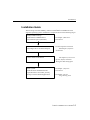
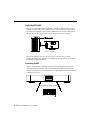
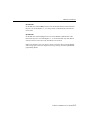
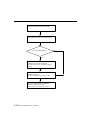
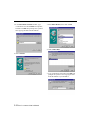
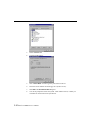
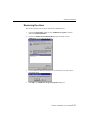
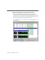
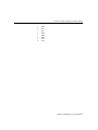
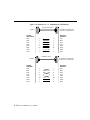
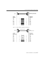
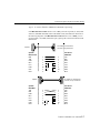
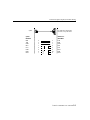
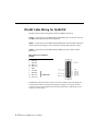
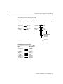
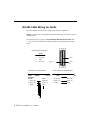
1
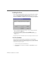
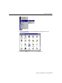
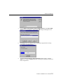
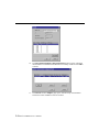
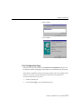
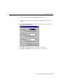
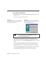
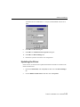
S m a r t i o C168H/PCI User’s Manual 8 Port Serial Board for PCI Bus Third Edition December 2000 This manual is also available on CD-ROM and at the Moxa web site. Moxa Technologies Co., Ltd. Tel: +866-2-8919-1230 Fax: +886-2-8919-1231 www.moxa.com [email protected] S m a r t i o C168H/PCI User’s Manual The product described in this manual is furnished under a license agreement and may be used only in accordance with the terms of that agreement. Copyright Notice Copyright 1999, 2001 Moxa Technologies Co., Ltd. All rights reserved. Reproduction in any form without permission is prohibited. Trademarks MOXA is a registered trademark of Moxa Technologies Co., Ltd. All other trademarks or registered marks in this manual belong to their respective owners. Disclaimer Information in this document is subject to change without notice and does not represent a commitment on the part of Moxa. Moxa provides this document “as is”, without warranty of any kind, either expressed or implied, including, but not limited to, its particular purpose. Moxa reserves the right to make improvements and/or changes to this manual, or to the products and/or programs described herein at any time. Information provided in this manual is intended to be accurate and reliable. However, Moxa Technologies assumes no responsibility for its use, or for any infringements on the rights of fourth parties that may result from its use. This document could include unintentional technical and/or typographical errors. Changes are periodically made to the information herein, and these changes are incorporated into new editions of the manual. MOXA Internet Services Customer satisfaction is one of our number one concerns. To ensure that customers receive the full benefit of our products, Moxa Internet Services has been set up to provide technical support, driver updates, product information, and user’s manual updates. The following services are provided E-mail for technical support: [email protected] FTP site for free driver updates: ......................ftp://ftp.moxa.com or ...............................................ftp://ftp.moxa.com.tw user ID: ................................ftp password: ............................your_email_address World Wide Website for product information: ...............................................www.moxa.com ...............................................www.moxa.com.tw or About This Manual This manual comprises six chapters and one appendix, and is written for the installer, system administrator, and software programmer. If you are a first-time installer and system administrator, we recommend that you read the everything except chapter 4, Serial Programming Tools. If you are a software programmer, refer to chapter 4, Serial Programming Tools. If you need cable wiring information, see chapter 5, Connection Option (Opt8x) and Cable Wiring. If you encounter installation problems, refer to chapter 6, Troubleshooting. Chapter 1 Introduction This chapter gives an overview, features, package check-list, and overall installation guide for C168H/PCI. Chapter 2 Hardware Installation Details the hardware installation procedure for C168H/PCI, and discusses the Opt8x connection option. Chapter 3 Software Installation Describes the software installation procedure, board and port configuration, as well as driver updating and removal for Windows NT/95/98 operating systems. Chapter 4 Serial Programming Tools Gives a rough description of the programming tools for various OS platforms, including PComm Lite under Windows NT/95/98. The Opt8J RS-485 programming issue is also discussed. Chapter 5 Connection Option (Opt8x) and Cable Wiring This chapter describes RS-232/422/485 cable wiring for each connection option (Opt8x). Chapter 6 Troubleshooting Discusses problems that could arise when using C168H/PCI, and solutions to overcome the problems. Appendix Technical Reference This chapter describes specifications, PCI, UART, and DB62 pinouts. Table of Contents 1 Introduction ............................................................................... 1-1 Overview------------------------------------------------------------------------------------------------------------------------ 1-1 Features------------------------------------------------------------------------------------------------------------------------ 1-2 Checklist----------------------------------------------------------------------------------------------------------------------- 1-3 Installation Guide ----------------------------------------------------------------------------------------------------------- 1-5 2 Hardware Installation............................................................... 2-1 Installing the Smartio C168H/PCI Board --------------------------------------------------------------------------- 2-1 Installing Connection Option Opt8x ---------------------------------------------------------------------------------- 2-2 3 Software Installation................................................................ 3-1 Windows NT------------------------------------------------------------------------------------------------------------------ 3-1 Installing the Driver ----------------------------------------------------------------------------------------------------- 3-2 Configuring Board and Port---------------------------------------------------------------------------------------- 3-12 Updating the Driver --------------------------------------------------------------------------------------------------- 3-17 Removing the Driver-------------------------------------------------------------------------------------------------- 3-17 Windows 95/98 ------------------------------------------------------------------------------------------------------------ 3-18 Installing a Driver------------------------------------------------------------------------------------------------------ 3-19 Configuring Board and Port---------------------------------------------------------------------------------------- 3-27 Updating the Driver --------------------------------------------------------------------------------------------------- 3-29 Removing the driver -------------------------------------------------------------------------------------------------- 3-31 4 Serial Programming Tools ....................................................... 4-1 PComm Installation----------------------------------------------------------------------------------------------------------- 4-1 PComm Programming Library -------------------------------------------------------------------------------------------- 4-2 Utility ---------------------------------------------------------------------------------------------------------------------------- 4-2 RS-485 Programming for Opt8J --------------------------------------------------------------------------------------- 4-6 5 Connection Option (Opt8x) & Cable Wiring ........................... 5-1 RS-232 Cable Wiring for Opt8A/B/C/D/S -------------------------------------------------------------------------- 5-1 RS-422 Cable Wiring for Opt8J/F/Z -------------------------------------------------------------------------------- 5-10 RS-485 Cable Wiring for Opt8J -------------------------------------------------------------------------------------- 5-12 RS-422/485 Impedance Matching ---------------------------------------------------------------------------------- 5-13 6 Troubleshooting........................................................................ 6-1 General Troubleshooting ------------------------------------------------------------------------------------------------- 6-1 Windows NT------------------------------------------------------------------------------------------------------------------ 6-2 Windows 95/98 -------------------------------------------------------------------------------------------------------------- 6-3 7 Technical Reference ...................................................................1 Specifications -------------------------------------------------------------------------------------------------------------------1 PCI ----------------------------------------------------------------------------------------------------------------------------------1 UART 16C550C-----------------------------------------------------------------------------------------------------------------2 DB62 Connector Pinouts----------------------------------------------------------------------------------------------------3 1 1 Introduction Overview Smartio— Smart Multiport Async Solutions Smartio products represent smart, multiport, serial I/O solutions for the modern technological world. Smartio C168H/PCI is designed for a 32-bit PCI bus with the plug-and-play feature. It offers 8 serial ports for connecting terminals, modems, printers, data acquisition equipment, and other serial devices to a PC. Smartio C168H/PCI is a well-designed, fine-tuned device driver, and as such makes full use of the 32 byte Tx/Rx FIFO and on-chip H/W flow control, making it possible to transfer data, without loss, at speeds up to 921.6 Kbps. This product offers a reliable and high performance solution for serial multiport communications. Board Applications The Smartio C168H/PCI board can be used for many applications. Here are just a few: • Internet/Intranet Connection • Remote Access Applications • Multi-User Applications • Industrial Automation • Office Automation • Telecommunications • PC-based (vending) Machine or Kiosk System • POS (Point-Of-Sale) System PCI Solution The Smartio C168H/PCI board complies with PCI Spec. 2.1, and since the hardware Smartio C168H/PCI User’s Manual 1-1 configuration for IRQ and memory addresses is done automatically by the PCI BIOS, it does not require either switches or jumpers. This means that the board must be plugged in first before installing the driver software. For more PCI information, refer to the Technical Reference appendix. Operating System Support Smartio C168H/PCI supports Windows NT, Windows 95/98, and DOS, with userfriendly installation, configuration, and performance. MOXA Serial Comm Tool MOXA PComm is an easy-to-use serial communication library that runs under Windows NT and Windows 95/98. The library comes with sample applications developed with compilers such as Visual Basic, Visual C++, and Borland Delphi. It contains the useful diagnostic, monitor, and terminal emulation utilities, making it easy to develop your own applications. Furthermore, you can debug and monitor communication status, terminal emulation, and even file transfers. Features v v v v v v v v v v v v v v v v Compact board size (half-size) Plug and play, no switches or jumpers Surge/isolation protection option High speed 16C550C Communication Controller with on-chip hardware flow control; no data loss, even at high transmission speeds Windows NT/95/98 device drivers and PComm serial comm tool Bus interface: 32-bit PCI Number of ports: 8 I/O address: assigned by PCI BIOS IRQ: assigned by PCI BIOS Data bits: 5, 6, 7, 8 Stop bits: 1, 1.5, 2 Parity: none, even, odd, space, mark UART: 8 Í 16C550C or compatible Speed: 50 – 921.6 Kbps Connectors: 8 Í DB25/DB9, male or female Data signals: RS-232-TxD, RxD, RTS, CTS, DTR, DSR, DCD, GND RS-422-TxD+(B), TxD-(A), RxD+(B), RxD-(A), GND 1-2 Smartio C168H/PCI User’s Manual Introduction v v v v (Opt8J:RTS+(B), RTS-(A), CTS+(B), CTS-(A)) RS-485-Data+(B), Data-(A), GND Operating temp: 0 – 55 ℃ Power requirement: 180 mA max. (+5V) 110 mA max. (+12V) 160 mA max. (-12V) Dimensions: 123 Í 100 cm Popular OS supported: C168H/PCI ü Windows NT ü Windows 95/98 Dos R 3: Driver supported by Moxa and shipped with product R: Driver supported by Moxa and shipped by request Note: You can download the latest driver versions for the above OS from the MOXA FTP service. Drivers for other OS may also be available. Check the Moxa web site for complete information. Checklist Smartio C168H/PCI is shipped with the following items: Smartio C168H/PCI 8 port serial board Software CD containing: l Windows NT and Windows 95/98 device drivers l PComm Lite v This User’s Manual v One of the following connection options: v v Opt8A/Opt8B/Opt8S v v RS-232 connection box with 8 DB25 female/male ports (surge protection for Opt8S). 1.5 meter DB62 to DB62 cable. Smartio C168H/PCI User’s Manual 1-3 Opt8C/Opt8D v RS-232 octopus cable with 8 male DB25 port connectors, for Opt8C or DB9 for Opt8D (1 meter long). Opt8F/Opt8Z v v v RS-422 connection box with 8 female DB25 port connectors (isolation protection for Opt8F). 1.5 meter DB62 to DB62 cable. 110V or 220V adapter included. Opt8J v v v RS-422/485 connection box with 8 female DB25 port connectors. 1.5 meter DB62 to DB62 cable. 110V or 220V adapter included. 1-4 Smartio C168H/PCI User’s Manual Introduction Installation Guide This section gives a brief summary of how to install Smartio C168H/PCI for each supported operating system. Installation is simple and involves the following stages: Check PCI BIOS settings. Install Smartio C168H/PCI board and connection option (cable/box) See chapter 2, Hardware Installation Install software from diskette and configure driver for board and ports See the respective OS section from chapter 3, Software Installation Connect cables to the devices See chapter 5, Connection Option (Opt8x) and Cable Wiring for cable wiring specs Restart system. Check the driver initialization status. If system restart is successful, you may develop or execute desired applications. See chapter 3, Software Installation See chapter 4, Serial Programming Tools Smartio C168H/PCI User’s Manual 1-5 1-6 Smartio C168H/PCI User’s Manual 2 2 Hardware Installation Installing Smartio C168H/PCI consists of both hardware and software installation. This chapter describes how to install the hardware, and in the next chapter, we discuss software installation. The no-switch/no-jumper Smartio C168H/PCI board hardware configuration is straightforward, since the IRQ number and I/O addresses are automatically assigned by the PCI BIOS. This means that the board MUST be plugged in before installing the driver software. Installing the Smartio C168H/PCI Board Step 1: Turn off the PC and disconnect the power cable. Warning! Make sure your system is turned off before installing an expansion board. If you do not first shut down the computer, you risk damaging both the PC and the board. Step 2: Remove the PC cover. Step 3: Remove the slot cover bracket if there is one. Step 4: Plug the Smartio C168H/PCI(s) into the PC’s free PCI expansion slot(s). Step 5: Fasten the holding screw to fix the control board in place. Step 6: Replace the system cover. Step 7: Connect one of the connection boxes/cables (and adapter if required) detailed in the next section. Smartio C168H/PCI User's Manual 2-1 Step 8: Note ! Turn on your PC. The BIOS will automatically assign the IRQ and memory address. Each board must occupy one unique IRQ and one unique memory address, assigned automatically by the PCI BIOS. You may, however, use the PC's PCI-slot BIOS setup to manually assign a free IRQ number. This method, however, is usually not available to assign the memory address. The IRQ numbers that can be used are 2, 3, 4, 5, 9, 10, 11, 12, and 15. The I/O addresses that can be used range from 0x0000 to 0xFFFF. Step 9: Proceed with the software installation, detailed in the next chapter, Software Installation. Installing Connection Option Opt8x Use one of the following connection options to set up your Smartio C168H/PCI. After that, connect your modem, serial printer, PC COM1/2, bar code reader, POS device, instrument, or any other serial device to the board’s DB25/DB9 connectors. Refer to the chapter Connection Option (Opt8x) and Cable Wiring for RS232/422/485 cable wiring specs. 2-2 Smartio C168H/PCI User’s Manual Hardware Installation Opt8A/Opt8B/Opt8S Plug one end of the DB62 cable into Smartio C168H/PCI’s DB62 bracket connector, and then carefully tighten the attachment screws. After that, plug the other end of the cable into the RS-232 connection box's DB62 connector. Note that both ends of the cable are identical. Smartio C168H/PCI Opt8A/Opt8B/Opt8S Opt8C/Opt8D Plug one end of the DB62 cable into Smartio C168H/PCI’s DB62 bracket connector, and then carefully tighten the attachment screws. P1 P5 P2 P3 P4 P6 P7 P8 Smartio C168H/PCI Opt8C/Opt8D Smartio C168H/PCI User’s Manual 2-3 Opt8J/Opt8F/Opt8Z Plug one end of the DB62 cable into Smartio C168H/PCI’s DB62 bracket connector, and then carefully tighten the attachment screws. After that, plug the other end of the cable into the RS-232 connection box's DB62 connector. Note that both ends of the cable are identical. Don't forget to attach the Opt8J/F/Z’s power adapter. Smartio C168H/PCI Opt8F/Opt8Z/Opt8J Refer to the chapter Connection Option (Opt8x) and Cable Wiring for RS232/422/485 cable wiring, and refer to the chapter Serial Programming Tools for RS232/422/485 programming details. Operating Opt8J Opt8J is an RS-422/485 connection box that is used with MOXA’s 8-port boards, including Smartio C168H/PCI. It has 8 female DB25 port connections, and 8 DIP switches on the side, with each switch used to set the communication mode (RS-422 or RS-485) of one port. 12345678 DIP ON RS-422/485 Port Switch of Opt8J 1 DIP 2-4 Smartio C168H/PCI User’s Manual 2 3 4 5 6 7 ON 8 Hardware Installation RS-422 Mode Set the DIP switch to the OFF position to use the RS-422 interface. This means that the port is set to full-duplex; i.e., it is always ready to simultaneously transmit and receive data. RS-485 Mode Set the DIP switch to the ON position to use 2-wire RS-485 communication. This means that the port is set to half-duplex; i.e., it can transmit data only when RTS is asserted, and can receive data only when RTS is not asserted. Refer to the chapter Connection Option (Opt8x) and Cable Wiring for RS-422/485 cable wiring specs, and to the chapter Serial Programming Tools for Opt8J RS-485 programming details. Smartio C168H/PCI User’s Manual 2-5 2-6 Smartio C168H/PCI User’s Manual 3 3 Software Installation In this chapter, we describe driver installation and configuration, and driver update and removal procedures for Windows NT/95/98. You must first complete the hardware installation before proceeding with the software installation. If you wish to develop your own applications, please refer to the next chapter, Serial Programming Tools, for a discussion of serial programming issues. Windows NT Windows NT can support up to 256 serial ports, from COM1 to COM256. To fully utilize Windows NT’s advanced multi-process and multi-thread features, Moxa has developed pure, 32-bit device drivers for Smartio C168H/PCI, and other MOXA multiport boards. These drivers all conform to the Win32 COMM API standard. Go directly to the section Installing the Driver to install the driver for the first time. Refer to the section Configuring Board and Port to learn how to re-configure a board that is already installed. Refer to the section Updating the Driver for information on how to update the driver for a board that is already installed. Refer to the section Removing the Driver to see how to delete a driver from your system. Smartio C168H/PCI User's Manual 3-1 Installing the Driver The key step in installing the Windows NT driver for your Moxa Smartio C168H/PCI board is the Moxa Smartio/Industio Configuration Panel, shown below. You will either click on Add, Remove, or Property, depending on whether you are installing the driver for the first time, removing the driver, or simply updating the configuration. l l l If you are installing a board for the first time, or you are installing an additional board, you will use the Add button. If you would like to remove a board, you will use the Remove button. To update the configuration properties of a particular board, you will use the Property button. The following sections contain details of how to add, configure, and remove a driver. First Time Installation In this section we give the procedure you should follow to install the Smartio C168H/PCI driver for the first time under Windows NT 3.51/4.0. To begin with, make sure that all of the boards have been properly plugged into your system’s PCI slots, as described in the previous chapter. 1. Log onto your NT system as the administrator. 2. From the Windows NT desktop, click on Start à Control Panel to open the Control Panel. 3-2 Smartio C168H/PCI User’s Manual Software Installation 3. Click on the Network icon (shown highlighted in the figure below) in the Control Panel window. 4. Click on the Adapters tab, and then click the Add button. Smartio C168H/PCI User’s Manual 3-3 5. Click on Have Disk... in the Select Network Adapter window. 6. Specify the exact path of the driver disk, G:\Windows.nt for the example shown below (use a different drive letter— A, B, C, etc.— if the disk is located in a different drive), and then click OK to continue. 3-4 Smartio C168H/PCI User’s Manual Software Installation 7. Click on MOXA Smartio/Industio Family multiport board from the Select OEM Option window to highlight it, and then click OK to begin installing the driver. 8. The Setup window will appear briefly to indicate that program files are being copied to the specified directory. 9. The Moxa Smartio/Industio Configuration Panel window appears. Click the Add button to open the Property info box to change port settings and advanced FIFO configurations. Smartio C168H/PCI User’s Manual 3-5 10. Select C168 PCI Series board from the Board Type pull-down list. Click on a specific port in the Port info-box, and then click on Port Setting to open the Port X properties window. . Note: Step 11 is optional if you wish to manually assign COM numbers to ports. 11. Select a COM number for the port from the Port Number pull-down list. 3-6 Smartio C168H/PCI User’s Manual Software Installation 12. Check the Auto Enumerating COM Number checkbox to have subsequent ports mapped to consecutive COM numbers. For example, if COM3 is assigned to Port 1, then COM4 will be automatically assigned to Port 2, etc. . Note: You may skip steps 13 and 14 if the system does not require special performance tuning. 13. Select an Rx FIFO Trigger from the Rx FIFO Trigger pull-down list. Check the Set the change to all ports checkbox if you want to apply this Rx FIFO Trigger to every port. 14. Select a Tx FIFO Size from the Tx FIFO size pull-down list. Check the Set the change to all ports checkbox if you want to apply this Tx FIFO Size to all ports. 15. Click OK in the Port X window to confirm the port settings and return to the Property window. Click OK to complete the port settings. Smartio C168H/PCI User’s Manual 3-7 16. The Moxa Smartio/Industio Configuration Panel window reopens, indicating that the Smartio C168H/PCI board has been successfully installed. Click OK to continue. 17. The Network window Adapters page opens, with the newly installed Moxa board listed. Click on Close to close the window. 3-8 Smartio C168H/PCI User’s Manual Software Installation 18. Windows NT will run through some basic procedures, after which you will be prompted to restart the system. Click on Yes to restart the computer at this time. . Note: The driver configuration will NOT take effect until you restart the PC. Once the system restarts, you can check the event log issued by the MOXA driver to see if the ports on the board were initialized successfully. 1. From the Windows NT desktop click on Start à Programs à Administrative Tools (Common) à Event Viewer to open the Event Smartio C168H/PCI User’s Manual 3-9 Viewer window. 2. Locate and then highlight the Mxserp line, as shown below, and then press Enter. 3-10 Smartio C168H/PCI User’s Manual Software Installation 3. . The Event Detail window opens, indicating that the MOXA C168 PCI series board has been enabled. Click on Close to close the window. Note: If an error message similar to Cannot find any configured MOXA Smartio/Industio series board! pops up, see the Troubleshooting chapter for solutions. You can start developing applications with the PComm library (see Serial Programming Tools) or Microsoft Win32 API, once the board and driver have been installed and the system has restarted successfully. You may also execute readymade applications, such as the PComm utility Terminal Emulator (see Serial Programming Tools) or HyperTerminal, to transmit/receive data, as well as Remote Access Service, to provide dial-up networking capabilities. Smartio C168H/PCI User’s Manual 3-11 Configuring Board and Port Re-Configuring Port Settings If the driver is already installed and you only need to re-configure the ports, either click on Start è Program Files è MOXA Utility è Moxa Smartio/Industio Configuration Panel è Property, or follow steps 1–5 listed below, and then refer to steps 11–18 from the previous subsection. 1. From the Windows NT desktop, click on Start à Control Panel to open the Control Panel. 2. Click on the Network icon (shown highlighted in the figure below). 3. Select MOXA Smartio/Industio Family Adapter from the list on the Adapters page, and then click on Properties… . 3-12 Smartio C168H/PCI User’s Manual Software Installation 4. Click on Property to continue. 5. Once the Property window opens, follow steps 11 to 18 from the previous section to change the configuration settings. Smartio C168H/PCI User’s Manual 3-13 Configuring Another C168H/PCI Board Read this section if you are installing another MOXA C168H/PCI board. As long as the Windows NT system has sufficient resources, up to four C168H/PCI boards can be installed on one system. To proceed, either click on Start à Program Files à MOXA Utility à Moxa Smartio/Industio Configuration Panel à Property, or follow steps 1–5 listed below, and then refer to steps 11–18 from the previous section. 1. From the Windows NT desktop, click on Start à Control Panel to open the Control Panel. 3-14 Smartio C168H/PCI User’s Manual Software Installation 2. Click on the Network icon (shown highlighted in the figure below). 3. Select MOXA Smartio/Industio Family Adapter from the Network Adapters list, and then click on Properties… . 4. The Moxa Smartio/Industio Configuration Panel opens. Click on Property to continue. Smartio C168H/PCI User’s Manual 3-15 5. The board’s Property window opens. 6. Now refer to steps 10 – 18 in First Time Installing Driver from the Windows NT section. Removing an Existing C168H/PCI Board Configuration One option is to simply unplug the C168H/PCI board, while the computer is shut down. After restarting the computer, you will find that the configuration has been automatically removed. Alternatively, you could perform the removal from the Moxa Smartio/Industio Configuration Panel dialog box, by highlighting the board to be 3-16 Smartio C168H/PCI User’s Manual Software Installation removed, and then clicking on the Remove button. Updating the Driver To update the Smartio C168H/PCI driver you must first remove the exiting driver, and then install the new driver. 1. Open Control Panel, click on the Network icon, and then select the Adapters tab. 2. Choose MOXA Smartio/Industio Family Adapter from the Network Adapters list. 3. Click on Remove in the Network dialog box. 4. Click on Close in the Network dialog box. 5. Restart the system. 6. To install a new driver, refer to steps 1 to 21 in the subsection First Time Installing Driver, from the Windows NT section. Removing the Driver To remove the Smartio C168H/PCI board driver, you should: 1. Open Control Panel, click on the Network icon, and then select the Adapters tab. 2. Choose MOXA Smartio/Industio Family Adapter from the Network Adapters list. 3. Click on Remove in the Network dialog box. Smartio C168H/PCI User’s Manual 3-17 4. Click on Close to exit the Network dialog box. 5. Restart the system to activate the new configuration. Windows 95/98 The Windows 95/98 driver supports up to 128 serial ports, from COM1 to COM128. To fully utilize Windows’ advanced multi-process and multi-thread features, Moxa has developed pure, 32-bit virtual device port drivers (VxD), compliant with communication drivers (VCOMM), for the Smartio C168H/PCI and other MOXA multiport boards. All of these drivers conform to the Win32 COMM API standard. Go directly to the section Installing a Driver for first time driver installation, or to add more boards. To re-configure the ports for boards that are already installed, refer to the section Configuring Board and Port. To update a driver, see the section Updating the Driver. To remove a driver, go to the section Removing the Driver. 3-18 Smartio C168H/PCI User’s Manual Software Installation Installing the Driver The Plug and Play feature supported by Windows 95/98 allows you to plug the Smartio C168H/PCI board into your PC, and then get to work almost immediately with very little installation effort. Windows 95/98 automatically detects the presence of the new board, and prompts you to install the driver software. You will need the driver diskette to do this. A maximum of 4 Smartio C168H/PCI boards can be installed on one system, provided the system’s I/O addresses and IRQ number resources are sufficient and available. The following flow chart illustrates the driver installation stages for the Smartio C168H/PCI boards. Each stage of the procedure will be discussed in more detail later. Smartio C168H/PCI User’s Manual 3-19 Install the Smartio PCI board in the PC. Start Windows 95/98 to detect the board. Driver installed before? No Install the driver from the diskette. See First Time Driver Installation Stage section. Configure the ports. See Port Configuration Stage section. The ports of the Smartio C168H/PCI board are ready to work. See Board and Port Ready Stage section. 3-20 Smartio C168H/PCI User’s Manual Yes Software Installation First Time Driver Installation Stage This stage is relevant if you are adding the first Smartio C168H/PCI board to your PC, and are installing the driver for the first time. The installation of the Smartio C168H/PCI board for Windows 95 and Windows 98 is slightly different, and will be described in two separate columns. The left column is for Windows 95 and the right column for Windows 98. If a MOXA C168H/PCI board has previously been installed and you are adding another board, the system will prompt you to skip to the Port Configuration Stage discussed in the next section. 1. Upon detecting the first new Smartio C168H/PCI board, Windows 95/98 will automatically display a New hardware found message box, after which the following dialog boxes will pop up. Click on Next to continue. Windows 95 Windows 98 2. Click on Other Locations. 2. Select Display a list..., then click on Next. Smartio C168H/PCI User’s Manual 3-21 3. In the Select Other Location window, type A:\Windows.95 in the Location text input box, and then click OK. This prompts the system to start copying the files from the diskette. 3. Select Other Devices, then click on Next. 4. Click on Have Disk. 4. Click on Finish. 5. Type A:\Windows.95 and then click OK. This prompts the system to start copying the files from the diskette to your harddrive. 3-22 Smartio C168H/PCI User’s Manual Software Installation 6. Click on Next. 7. Click on Next. Port Configuration Stage After the driver has been installed, the C168 PCI Series Installation dialog box will be displayed, and the port mapping will be taken care of automatically by the system. If one MOXA C168H/PCI board was previously installed, and you are adding another board to your system, you will be prompted to follow the port configuration instructions discussed in this section. 1. Click on a specific port. 2. Click on Port Setting to open the Port X dialog box. Smartio C168H/PCI User’s Manual 3-23 3. Select a COM number for the port from the Port Number pull-down list. Note! 4. Click on the Auto Enumerating COM Number checkbox to have subsequent ports mapped to consecutive COM numbers. For example, if COM 3 is assigned to Port 1, then COM 4 will be automatically assigned to Port 2. Note! 5. Skip step 4 if you wish to manually assign COM numbers to your ports. Skip steps 5 to 8 if your system does not require special performance tuning. Select an Rx FIFO Trigger from the Rx FIFO Trigger pull-down list. Rx FIFO trigger levels are available at 1, 4, 8, and 14 bytes, with the default value set at 14 bytes. 6. Check Set the change to all ports checkbox if you would like to apply this Rx FIFO Trigger to all of your ports. 3-24 Smartio C168H/PCI User’s Manual Software Installation 7. Select a Tx FIFO Size from the Tx FIFO Size pull-down list. Tx FIFO sizes are available from 1 to 16 bytes, with the default value set at 16 bytes. 8. Check Set the change to all ports checkbox if you would like to apply this Tx FIFO Size to all of your ports. 9. Click OK in the Port X dialog box to confirm the port settings. 10. Click OK in the Property dialog box to complete the port settings. Smartio C168H/PCI User’s Manual 3-25 Board and Port Ready Stage There is a slight difference between the Board and Port Ready Stage for Windows 95 and Windows 98. In this stage, we complete the driver installation. Windows 95 After configuring the ports, you can immediately use the Smartio C168H/PCI board COM ports without restarting Windows 95. Windows 98 After configuring the ports, click on Finish. The Smartio C168H/PCI board COM ports can be used without restarting Windows 98. C168 PCI Series Note! If an error message similar to “C168 PCI (BusNo=x, DevNo=x, Port1=COMx) interrupt number is invalid!” pops up, refer to the Troubleshooting chapter for help. If you want to add more boards after installing the driver, simply plug in the additional Smartio C168H/PCI boards and they will be automatically detected by Windows 95/98. In this case, skip to Port Configuration stage to take care of the port settings. At this point, the Smartio C168H/PCI board driver installation should be complete, including configuration of the board and ports. Please refer to the next section, Configuring Board and Port, if you need to make any changes to the configuration. You may start developing applications with PComm library (See Serial Programming Tools) or Microsoft Win32 API, as soon as the board and driver have been successfully installed and restarted. You can also execute any ready-made 3-26 Smartio C168H/PCI User’s Manual Software Installation applications, such as the PCo mm utility Terminal Emulator (See Serial Programming Tools) or HyperTerminal to transmit/receive data, as well as Remote Access Service to provide dial-up networking capabilities. Configuring Board and Port Follow the procedure listed below to re-configure port COM numbers for installed boards and drivers running under Windows 95/98. Instead of following the procedures listed below, you may also click on Start à Program Files à MOXA Utility à Moxa Smartio/Industio Configuration Panel à Property à Port Setting. Since this is a PCI board, the system will automatically add or remove the board’s configuration once the board has been added or unplugged. This saves you the effort of adding or removing the configuration manually. 1. Open the Control Panel, click on the System icon, select the Device Manager tab, and then choose Moxa Smartio/Industio multiport board. 2. Click on the desired C168H/PCI board entry, and then click on Properties. 3. Select the Ports Configuration tab. 4. Click on a port, and then click on Port Setting to re-assign the COM number for Smartio C168H/PCI User’s Manual 3-27 the Smartio C168H/PCI port mapping. Note! 5. Check the Auto Enumerating COM Name checkbox to assign consecutive COM numbers for subsequent ports. For example, if COM 3 is assigned to Port 1, then COM 4 will be automatically assigned to Port 2. Note! 6. Skip Step 5 if you would like to manually assign COM numbers to the ports. Skip Steps 6 and 7 if the system does not require special performance tuning. Re-assign the Rx FIFO Trigger by selecting a number from the pull-down list. Check the Set the change to all ports checkbox if you would like to apply this setting to all ports. The available Rx FIFO trigger levels are 1, 4, 8, and 14 bytes, with the default value set at 14 bytes. 7. Re-assign the Tx FIFO Size by selecting a number from the pull-down list. Make sure the Set the change to all ports checkbox is checked if you would like to apply this setting to all ports. 3-28 Smartio C168H/PCI User’s Manual Software Installation Tx FIFO sizes are available from 1 to 16 bytes, with the default value set at 16 bytes. 8. Click OK in the Port X dialog box. 9. Click OK in the C168 PCI Series Properties dialog box. 10. Click OK in the Device Manager tab. 11. Restart the system to activate the new configuration. Updating the Driver In this section, we discuss how to update the Windows 95/98 driver to enhance the function of the board. 1. Open the Control Panel, click on System, and then select the Device Manager tab. 2. Click on MOXA C168 PCI Series and then click on Properties. Smartio C168H/PCI User’s Manual 3-29 3. Select the Driver tab. 4. Click on Update Driver... . 5. Click on Have Disk... and then type the path of the new driver. 6. Insert the source diskette into the floppy drive (if there is one). 7. Click OK in the Install from Disk dialog box. 8. You will be prompted to restart the system. Click on Yes to restart, or No if you would like to wait and reboot the system later. 3-30 Smartio C168H/PCI User’s Manual Software Installation Removing the driver This section explains how to remove the Smartio C168H/PCI driver. 1. Open the Control Panel, double click on Add/Remove Programs , and then select the Install/Uninstall tab. 2. Click on the MOXA Smartio/Industio Driver option and then click on Add/Remove to start removing the driver. 3. Click on Yes in the following message box to confirm that you really want to remove the driver. 4. Click OK in the Add/Remove Programs Properties dialog box. Smartio C168H/PCI User’s Manual 3-31 4 4 Serial Programming Tools Moxa supports several easy, but powerful, serial programming libraries and communication troubleshooting utilities that run under Windows NT and Windows 95/98. Using MOXA Serial Programming Tools can save you a substantial amount of developing time. The following sections give details about the installation, the library, and the utilities, for various OS platforms. PComm, the professional PC serial comm tool, is a software package for Windows NT and Windows 95/98 that consists of: l A powerful serial communication library for easy programming in the most popular programming languages. The serial communication library is useful for developing data communication applications for remote access, data acquisition, and industrial control in a Windows NT or Windows 95/98 environment. It is also an easier solution compared to the more complex Windows Win32 COMM API. l Useful utilities such as Diagnostic, Monitor, and Terminal Emulator. l Illustrative sample programs. l Comprehensive on-line documentation. P C o m m Installation To install PComm, run \Setup.exe from the diskette included with the board. Note that the PComm diagnostic and monitor utilities are for MOXA boards only; therefore, these two utilities will not work on other brands of serial board. Once PComm has been successfully installed, click on Start, and select Program Files and the PComm Lite group to bring up a list of utilities and documents. Smartio C168H/PCI User's Manual 4-1 P C o m m Programming Library The serial communication library assists you in developing serial communication programs for any COM port that complies with Microsoft Win32 API. It facilitates the implementation of multi-process and multi-thread serial communication programs, thus reducing program-developing time by a remarkable amount. This serial communication library provides a complete library of functions and sample programs for Visual C++, Visual Basic, and Delphi. To view detailed function descriptions and sample programs, click on Start à Program Files à P C o m m Lite à P C o m m Lib Help, and then P C o m m Porting Notes or P C o m m Programming Guide. Alternatively, you may also refer to the sample programs located in the PComm directory. Utility Given below are brief descriptions of each utility. For more information, please see the on-line help located on the diskette. 4-2 Smartio C168H/PCI User’s Manual Serial Programming Tools Diagnostic (for MOXA boards only) This convenient diagnostic program, which ONLY works for MOXA boards and ports, provides internal and external testing capabilities, including IRQ, TxD/RxD, UART, CTS/RTS, DTR/DSR, and DTR/DCD testing. It can be used to verify that both the software and hardware are functioning correctly. To run the Diagnostic program, click on Start, and then select Program Files, P C o m m Lite, and Diagnostic. Smartio C168H/PCI User’s Manual 4-3 Monitor (for MOXA boards under Windows NT Only) This useful port status monitoring program allows you to keep an eye on selected MOXA COM ports. It monitors data transmitting/receiving throughput and communication line status, both of which are updated and displayed on the screen at periodic time intervals. By clicking on the specific port being displayed, you can see the current communication parameters and status of that port. To run the Monitor program, click on Start, and then select Program Files, P C o m m Lite, and Monitor. 4-4 Smartio C168H/PCI User’s Manual Serial Programming Tools Terminal Emulator Terminal Emulator is used to simulate various port connections, allowing you to see if signal transmission is functioning correctly. It features multiple-windows, and supports both VT100 and ANSI terminal types, allowing you to transfer data interactively, send patterns periodically, and transfer files using ASCII, XMODEM, YMODEM, ZMODEM, and KERMIT protocols. To run Terminal Emulator, click on Start, and then select Program Files, P C o m m L i t e , and Terminal Emulator. Smartio C168H/PCI User’s Manual 4-5 RS-485 Programming for Opt8J If you intend to use Opt8J for RS-485 communications, follow the RS-485 programming guide given below, and refer to the chapter Connection Option (Opt8x) and Cable Wiring for more Opt8J RS-485 operation details. The Opt8J option only supports 2-wire half-duplex RS-485 communications. Data +/− pins are used for both data transmitting and receiving, depending on the RTS signal. The port switch for each port should be set to the On position. The port is used for transmitting data if RTS is asserted and is used for receiving data if RTS is not asserted. This RTS scheme is suitable for any system that permits RTS control from within application programs. This includes Windows NT, Windows 95/98, DOS, and UNIX. How to transmit and receive data under Windows NT and Windows 95/98 We recommend that you configure Smartio C168H/PCI ports as follows to acquire precise timing control when using RS-485 2-wire transmission. There are 2 ways to control RS-485 2-wire transmission. Solution 1 The following model is commonly used for RS-485 2-wire transmission. 4-6 Smartio C168H/PCI User’s Manual Serial Programming Tools sio_SetWriteTimeouts(port, 0); /* Set sio_write() into block mode */ sio_RTS(port, 1); /* Turn on RTS signal. The RS -485 port is ready for transmitting data. */ sio_write(port, buff, 10); /* Write 10 byte characters in "buff". The function blocks until last character transmitted */ sio_RTS(port, 0); /* Turn off RTS signal. The RS -485 port is ready for receiving data. */ sio_read(port, buff, 10); /* Read 10 bytes */ Solution 2 The PComm library contains a dedicated RS-485 function that integrates the functions given in solution 1 regarding sending data. sio_putb_x(port, buff, tick ); /* . 1. Turn on RTS ; ready for transmitting data 2. Send data. 3. Wait for tick time. 4. Turn off RTS ; ready for receiving data. */ For more information about these functions, refer to the PComm library on-line Help file for Windows NT and Windows 95/98. Smartio C168H/PCI User’s Manual 4-7 4-8 Smartio C168H/PCI User’s Manual 5 5 Connection Option (Opt8x) & Cable Wiring In serial data communications, the term DTE stands for Data Terminal Equipment, such as a terminal or PC COM1/2, and the term DCE stands for Data Communication Equipment, such as a modem. The precise pinouts and cable wiring schemes are as follows. RS-232 Cable Wiring for Opt8A/B/C/D/S The RS-232 8-port connection boxes and octopus cables designed for Smartio C168H/PCI are: Opt8A: 8-port RS-232 DB25 female connection box Opt8B: 8-port RS-232 DB25 male connection box Opt8C: Octopus cable with 8 male RS-232 DB25 ports Opt8D: Octopus cable with 8 male RS-232 DB9 ports Opt8S: 8-port RS-232 DB25 surge protected female connection box Smartio C168H/PCI User's Manual 5-1 Shown below are the pin assignments for various connection options: Opt8A/S (DCE, DB25 Female) 2 3 4 5 6 7 8 20 RxD TxD CTS RTS DTR GND DCD DSR Opt8B/C (DTE, DB25 Male) 2 3 4 5 6 7 8 20 TxD RxD RTS CTS DSR GND DCD DTR Opt8D (DTE, DB9 Male) 5-2 Smartio C168H/PCI User’s Manual Connection Option (Opt8x) and Cable Wiring 1 2 3 4 5 6 7 8 DCD RxD TxD DTR GND DSR RTS CTS Smartio C168H/PCI User’s Manual 5-3 Type 1: To connect S m a r t i o C168H/PCI to a DTE device. Straight-through Cable PC COM2 port, Serial Printer, Terminal, or any DTE Device Opt8A/S Opt8A/S DB25 Female RxD TxD CTS RTS DTR DSR GND DCD DTE Device DB25 Male 2 3 4 5 6 20 7 8 2 3 4 5 6 20 7 8 TxD RxD RTS CTS DSR DTR GND DCD Null Modem Cable PC COM2 port, Serial Printer, Terminal, or any DTE Device Opt8B/C Opt8B/C DB25 Male TxD RxD RTS CTS DSR DTR GND DCD 5-4 Smartio C168H/PCI User’s Manual DTE Device DB25 Male 2 3 4 5 6 20 7 8 2 3 4 5 6 20 7 8 TxD RxD RTS CTS DSR DTR GND DCD Connection Option (Opt8x) and Cable Wiring PC COM2 port, Serial Printer, Terminal, or any DTE Device Opt8D Opt8D DB9 Male RxD TxD CTS RTS DTR DSR GND DCD DTE Device DB25 Male 2 3 8 7 4 6 5 1 2 3 4 5 6 20 7 8 TxD RxD RTS CTS DSR DTR GND DCD Type 2: To connect Smartio C168H/PCI to a DCE device. Null Modem Cable Modem, or any DCE Device Opt8A/S Opt8A/S DB25 Female RxD TxD CTS RTS DTR DSR GND DCD DCE Device DB25 Female 2 3 4 5 6 20 7 8 2 3 4 5 6 20 7 8 RxD TxD CTS RTS DTR DSR GND DCD Smartio C168H/PCI User’s Manual 5-5 Straight-through Cable Modem, or any DCE Device Opt8B/C Opt8B/C DB25 Male TxD RxD RTS CTS DSR DTR GND DCD DCE Device DB25 Female 2 3 4 5 6 20 7 8 2 3 4 5 6 20 7 8 Modem or any DCE Device Opt8D Opt8D DB9 Male RxD TxD CTS RTS DTR DSR GND DCD 5-6 Smartio C168H/PCI User’s Manual RxD TxD CTS RTS DTR DSR GND DCD DCE Device DB25 Female 2 3 8 7 4 6 5 1 2 3 4 5 6 20 7 8 RxD TxD CTS RTS DTR DSR GND DCD Connection Option (Opt8x) and Cable Wiring Type 3: To connect Smartio C168H/PCI to a DTE with 3-pin wiring. If the Hardware flow control feature is set to ON, you must loop back (or short) RTS with CTS, and DSR with DTR, DCD on the MOXA side, indicated with dash-lines in the following diagrams. If the Hardware flow control feature is set to OFF, you can just leave RTS, CTS, DSR, DTR, DCD open, ignoring the connections indicated with dashed lines. PC COM2 port, Serial Printer, Terminal, or any DTE Device Opt8A/S Opt8A/S DB25 Female RxD TxD GND RTS CTS DTR DST DCD DTE Device DB25 Male 2 3 7 5 4 20 6 8 2 3 7 4 5 6 20 8 PC COM2 port, Serial Printer, Terminal, or any DTE Device Opt8B/C Opt8B/C DB25 Male TxD RxD GND RTS CTS DSR DTR DCD TxD RxD GND RTS CTS DTR DSR DCD DTE Device DB25 Male 2 3 7 4 5 6 20 8 2 3 7 4 5 6 20 8 TxD RxD GND RTS CTS DTR DSR DCD Smartio C168H/PCI User’s Manual 5-7 5-8 Smartio C168H/PCI User’s Manual Connection Option (Opt8x) and Cable Wiring PC COM2 port, Serial Printer, Terminal, or any DTE Device Opt8D Opt8D DB9 Male RxD TxD GND RTS CTS DTR DSR DCD DTE Device DB25 Male 2 3 5 7 8 4 6 1 2 3 7 4 5 6 20 8 TxD RxD GND RTS CTS DTR DSR DCD Smartio C168H/PCI User’s Manual 5-9 RS-422 Cable Wiring for Opt8J/F/Z RS-422 connection boxes designed for Smartio C168H/PCI boards are: Opt8J: Connection box with 8 female RS-422/485 DB25 ports. Set the port switch to the OFF position (RS-422) for the desired port(s). Opt8F: Connection box with 8 female RS-422 DB25 ports and a maximum of 500V DC isolation protection, helping to prevent damage caused by high potential voltage. Opt8Z: Connection box with 8 female RS-422 DB25 ports, but without isolation protection. RS-422 Pinouts for Opt8J/F/Z: pt8J/F/Z 2 3 14 16 7 4 5 13 19 RxD+(B) TxD+(B) RxD–(A) TxD–(A) GND CTS+(B) RTS+(B) RTS–(A) CTS–(A) Opt8J only The RS-422 transmission distance can be as much as 4000 ft, and consequently the connection box needs an external power adapter to supply 5V DC power. Either a 110V or 220V AC power adapter can be used with this product, depending on your company’s power supply. 5-10 Smartio C168H/PCI User’s Manual Connection Option (Opt8x) and Cable Wiring Given below are the RS-422 operation modes: RS-422 Point-to-point Opt8F/Z 3 TxD+(B) 16 TxD–(A) 2 RxD+(B) 14 RxD–(A) 7 GND RS-422 Broadcasting RS-422 Device RxD+(B) RxD–(A) TxD+(B) TxD–(A) GND Opt8F/Z 3 TxD+(B) 2 RxD+(B) 16 TxD–(A) 14 RxD–(A) 7 GND RS-422 Device I RxD+(B) TxD+(B) RxD–(A) TxD–(A) GND RS-422 Device N RxD+(B) TxD+(B) RxD–(A) TxD–(A) GND Opt8J RS-422 with Handshaking Opt8J RS-422 Device 3 TxD+(B) 16 TxD–(A) 2 RxD+(B) 14 RxD–(A) 7 GND 5 RTS+(B) 13 RTS–(A) 4 CTS+(B) 19 CTS–(A) RxD+(B) RxD–(A) TxD+(B) TxD–(A) GND CTS+(B) CTS–(A) RTS+(B) RTS–(A) Smartio C168H/PCI User’s Manual 5-11 RS-485 Cable Wiring for Opt8J One of the RS-485 connection boxes designed for Smartio C168H/PCI is: Opt8J: Connection box with 8 female RS-422/485 DB25 ports. Set the port switch to the ON position. The Opt8J option only supports 2-wire half-duplex RS-485 communication. Data +/− pins are used for both data transmitting and receiving, depending on the RTS signal. RS-485 Pinouts for Opt8J: Opt8J 3 7 16 Data+(B) GND Data-(A) 7 GND Data- (A) 16 Multidrop RS-485 Half-duplex Opt8J RS-485 485 Device Master Slave 3 Data+(B) 16 Data–(A) 7 GND Data+(B) Data–(A) GND 5-12 Smartio C168H/PCI User’s Manual Device 1 3 Data+ (B) Point-to-Point RS-485 Half-duplex Opt8J 3 Data+(B) 16 Data–(A) 7 GND RS- Data+(B) Data–(A) GND Connection Option (Opt8x) and Cable Wiring RS-485 Device N Slave Data+(B) Data–(A) GND See the section RS-485 Programming in the chapter Serial Programming Tools for more details on Opt8J RS-485 programming. RS-422/485 Impedance Matching When using RS-422/485 serial communications, an electrical signal travels through two different resistance junctions in a transmission line. The impedance mismatch that exists will sometimes cause signal reflection, distorting the signal. This in turn contributes to communication errors. The solution to this problem is to establish the same impedance at the line ends as in the line itself, by terminating them with resistors. The resistance of the termination resistor should equal the characteristic impedance of the transmission line. Resistors should be added near the receiving side. Opt8J/F/Z RS-422/485 Device 3 16 2 14 5 13 4 19 RxD+(B) RxD–(A) TxD+(B) TxD–(A) CTS+(B) CTS–(A) RTS+(B) RTS–(A) TxD+(B) TxD–(A) RxD+(B) RxD–(A) RTS+(B) RTS–(A) CTS+(B) CTS–(A) Opt8J only Note: 1. represents a termination resistor near the receiving side Smartio C168H/PCI User’s Manual 5-13 2. The suggested termination resistor for AWG #26 cable is 100 ohm. 3. The suggested termination resistor for phone cable is 600 ohm. 5-14 Smartio C168H/PCI User’s Manual Connection Option (Opt8x) and Cable Wiring Smartio C168H/PCI User’s Manual 5-15 6 6 Troubleshooting In this chapter, we list several problems that could arise when using Smartio C168H/PCI, and solutions you can follow to fix the problems. If you are unable to find a solution to your particular problem in this chapter, contact either a dealer or Moxa for help. To receive a quicker response from your dealer, please use the Problem Report Form at the end of this manual. General Troubleshooting 1. While installing the driver, the MOXA driver is unable to detect the MOXA PCI board. Hardware causes and solutions: A. The board is not installed. Please install it. 2. B. The board is not properly plugged into the system. If this is the case, replug the board into a 32-bit PCI slot. It may also be the case that the slot you’ve chosen could be damaged. In this case, try other slots until you find one that works. C. The motherboard does not have an available IRQ for the C168H/PCI board. In this case, enter the BIOS and make sure an IRQ is available in the PCI/PnP settings. The MOXA board and driver are activated but cannot transfer data (either transmitting or receiving). Hardware Causes and Solutions: A. Check to see if the cable is wired correctly. Refer to the Connection Option (Opt8x) and Cable Wiring chapter for correct cabling information. Smartio C168H/PCI User's Manual 6-1 B. Either the cable or board could be defective. Try other ports, cables, and boards to verify this, or use PComm Diagnostic utility to test the MOXA board and port conditions. If Diagnostic reports an error, replace the faulty components. Software Causes and Solutions: C. The Smartio C168H/PCI board will check the line status (CTS) before transmitting data if the RTS/CTS flow control feature is set to Enable in either the configuration or application program. Refer to the Connection Option (Opt8x) and Cable Wiring chapter for proper wiring specs, and check the line status of the suspected port using the diagnostic LED indicators on the mini tester. D. The board controlling application might not be written correctly for the corresponding API of the operating system. To see if this is the case, run another application that you know is good, or use utilities provided by Moxa. You can either use PComm Terminal emulator or HyperTerminal under Windows NT and Windows 95/98. Windows NT This section is specifically for troubleshooting under Windows NT. For general problems and solutions, see the previous section, General Troubleshooting. 1. After the system reboots, the error message “Another drive r in the system, which did not report its resources, has already claimed the interrupt used by xxx.” appears in the Event Log. This indicates that the MOXA board was found, but the IRQ that was assigned conflicts with another adapter’s IRQ setting. Check the PCI BIOS IRQ settings first, and then select an available IRQ. 2. After the system reboots, the error message “Cannot find any configured MOXA Smartio/Industio series board!” appears in the Event Log. Make sure the PCI board is seated firmly in the expansion slot. 3. The COM number of the S m a r t i o C168H/PCI (Bus No=x Dev No=x, Port1=COMx), with device number xx, conflicts with others. 6-2 Smartio C168H/PCI User’s Manual Troubleshooting Different boards have conflicting COM numbers. Change the MOXA board’s COM number mappings. 4. Windows NT system panic (blue screen). One possible reason is an IRQ or I/O address conflict with other ISA Bus adapters, such as LAN and SCSI boards, or the system BIOS. Refer to the corresponding problem in the previous General Troubleshooting section for solutions. Windows 95/98 This section is specific for troubleshooting under Windows 95/98. For general problems and solutions, see the previous section, General Troubleshooting. 1. The system cannot find the S m a r t i o C168H/PCI board! - The boards are not properly plugged in. - The slot being used is defective. Try other slots until you find one that works. - The board might be defective. 2. After the system reboots, the error message “C168H/PCI (BusNo=x, DevNo=x, Port1=COMx) interrupt number is invalid!” appears. This indicates that the MOXA board has been found, but the IRQ that was assigned conflicts with another adapter. Make sure the MOXA board’s IRQ does not conflict with another adapter’s IRQ setting. Check the PCI BIOS IRQ settings and select an available IRQ for the MOXA board. Smartio C168H/PCI User’s Manual 6-3 6-4 Smartio C168H/PCI User’s Manual A 7 Technical Reference Specifications v v v v v v v v v v 32-bit PCI (PCI Spec. 2.1 compliance) 8 4 Assigned by PCI BIOS Assigned by PCI BIOS 50 – 921.6 Kbps 5, 6, 7, 8 1, 1.5, 2 none, even, odd, space, mark 8 Í 16C550C or compatible v Bus interface: Number of ports: Max. No. of boards: IRQ: I/O address: Speed (bps): Data bits: Stop bits: Parity: UART: Data signals: v v v v v Connectors: Operating temp: Power requirement: Dimensions: Operating Systems: 8 Í DB25/DB9 male/female (DTE/DCE) 0 – 55 ℃ 180 mA (+5V), 110 mA (+12V), 160 mA (-12V) 123 Í 100 mm Window NT/95/98 and DOS RS-232-TxD, RxD, RTS, CTS, DTR, DSR, DCD, GND RS-422-TxD+/-, RxD+/-, GND (Opt8J: RTS+/-, CTS+/-) RS-485-Data+/-, GND PCI The 32-bit Smartio C168H/PCI board complies with PCI specifications 2.1. Hardware configurations for IRQ and I/O addresses are automatically assigned by the PCI BIOS. Hence, you must first plug the board in before installing the driver software. Unlike ISA slots, different PCI slots in the same PC may have different bus numbers and device numbers with respect to the PCI specifications. The same PCI board will have different system configurations if switched to a different PCI slot. This is Smartio C168H/PCI User's Manual A-1 referred to as slot-sensitive or slot-dependent, and may apply to PCI slots in PCs with different motherboards and different device number sets. For example, some use 17, 18, 19, and 20 for identifying the respective PCI slots, but some use 11, 12, 13, and 14. Due to slot-dependency, it is necessary to re-configure the driver software once the board is plugged into a different PCI slot. Up to 4 Smartio C168H/PCI boards can be installed in one system. When installing more than one board, remember the order of boards to distinguish the installed boards from each other. UART 16C550C The UART 16C550C chip is an intelligent asynchronous controller supporting one full duplex channel that simultaneously transfers data at 921.6 Kbps speed. To increase the overall data throughput, special features such as on-chip FIFO and onchip hardware flow control are used to reduce the number of interrupts to the onboard CPU and to prevent loss of valuable data. A-2 Smartio C168H/PCI User’s Manual Technical Reference DB62 Connector Pinouts Below we list the pin assignments for the DB62 connector on the bracket. Pin No. Signal 1 2 TxD1 DTR1 3 4 5 6 7 RxD2 DSR2 DCD2 TxD3 DTR3 8 9 10 11 12 13 14 15 RxD4 DSR4 DCD4 RxD5 DSR5 DCD5 TxD6 DTR6 16 17 18 19 20 21 RxD7 DSR7 DCD7 RxD8 DSR8 DCD8 Pin No. Signal Pin No. 22 23 24 25 26 RxD1 DSR1 DCD1 TxD2 DTR2 27 28 29 30 31 32 33 34 RxD3 DSR3 DCD3 TxD4 DTR4 GND TxD5 DTR5 35 36 37 38 39 40 41 42 RxD6 DSR6 DCD6 TxD7 DTR7 GND TxD8 DTR8 Signal 43 44 CTS1 RTS1 45 46 47 GND CTS2 RTS2 48 49 CTS3 RTS3 50 51 52 GND CTS4 RTS4 53 54 55 56 CTS5 RTS5 GND CTS6 57 RTS6 58 59 60 GND CTS7 RTS7 61 62 CTS8 RTS8 Smartio C168H/PCI User’s Manual A-3 A-4 Smartio C168H/PCI User’s Manual Problem Report Form Smartio C168H/PCI Customer name: Company: Tel: E-mail: Fax: Date: 1. Moxa Product: o C168H/PCI Serial Number:___________ 2. Moxa Driver version: ________________ 3. Moxa hardware settings: PCI Slot number ________________________ 4. Operating System: o DOS o Windows 95/98 o Windows NT 3.51 o Windows NT 4.0 o Others 5. PC Host: Make _________ Model _________ 6. CPU: Speed _____MHz Make ______ Model ______ 7. BIOS: Make __________________ Version _______ 8. PCI IRQ Configuration in BIOS: Slot no. IRQ no 1 2 3 4 9. Problem Description: Please describe the symptom as clearly as possible, including any error messages. We may need to follow your description in order to reproduce the symptom. o Board not found. o Board found, but cannot transfer data. o Can transfer data, but data lost o Can transfer data, but data is garbled. o Others: Please give a detailed error message description: Return Procedure For product repair, exchange, or refund, the customer must: v Provide evidence of original purchase v Obtain a Product Return Agreement (PRA) from the sales representative or dealer v Fill out the Problem Report Form (PRF), including as much detail as possible for a shorter product repair time. v Carefully pack the product in an anti-static package, and send it, pre-paid, to the dealer. The PRA should show on the outside of the package, and include a description of the problem, along with the return address and telephone number of a technical contact.