1
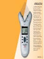
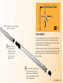
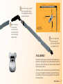
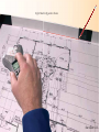
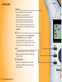
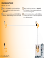
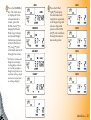
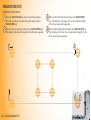
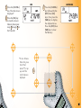
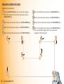
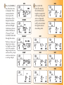
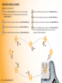
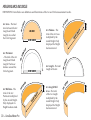
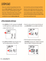
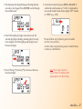
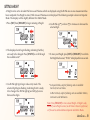
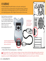
USER’S
GUIDE
Area Take-Off Tool and Digitizing System
Model
#6260
TABLE OF CONTENTS
INTRODUCTION . . . . . . . . . . . . . . . . . . . . . . . . . . . . . . . . . . . . . . 1
SETUP . . . . . . . . . . . . . . . . . . . . . . . . . . . . . . . . . . . . . . . . . . . . . . . . 2
CUSTOM SCALES . . . . . . . . . . . . . . . . . . . . . . . . . . . . . . . . . . . . 36
SETTING A MEASURED CUSTOM SCALE . . . . . . . . . . . . . . . . . . . 36
SETTING AN ENTERED CUSTOM SCALE (IMPERIAL MODE) . . . . . 38
SETTING A HEIGHT . . . . . . . . . . . . . . . . . . . . . . . . . . . . . . . . . . . 39
UNITS OF MEASUREMENT . . . . . . . . . . . . . . . . . . . . . . . . . . . . . 40
PACKAGE CONTENTS . . . . . . . . . . . . . . . . . . . . . . . . . . . . . . . . . . . 2
RIGHT-HAND ASSEMBLY . . . . . . . . . . . . . . . . . . . . . . . . . . . . . . . 4
LEFT-HAND ASSEMBLY . . . . . . . . . . . . . . . . . . . . . . . . . . . . . . . . . 6
GETTING STARTED. . . . . . . . . . . . . . . . . . . . . . . . . . . . . . . . . . . . . 8
DIGITIZER MODE . . . . . . . . . . . . . . . . . . . . . . . . . . . . . . . . . . . . 41
KEY DEFINITIONS . . . . . . . . . . . . . . . . . . . . . . . . . . . . . . . . . . . 10
PC INTERFACE . . . . . . . . . . . . . . . . . . . . . . . . . . . . . . . . . . . . . . . 42
MEASURING KEYS. . . . . . . . . . . . . . . . . . . . . . . . . . . . . . . . . . . . 10
FUNCTION KEYS . . . . . . . . . . . . . . . . . . . . . . . . . . . . . . . . . . . . . 12
SETUP KEYS . . . . . . . . . . . . . . . . . . . . . . . . . . . . . . . . . . . . . . . . . 14
USING THE ULTRA SCALE MASTER PRO
. . . . . . . . . . . . . 16
UNDERSTANDING THE LCD . . . . . . . . . . . . . . . . . . . . . . . . . . . . . 16
BUILT-IN SCALES . . . . . . . . . . . . . . . . . . . . . . . . . . . . . . . . . . . . . 17
SHAPES AND DEFINITIONS . . . . . . . . . . . . . . . . . . . . . . . . . . . . . 18
MEASURING POLYLINES . . . . . . . . . . . . . . . . . . . . . . . . . . . . . . . 20
MEASURING SIMPLE POLYGONS . . . . . . . . . . . . . . . . . . . . . . . . 22
MEASURING TAKE-OUTS . . . . . . . . . . . . . . . . . . . . . . . . . . . . . . 24
MEASURING COMPLEX POLYGONS . . . . . . . . . . . . . . . . . . . . . . 26
MEASURING IRREGULAR SHAPES . . . . . . . . . . . . . . . . . . . . . . . 28
MEASURING ARCS AND CIRCLES . . . . . . . . . . . . . . . . . . . . . . . . 30
MEASURING ARCS . . . . . . . . . . . . . . . . . . . . . . . . . . . . . . . . . . . 32
MEASURING 3-POINT CIRCLES . . . . . . . . . . . . . . . . . . . . . . . . . . 34
SENDING VALUES TO YOUR PC (PC SEND) . . . . . . . . . . . . . . . . . 43
PREFERENCES . . . . . . . . . . . . . . . . . . . . . . . . . . . . . . . . . . . . . . . 45
APPENDIX A . . . . . . . . . . . . . . . . . . . . . . . . . . . . . . . . . . . . . . . . 47
ACCURACY/ERRORS/AUTO SHUT-OFF. . . . . . . . . . . . . . . . . . . . . 47
APPENDIX B . . . . . . . . . . . . . . . . . . . . . . . . . . . . . . . . . . . . . . . . 47
RESET . . . . . . . . . . . . . . . . . . . . . . . . . . . . . . . . . . . . . . . . . . . . . 47
APPENDIX C
. . . . . . . . . . . . . . . . . . . . . . . . . . . . . . . . . . . . . . . . 48
SPECIFICATIONS . . . . . . . . . . . . . . . . . . . . . . . . . . . . . . . . . . . . . 48
APPENDIX D . . . . . . . . . . . . . . . . . . . . . . . . . . . . . . . . . . . . . . . . 48
REPAIR AND RETURN . . . . . . . . . . . . . . . . . . . . . . . . . . . . . . . . . 48
INTRODUCTION
The Ultra Scale Master Pro
has been specifically
designed for residential
and light commercial
builders and contractors
requiring area and
volume take-offs. Use
it for estimating project
materials and costs, for
measuring, storing and
calculating perimeters,
areas, and volumes from
architectural plans and
other types of scaled
drawings. Use the
Ultra Scale Master Pro to
calculate the area and
volume of irregular shapes;
it can also be used as a
digitizer. A PC interface
is included to enable data
and measurements to be
sent to PC applications.
The Ultra Scale Master Pro
may be used with or
without a PC.
USER’S GUIDE — 1
SETUP
PACKAGE CONTENTS
Your package contains the following pieces:
Corner Connector
Four “AAA” batteries
(already installed)
Long Reflector Bar
Ultra Scale Master Pro
model 6260 (Puck)
Female End Cap
USB Cable
2 — ULTRA SCALE MASTER PRO
®
User’s Guide,
Quick Reference Guide,
and Quick Setup Sheet
Long Reflector Bar
Short Reflector Bar
Male End Cap
Carrying Case
USER’S GUIDE — 3
RIGHT-HAND ASSEMBLY
Assemble the reflector bars
as shown. Align the corner
connector at a 90° angle at the
top left corner of the plans.
22. Insert the male end of the second
Long Reflector Bar into the female
end of the Corner Connector.
11. Insert the male end of the
Corner Connector into
the female end of the first
Long Reflector Bar.
NOTE: Sloping side of the Reflector
Bars face outward.
55. Slide Female End Cap onto the male end of the first Long Reflector Bar.
The Female End Cap is preinstalled for a Right-Hand configuration.
4 — ULTRA SCALE MASTER PRO
®
1st Long Refl ector Bar
2nd Long Reflector Bar
NOTE: Sloping side of the Reflector
Bars face outward.
Short Reflector Bar
Right
Puck Arm
Left
Puck Arm
Right-Hand
Configuration
FINAL ASSEMBLY
33. Insert the male
end of the Short
Reflector Bar into
the female end of
the second Long
Reflector Bar.
The ultrasonic beams are sent from the left arm of
the Puck to the top bar, then reflected back, and
from the right arm of the Puck to the side bar, then
reflected back as shown above.
The Puck can be moved to any point within the bars
as long as the left arm remains parallel to the top bar
and the right arm remains parallel to the side bar as
shown above.
44. Insert the Male End Cap into
the female end of the Short
Reflector Bar. The Male End
Cap is preinstalled for a RightHand configuration.
USER’S GUIDE — 5
LEFT-HAND ASSEMBLY
Assemble the reflector bars as shown. Align
the corner connector at a 90° angle at the
top right corner of the plans.
NOTE: Sloping side of the Reflector
Bars face outward.
35. Insert the the male end of
the second Long Reflector
Bar into the female end of
the Short Reflector Bar.
44. Insert the male end of the Short Reflector
Bar into the Female Bar End Cap.
6 — ULTRA SCALE MASTER PRO
®
Short Reflector Bar
2nd Long Reflector Bar
11. Insert the male end of the
1st Long Reflector Bar
first Long Reflector Bar
into the female end of the
Corner Connector.
Left
Puck Arm
21. Insert male end
of the Corner
Connector into
the female end of
the second Long
Reflector Bar.
Left-Hand
Configuration
Right
Puck Arm
54. Insert the Male Bar
End Cap into the
female end of the first
Long Reflector Bar.
FINAL ASSEMBLY
The ultrasonic beams are sent from the right arm of
the Puck to the top bar, then reflected back, and from
the left arm of the Puck to the side bar, then reflected
back as shown above.
The Puck can be moved to any point within the bars
as long as the right arm remains parallel to the top
bar and the left arm remains parallel to the side bar
as shown above.
USER’S GUIDE — 7
GETTING STARTED
Once assembly and setup are complete, proceed with the following steps in
order to begin measuring.
1. When placing the bars and securing the drawing, make sure that the
bars are at least 1" from the outermost measurements.
2. It is essential that the bars remain fi xed relative to the drawing’s
position. Scribe a line to mark the initial location of the bars as a
reference point should the bars shift.
3. The Puck should maintain a 45° angle within the bars while measuring.
4. Ensure that the measuring surface is flat and smooth. Make sure there
are no folds, tears, or raised areas of the plans.
5. Make sure there are no objects between the Puck and the bars. This
includes hands, arms, pencils or pens, USB cable, cups, scale rulers, etc.
6. Make sure that no air current is blowing directly into the measuring
area. Air blowing into the measuring path can result in no
measurement reading.
7. To get accurate measurements, make sure that the Puck and the bars are
close to the ambient temperature of the work environment.
8 — ULTRA SCALE MASTER PRO
®
Right-Hand Configuration Shown
USER’S GUIDE — 9
KEY DEFINITIONS
MEASURING KEYS
The keys shown are used
for taking measurements on
the blueprint and operating
the display (D-Pad key).
[END]
Ends polyline measurement,
displaying the total perimeter.
Also ends the 2-Point Circle
measurement when measuring
a diameter, displaying the
circumference (perimeter).
[CLOSE —]
Completes the Polygon or a
2-Point Circle and displays the
calculated area. Results are
identified as negative values.
When measuring a Polygon, this
key connects the last measured
point to the start point.
10 — ULTRA SCALE MASTER PRO
®
Important Notes
regarding the
[ON/CLEAR] key:
[ON/CLEAR]
Turns the unit ON and clears
the display. Holding down the
[ON/CLEAR] key for 1.5 seconds
also powers the unit off.
[CLOSE +]
Completes the Polygon or a
2-Point Circle and displays the
calculated area. Results are
identified as positive values.
When measuring a Polygon, this
key connects the last measured
point to the start point.
[MEASURE]
Takes a measurement between
points.
If [ON/CLEAR] is pressed
during measurement,
the last measured point
is undone and the
previous measurement is
displayed. A second press
of [ON/CLEAR] ends the
measurement (as if the
[END] key was pressed) and
clears the main display.
During an Arc or Circle
measurement, however,
a second press of [ON/
CLEAR] exits the Arc
or Circle measurement
mode, discarding any
measured points.
Additionally, if an error
message is displayed
during a measurement,
pressing [ON/CLEAR]
clears the error message
and displays the previous
measurement.
USER’S GUIDE — 11
FUNCTION KEYS
[UNDO]
Undoes the previous measurement.
Allows you to undo the last 10
measurements (if applicable) while in
measure mode. If a measurement has
been closed or ended, it will undo the
close or end action and the previous 9
measurements upon repeated presses of
[UNDO].
[SET]
Used in conjunction with the [HEIGHT]
and [SCALE] keys to set a Height or
Custom Scale (See Setting a Height and
Setting Custom Scale sections.) Also used to
access secondary functions (e.g., M-, MC).
[M+]
Adds the displayed value to accumulative
Memory (except when setting a Height or
Custom Scale).
[SET] [M+] (M—)
Subtracts the displayed value from the
accumulative Memory (except during a
measurement).
12 — ULTRA SCALE MASTER PRO
®
[PC SEND]
When connected to a PC, sends the value
on the main display in decimal format to
the PC (see PC Interface section).
[ARC/CIRC]
First press identifies a new
measurement as an Arc, second
consecutive press identifies it as a Circle.
Three points must be measured for an
Arc; two points (diameter) or three points
must be measured for a circle. The
Ultra Scale Master Pro will auto-close
three-point Arc or Circle measurements.
[MR] (Memory Recall)
First press displays the accumulative
Memory value; second consecutive
press displays Memory Count; third
consecutive press displays the Memory
Average. Repeated presses cycle back
through this list of values.
[SET] [MR] (Memory Clear)
Clears the accumulative Memory.
Directional Pad (D-PAD)
When a measurement is ended or closed,
pressing the D-Pad displays calculated
values (disabled during measuring). Also
used for setting Preferences, Height, and
Custom Scales.
USER’S GUIDE — 13
SETUP KEYS
The buttons shown below
are accessed by sliding the
bottom cover down until
they are revealed.
[MODE]
Used to select from the list of
available modes (see Built-In
Scales section).
[SET] [MODE]
Used to move back through the
list of available modes.
[SCALE]
Used to select from the list of
available scales within each
mode (see Built-In Scales section).
[SET] [SCALE]
Used to move back through the
list of available scales.
[DIGITIZER]
Sets unit into digitizing mode for
use with digitizing software (see
Digitizer Mode section).
[RESET]
Clears all values and resets all
settings including Preferences
to their factory defaults. (Use the
end of a paperclip or something of
similar size to press.)
14 — ULTRA SCALE MASTER PRO
®
[UNITS]
Used to select from the list of
available units of measurement
(see Units of Measurement section).
[SET] [UNITS]
Used to move back through
the list of available units of
measurement.
[PREFS] (Preferences)
Accesses Preference settings (see
Preferences section).
[HEIGHT]
Displays stored height. Also
used in conjunction with [SET]
for setting a Height (see Setting a
Height section).
USER’S GUIDE — 15
USING THE ULTRA SCALE MASTER PRO
UNDERSTANDING THE LCD
The selected Scale and Scale
Category or “Mode” are displayed
here. The Modes are as identified:
• ARCH (Architectural)
• ENG I/ENG II (Engineering)
• CUST (Custom)
The top legend displays
the following:
• SET
• CIRC (Circle)
• ARC
• M (Memory)
The area immediately
below the legend displays
the following:
• PER (Perimeter)
• WL (Wall)
• HT (Height)
• AREA
•
(PC Connection)
The Measure Status
and number of sides
are displayed here
(End or Closed are
displayed only when
a measurement has
been completed).
Low Battery Indicator
16 — ULTRA SCALE MASTER PRO
®
Unit legend is
a description of
displayed values
(i.e. Square Feet, Inch)
This area,
often referred
to as the “Main
Display,” is
used to display
values and
important
messages
BUILT-IN SCALES
The following modes and scales
are available for selection using
the [MODE] and [SCALE] keys,
depending on whether the puck
is set to Imperial or Metric mode
using the [IMP/MET] switch
located on the back of the puck.
While in Imperial Mode, only the
Imperial Modes and Scales are
displayed. While in Metric Mode,
only Metric Modes and Scales are
displayed. However, all Imperial
and Metric units of measurement
are available within both modes.
When switching back and forth
between Imperial and Metric
modes, your settings within
each mode are held, including
Preference. The values stored in
[HEIGHT] and [M+] are cleared
when switching between Imperial
and Metric modes.
Note: While in Metric Mode, MET
will appear in the scale area of
the display to indicate that it is in
Metric Mode.
IMPERIAL
Modes
Scales
Architectural (ARCH)
1 Foot =
1/4," 3/8," 1/2," 3/4," 1/1" (1"), 3/2" (1-1/2"), 2/1" (2"),
3/1" (3"), 4/1" (4"), 1/32," 1/16," 3/32," 1/8," 3/16"
Engineering I (ENGI)
1 Inch =
10.0,' 20.0,' 30.0,' 40.0,' 50.0,' 60.0,' 83.3,' 100.0,' 166.6,'
200.0,' 250.0'
Engineering II (ENGII)
1 Inch =
300.0,' 333.3,' 400.0,' 416.6,' 500.0,' 583.3,' 600.0,' 625.0,'
666.6,' 750.0,' 1,000,' 1,200,' 2,000,' 3,000'
METRIC
Modes
Scales
Architectural
(MET ARCH)
1:50, 1:75, 1:1, 1:2, 1:3, 1:4, 1:5, 1:10, 1:20, 1:25, 1:30, 1:40
Engineering I
(MET ENGI)
1:100, 1:125, 1:150, 1:200, 1:250, 1:300, 1:400, 1:500
Engineering II
(MET ENGII)
1:1000, 1:1250, 1:1500, 1:1625, 1:2000, 1:2500, 1:5000,
1:6000, 1:10k, 1:12.5k, 1:20k, 1:25k, 1:50k
Note: The default Modes and Scales are listed first and the remaining Modes and Scales
are listed in the order that they appear on your Ultra Scale Master Pro.
USER’S GUIDE — 17
SHAPES AND DEFINITIONS
The Ultra Scale Master Pro can measure Polylines, Polygons, regular or irregular shapes, Arcs and Circles based on the
following criteria:
• Only one shape can be measured at a time
• For a Polygon or Polyline only the last 64 measured sides
can be displayed when viewing side Lengths via the
D-Pad right [4] and left [3] arrows
• Arc measurements are assumed to be part of a Circle
• In Arc or Circle Mode, measurements of ellipses or
irregular Arcs will result in incorrect calculations; the
resulting values are based on the assumption that the
points measured apply to a segment of a Circle
• An Arc or three-point Circle greater than 180° can also
be measured
Definitions and illustrations of some common shapes: Solution examples follow in the User’s Guide:
POLYLINE:
POLYGON: A closed geometric figure bounded by three or more straight lines
A sequence
of connected
straight lines or
a single linear
distance like a
fence line
1. Simple Polygon:
A Square, Rectangle
or Triangle
2. Complex Polygon:
A multi-sided shape
that is not a Square,
Rectangle or Triangle
Note: The diagrams shown throughout the guide are not to scale and the displayed values are not representative of diagrams.
18 — ULTRA SCALE MASTER PRO
®
IRREGULAR
SHAPE
An outline or
surface
configuration
of a form
ILLEGAL SHAPE:
The Area and Volume can not be
calculated for a shape containing
bisecting lines. The Area and Volume of
the shapes resulting from the bisecting
lines can be calculated individually.
ARC:
A segment of a
curve
CIRCLE:
A plane curve
equidistant
from a fixed
center
USER’S GUIDE — 19
MEASURING POLYLINES
OPERATING SEQUENCE
11. Press the [ON/CLEAR] key twice to clear the display.
Place the crosshairs over the first point and press the
[MEASURE] key.
33. Move to the third point and press the [MEASURE]
key. The display will show the accumulated Length
of the two measured segments.
22. Move to the second point and press the [MEASURE] key.
The display will show the Length of the first line segment.
3
2
1
20 — ULTRA SCALE MASTER PRO
®
4
44. Press the [END]
key. The total
Perimeter is
displayed. Once
a measurement is
ended, press the
D-Pad down [6] to
display Perimeter,
Wall Area, and
stored Height.
Continuous presses
of the D-Pad down
[6] or up [5] will
scroll back and forth
through the values.
PERIMETER
WALL AREA*
55. Press the D-Pad
right [4] to display
the individual side
Lengths in sequential
order beginning with
side one. Repeated
presses of the D-Pad
left [3] will scroll back
through the sides in
descending order.
SIDE 1
SIDE 2
HEIGHT*
*Wall Area and Height do not
display if a Height has not been
set. For this example, a Height of
eight Feet was used (See Setting
a Height section for instructions
on setting a Height).
USER’S GUIDE — 21
MEASURING SIMPLE POLYGONS
OPERATING SEQUENCE
11. Press the [ON/CLEAR] key twice to clear the display.
33. Move to the third point and press the [MEASURE]
22. Move to the second point and press the [MEASURE] key.
44. Move to the fourth point and press the [MEASURE] key.
Place the crosshairs over the first point and press the
[MEASURE] key.
The display will show the Length of the first line segment.
key. The display will show the accumulated Length
of the two measured segments.
The display will show the accumulated Length of the
three measured segments.
2
3
1
4
22 — ULTRA SCALE MASTER PRO
®
5
55. Press the [CLOSE+]
key. The total Area
is displayed. Once
a measurement is
closed, press the
D-Pad down [6] to
display Perimeter,
Wall Area, Volume
and stored Height.
Continuous presses
of the D-Pad down
[6] or up [5] will
scroll back and forth
through the values.
*Wall Area, Volume and
Height do not display
if a Height has not been
set. For this example, a
Height of eight Feet was
used (See Setting a Height
section for instructions
on setting a Height).
AREA
PERIMETER
66. Press the D-Pad
right [4] to display
the individual side
Lengths in sequential
order beginning with
side one. Repeated
presses of the D-Pad
left [3] will scroll back
through the sides in
descending order.
SIDE 1
SIDE 2
WALL AREA*
SIDE 3
VOLUME*
SIDE 4
HEIGHT*
USER’S GUIDE — 23
MEASURING TAKE-OUTS
OPERATING SEQUENCE
11. Press the [ON/CLEAR] key twice to clear the display.
33. Move to the third point and press the [MEASURE]
22. Move to the second point and press the [MEASURE] key.
44. Move to the fourth point and press the [MEASURE] key.
Place the crosshairs over the first point and press the
[MEASURE] key.
The display will show the Length of the first line segment.
key. The display will show the accumulated Length
of the two measured segments.
The display will show the accumulated Length of the
three measured segments.
2
3
1
4
24 — ULTRA SCALE MASTER PRO
®
5
55. Press the [CLOSE+]
AREA
77. Press the [CLOSE+]
key. The total Area is
displayed.*
key followed by the
[SET] then [M+]
keys. Now press the
[MR] key to display
the Adjusted Area.
Press the [SET] then
[MR] keys to clear
the Memory.
66. Press the [M+] key
to store the Area in
Memory, then repeat
steps 11 through 44 for
the Take-Out
*To do a Volume
Take-Out, press
the D-Pad
down [6] or up
[5] until the
total Volume is
displayed.
ADJUSTED AREA
6
25
MEASURING COMPLEX POLYGONS
OPERATING SEQUENCE
11. Press the [ON/CLEAR] key twice to clear the display.
Place the crosshairs over the first point and press the
[MEASURE] key.
55. Move to the fifth point and press the [MEASURE] key.
66. Move to the sixth point and press the [MEASURE] key.
22. Move to the second point and press the [MEASURE] key.
77. Move to the seventh point and press the [MEASURE] key.
33. Move to the third point and press the [MEASURE] key.
88. Move to the eighth point and press the [MEASURE] key.
44. Move to the fourth point and press the [MEASURE] key.
2
1
The accumulated Lengths of the seven measured
segments will be displayed.
3
6
4
5
7
8
26 — ULTRA SCALE MASTER PRO
®
9
99. Press the [CLOSE+]
key. The total Area
is displayed. Once
a measurement is
closed, press the
D-Pad down [6] to
display Perimeter,
Wall Area, Volume
and stored Height.
Continuous presses
of the D-Pad down
[6] or up [5] will
scroll back and forth
through the values.
*Wall Area, Volume and
Height do not display
if a Height has not been
set. For this example, a
Height of eight Feet was
used (See Setting a Height
section for instructions
on setting a Height).
AREA
PERIMETER
10. Press the D-Pad
10
right [4] to display
the individual side
lengths in sequential
order beginning with
side one. Repeated
presses of the D-Pad
left [3] will scroll back
through the sides in
descending order.
SIDE 4
SIDE 5
WALL AREA*
SIDE 1
SIDE 6
VOLUME*
SIDE 2
SIDE 7
HEIGHT*
SIDE 3
SIDE 8
MEASURING IRREGULAR SHAPES
OPERATING SEQUENCE
11. Press the [ON/CLEAR] key twice to clear the display.
55. Move to the fifth point and press the [MEASURE] key.
Place the crosshairs over the first point and press the
[MEASURE] key.
66. Move to the sixth point and press the [MEASURE] key.
22. Move to the second point and press the [MEASURE] key.
77. Move to the seventh point and press the [MEASURE] key.
33. Move to the third point and press the [MEASURE] key.
88. Move to the eighth point and press the [MEASURE] key.
The accumulated Lengths of the seven measured
segments will be displayed.
44. Move to the fourth point and press the [MEASURE] key.
4
6
5
3
7
2
8
1
28 — ULTRA SCALE MASTER PRO
®
9
99. Press the [CLOSE+]
key. The total Area
is displayed. Once
a measurement is
closed, press the
D-Pad down [6] to
display Perimeter,
Wall Area, Volume
and stored Height.
Continuous presses
of the D-Pad down
[6] or up [5] will
scroll back and forth
through the values.
*Wall Area, Volume and
Height do not display
if a Height has not been
set. For this example,
a Height of eight Feet
was used (See “Setting
a Height” section for
instructions on setting
a Height).
AREA
PERIMETER
10. Press the D-Pad
10
right [4] to display
the individual side
Lengths in sequential
order beginning with
side one. Repeated
presses of the D-Pad
left [3] will scroll back
through the sides in
descending order.
SIDE 4
SIDE 5
WALL AREA*
SIDE 1
SIDE 6
VOLUME*
SIDE 2
SIDE 7
HEIGHT*
SIDE 3
SIDE 8
MEASURING ARCS AND CIRCLES
DEFINITIONS: Listed below are definitions and illustrations of the Arc and Circle measurement results.
®
AR
LEN
GT
ARC
H
GT
EN
DL
OR
ARC
PE
RI
CH
CHORD LENGTH
G TH
EN
L
C
CH
OR
EN
DL
GT
H
Arc Length Wall
Area – The total
of the Arc Length
multiplied by the
stored Height. Only
displayed if a Height
has been stored.
AR
Arc Length – The total
Length of the Arc.
ARC
LEN
GT
H
G TH
EN
CL
HEIGHT
30 — ULTRA SCALE MASTER PRO
TER
HEIGHT
Arc Wall Area – The
total of the Arc
Perimeter multiplied
by the stored Height.
Only displayed if a
Height has been stored.
ME
G TH
EN
CL
Arc Volume – The
total of the Arc Area
multiplied by the
stored Height. Only
displayed if a Height
has been stored.
ARC AREA
CHORD LENGTH
AR
Arc Perimeter
– The total of the Arc
Length and Chord
Length. The linear
distance around the
Circle Segment.
H
HEIGHT
Arc Area – The total
Area between the Arc
Length and Chord
Length, also called
the Circle Segment.
CIRCLE AREA
HEIGHT
Circle Area – The total
Area of the Circle.
Circle Volume – The
total of the Circle
Area multiplied by
the stored Height.
Also called Column or
Cylinder Volume. Only
displayed if a Height
has been stored.
CIRCLE AREA
C
IR
C
E
LE P
CIRCLE
RADIUS
CI
METER
PERI
LE
C
R
HEIGHT
Circle Wall Area – The
total of the Circle
Perimeter multiplied
by the stored Height.
Only displayed if a
Height has been stored.
RIMETER
Circle Perimeter – The
linear distance around
the Circle. Also called
the Circumference.
Circle Radius – The
linear distance from the
center to the outside of
the Circle. Half of the
Circle Diameter.
Circle Diameter – The
linear distance across
the center of the Circle.
CIRCLE DIAMETER
USER’S GUIDE — 31
MEASURING ARCS
OPERATING SEQUENCE
11. Press the [ON/CLEAR] key twice to clear the display.
Press the [ARC/CIRC]* key once to enter Arc Mode. Place
the crosshairs over the Start Point of the Arc and press
the [MEASURE] key.
33. Move to the Final Point of the Arc and press the
[MEASURE] key.
*You must identify the measurement as an Arc before you
start measuring.
22. Move to the High Point of the Arc and press the
[MEASURE] key.
High Point
2
1
Start Point
3
Final Point
32 — ULTRA SCALE MASTER PRO
®
44. Upon pressing
the [MEASURE]
key in Step-3, the
Arc measurement
was automatically
completed and
the Arc Area
displayed. Once an
Arc measurement
is completed, press
the D-Pad down
[6] to display Arc
Perimeter, Arc Wall
Area, Arc Volume
and stored Height.
Continuous presses
of the D-Pad down
[6] or up [5] will
scroll back and forth
through the values.
*Arc Wall Area, Arc
Volume and Height do
not display if a Height
has not been set. For this
example, a Height of
eight Feet was used. (See
Setting a Height section
for instructions on
setting a Height)
ARC AREA
ARC PERIMETER
ARC WALL AREA*
55. Press the D-Pad
right [4] to display
the Arc Length and
Arc Length Wall
Area. Continuous
presses of the
D-Pad right [4] will
scroll through these
values. Repeated
presses of the
D-Pad left [3] will
scroll back through
these values.
ARC LENGTH
ARC LENGTH WALL AREA
ARC VOLUME*
ARC HEIGHT*
USER’S GUIDE — 33
MEASURING 3-POINT CIRCLES
OPERATING SEQUENCE
11. Press the [ON/CLEAR] key twice to clear the display.
Press the [ARC/CIRC]* key twice to enter Circle Mode.
Place the crosshairs over the start point of the Circle and
press the [MEASURE] key.
22. Move to the second point of the Circle and press the
*You must identify the measurement as a Circle
before you start measuring.
Note: The second point can be any point along the Arc of the Circle
between the start point and the third point.
[MEASURE] key.
33. Move to the third point of the Circle
and press the [MEASURE] key.
2
3
1
34 — ULTRA SCALE MASTER PRO
®
44. Upon pressing
the [MEASURE]
key in Step 3, the
Circle measurement
was automatically
completed and
the Circle Area
displayed. Once a
Circle measurement
is completed, press
the D-Pad down
[6] to display Circle
Perimeter, Circle Wall
Area, Circle Volume
and stored Height.
Continuous presses
of the D-Pad down
[6] or up [5] will
scroll back and forth
through the values.
*Circle Wall Area, Circle
Volume and Height do
not display if a Height
has not been set. For
this example, a Height
of eight Feet was used.
(See Setting a Height
section for instructions
on setting a Height.)
CIRCLE AREA
CIRCLE PERIMETER
CIRCLE RADIUS
55. Press the D-Pad
right [4] to display
the Circle Radius
and Circle Diameter.
Continuous presses
of D-Pad right [4]
will scroll through
these values.
Repeated presses of
the D-Pad left [3] will
scroll back through
these values.
CIRCLE DIAMETER
CIRCLE WALL AREA*
If you have an actual Diameter, follow steps 1 and 2
then replace step 3 with a press of the [CLOSE+] key.
CIRCLE VOLUME*
HEIGHT*
Diameter
USER’S GUIDE — 35
CUSTOM SCALES
There are two methods for programming Custom Scales
into your Ultra Scale Master Pro. “Measured Custom Scales”
allow you to measure a specified Length and assign the
known value. “Entered Custom Scales” allow you to enter
and set a known scale that is not included within the
available built-in scales of the Ultra Scale Master Pro.
Four Custom Scales can be stored in Imperial and Metric
Modes for a total of eight Custom Scales. Once a Custom
Scale has been set in either mode, it is retained until a new
scale is stored in its place or until an All Clear or Reset is
performed. Switching between Imperial and Metric Modes
does not clear stored Custom Scales.
SETTING A MEASURED CUSTOM SCALE
1. Press [MODE] until “CUST” is displayed. Press [SCALE]
to scroll through the four available custom scales. For this
example, Custom Scale-1 is used.
2. Press [SET] then [SCALE] to begin setting the Custom
Scale. The display prompts you to enter Point-1.
36 — ULTRA SCALE MASTER PRO
®
3. Place the crosshairs over the start point of the line and
press [MEASURE]. You are prompted to enter Point-2.
4. Place the crosshairs over the end point and press
[MEASURE]. The display shows “0,000-00” for Imperial
Mode and “00,000.0” is displayed for Metric Mode.
5. The displayed units begin flashing, indicating that they
are ready to be changed. Press [UNITS] to scroll through
the available units.*
6. Press D-Pad right [4] to begin value entry mode. The
selected digit begins flashing, indicating that it is ready
to be changed. Use D-Pad right [4] and left [3] to move
between the digits.
7. Press D-Pad up [5] or down [6] to increase or decrease
the selected digit.
8. To store the Custom Scale, press [SET] or [SCALE]. To
confirm the scale has been set, “Scl Set” is displayed for
one second. Stored Custom Scales display “SET” instead
of “OPEN” (e.g., 1 SET).
*In Imperial Mode, only the following units are available:
Feet-Inch, Feet, and Inches.
In Metric Mode, only the following units are available: Meters,
Centimeters, and Millimeters.
Note: This example is shown in
Imperial Mode. The displays will be
slightly different if in Metric Mode.
USER’S GUIDE — 37
SETTING AN ENTERED CUSTOM SCALE (IMPERIAL MODE)
1. Press [MODE] until “CUST” is displayed. Press [SCALE]
to scroll through the four available Custom Scales. For
this example, Custom Scale-1 is used.
2. Press [SET] then press [SCALE] [SCALE] to begin
entering the Custom Scale.
3. The displayed units begin flashing, indicating that they
are ready to be changed. Press [UNITS] to scroll through
the available units.*
38 — ULTRA SCALE MASTER PRO
®
4. Use D-Pad right [4] to begin value entry mode. The
selected digit begins flashing, indicating that it is ready
to be changed. Use D-Pad right [4] and left [3] to move
between the digits.
5. Use D-Pad up [5] or down [6] to increase or decrease the
selected digit.
6. To store the Custom Scale, press [SET] or [SCALE]. To
confirm the scale has been set, “Scl Set” is displayed for
one second. Entered Custom Scales display the Inch-to-Feet
scale ratio instead of “OPEN” or “SET” (e.g. 1:15 for 1 Inch =
15 Feet).
*In Imperial Mode, only the following units are available: Feet-Inch, Feet and Inches
SETTING A HEIGHT
A Height can be set to calculate Wall Areas and Volumes which are displayed using the D-Pad once an area measurement has
been completed. If no Height is stored, Wall Area and Volume are not displayed. The following example is shown in Imperial
Mode. The displays will be slightly different if in Metric Mode.
1. Press [SET] then [HEIGHT] to begin entering a Height.
2. The displayed units begin flashing, indicating that they
are ready to be changed. Press [UNITS] to scroll through
the available units.*
3. Use D-Pad right [4] to begin value entry mode. The
selected digit begins flashing, indicating that it is ready
to be changed. Use D-Pad right [4] and left [3] to move
between the digits.
4. Use D-Pad up [5] or down [6] to increase or decrease the
selected digit.
5. To store your Height, press [SET] or [HEIGHT]. To confirm
the Height has been set, “Ht Set” is displayed for one second.
*In Imperial Mode, only the following units are available:
Feet-Inch, Feet and Inches.
In Metric Mode, only the following units are available: Meters,
Centimeters and Millimeters.
Note: Press [HEIGHT] to view a stored Height. A Height is only
cleared if a new Height is stored, an All Clear or Reset is performed,
or if the unit is switched between Imperial and Metric Modes.
USER’S GUIDE — 39
UNITS OF MEASUREMENT
The following units of measurement are available for selection by pressing the [UNITS] key located under the slide cover
door. You may change the units of measurement of a displayed value at anytime during measuring, or after a measurement
has been completed. All of the Linear, Area, and Volume units shown below are available in both Imperial and Metric modes
and are displayed in the order shown beginning with the default. The Imperial/Metric switch (located on the back of the Puck)
determines the default starting unit:
LINEAR UNITS
AREA UNITS
VOLUME UNITS
Feet-Inch (FEET INCH)*
Feet (FEET)
Yards (YD)
Meters (M)**
Centimeters (CM)
Millimeters (MM)
Inch (INCH)
Square Feet (SQ FEET)*
Square Yards (SQ YD)
Acres (AC)
Square Meters (SQ M)**
Square Centimeters (SQ CM)
Square Millimeters (SQ MM)
Hectares (HA)
Square Inches (SQ INCH)
Cubic Yards (CU YD)*
Cubic Feet (CU FEET)
Cubic Meters (CU M)**
Cubic Centimeters (CU CM)
Cubic Millimeters (CU MM)
Cubic Inches (CU INCH)
*Imperial Default
**Metric Default
Note: If a measurement or calculation with small units of measurement
exceeds the seven-digit range of the display, it will be automatically
displayed in the next larger units (e.g. 20,000,000 millimeters is
displayed as 20,000.00 m).
Note: You may change units on any displayed value, even while measuring. Continuous presses of [UNITS] will scroll through the available
units of measurement listed above, converting the displayed value. If the value is too large to be displayed in the units selected, the display
will remain unchanged (maintaining the same value and units) until the value is converted to a unit that can be displayed.
40 — ULTRA SCALE MASTER PRO
®
DIGITIZER MODE
The Ultra Scale Master Pro can be used as a Digitizer to send measurement data (X,Y coordinates) and key press data to digitizing
software on a host personal computer (PC). See PC Interface section for system requirements and USB connection information.
Press the [DIGITIZER] key to enter Digitizer Mode. Display will show “digi On.” It will remain in Digitizer Mode until the
[DIGITIZER] key is pressed again, or when a manual reset is performed (see Reset section).
WHILE IN DIGITIZER MODE:
The following keys send measurement data (X,Y coordinates) and key press data:
[MEASURE]
[END]
[CLOSE –]
[CLOSE +]
The following keys send only the key press data:
[UNDO]
[M+]
D-Pad Up [5]
D-Pad Down [6]
D-Pad Right [4]
D-Pad Left [3]
[PC SEND]
[ARC/CIRC]
[MR]
[MODE]
[SCALE]
[UNITS]
[HEIGHT]
[PREFS]
The following keys send no data:
[ON/CLEAR]
[SET]
[DIGITIZER]
USER’S GUIDE — 41
PC INTERFACE
The Ultra Scale Master Pro with PC Interface can be used to send displayed
numerical values from your Puck directly to the selected estimating, spreadsheet,
word processing, or text editing program on your PC. It can also be used to send
data to digitizing programs while in Digitizer Mode (see Digitizer Mode section).
The PC Interface is a ten-foot long
USB cable specially designed for
use with the Ultra Scale Master Pro.
There is no driver software needed.
Simply follow the instructions
below to connect your
Ultra Scale Master Pro to your PC.
2. Insert the large
end of the USB
cable into the USB
port on the PC.
1. Insert the small end of the USB
cable into the USB plug located on the
bottom end of the Puck.
SYSTEM REQUIREMENTS:
— Windows 2000, XP, Vista Operating Systems — One USB port
Note: When connected to a PC, a small PC-shaped icon will appear at the upper right side of the Puck’s display, indicating a valid connection has
been established. This icon will be displayed only when the USB cable is securely connected to the Puck and the PC. The USB cable is specially
designed for use only with the Ultra Scale Master Pro. The Ultra Scale Master Pro cannot be used with any other USB cable.
42 — ULTRA SCALE MASTER PRO
®
SENDING VALUES TO YOUR PC (PC SEND)
The [PC Send] key sends the displayed value from the Puck to the selected software program on your PC. Values can be sent to the
PC during a measurement and after it has been completed.
Only numeric values can be sent to the PC. Preference settings and error messages cannot be sent to the PC. Also, the following
measurement prompts cannot be sent to the PC:
Start.Pt
High Pt
Final.Pt
Point 2
Point 3
Ent Pt.1
Ent Pt.2
Note: Values cannot be sent to the PC while setting a Custom Scale or setting a Height.
There are three Preferences that determine how values are sent to the PC (see Preferences section for information on accessing and
changing the Preferences).
PC SEND TERMINATING COMMAND:
Enter* - Performs an ENTER command after
value is sent to the PC.
Tab - Performs a TAB command after value
is sent to the PC.
Left - Performs a LEFT command after value
is sent to the PC.
Right - Performs a RIGHT command after
value is sent to the PC.
Up
- Performs an UP command after value
is sent to the PC.
Dn
- Performs a DOWN command after
value is sent to the PC.
None - Performs no action after value is sent
to the PC.
PC SEND DISPLAY:
Hold*
Clr
- The displayed value is not cleared
after being sent to the PC.
- The displayed value is Cleared after
being sent to the PC. This setting is
ignored while measuring.
USB SEND DELAY:
Delay 1* - FASTEST USB send speed.
Delay 2 - MEDIUM USB send speed.
Delay 3 - SLOW USB send speed.
Delay 4 - SLOWEST USB send speed.
Use this setting to reduce the USB send speed if
using a slower computer and experiencing problems
sending values.
*An asterisk denotes a default value.
USER’S GUIDE — 43
The following is an example of the
results of a Polygon measurement,
which include the Area, Perimeter,
Wall Area, and Volume.
DISPLAYED RESULTS
AREA
In the second column are the values
as they would appear after being
sent to a spreadsheet program on
the PC. The data will appear within
the selected area of the software
program on the PC (in this case the
cells of the spreadsheet).
PERIMETER
The Ultra Scale Master Pro displays
“SEnt PC” for one second each time a
value is sent to the PC successfully.
WALL AREA
44 — ULTRA SCALE MASTER PRO
®
A
1
2
3
4
5
6
In the first column are the values as
they would appear on the display of
your Puck.
Note: The decimal equivalent of the value
in the main display of the Puck is sent to
the PC each time [PC Send] is pressed.
RESULTS DISPLAYED IN SPREADSHEET
Area
Perimeter
Wall Area
Volume
B
C
D
Room 1 Room 2 Room 3
281.55
A
1
2
3
4
5
6
C
D
B
Room 1 Room 2 Room 3
Area
281.55
Perimeter 67.50
Wall Area
Volume
A
1
2
3
4
5
6
VOLUME
C
D
B
Room 1 Room 2 Room 3
Area
281.55
Perimeter 67.00
Wall Area 63.96
Volume
A
1
2
3
4
5
6
C
D
B
Room 1 Room 2 Room 3
Area
281.55
Perimeter 67.00
Wall Area 63.96
Volume
17.67
PREFERENCES
The following Preferences allow you to customize your Ultra Scale Master Pro. Access the Preferences by pressing [PREFS],
located under the slide cover door. Press D-Pad up [5] or down [6] to scroll through the Preferences. Press D-Pad right [4] or
left [3] to scroll through the available settings within the selected Preference.
1. MEASUREMENT DISPLAY:
Total* – Displays the accumulated total of all measured segments.
Side – Displays only the last measured segment.
3. US/EURO DISPLAY:
– Displays commas and decimals in standard US format;
commas separate groups of three digits and decimals
separate whole digits from decimal digits (e.g., 1,234.00).
Euro – Displays commas and decimals in standard European
format; commas separate whole digits from fractional
digits and decimals separate groups of three digits
(e.g., 1.234,00).
US*
2. BEEP:
– Beeps once after:
• a successful measurement
• a successful PC data send
– Beeps twice after:
• an unsuccessful measurement
• an unsuccessful PC data send
• an error
Error – Beeps twice only after:
• an unsuccessful measurement
• an unsuccessful PC data send
• an error
Off – Beep is turned off (never beeps)
On*
4. PC SEND DISPLAY:
Hold* – The displayed value is not cleared after being sent to the
PC.
Clr
– The displayed value is cleared after being sent to the PC.
This setting is ignored while measuring.
USER’S GUIDE — 45
5. PC SEND TERMINATING COMMAND:
Enter*
Tab
Left
Right
Up
Dn
None
–
–
–
–
–
–
–
Performs an ENTER command after value is sent to the PC.
Performs a TAB command after value is sent to the PC.
Performs a LEFT command after value is sent to the PC.
Performs a RIGHT command after value is sent to the PC.
Performs an UP command after value is sent to the PC.
Performs a DOWN command after value is sent to the PC.
Performs no action after value is sent o the PC.
7. USB SEND DELAY:
Delay 1* – FASTEST USB send speed.
Delay 2
– MEDIUM USB send speed.
Delay 3
– SLOW USB send speed.
Delay 4
– SLOWEST USB send speed.
Use this setting to reduce the USB send speed if using a slower
computer and experiencing problems sending values.
6. DIGITIZER OPERATION ORIENTATION:
Right* – Sets to right-hand operation orientation while in
Digitizer Mode. See Right-Hand Assembly section.
Left – Sets to left-hand operation orientation while in Digitizer
Mode. See Left-Hand Assembly section.
*An asterisk denotes a default value.
46 — ULTRA SCALE MASTER PRO
®
APPENDIX A
APPENDIX B
ACCURACY/ERRORS/AUTO SHUT-OFF
RESET
Accuracy/Display Capacity – The Ultra Scale Master Pro
has a seven-digit main display, while maintaining an
internal accuracy of 12-digits for calculations. The
Ultra Scale Master Pro is capable of measuring at an accuracy
of +/– 0.040" within a measuring range between one-inch and
36-inches from the reflector bars.
All Clear – All values can be cleared and all settings except
Preferences returned to their defaults by pressing:
Errors – The following is a list of the error messages that will
display after errors such as incorrect measurements or key presses
are made. Two beeps will also sound after an error occurs if the
Beep Preference setting is set to “On” (default) or “Error.”
REAd Error – Unable to take measurement, bad
measurement, out of range or too close to bars
Error – Scale setting error (such as storing zero into a
Custom Scale), math or dimension error (usually occurs
when attempting to store values of different dimensions
into Memory)
[SET] [END] [END]
“ALL CLEArEd” will display for one second indicating that
an All Clear has been performed.
Manual Reset – All values can be cleared and all settings
including the Preferences returned to their defaults by
performing a manual reset. A manual reset can be performed
by using a paperclip (or something of similar size) to press
into the small reset hole located beneath the bottom slide
cover. “ALL rESEt” will display for one second indicating
that the device has been reset.
See Setup Keys section for the location of the reset hole.
OFLO – Overflow (value is too large to be displayed)
SEnd Error – Not connected to a PC
Auto Shut-off – The Ultra Scale Master Pro is designed to shut
itself off after 8-12 minutes of non-use. All of the current settings
and measurements are saved automatically.
USER’S GUIDE — 47
APPENDIX C
APPENDIX D
SPECIFICATIONS
REPAIR AND RETURN
Operating Modes
Stand Alone Operation, PC Input Mode,
Digitizer Tablet Coordinate Entry (optional
software is required)
Operating Systems Supported
Windows 2000, XP & Vista
Computer Interface
USB 1.1 and 2.0 compatibile HID Mode
Bar Dimensions:
Footprint
Active Measurement Area
Weight
Puck Dimensions:
Footprint
Weight
651 x 956 x 36 mm (25.63 x 37.63 x 1.40 inch)
610 x 914 mm (24 x 36 inch) (re-configurable)
1049 grams (2.31 lbs)
294 x 199 x 30 mm (11.57 x 7.83 x 1.18 inch)
200 grams (7 oz)
Power Source
USB power when connected to PC
4 "AAA" batteries when used as stand alone
Range
1 to 36 inches
Accuracy
±0.040 inch
Operating Temperature
5 to 40°C (41 to 104°F)
Storage Temperature
-20 to 60°C (14 to 122°F)
Humidity Range
0 to 95%, non-condensing
48 — ULTRA SCALE MASTER PRO
®
WARRANTY, REPAIR AND RETURN INFORMATION
Return Guidelines
1. Please read the Warranty in this User’s Guide to
determine if your Calculated Industries product
remains under warranty before calling or returning any
device for evaluation or repairs.
2. If your product won’t turn on, check the battery as
outlined in the User’s Guide.
3. If you need more assistance, please go to the website
listed below.
4. If you believe you need to return your product, please call a
Calculated Industries representative between the hours of
8:00am and 4:00pm Pacific Time for additional information
and a Return Merchandise Authorization (RMA).
Call Toll Free: 1-800-854-8075
Outside USA: 1-775-885-4900
www.calculated.com/warranty
WARRANTY
Warranty Repair Service – U.S.A.
Calculated Industries (“CI”) warrants this product against
defects in materials and workmanship for a period of one (1)
year from the date of original consumer purchase in the U.S.