1
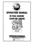
OPERATORS MANUAL .
, 3.0KW BPMG 60Hz and 50Hz
.
,SINGLE PHASE
GASOLIN
,
i
I
•
~
ENERATORS
4TH EDITION
APRIL 2009
WESTERBEKE '
CALIFORNIA
PROPOSITION 65 WARNING
Marine diesel and gasoline engine
exhaust and some of its constituents
are known to the State of California
to cause cancer, birth defects,
and other reproductive harm.
A
WARNING:
Exhaust gasses contain Carbon Monoxide, an odorless and
colorless gas. Carbon Monoxide is poisonous and can cause
unconsciousness and death. Symptoms of Carbon Monoxide
exposure can include:
-Dizziness
- Throbbing in Temples
-Nausea
- Muscular Twitching
-Headache
- Vomiting
- Weakness and Sleepiness - Inability to Think Coherently
IF YOU OR ANYONE ELSE EXPERIENCE ANY OF THESE SYMPTOMS,
GET OUT INTO THE FRESH AIR IMMEDIATELY. If symptoms persist,
seek medical attention. Shut down the unit and do not restart
until it has been inspected and repaired.
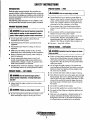
This WARNING DECAL is provided by
WESTERBEKE and should be Oxed to a
bulkhead nBar your Bnglno or gBnBrator.
WE$TERBEKEalso I'8commBnds installing
CARBON MONOXIDE DETECTORS In tho
IIvlng/sIBBplng quarters of your vessel.
ThBY al'8ln8Xpenslve and easily
obtainable at your local marino stOI'8.
-..v- WESTERBEKE
Engines & Generators
SAFETY INSTRUCTIONS
INTRODUCTION
PREVENT BURNS - FIRE
Read this safety manual carefully. Most accidents are
caused by failure to follow fundamental rules and precautions. Know when dangerous conditions exist and take the
necessary precautions to protect yourself, your personnel,
and your machinery.
The following safety instructions are in compliance with
the American Boat and Yacht Council (ABYC) standards.
A WARNING: Do not touch AC electrical connectioRS
while engine is running, Dr when connected to shore
power. Lethal voltage is present at these connections!
•
•
•
•
•
•
•
•
PREVENT ELECTRIC SHOCK
•
A WARNING: Fire can cause injury Dr death!
Do not operate this machinery without electrical
enclosures and covers in place.
Shut off electrical power before accessing electrical
equipment.
Use insulated mats whenever working on electrical
equipment.
Make sure your clothing and skin are dry, not damp
(particularly shoes) when handling electrical equipment.
Remove wristwatch and all jewelry when working on
electrical equipment.
Do not connect utility shore power to vessel's AC
circuits, except through a ship-to-shore double throw
transfer switch. Damage to vessel's AC generator may
result if this procedure is not followed.
Electrical shock results from handling a charged capacitor. Discharge capacitor by shorting tenninals together.
•
•
•
PREVENT BURNS - EXPLOSION
A WARNING: Explosions from fuel vapors can cause
injury Dr death!
•
•
PREVENT BURNS - HOT ENGINE
A WARNING: 00 not touch hot engine parts
•
•
Dr
exhaust system components_ A running engine gets
very hot!
•
Always check the engine coolant level at the coolant
recovery tank.
•
•
•
A WARNING: Steam can cause injury Dr death!
•
In case of an engine overheat, allow the engine to cool
before touching the engine or checking the coolant.
Prevent flash fires. Do not smoke or pennit flames or
sparks to occur near the carburetor, fuel line, filter, fuel
pump, or other potential sources of spilled fuel or fuel
vapors. Use a suitable container to catch all fuel when
removing the fuel line, carburetor, or fuel filters.
Do not operate with a Coast Guard Approved flame
arrester removed. Backfire can cause severe injury or
death.
Do not operate with the air cleaner/silencer removed.
Backfire can cause severe injury or death.
Do not smoke or pennit flames or sparks to occur near
the fuel system. Keep the compartment and the
engine/generator clean and free of debris to minimize the
chances of fire. Wipe up all spilled fuel and engine oil.
Be aware - diesel fuel will bum.
•
Follow re-fueling safety instructions. Keep the vessel's
hatches closed when fueling. Open and ventilate cabin
after fueling. Check below for fumes/vapor before running the blower. Run the blower for four minutes before
starting your engine.
All fuel vapors are highly explosive. Use extreme care
when handling and storing fuels. Store fuel in a well-ventilated area away from spark-producing equipment and
out of the reach of children.
Do not fill the fuel tank(s) while the engine is running.
Shut off the fuel service valve at the engine when servicing
the fuel system. Take care in catching any fuel that might
spill. DO NOT allow any smoking, open flames, or other
sources of fire near the fuel system or engine when servicing. Ensure proper ventilation exists when servicing the
fuel system.
Do not alter or modify the fuel system.
Be sure all fuel supplies have a positive shutoff valve.
Be certain fuel line fittings are adequately tightened and
free of leaks.
Make sure a fire extinguisher is installed nearby and is
properly maintained'. Be familiar with its proper use.
Extinguishers rated ABC by the NFPA are appropriate
for all applications encountered in this environment.
Engines & Generators
SAFETY INSTRUCTIONS
ACCIDENTAL STARTING
TOXIC EXHAUST GASES
A WARNING: Accidental starting can cause injury
A WARNING: Carbon monoxide (CO) is a deadly gas!
or death!
•
•
•
•
Ensure that the exhaust system is adequate to expel gases
discharged from the engine. Check the exhaust system
regularly for leaks and make sure the exhaust manifolds
are securely attached and no warping exists. Pay close
attention to the manifold, water injection elbow, and
exhaust pipe nipple.
• Be sure the unit and its surroundings are well ventilated.
• In addition to routine inspection of the exhaust system,
install a carbon monoxide detector. Consult your boat
builder or dealer for installation of approved detectors.
• For additional information refer to ABYC T-22 (educational information on Carbon Monoxide).
Disconnect the battery cables before servicing the engine!
generator. Remove the negative lead first and reconnect
it last.
Make certain all personnel are clear of the engine before
starting.
Make certain all covers, guards, and hatches are reinstalled before starting the engine.
BAnERY EXPLOSION
A WARNING: Battery explosion can cause injury
or death!
A WARNING: Carbon monoxide (CO) is an invisible
•
Do not smoke or allow an open flame near the battery
being serviced. Lead acid batteries emit hydrogen, a
highly explosive gas, which can be ignited by electrical
arcing or by lit tobacco products. Shut off all electrical
equipment in the vicinity to prevent electrical arcing during servicing.
• Never connect the negative (-) battery cable to the positive (+) connection terminal of the starter solenoid. Do
not test the battery condition by shorting the terminals
together. Sparks could ignite battery gases or fuel vapors.
Ventilate any compartment containing batteries to prevent
accumulation of explosive gases. To avoid sparks, do not
disturb the battery charger connections while the battery
is being charged.
• Avoid contacting the terminals with tools, etc., to prevent
burns or sparks that could cause an explosion. Remove
wristwatch, rings, and any other jewelry before handling
the battery.
• Always tum the battery charger off before disconnecting
the battery connections. Remove the negative lead first
and reconnect it last when disconnecting the battery.
odorless gas. Inhalation produces "u-like symptoms,
nausea or death!
•
•
•
are:
Vomiting
Dizziness
Throbbing in temples
BAnERYACID
Muscular twitching
Intense headache
Weakness and sleepiness
AVOID MOVING PARTS
A WARNING: Su"uric acid in batteries can cause
A WARNING: Rotating parts can cause injury
severe injury or death!
•
Do not use copper tubing in diesel exhaust systems. Diesel
fumes can rapidly destroy copper tubing in exhaust systems. Exhaust sulfur causes rapid deterioration of copper
tubing reSUlting in exhaust/water leakage.
Do not install exhaust outlet where exhaust can be drawn
through portholes, vents, or air conditioners. If the engine
exhaust discharge outlet is near the waterline, water could
enter the exhaust discharge outlet and close or restrict the
flow of exhaust. Avoid overloading the craft.
Although diesel engine exhaust gases are not as toxic as
exhaust fumes from gasoline engines, carbon monoxide
gas is present in diesel exhaust fumes. Some of the symptoms or signs of carbon monoxide inhalation or poisoning
or death!
When servicing the battery or checking the electrolyte
level, wear rubber gloves, a rubber apron, and eye protection. Batteries contain sulfuric acid which is destructive.
If it comes in contact with your skin, wash it off at once
with water. Acid may splash on the skin or into the eyes
inadvertently when removing electrolyte caps.
~
•
Do not service the engine while it is running. If a situation arises in which it is absolutely necessary to make
operating adjustments, use extreme care to avoid touching moving parts and hot exhaust system components.
WESTERBEKE
Engines & Generators
ii
SAFETY INSTRUCTIONS
•
•
•
•
ABYC, NFPA AND USCG PUBLICATIONS FOR
INSTALLING DIESEL ENGINES
Do not wear loose clothing or jewelry when servicing
equipment; tie back long hair and avoid wearing loose
jackets, shirts, sleeves, rings, necklaces or bracelets that
could be caught in moving parts.
Read the following ABYC, NFPA and USCG publications
for safety codes and standards. Follow their recommendations when installing your engine.
Make sure all attaching hardware is properly tightened.
Keep protective shields and guards in their respective
places at all times.
ABYC (American Boat and Yacht Council)
"Safety Standards for Small Craft"
Do not check fluid levels or the drive belt's tension while
the engine is operating.
Order from:
ABYC
3069 Solomon's Island Rd.
Edgewater, MD 21037
Stay clear of the drive shaft and the transntission coupling
when the engine is running; hair and clothing can easily
be caught in these rotating parts.
NFPA (National Fire Protection Association)
"Fire Protection Standard for Motor Craft"
HAZARDOUS NOISE
Order from:
A WARNING: High noise levels can cause hearing
NFPA
11 Tracy Drive
Avon Industrial Park
Avon, MA 02322
loss!
•
•
•
Never operate an engine without its muffler installed.
Do not run an engine with the air intake (silencer)
removed.
Do not run engines for long periods with their enclosures
open.
USCG (United States Coast Guard)
"USCG 33CFR183"
Order from:
U.S. Govemment Printing Office
Washington, D.C. 20404
A
WARNING: Do not work on machinery when you are
mentally or physically Incapacitated by fatigue!
OPERATORS MANUAL
Many of the preceding safety tips and wamings are repeated
in your Operators Manual along with other cautions and
notes to highlight critical information. Read your manual
carefully, maintain your equipment, and follow all safety
procedures.
GASOLINE ENGINE AND GENERATOR INSTALLATIONS
Preparations to install a gasoline engine or generator should
begin with a thorough examination of the American Boat and
Yacht Council's (ABYC) standards. These standards are from
a combination of sources including the USCG and the NFPA.
Sections of the AB YC standards of particular interest are:
H-2 Ventilation
H-24 Gasoline Fuel Systems
P-l Exhaust Systems
P-4 Inboard Engines
E-9 DC Electrical Systems
All installations must comply with the Federal Code of
Regulations (FCR).
Engines & Generators
iii
INSTALLATION
When installing WESTERBEKE engines and generators it is important that strict
attention be paid to the following infonnation:
CODES AND REGULATIONS
Strict federal regulations, ABYC guidelines, and safety codes must be complied with
when installing engines and generators in a marine environment.
SIPHON-BREAK
For installations where the exhaust manifold/water injected exhaust elbow is close to
or will be below the vessel's waterline, provisions must be made to install a siphonbreak in the raw water supply hose to the exhaust elbow. This hose must be looped a
minimum of 20" above the vessel's waterline. Failure to use a siphon-break when
the exhaust manifold injection port is at or below the load waterline will result in
raw water damage to the engine and possible flooding of the boat.
~
If you have any doubt about the position of the water-injected exhaust elbow relative
to the vessel's waterline under the vessel's various operating conditions, install a
siphon-break.
NOTE: A siphon-break requires periodic inspection and cleaning to ensure proper
operation. Failure to properly maintain a siphon-break can result in catastrophic
engine damage. Consult the siphon-break manufacturer for proper maintenance.
EXHAUST SYSTEM
The exhaust hose must be certified for marine use. The system must be designed to
prevent water from entering the exhaust under any sea conditions and at any angle
of the vessels hull.
Adetailed 40 page Marine Installation Manual covering gasoline and
diesel, engines and generators, is available from your WESTERBEKE
dealer.
Engines & Generators
iv
AVAILABLE FROM
YOUR WESTERBEKE
DEALER
TABLE OF CONTENTS
Parts Identification ..........................................................2
Introduction .......................................................................3
Installation ........................................................................5
Cooling System [Fresh Water Cooled Modelsj*. ............. 16
Rigging and Lifting ...................................................... 5
Location and Mounting ................................................ 5
Raw Water Discharge ................................................... 6
Raw Water Supply Hose .............................................. 6
::::::::::::::::::::: ::::
Heat Exchanger .......................................................... 18
Zinc Anode ................................................................. 18
Changing the Impeller ................................................ 16
Raw Water Pump ........................................................ 16
i~~;:;:'o;~~I~n.t:::::::::::::::::::::::::::::::::::
~
Carburetor ........................................................................ 19
OC Clrcuit/Baltery ..........................................................20
Shore Power Transfer Switch ....................................... 20
Electronic Governor .......................................................21
Engine Adjustments .......................................................22
Fuel, Engine 011 and Engine Coolant.. .......................... 7
Fresh Water Cooled Models .........................................7
Control Panels - Starting/Stopplng Procedure ........... 8
Remote Panel ............................................................... 8
Preparations for Initial Start-Up ...................................9
Adjusting the Drive Belt ............................................ 22
Oil Pressure ................................................................ 22
Engine Compression Test ........................................... 23
Water Pump Belt ........................................................ 23
Spark Plug .................................................................. 24
Thermostat [Raw Water Cooled Model] .................... 24
Valve Clearance .......................................................... 25
Replacing the Timing Belt ...................................... 25A
Troubleshooting Guide ...................................................26
AC Generator ...................................................................28
Wiring Diagram ...............................................................29
Lay-Up and RecommiSSioning ...................................... 30
Specifications .................................................................32
Metric Conversions ....................................................... .33
Standard and Metric Conversions Data ..................... 34
Suggested Spare Parts ..................................................35
Pre-start Inspection ....................................................... 9
Fresh Water Cooled Models ......................................... 9
Safety Shutdown Switches ........................................... 10
Overspeed Switch ....................................................... IO
Main Circuit Breaker ................................................. 10
Fuses ........................................................................... 10
Exhaust Temperature Switch ...................................... 10
Low Oil Switch .......................................................... 10
High Exhaust Temperature Switch ............................. 10
Maintenance Schedule .................................................. 11
Engine Lubricating 011 ................................................... 13
Changing the Oil Filter .............................................. 13
Fuel System ..................................................................... 14
Changing the Fuel Filter ............................................ 14
Fuel Pump ................................................................. 14
Cooling System ............................................................... 15
Water Pump ................................................................ 15
Water Intake Strainer .................................................. 15
Changing the Impeller ................................................ 15
*Models manufactured wilh heat exchangers for cooling )Virhfresh
waterlcoolant or raw waler cooled models that have been cOl/verted to .
fresh cooling via WESTERBEKE'S FRESH WATER COOLING KIT.
Engines & Generators
1
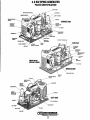
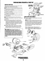
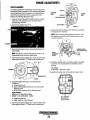
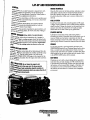
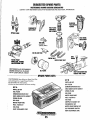
3.0 KW BPMG GENERATOR
PARTS IDENTIFICATION
~'""'''U" COIL
ENGINE SERIAL
IIGNITION .u.'nu,.~
,MODULE
SERVICE SIDE
GENEHATOR
l£CHNICAl
I FIlTER
BREAK
'CONNECTION
CO(]lANT PRESSURE
GROUND
WATER INJECTED
DRIP
WATER (COOLANT)
TEMPERATURE
SWITCH
=<-_ _ OIL DRAIN
HOSE
+---HEAT
EXCHANGER
FRESHWATER
(COOlANn MODEL
; SERVICE SIDE
WATER PUMP
IGNITION CONmOL
lOA
ACTUATOR
. LEFT SIDE
-""lJIT'ORMOUNT
Engines & Generators
2
PUMP
INTRODUCTION
These high perfonnance marine engines are products of
WESTERBEKE's long years of experience and advanced
technology. We take great pride in the superior durability and
dependable perfonnance of our engines and generators.
Thank you for selecting WESTERBEKE.
In order to get the full use and benefit from your generator,
it is important that you operate and maintain it correctly.
This manual is designed to help you do this. Please read this
manual carefully and observe all the safety precautions
throughout. Should your engine require servicing, contact
your nearest WESTERBEKE dealer for assistance.
This is your operators manual. A parts catalog is also
provided and a technical manual is available from your
WESTERBEKE dealer. If you are planning to install this
equipment, contact your WESTERBEKE dealer for
WESTERBEKE'S installation manual.
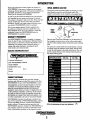
SERIAL NUMBER LOCATION
The engine ~ serial and model number are etched on a nameplate located on top of the unit (flywheel cover). The
engine's serial number is also stamped on the engine block.
•
ENGINE
SERIAL
NUMBER"
Customer Identification Card
,...,/WES,cRBEKE
A"g. M"
uu,
;:
5ER NO
~
~
~"0~~
Take the time to enter this infonnation on the illustration of
the nameplate as shown above, as this will provide a quick
reference when seeking technical infonnation and/or ordering
parts.
The generator~ serial number and model number is located
on a decal on the the generator control panel. Take the time
to enter the infonnation on the blank decal below. This will
provide a quick reference when seeking technical infonnation and/or ordering parts.
Customer Identification
MR. WESTERBEKE OWNER
MAIN STREET
HOMETOWN, USA
Ser. #
Model
Expires
PRODUCT SOFTWARE
Product software, (technical data, parts lists, manuals,
brochures and catalogs), provided from sources other than
WESTERBEKE are not within WESTERBEKE's control.
WESTERBEKE CANNOT BE RESPONSIBLE FOR THE
CONTENT OF SUCH SOFTWARE, MAKES NO WARRANTIES OR REPRESENTATIONS WITH RESPECT
THERETO, INCLUDING ACCURACY, TIMELINESS OR
COMPLETENESS THEREOF AND WILL IN NO EVENT
BE LIABLE FOR ANY TYPE OF DAMAGE OR INJURY
INCURRED IN CONNECTION WITH OR ARISING OUT
OF THE FURNISHING OR USE OF SUCH SOFTWARE.
WESTERBEKE customers should keep in mind the time
span between printings of WESTERBEKE product software
and the unavoidable existence of earlier WESTERBEKE
product software. The product software provided with
WESTERBEKE products, whether from WESTERBEKE or
other suppliers, must not and cannot be relied upon exclusively as the definitive authority on the respective product.
•
'. ",Cl
WARRANTY PROCEDURES
Your WESTERBEKE Warranty is included in a separate
folder. If, after 60 days of submitting the Warranty Registry
fonn you have not received a customer identification card
registering your warranty, please contact the factory in
writing with model infonnation, including the unit's
serial number and commission date.
PEe
Fill in the information for your own reference_ $:n
Engines & Generators
3
INTRODUCTION
ORDERING PARTS
PROTECTING YOUR INVESTMENT
Whenever replacement parts are needed, always provide the
generator and engine model and serial numbers, In addition,
include a complete part description and part number for each
part needed (see the separately furnished Parts Catalog).
Also insist upon WESTERBEKE packaged parts because
will fit or generic parts are frequently not made to the same
specifications as original equipment.
Care at the factory during assembly and thorough testing
have resulted in a WESTERBEKE generator capable of
many thousands of hours of dependable service. However the
NOTES, CAUTIONS AND WARNINGS
NOTE: Seven important steps to ensure long generator life:
As this manual takes you tluough the operating procedures,
maintenance schedules, and troubleshooting of your
generator, critical information will be highlighted by
NOTES, CAUTIONS, and WARNINGS. An explanation
follows:
• Proper engine and generator installation.
manufacturer cannot control how or where the generator is
installed in the vessel or the manner in which the unit is
operated and serviced in the field. This is up to the
buyer/owner-operator.
• An efficient weI/-designed exhaust systent that includes
an anti-siphon break to prevent water from entering the
engine.
• Changing the engine oil and oi/filters every 100 operating hours.
NOTE: An operating procedure essential to note.
A
• Proper maintenance of all engine and generator components according to the maintenance schedule in this
manual.
CAUTION: Procedures, which if not strictly
observed, can result in the damage or destruction of
the engine orgenerator.
• Use clean,jiltered unleaded fuel.
• Winterize your engine according to the "Lay-up and
A
Recommissioning" section in this manual.
WARNING: Procedures, which if not properly
• Raw Water Cooled Model - Flush the engine cooling
system according to the procedures found in this
manual.
fol/owed, can result in personal injury or loss of life.
NOTE: A carbon monoxide warning decal has been provided
by WESTERBEKE. Affix this decal in a visible location in the
engine room.
UNDERSTANDING THE GASOLINE GENERATOR
The gasoline engine driving an AC generator is in many
ways similar to a gasoline automobile engine. The cylinders
are in-line, and the engine's cylinder head has an overhead
camshaft which is belt-driven. The engine incorporates a
pressure type lubrication system, and a water-cooled engine
block.
SPARES AND ACCESSORIES
Certain spare parts will be needed to support and maintain
your WESTERBEKE generator or engine when cruising (see
SUGGESTED SPARE PARTS). Often even simple items such
as proper fuel and oil filters can be difficult to obtain along
the way. WESTERBEKE will provide you with a suggested
To a large degree, the generator's engine requires the same
spares and accessories brochure to assist you in preparing an
preventive maintenance that is required of a gasoline
on-board inventory of the proper WESTERBEKE parts.
automobile engine. The most important factors to the
generator's longevity are proper ventilation, maintenance of
the fuel system, ignition system, and cooling system.
CARBON MONOXIDE DETECTOR
WESTERBEKE recommends mounting a carbon monoxide
detector in the vessels living quarters. Carbon monoxide,
even in smaU amounts, is deadly.
The presence of carbon monoxide indicated an exhaust leak
from the engine or generator or from the exhaust
elbow/exhaust hose, or the fumes from a nearby vessel are
entering your boat.
If carbon monoxide is present, ventilate the area with clean
air and correct the problem immediately!
4
INSTALLATION
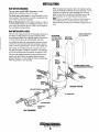
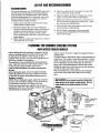
RIGGING AND LIFTING
The engine/generator is fitted with lifting eyes. Attach
wire rope or chain slings capable of supporting the
engine/generators weight to the eyes and lift the engine/generator by means of tackle attached to these slings. The lifting
eyes have been designed to carry the full weight: auxiliary
slings are not necessary.
r
0
I
14.481n (36B,mm)
D
'-""<1'_
I
EXHAUST
2.tljn (50.Bmm)
1.0. HOSE
NOTE: Rigging work is best done by someone experienced
and competent in handling machinery.
LOCATION AND MOUNTING
A solid, level mounting platform is very important for the
proper operation of your generator. Select a location that will
allow adequate space on all sides for ventilation and servicing. Locate the generator away from living quarters, and
away from bilge splash and vapors.
Refer to WESTERBEKE'S installation manual for detailed
information on installing a Marine Generator in a boat.
WATER OUTLET AND DISCHARGE
HOSES D.5in (2.7mm) 100.
AC CONNECTION
L
I-----
11.9Sin
(3~4mm)(.;,;;;i_ _ _ _ _ J~ FOUR 1/2~ BOLTS
l8.SOiI! (470mm)
USE THE PAN AS A TEMPLATEFOR
LOCATING THE PROPER MOUNTING
HOLES TO THE PLYWOOD BASE
3/4" PLYWOOD-BOLTEOIFIBERGLASSED
IN PLACE
I
160gmmJl1--------l11
1--------24.641" (625,9mm)-------<
BATTERY ATTACHMENTS
TO STARTER MOTOR
DIMENSION (INCHES AND MM)
REFER TO THE WIRING
DIAGRAM IN THIS MANUAL
(-) NEGATIVE
LEAD
Engines & Generators
5
INSTALLATION
RAW WATER DISCHARGE
When the generators location is above the loaded waterline
of the vessel during all attitudes of vessel operation, it is still
advisable to loop the raw water discharge hose at least 6
inches or more above the generator and then down to the
inlet connection on the water injected exhaust elbow.
The raw water cooled 3.0KW Generator is cooled
internally by a continuous flow of raw water.
The fresh water cooled model is cooled internally by fresh
water (coolant). This coolant is cooled by a continuous flow
of raw water (via the heat exchanger).
Both model generators use the engine cooling raw water to
NOTE: Always use quality hose with good wall integrity or
wire reinforced hose so it will maintain its shape when
looped and also provide proper mechanical support for the
hose.
cool the exhaust system as it is discharged overboard. A raw
water supply hose delivers the raw water from the engine to
the water injected exhaust elbow.
RAW WATER SUPPLY HOSE
The raw water supply hose from the discharge connection on
the engines cooling system to the inlet connection of the
water injected exhaust elbow must be looped a minimum of
12 inches (30cm) above the vessels loaded water line.
On installations where the water injected exhaust is close to
or below the vessels loaded water line, provisions must be
made to install a syphon break in the raw water supply hose.
The function of the syphon break is to stop the raw water
flow after the engine is shutdown. This flow, if not stopped,
will fill the exhaust system and possibly the engine as well.
The raw water supply hose must be looped well above the
loaded water line to allow the syphon break to function
during all attitudes of vessel operation to prevent syphoning
when the generator is not operating.
SIPHON BREAK
AVAILABLE FROM
YOUR WESTERBEKE
~~I
'"".
~
"~.'
-<-
~
~//
I
/
1/
___ - - - ' ,
~/
\1"
/--- ....... "'-1-.. . . "-""- /'
,..... -
/
RAW WATER
SUPPLY HOSE
_
~k:§
WHEN A SIPHON BREAK
IS NOT REQUIRED
/---,
/
___ , \
,_-
.;.~,
\.
L
/
"~,I
\' \
\"
I
\
1I
I
I,
I
I
I
I
I
I
1
I
I
I
I
~
I
'
:,~,/1
) [ 1I
I I
I
'I
I
I
I
J
I
I
I
.
"
I
WATER
INJECTED
EXHAUST
I
!
I
I
I
1
I
t!
I
I
I
I
J
r{ "
I
I
~1
I
I
i
:
I
I
OPENING (l/BNPT)
FOR MEASURING BACK PRESSURE
'.1.111;",,"
EXHAUST
OVERBOARD
EXHAUST SYSTEM
DRAIN HOSE
:"';~;:-_GOGILANI
DRAIN
"'=''----·R''W WATER
'DRAIN
HEAT EXCHANGER
""" WESTERBEKE
Engines & Generators
6
FUEL, ENGINE OIL AND ENGINE COOLANT
ENGINE OIL
GASOLINE
Use a heavy duty engine oil with an API classification of SJ.
Change the engine oil and filter after an initial 50 hours of
break-in operation, and every 100 hours of operation
thereafter.An oil viscosity of SAE 15W-40 is recommended
for this engine in all conditions.
A CAUTION: Only use unleaded fuel with an octane
rating of 8S or higher. Leaded fuel will cause serious
harm to your engine and violate your warranty.
Care Of The Fuel Supply
A CAUTION: 00 not allow two or more brands of
Use only clean diesel fuel! The clearance of the components
in your fuel injection pump is very critical; invisible dirt
particles which might pass through the filter can damage
these finely finished parts. It is important to buy clean fuel,
and keep it clean. The best fuel can be rendered
unsatisfactory by careless handling or improper storage
facilities. To assure that the fuel going into the tank for your
engine's daily use is clean and pure, the following practice is
advisable.
ensine oil to mix. Each brand contains its own additives;
additives of different brands could react in the mixture
to produce properties harmful to your engine.
ENGINE COOLING
The 3.0KW Generator is cooled by raw water. This raw
water cooling system is described on the COOLING SYSTEM page.
Purchase a well-known brand of fuel.
A fresh water cooling system kit is available from
WESTERBEKE that converta a raw water cooled model to a
fresh water system. Contact your WESTERBEKE dealer for
Install and regularly service a good, Coast Guard approved
metal bowl type filter/water separator between the fuel tank
and the engine.
infonnation.
FRESH WATER COOLED MODELS
The 3.0KW Generator is also manufactured as a fresh water
cooled model. For operating instructions, refer to FRESH
WATER COOLED MODELS in this manual.
~
WESTERBEKE
Engines & Generators
7
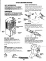
CONTROL PANEL· START/STOP PROCEDURE
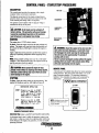
DESCRIPTION
lOA FUSE
~~.
The control panel provides the operator with a simple
stop/start rocker switch and a hourmeter.
The plug-in connections for the engine wiring harness,
governor sensor and remote panel are located on the side
of the control panel along with a 10 amp fuse.
The ignition control module with it's plug-in wiring is
mounted on the top of the panel.
A CAUTION: All AC loads must be switched off
SWITCH
before starting. This precaution will prevent damage
caused by unanticipated operation of AC machinery
and will prevent a cold engine from starting
MAIN CIRCUIT
BREAKER
STARTING
The engine has a 12 VDC electric starter.
Th Start: Press the rocker switch to the start position and
release. The engine will crank and start electronically and
the switch will show a RED light to indicate the engine is
running.
Apply a light load to the generator and allow the engine to
warm up to operating temperature before applying heavy
loads.
A WARNING: Should the engine fail to start once the
start switch has been depressed, a crank limit circuit
will disengage the starter and stop the starting cycle.
This will occur after approximately 15 seconds of
cranking with no start.
This Is to prevent prolonged cranking without the engine
starting which can result In the exhaust system filling
with water and backing Into the engine.
IIOTE: Some unstable running may occur in a cold engine
condition. This should smooth out as the engine wanns up
and the generator loads are applied.
A
the
CAUTION: I18rt11 operate engine for long
perItIds of time wltho/lt an amperage load being applied,
othetwlse CIIIboII build-up may o(:cur which. can cause
SIWtJtW danlage to the engine.
REMOTE PANEL
A remote panel is available that allows for remote operation
of the generator. The panel comes with either a IS' or 30'
plug-in extension harness. The start/stop sequence is
identical. Once installed, the engine can be operated by
either panel.
STOPPING
Th Stop: Press the rocker switch to stop and release. The
engine will shutdown and the, LED light will tum off.
!V\T!WESTERBEKE
•
START
GENERATOR OPERATION
SlARf: Depreu swi Ich 10 START
posilion. START LEO wi II
lile. engine will cronk.
o
RUH LEO will remain on
when engine is running.
STOP: Depress swilch 10 STOP
o
NOTE: Holding the start button
depressed will keep the start
posilio,. ['gi,e will slop.
RUH LEO wi" lurn off.
circuit engaged.
STOP.
, ENGINE STOfllS7'ART DECAL
Abnonnal Stop
(refer to SAFETY SHUTDOWN SWITCHES)
An abnormal stop is one in which the generator ceases to run
and comes to a stop as a result of an operating fault which may
·cause damage to the engine, the generator, or create an unsafe
operating condition.
~
WESTERBEKE
Engines & Generators
8
PREPARATIONS FOR.INITIAL START-UP
PRESTART INSPECTION
FRESH WATER
Before starting your generator set for the first time or after a
prolonged layoff, check the following items:
•
Make certain the cooling water thru-hull petcock is open.
•
Check the engine oil level: add oil to maintain the level at
the full mark on the dipstick.
•
Check the fuel supply and examine the fuel filter/separator
COOLED MODELS
bowls for contaminant's.
•
Check the DC electricall\;ystem. Inspect wire connections
and battery cable connections.
•
Check load leads for correct connection as specified in the
wiring diagrams.
•
Examine air inlet and outlet for air flow obsttuctions.
FRESH IIfAT':"
Be sure no other generator or utility power is connected to
•
•
load lines.
•
Be sure that in power systems with a neutral line that
the neutral is properly grounded (or ungrounded) as the
system requires, and that the generator neutral is properly
connected to the load neutral. In single phase systems an
incomplete or open neutral can supply the wrong line-toneutral voltage on unbalanced loads.
•
Visually examine the unit. Look for loose or missing
parts, disconnected wires, unattached hoses, and check
threaded connections. Search for any gasoline leaks.
Check the coolant level in both the plastic recovery tank
and at the manifold.
NOTE: After the initial running of the generator, the air in
the engine ~ cooling system will be purged to the coolant
recovery tank. Open the air bleed petcock to ensure thot
the cooling system is purged of air. After shutdown and
after the engine has cooled, the coolant from the recovery
tank will be drawn into the engine ~ cooling system to
replace the purged air.
Before subsequent operation of the generator, the
engine ~ manifold should be topped off, and the coolant
recovery tank may need to be filled to the MIIX level.
A CAUTION: When starting the generator, it is
recommended that all AC loads, especially large motors,
be switched OFF until the engine has come up to speed
and, in cold climates, starts to warm up. This precaution
will prevent damage caused by unanticipated operation
of the AC machinery and will prevent a cold engine from
stalling.
OIL
, - . - - - - - Clll FIlTER
INCOMING
FUE:
CONNEcrs
TOWArER
PUMP
FUll
...v'
WESTERBEKE
Engines & Generators
9
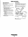
SAFETY SHUTDOWN SWITCHES
EXHAUST TEMPERATURE SWITCH
SAFETY SHUTDOWN SWITCHES
An exhaust temperature switch located at the base of the
exhaust elbow sensors an excessive exhaust temperature
(an inadequate supply of cooling water). A temperature
aboye 2400 F will shut the engine down. Inspect the cooling
This engine is protected by three shutdown switches and
two fuses. Should a shutdown occur, do not attempt to
restarl without finding and correcting the cause. Refer to
the heading Engine sliirts, runs and then shuts down in the
ENGINE TROUBLESHOOTING section of this manual.
system, water pump, pump belt, seacock, water strainer,
water hoses, etc. This switch will reset itself when the
exhaust cools.
OVERSPEED SWITCH
The overspeed PC board inside the control panel will shut
the engine down if the engine speed (RPM'S) exceeds the
operating speed required to run the generator. The oyerspeed
PC board will reset itself once the engine shuts down.
EXHAUST
ELBOW
FUSE
TEMPERATURE
SWITCH
SWITCH
LOW DlL SWITCH
Located just to the right' of the oil filter, this switch sensors
the engine's oil pressure if the oil pressure falls to below
5 psi. This switch will shut the engine down. Check the
angle of operation, dipstick oilleyel and oil filter. The switch
will reset itself.
LOW OIL PRESSURE SWITCH
CONTROL
PANEL
IM-r---MA,IN CIRCUIT
BREAKER
. HIGH WATER TEMPERATURE SWITCH
(Fresh Water Cooled Model)
MAIN CIRCUIT BREAKER AC
The main circuit breaker at the control panel will
automatically disconnect the AC power if there is an
electtical overload.
This circuit breaker should be manually switched off
when servicing the engine/generator to ensure that no
power is coming into the boat. The breaker is reset
manually.
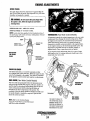
A high water temperature switch is located at the thermostat
housing. Normally closed, this switch, should the fresh water
coolant's operating temperature reach approximately 210"1'
(99'C), will open and shut the engine down. This switch
resets itself at 195"1' (107'C) .
........,~==-
OC()OL,qNTRECOVERY TANK
FUSES
A lOA fuse located on the side of the control panel protects
the DC electtical wiring. If an electtical overload occurs the
fuse will blow and shut the engine down.
An 20A in-line fuse protects the battery charging circuit. If
this fuse fails, the engine will continue to run but the battery
will not be charging.
THERMqSTAT
HOUSING
~
-=t) ) lP»=
lOA FUSE
20A FUSE
BATTERY CHARGING
Engines & Generators
10
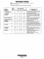
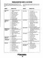
MAINTENANCE SCHEDULE
A WARNING: Never aUempt to perform any service while the engine is
running. Wear the proper safety equipment such as goggles and gloves, and
use the co"ect tools for each job. Disconnect the baUery terminals when
servicing any of the engine's DC electrical equipment.
NOTE: Many of the following maintenance jobs are simple but others are more
difficult and may require the expert knowledge of a service mechanic.
SCHEDULED
MAINTENANCE
CHECK
EACH
DAY
HOURS OF OPERATION
50
100
250
500
750 1000 1250
EXPLANATION OF SCHEDULED
MAINTENANCE
Fuel Supply
0
Unleaded gasoline with octane rating of 89 or
higher
Fuel/Water Separator
0
Check for water and dirt in fuel (drain/replace filter
if necessary).
Engine Oil Level
0
0
Maintain at the full level.
Drive Belt
Inspect and adjust at first 25 hours. Measure
spring tension. Inspect edges for wear. Replace
every 1000 hours.
weekly
Visual Inspection of Engine
0
Spark Plugs
NOTE: Please keep engine surface clean. Dirt
and oil will inhibit the engine's ability to
remain cool.
Generator
0
0
Fuel Filler
0
Starting Banerles
(and House Baneries)
0
0
0
0
0
0
0
0
0
0
Check gap. Inspect for burning and corrosion.
0
0
0
0
0
Initial change at 50 hrs, then change every 250 hrs.
Check that AC connections are clean and secure
with no chafing - see GENERATOR INFORMATION
for additional information.
Every 50 operating hours check electrolyte levels
and make sure connections are very tight. Clean off
excessive corrosion.
0
weekly
Engine Oll/Fllter
0
• Adjust the Valve
Clearances
0
Carburetor Air Screen
(Flame Arrester)
0
Exhaust System
0
Engine Hoses
Engine Zinc Anode
0
Check for fuel, oil and water leaks. Inspect wiring
and electrical connections. Keep bolts & nuts tight.
Check for loose belt tension.
0
0
0
0
0
0
0
0
Initial engine oil & filter change at 50 hrs., then
change both every 100 hours.
Initial adjustment at 50 hours, then every 500 hours .
0
0
0
0
0
0
Clean at 50 ours, then every 100 hours.
0
0
0
0
0
Initial check at 50 hrs., then every 250 hrs. Inspect
for leaks. Check siphon brake operation. Check the
exhaust elbow for carbon and/or corrosion buildup
on inside passages; clean and replace as necessary.
Check that all connections are tight.
0
0
0
0
0
0
Hose should be hard & tight. Replace if soft or
spongy. Check and tighten all hose clamps.
0
0
0
0
0
0
Inspect and replace if necessary.
0
'WESTERBEKE recommends this service be performed by an authorized mechanic.
~
WESTERBEKE
Engines & Generators
11
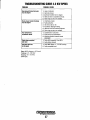
MAINTENANCE SCHEDULE
NDTE: Use the engine hour meter gauge to log your engine hours or record your
engine hours by running lime.
"WESTERBEKE recommends this service be pertormed by an authorized mechanic.
SCHEOULED
MAINTENANCE
CHECK
EACH
DAY
HOURS OF OPERATION
50
100
Raw Water Pump
250
0
500
EXPLANATION OF SCHEDULED
MAINTENANCE
750 1000 1250
Remove
the
pump
cover and inspect the impeller for
0
0
At 800 operating hours,
wear. Replace if needed. Also inspect the a-rings.
Lubricate both when reassembling .
disassemble and inspect
. for overhaul.
Fresh Water Pump
(if appllca~le)
Raw Water Cooling System
Drain, flush, and refill cooling system with
appropriate antifreeze mix.
0
0
0
0
"Starter Motor
"Engine Cylinder
Compression
At winter lay-up or if the generator is to be idle for
more than 3 months, flush with fresh water.
0
Fresh Water Cooling System
(if applicable)
Heat Exchanger
Remove raw water pump to access the fresh water
pump. Remove the cover and inspect the impeller
and inside cover for wear. Also inspect the sealing
a-rings.
0
0
0
"Exhaust Elbow
0
Clean or replace anode. Open heat exchanger end
cap and clean out debris. Remove every 1000
hours for professional cleaning and pressure testing.
0
0
Check solenoid and motor for corrosion. Remove and
lubricate. Clean and lubricate the starter motor pinion
drive.
0
0
Incorrect valve clearance will result in poor engine
pertormance. Check compression pressure and timing
and adjust valve clearances.
0
0
0
Test exhaust elbow for casting integrity. Replace if
casting is corroded or deteriorated.
0
WARNING: A defective exhaust elbow can cause
carbon monoxide leakage!
,..y-
WESTERBEKE
Engines & Generators
12
ENGINE LUBRICATING OIL
DESCRIPTION
WIPE THIS SURFACE
CLEAN BEFORE
IIV"'~LL.IIV" FILTER
Use a heavy duty engine oil with an API classification of SJ.
Change the engine oil after an initial 50 hours of break-in
operation, and every 100 hours of operation thereafter. For
recommended oil viscosity, see the following chart:
Operating Temperature
Oil Viscosity
Above 68' F (20' C)
SAE 30, 10W-30 or 15W-4D
41' - 68' F (5'-20' C)
SAE 20 or 1OW-3D
Below 41' F (5' C)
SAE 10W-30
A
OIL FILTER ASSEMBLY
PRESSURE SWITCH
OIL FILTER
WRENCH
APPLY CLEAN
TO GASKET
OIL FILTER
CAUTION: Do not allow two or more brands of
engine oil to mix. Each brand contains its own addi·
tives: additives of different brands could react in the
mixture to produce properties harmful to your engine.
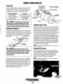
CHANGING THE OIL FILTER
When removing the used oil filter, you may find it helpful to
punch a hole in the upper and lower portion of the old filter
to drain the oil into a container before removing it. This helps
to lessen spillage. An automotive filter wrench should be
helpful in removing the old oil filter. Place some paper towels
and a plastic bag around the filter when unscrewing it to catch
any oil that's in the filter. Inspect the old oil filter as it is
removed to make sure that the rubber sealing gasket comes
off with the old oil filter. If this rubber sealing gasket remains
sealed against the oil filter adapter, gently remove it. When
installing the new oil filter element, wipe the filter gasket's
sealing surface on the oil filter adapter free of oil and apply a
thin coat of clean engine oil to the rubber sealing gasket on
the oil filter. Screw the filter onto the threaded oil filter stub,
and tighten the filter firmly by hand.
CHANGING THE ENGINE OIL
The engine oil should be wann. Remove the oil drain hose
from its attachment bracket and lower it into a container and
allow the oil to drain, or attach a pump to the end of the drain
hose and pump the old oil out. Make sure the oil drain hose
is properly secured in its holder after all of the old oil has
been drained.
9/16"
~f~~~O;'IL DRAIN
NOTE: Use genuine WESTERBEKE oil filters.
Generic filters
are not recommended.
r-~~{I~--~---------------.
A WARNING: Used engine oil contains harmful
REFILLING THE OIL SUMP
contaminants. Avoid prolonged skin contact. Clean skin
and nails thoroughly using soap and water. Launder or
discard clothing or rags containing used oil. Discard
used oil properly.
Add fresh oil through the valve cover. After refilling the oil,
run the engine for a few moments while checking the engine's
oil pressure. Make sure there is no leakage around the new
oil filter or from the oil drain system, and then stop the
engine. Then check the quantity of oil with the lube oil
dipstick. Fill to the FULL mark on the dipstick.
NOTE: It is impol1ant, because of the shallow oil sump to
keep the oil level at the full mark.
Always observe the old oil as it is removed. A yellow/gray
emulsion indicates the presence of water in the oil. Although
this condition is rare, it does require prompt attention to
prevent serious damage. Call a competent mechanic if water
is present in the oil. Water present in the oil can be the result
of a fault in the exhaust system attached to the engine andlor
a siphoning through the water cooling circuit into the
exhaust, filling it up into the engine.
.... WESTERBEKE
Engines & Genera/ors
13
FUEL SYSTEM
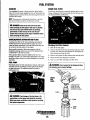
GASOLINE
ENGINE FUEL FILTER
Use unleaded 89 octane or higher gasoline. When fueling,
follow U.S Coats Guard regulations, close off all hatches and
companionways to prevent fumes from entering the boat, and
ventilate after fueling.
Periodically check the fuel connections and the filter bowl for
leakage. Change the filter element after the first 50 hours. See
the MAINTENANCE SC,HEDULE.
NOTE: The generator compartment should have a gasoline
fume detectorlalarm properly installed and working.
A WARNING: Shut off the fuel valve at the tank
when servicing the fuel system. Take CBlB In catching
any fuel that may spill. DO NOT allow any smoking,
open lIames or other sources of fire near the fuel
system when servicing. Ensun: proper ventilation exists
when servicing the fuel system.
GASOUNE/WATER SEPARATOR AND FILTER
A primary fuel filter of the water separating type must be
installed be~een the fuel tank and the engine to remove
water and other contaminant's from the fuel before they can
be carried to the fuel system on the engine.
Most installers include a filter/water separator with the
installation package as they are aware of the problems that
contaminant's in the fuel can cause.
These gasoline fiiters must have metal bowls (not "seethrough") to meet U.S . .coats Guard requirements. The metal
bowls have drain valves to use when checking for water and
impurities.
Changing the Filter Element
1. Shut off the fuel supply.
2, Unscrew the filter bowl from the housing and allow bowl
to come away from the housing.Remove and replace the
filter element and clean iIie bowl.
3. Remove and replace the filter element and clean the bowl
4. Inspect both O-rings. Replace if necessary.
5. Press on a new filter and replace the filter bowl.
FUEL PUMP
A WARNING: Fuel is present in the hosing and lines.
Periodically check the fuel connections to and out of the pump
and make sure that no leakage is present and that the fittings
are tight and secure. The engine mounted fuel pump is
Use
care to prevent spillage
maintenance free.
ENGINE
FUEL
FILTER
LUBRICATE WITH
CLEAN FUEL AND
PRESS THE FILTER
ON OVER THE a-RING
A
WARNING: Fuel leakage at the fuel pump or its
connections is a fire hazard and should be corrected.
Make sure proper ventilation exists whenever servicing
fuel system components.
...v"
WESTERBEKE
Engines & Generators
14
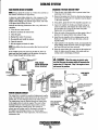
COOLING SYSTEM
RAW WATER INTAKE STRAINER
CHANGING THE RAW WATER PUMP
NOTE: Always install the strainer at or below the waterline so
the strainer will always be self-priming.
1. Close the raw water intake valve to prevent water from
syphoning from the pump.
2. Remove the pump cover. Note the direction the blades are
turned (when installing the new impeller, bend the blades
in the same direction).
A clean raw water intake strainer is a vital component of the
engine's cooling system. Include a visual inspection of this
strainer when making your periodic engine check. The water
in the glass should always he clear.
Perfonn the following maintenance after every 100 hours of
operation:
1. Close the raw water seacock.
2. Remove and clean the strainer filter.
3. Clean the glass.
4. Replace the washer if necessary.
S. Re-assemble and install the strainer.
6. Open the seacock.
7. Run the engine and check for leaks.
3. Using pliers, grasp the hub of the impeller and pull it out.
4. Inspect the impeller by bending each blade looking for
cracks at each base. Also inspect the inside of the cover,
the cam plate, the O-ring, and the inner wear plate.
Replace any worn components.
S. Wipe the inside of the pump dry and then apply a film of
glycerin to the pumps interior and sealing O-ring.
6. Install the n~w impeller with a rotating motion so the
blades are "working" in the same direction as the old
impeller blades.
7. Apply glycerin to the impeller, install, and reassemble the
pump making certain the cover screws are tight. Replace
any hoses that may have been removed.
8. Open the water intake valve, start and run the engine and
check for leaks around the pump. Also make sure raw
cooling water is discharging overboard.
NOTE: Also follow the above procedure after having run hard
aground.
If an overheat occurs, the cause may be that silt, leaves or
grass may have been caught up in the strainer, slowing the
flow of water through the cooling system
A
"'O!'~'
:,'
WARNING: When the engine is started, make
sure that the pump is pumping within 30 seconds after
engine start. If it does not, "stop" the engine at once
and correct the problem.
FUEL FILTER!
WATER SEPARATOR
IOwner Installed)
RAW WATER
PUMP
COVER
INSPECT THE INSIDE
OF THE COVER FOR
WEAR. APPLY A THIN
COAT OF GLYCERIN AT
ASSEMBLY
WATER COOLING CIRCUIT
The water flow is created by a positive displacement impeller
pump. This pump draws water directly from the water source
(ocean,lake, or river) through a hose to the water strainer.
The water passes from the strainer through the water pump
to the engine where it cools the engine. The water is then
discharged into the water-injected exhaust elbow, mixing
with and cooling the exhaust gasses. This mixture of
exhaust gas and cooling water is discharged overboard by
the engine's gas discharge pressure. An internal engine
thennostat controls the water temperature. This thermostat is
maintenance free.
~
THE IMPELLER HUB SCREW
FITS INTO THE SLOT IN
THE SHAFT
IF ANY IMPELLER BLADES
ARE MISSING. THEY
BE FOUND TO PREVENT
BLOCKAGE IN THE
COOLING CIRCUIT.
WIPE THIS SURFACE
CLEAN BEFORE
INSTALLING THE
COVER
SCREW
FROM RAW WATER
STRAINER
WESTERBEKE
Engines & Generators
15
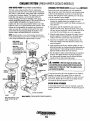
COOLING SYSTEM [FRESH WATER COOLED MODELS]
RAW WATER PUMP (Fresh Water Cooled Models)
CHANGING THE FRESH WATER (Coolant Pump) IMPELLER
The fresh water cooled model has the raw water pump
mounted above the fresh water (coolant) pump as illustrated.
This pump is a self-priming, rotary pump with a non-ferrous
housing and a Neoprene impeller. The impeller has flexible
blades that wipe against a curved cam plate within the
impeller housing, producing the pumping action. On no
account should this pumP be run dry. There should always be
a spare impeller and impeller cover gasket aboard (an
impeller kit). Raw water pump impeller failures occur when
lubricant (water) is not present during engine operation. Such
Remove the cover screws and the cover will separate the
upper pump (raw water) from the fresh water (coolant) pump
as shown in the illustration. Close the raw water thru hull
seacock. This will prevent water syphoning out of the pump
while the impeller is being changed.
failures are not warrantable, and operators are cautioned to
make sure water flow is present at start-up: The raw water
2. Using pliers, grab the impeller hub and withdraw the
impeller from the pump. Inspect the inside of the pump,
the cam, the inner wear plate, and the inside surface of the
cover plate for wear. Replace any worn components.
1. Remove the wear plate to expose the impeller. Notice the
direction the impeller blades are working in so as to
install the replacement impeller with blades working in the
same direction.
pump should be inspected periodically for broken or tom
impeller blades. See MAINTENANCE SCHEDULE.
3. Wipe the inside surface of the pump dry. Apply a film of
glycerin supplied in the impeller kit to the inside pump
surfaces and to the exposed area of the shaft lip seaL
NOTE: Should a failure occur with the pumps internal parts
(seals and bearings) it may be more cost efficient to purchase
a new pump and rebuild the original pump as a spare.
4. Install the new impellers with a rotating motion so the
blades are working in the same direction as those of the
removed impeller.
PUMP COVER
INSPECT THE INSIDE
SURFACE FOR WEAR.
5. Apply glycerin to the O-ring, impeller, gasket, the wear
plate and assemble into the pump housing. Reassemble the
upper pump (raw water) making certain the fasteners are
tight. Re-install any hoses that were removed.
IMPELLER
FIT THE HUB SCREW
INTO THE SHAFT SLOT
WHEN ASSEMBLING. COAT
THE IMPELLER AND
WITH GLYCERIN
6. Run the engine to make certain both pumps are operating
properly. The engine should run at proper temperature.
raw water should discharge from the exhaust and there
should not be any leaks around the pumps.
A
WARNING: When the engine is started, make
sure that the pump is pumping within 30 seconds after
engine start. If it does not, "stop" the engine at once
and correct the problem.
. To increase the service life of the impeller, do not install the
impeller in the pump if the engine will be in storage for
longer than 3 months. Store the impeller in a dark, cool, and
dry location. Replace the cover plate on the pump securely
and ensure the thru hull seacock is closed.
WATER INTAKE STRAINER
A water intake strainer (raw water) is a required component
when the generator is installed. Refer to the previous page for
details.
O·RING
WIPE THIS SURFACE CLEAN
BEFORE INSTALLING THE
COVER
DUAL PUMPS (FRESH WATER COOLED MODELS)
Engines & Generators
16
COOLING SYSTEM [FRESH WATER COOLED MODELS]
FRESH WATER CODLING CIRCUIT
Fresh water coolant is pumped through the engine by a
circulating pump, absorbing heat from the engine, The
coolant then passes through the thermostat into the manifold,
to the heat exchanger where it is cooled and returned to the
engine block via the suction side of the circulating pump,
When the engine is started cold, external coolant flow is
prevented by the closed thermostat (although some coolant
flow is bypassed around the thermostat to provide coolant
circulation in the engine block). As the engine warms up, the
thermostat gradually opens, allowing full flow of the engine's
coolant to flow unrestricted to the external portion of the
cooling system.
NOTE: Periodically check the condition of the pressure cap.
Ensure that the upper and lower rubber seals are in good
condition and check that the vacuum valve opens and closes
tightly. Carry a spare cap.
CHANGING COOLANT
ENGINE COOLANT
The engine's coolant must be changed according to the
MAINTENANCE SCHEDULE. If the coolant is allowed to
become contaminated, it can lead to overheating problems.
WESTERBEKE recommends a mixture of 50% antifreeze
and 50% distilled water. Distilled water is free from the
chemicals that can corrode internal engine surfaces.
The antifreeze performs a double duty. It allows the engine to
run at proper temperatures by transferring heat away from
the engine to the coolant and lubricates and protects the
A CAUTION: Proper cooling system maintenance is
critical; a substantial number of engine failures can be
traced back to cooling system corrosion.
cooling circuit from rust and corrosion. Look for a good
quality antifreeze that contains Supplemental Cooling
Additives (SCA'S) that keep the antifreeze chemically
balanced, crucial to long term protection.
Drain the engine coolant by loosening the drain plug on the
heat exchanger and opening pressure cap. Also loosen the air
bleed petcock on the top of the heat exchanger
NOTE: Look for the new environmentally friendly long lasting
antifreeze that is now available.
A WARNING: Beware of the hot engine coolant.
The recommended 50/50 mixture will protect the engine
Wear protective gloves.
against the most extreme temperature. The antifreeze mixture
will also retard rust within the engine and add to the life of
the circulating pump impeller and seals.
Refilling the Coolant
A proper 50/50 mixture as recommended will protect the
engine coolant to temperatures of - 40°F.
Tighten the heat exchanger drain plug and slowly pour clean,
premixed coolant in thru the coolant fill. Leave the heat
exchanger air bleed petcock loose to allow trapped air to
escape. As the filling continues, start and run the engine.
Close the air bleed petcock and fill until coolant tops off at
the coolant fill. Install the pressure cap.
Remove the cap on the coolant recovery tank and fill with
coolant mix to halfway between LOW and MAX and replace
the cap. Run the engine and observe the coolant expansion
flow into the recovery tank.
After checking for leaks, stop the engine and allow it to cool.
Coolant should draw back into the cooling system as the
engine cools down. Add coolant to the recovery tank if
needed and make certain the coolant is topped off at the
pressure cap. Clean up any spilled coolant.
Coolant Recovery Tank
The coolant recovery tank allows for the expansion and contraction of the engines coolant during engine operation without introducing air into the system. This recovery tank is
provided with fresh water cooled models and with the fresh
water coolant conversion kit and must be installed before
operating the engine.
NOTE: This tank, with its short run of plastic hose, is best
located at or above the level of the engine's manifold.
~
WESTERBEKE
Engines & Generators
17
COOLING SYSTEM [FRESH WATER COOLED MODELS]
TO WATER COOLED
EXHAUST
THERMOSTAT
Fresh water cooled 3.0KW generators have a thermostat that,
controls the coolant temperature as the coolant continuously
flows through the closed cooling circuit. When the engine is
first started, the closed thermostat prevents coolant from
flowing (some coolant is around the thermostat to provide
coolant circulation in the engine block). As the engine wanns
up, the thermostat gradually opens. The thermostat is
accessible and can be checked, cleaned, or replaced easily.
Carry a spare thermostat and gasket
Replacing the Thermostat
A~_--~COOLANT
Remove the cap screws and disassemble the thermostat
housing as shown. When installing the new thermostat and =~r\'\::""
gasket, apply a thin coat of sealant on both sides of the
gasket before pressing it into place.
Run the engine and check for normal temperatures and that
there
leaks around the thermostat housing/gasket.
DRAIN
f::::':....:fr(-·----~--RAW WATER DRAIN
ZINC ANODE
A zinc anode. or pencil, is located in the raw water cooling
circuit within the heat exchanger. The purpose of the zinc
anode is to sacrifice itself to electrolysis action taking place
in the raw water cooling circuit, thereby reducing the effects
of electrolysis on other components of the system. The
condition of the zinc anode should be checked monthly and
the anode cleaned or replaced as required. Spare anodes
should be carried on board.
NOTE: Electrolysis is the result of each particular installation
and vessel location; not that of the engine.
GASKET
ADD SEALANT
AT ASSEMBLY
THERMOSTAT
HOUSING
NEW
HEAT EXCHANGER
CLEAN & REUSE
If the zinc pencil needs replacement, hold the hex boss into
which the zinc pencil is threaded with a wrench while
loosening the anode with another wrench. This prevents the
hex boss from possibly tearing off the exchanger shell. After
removing the zinc, note, the condition of it. If the zinc is in
poor condition, there are probably zinc flakes within the
exchanger. Remove the end of the heat exchanger and clean
the inside of all zinc debris. Always have a spare heat
exchanger end gasket in case the present one becomes
damaged when removing the end cover. Replace the gasket
(refer to your engine model's heat exchanger end gasket part
number), a-ring, cover, and install a new zinc anode.
Cool raw water flows through the inner tubes of the heat
exchanger. As the engine coolant passes around these tubes,
the heat of the internal engine is conducted to the raw water
which is then pumped into the exhaust system and
discharged. The engine coolant (now cooled) flows back
through the engine and the circuit repeats itself.
The engine coolant and raw water are independent of each
other; this keeps the engine's water passages clean from the
harmful deposits found in raw water.
Heat Exchanger Service
After approximately WOO hours of operation, remove, clean
and pressure test the engine's heat exchanger. (A local
automotive radiator shop should be able to clean and test the
heat exchanger.)
NOTE: The threads of the zinc anodes are pipe threads and do
not require sealant. Sealant should not be used as it may
insulate the zinc from the metal of the heat exchanger
housing preventing electrolysis action on the zinc.
NOTE: Operating in silty and/or tropical waters may require
that a heat exchanger cleaning be peifonned more often than
eVelY 1000 hours.
~
REPLACE
WESTERBEKE
Engines & Generators
18
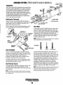
CARBURETOR
DE·RICHENING
CARBURETOR
BOWL
The carburetor is a single barrel, side-draft type with a
cleanable metal screen air intake filter/spark arrester.
The choke is operated by a 12 VDC solenoid. The choke
solenoid is activated when the start switch is depressed and is
controlled by the r.C.M.
Air Screen}Flame Arrester
The air screen can easily be removed. Clean after the first 50
hours of operation and every 100 hours from then on. Clean
the air screen in a water soluble cleaner such as GUNK.
I SCRE
Fuel Overflow Chamber
Excess fuel drains into the fuel overflow chamber but is
drawn out again at start-up. This chamber should be kept free
of contaminates. Cleaning every 250 operating hours should
be sufficient unless there is a fuel problem.
ACTUATOR
Oe-Richening Valve
The de-richening valve closes off a fuel port that is supplying
additional fuel on a cold start after start up. This is a thermal
electric device that slowly moves a needle outward when
DC power is applied after start up to close this fuel port.
To check this valve, remove from the carburetor (cold) and
apply DC voltage across its electrical connections. The
devise should get hot and the needle will slowly move
outward. the devise will remain hot during engine operation
FUEL UVtl1tLUIW
CHAMBER
Carburetor Bowl Drain
A bowl drain slotted plug is located on the lower right corner
of the carburetor bowl. This is located just inboard of the
actuators ball joint/clevis.
Idle Mixture Jet
The idler mixture jet is factory adjusted and plugged.
DC
NOTE: Ball joint linkage between actuator alld thmllie. Lube
periodically (use graphite lubricant) to maintain smooth
operation.
DE·RICHENING
VALVE
MIXTURE
·.rT"",," lEVER
KEEP THE LINKAGE
WELL LUBRICATED
Engines & Generators
19
DC CIRCUIT/BATTERY
DESCRIPTION
Testing the Circuit
The DC Circuit functions to start, operate and stop the
generator's engine. The circuit is best understood by
reviewing the DC Wiring Diagram and Wiring Schematic,
The engine's DC wiring is designed with three simple basic
circuits: start, run, and stop.
If the battery is not charging, check the fuse. To test the
circuit, remove the fuse and test with a voltmeter between the
fuse holder connection and ground. With the engine running,
it should indicate 13·14 volts. If only battery voltage is
indicated, check the terminal connections at the battery.
The engine has a 12 volt DC electrical control circuit that is
shown on the Wiring Diagrams. Refer to these diagrams
when troubleshooting or when servicing the DC electrical
system on the engine.
Battery Maintenance
A CAUTION: To avoid damage to the battery charging
circuit, never shut off the engine battery switch while
the engine is running. Shut off the engine battery switch,
however, to avoid electrical shorts when working on the
engine's electrical circuit.
Specifications
Review the manufacturer's recommendations and then
establish a systematic maintenance schedule for your
engine's starting batteries and house batteries.
• Check the electrolyte level and specific gravity with a
hydrometer.
• Use only distilled water to bring electrolytes to a proper
level.
• Make certain that battery cable connections are clean and
tight to the battery posts (and to your engine).
• Keep your batteries clean and free of corrosion.
The minimum recommended capacity of the dedicated battery
used in the engine's 12 volt DC control circuit is 600·900 CCA.
Battery Charging Circuit
The engine supplies a continuous 7 amp charge from the
voltage regulator to the engine's battery. This charge passes
thru an 8 amp fuse (and the ships battery switch).
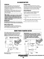
SHORE POWER TRANSFER SWITCH
If the installer connects shore power to the vessel's AC
circuit, this must be done by means of the Shore Power
Transfer Switch. Set the transfer switch shown in the
diagrams to the OFF position. This switch prevents
simultaneous connection of shore power to generator output.
, N
0-
A CAUTION: Damage to the generator can result if
utility shore power and generator output are connected
at the same time. This type of generator damage is not
covered under the warranty; it is the installer's
responsibility to make sure all AC connections are
correct.
SINGLE LINE 120 VOLT SYSTEM
N
L1
eneratci't
Ground
•
ij Gener.tor/Shore
a1
j
Switch ..
/
,-, ,
,
~L1
ShJp-To-Shore Switch
,.--+----">-0.11
., <3>"
/
'-'
Shore Power Transfer Switches are available from your
, WESTERBEKE dealer.
I L1
,
NI
_ Shore
- Ground
Ship's
LOAD
Ship's
Ground
Shore Power
t...:~+;~~.;:;~~~ ,230 VOLT/50 HERTZ TWO WIRE CONFIGURATION SYSTEfi
Engines & Generators
20
o
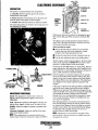
ELECTRONIC GOVERNOR
CONTRO.LLER
DESCRIPTION
GOVERNOR
PC BOARD
The system is composed if three basic components.
1. Controller. The PC board that governs the system is
located in the control panel.
~.J~-GIIiN (P3)
2.Se;""r. Mounted on the flywheel cover, the sensor measures the speed of the engine (via the ring gear).
CONTROL
PANEL
3. Actuator. Electronically controls the carburetor throttle.
-J;;j·I-IJ1I--STABILITY (P2)
(INTERIOR
The sensor and actuator are wired thru the wiring harness to
the controller (pC board).
SPEED (Pl)
VIEW)
ACTUATOR
FEEDBACK (P4)
""
Following are the basic procedures for adjusting the speed
(PI). stability (P2), gain (P3), and actuator feedback (P4)
pots.
The adjusting pots (except speed) have physical internal
stops. Tum to the right (clockwise) to increase, tum to the
left (counter-clockwise) to decrease.
Before starting the engine
• Remove all loads and tum off the AC circuit breaker
to insure that loads will not be subjected to voltage
variations while these adjustment are made.
• Decrease the speed pot to prevent overspeed at start up.
• Tum the other adjustment pots to the middle position.
Start the engine, monitor speed and adjust to the hertz rating
of the unit by adjusting the SPEED (PI) as needed. Verify
that the AC voltage output is in the correct range.
Decreasing the gain (P3) dampens no load hunting. With the
engine running at no load and proper speed, manually bump
the throttle lever to cause hunting. If necessary, decrease the
gain in small increments to eliminate hunting.
O.03OIn (O.762mm) After the engine's no load speed and gain are set correctly,
the AC circuit breaker can be turned on and the ships load
applied. In the event of speed variations with loads applied,
the stability (P2) pot may need adjustment. This adjustment
also chapges how the engine responds to generator load
MAGNmC PIr.I'_III'~""
(MPU) PN 046874
950 - 1000 OHM
changes.
SENSOR
If the range of adjustment of either gain (P3) or stability (Pl)
pots do ·not correct engine hunting, the actuator feedback
(P4) pot can be increased. This adjustment dampens the signals to the throttle control actuator. Increasing this adjustment
will decrease the amount of throttle control resolution.
Because of this, it is recommended the adjustment be made
in very small increments. The gain and stability pots may
now need to be readjusted.
FLYWHEEL
RING GEAR
ADJUSTMENT PROCEDURE
Speed. This adjustment is used to raise or lower the
engine's speed. This generator engine is set to run at
2200 RPM.
Most hunting problems occur because of mechanical problems with the linkage between the actuator and the carburetor. Insure that the linkage is free of any debris or corrosion
and that it moves freely. It is recommended that the linkage
be lubricated with a graphite lubricant. Do not use oil
because it tends to collect dirt and dust.
Gain. Adjusts the overall set of the engine. If too low, the
engine seems sluggish, to high causes the engine to hunt.
Stability. Adjusts the engine's response to generator load
changes.
Alternator Feedback. Adjusts the stability of the speed
signal to the throttle actuator.
NOTE: Adjustments to one parameter may affect others,
such as speed. It may be necessary to readjust some pots
throughout this process.
NOTE: These adjustments are extremely delicate and
require proper meters for measuring voltage and RPM'S.
~
WESTERBEKE
Engines & Generators
21
ENGINE ADJUSTMENTS
ADJUSTING THE DRIVE BELT
BELT ASSEMBLY VIEWED FROM BENEATH
The engine's drive belt is located under the engine. To
access the belt, for inspection and/or adjustment, remove
the cover as shown. Inspect the belt for wear along the edges
and for proper belt tension (belt should be tight).
The belt tension can be checked by meassuring the
spring length.
1 1/41n (31.79mm)
r-L,--,-l-_..JAM
To set the spring tension at 1-114", release the jam nut and
use a rod such as an allen wrench to tmn the adjustinf nut Cas
shown) to tighten or loosen the spring tension, which in tum
adjusts the tension on the belt.
. IT IS NORMAL FOR SOME BELT
OUST TO ACCUMULATE IN THE
ENGINE PAN, SIMPLY WIPE CLEAN
COVER
The lubricating system is a pressure feeding system using an
oil pump. The engine oil is drawn from the oil sump by the
oil pump, which drives the oil, under pressure, through the
oil filter and various lubricating parts in the engine. The oil
then returns to the oil sump to repeat the continuous cycle.
When the oil pressure exceeds the specified pressure, the oil
pushes open the relief valve in the oil pump and returns to
the oil sump, keeping the oil pressure within it's specified
range.
TESTING OIL PRESSURE
To test the oil pressure, remove the oil switch and install a
mechanical oil pressure gauge in it's place, it will be
necessary to connect the two switch wires together for the
engine to run. After wanning up the engine, with the engine
speed at 2200 rpm, read the oil pressure gauge.
OIL PRESSURE: belween 14 and 40 psi AT 2200 rpm
NOTE: A newly started (cold) engine, may have an oil
up to 40 psi. A warmed engine can have an oil
pressure as low as 14 psi. Oil pressure will vary depending
pres~ure
on the load placed on the generator.
OIL PRESSURE SWITCH/SENSOR
~T~aY~DRWMBaow
The generator is fitted with an oil pressure shutdown
switch. Should the engine's oil pressure drop below the safe
minimum, the switch will shut the engine down to prevent
damage by interrupting the DC voltage to the ignition coil.
NOTE: The specified minimum oil pressure is 5 psi. A gradual
loss of oil pressure usually indicates worn bearings. For
additional infonnation on low oil pressure readings, see the
ENGINE TROUBLESHOOTING Chait.
I'=-.::::tWESTERBEKE
Engines & Generators
22
ENGINE ADJUSTMENTS
ENGINE COMPRESSION TEST
WATER PUMP BELT
To check the engine's compression pressure, warm up the
engine, then shut it down.
To remove, replace or adjust the belt, loosen the pivot bolt
and release the adjusting bolt. Slide the water pump bracket
to slacken the belt for removal. When replacing and
adjusting the belt, set the belt very tight and tighten the bolt
and nut.
1. Remove both spark plug caps and both spark plugs.
2. Install a compression adapter and gauge in a spark
plug hole.
3. Close the thru hull valve (seacock).
The dual water pumps on the FRESH WATER COOLED
MODELS use the same drive belt and the adjustment is the
4. Crank the engine several times quickly so that the gauge
pointer reaches it's maximum.
same.
STANDARD CDMPRESStON PRESSURE AT 500 RPM:
71 PSt (5± 1 Kg/em') (D.4± 0.1 MPa)
5. Test the compression pressure on the other cylinder.
If either cylinder is below the standard try adding a
small amount of engine oil through the spark plug hole
and repeat the test.
(a) If additional oil causes an increase of pressure,
the piston ring andlor cylinder may be worn
or damaged.
(b) If additional oil does not increase compression
pressure suspect poor valve contact, valve seizure
or valve wear.
6. Reinstall the two plugs, connect the wires and open the·
thm hull valve (seacockl.
""'"'-,
WATER PUMP
RR4e"'r'
- - -----.. -
"m
NOTE: The adjusm,ent is the same for the FRESH WATER
COOLED MODEL dual pumps.
Engines & Generators
23
ENGINE ADJUSTMENTS
SPARK PLUGS
The spark plugs should be cleaned and re-gapped after the
first 50 hour break-in period, then inspected every 250 hours
thereafter and replaced as needed.
A WARNING: Do not remove the spark plugs while
the engine is hot. Allow the engine to cool before
removing them.
SPARK PLUG GAP: 0.032 - 0.035in. (0.8· 0.9mm).
SPARK PLUG TORQUE: 11-15Ib-H (15 - 26 Nm).
NOTE: Loctite Anti-Seize applied to the threaded portion of
the spark plugs will retard corrosion, making future removal
of the spark plugs easier.
t
GAP
INSPECT FOR
WEAR & CARBON
T-::J'
/ ' INSPECT FOR
/ ' DAMAGE
INSPECTING
THE SPARK
PLUGS
THERMOSTAT [Raw Water Cooled Models]
A thermostat controls the coolant temperature as the raw water
continuously flows through the closed cooling circuit. When
the engine is first started, the closed thermostat prevents the
water from flowing (some water is by-passed around the
thermostat to provide coolant circulation in the engine block).
As the engine warms up, the thennostat gradually opens. The
thermostat is accessible and can be checked, cleaned, or
replaced easily. Carry a spare thermostat and gasket.
If you suspect a faulty thermostat, place it in a pan of water
and bring to a boiL A working thermostat should open when
heated and close when cold.
------CHECK FOR
DETERIORATION
AND DAMAGE
CHOKE SOLENOID
The choke solenoid is a 12 volt DC operated unit that
is an integral part of the carburetor. When the engine is cold,
exira fuel is supplied to the engine. The choke is controlled
by the ignition control module and requires no adjustments.
ZINC ANODE [Raw Water Cooled Models]
The zinc anode is located just below the thermostat cover
and next to the oil fJiter. The purpose of the zinc anode is to
sacrifice itself to electrolysis aCtion taking place in the raw
water cooling circuit, thereby reducing the effects of
electrolysis on other components of the system. The
condition of the zinc anode should be checked monthly and
tile anode cleaned or replaced as required. Spare anodes
should be carried on board.
THERMOSTAT
ASSEMBLY
ZINC ANODE
THE GASKET IS SEALED TO
THE CASTING AND, UNLESS
DAMAGED, CAN BE LEFT IN
POSITION. ADO SEALANT TO
THE GASKET SURFACE WHEN
REASSEMBLING THE COVER.
NOTE: Refer to the Cooling System
pages for Fresh Water Cooled Thennostat
mui Zinc Allode assemblies.
Engines & Generators
24
ZINC ANODE
AND GASKET
ENGINE ADJUSTMENTS
VALVE CLEARANCE
It is routine maintenance to adjust the valve clearance after
the first fifty hours of operation. Valve clearance adjustment
must be performed when the engine is cool and the piston
must be the top dead center of the compression stroke.
Perform the following adjustment steps:
VALVE #1
EXHAUST
SlOE
INTAKE
SIDE
AOJUSTING
1. Remove the fuel pump and fuel filter from the cylinder
head cover. 1his assembly can be set aside without
disconnecting the hoses.
2. Remove the cylinder head cover..
FEELER GAUGE
#2
7. Adjust the intake and exhaust valve clearance for cylinder
#2 using the same sequence.
NOTE: When loosening and tigkJening the lock nut, hold
the adjusting screw with a valve clearance driver to pre
vent it from moving.
3. Remove the flywheel cover to access the flywheel and
. .
driven pulley.
VALVE
CLEARANCE
DRIVER
NOTE: The governor sensor (11Ulg pick-up) wires can be
disconnected at the sid of the control panel.
8. Install the cylinder head cover. Apply sealant to the inside
rim of the cover as indicated by the shaded area of the
drawing.
BOLT TORQUE:
8 -10 Nm (0.8 '1.0 kg·m) 5.8 - 7.2Ib-H
FLYWHEEL
9. Install the flywheel cover and re-attach the sensor wires.
5. Adjust the intake and exhaust valve clearance for
cylinder #!.
a. Loosen the lock put.
b. Insert a-feeler gauge between the valve end and the
adjusting screw.
Co Set the valve clearance by the adjusting screw.
VALVE CLEARANCE:
IN1lIKE: 0.13· O.17mm (0.035 - O.OD7in)
E EXHAUST: 0.18 -O.22mm (0.007 - O.DDgin)
SEAL THIS AREA
WITH LOCTITE
BLACK SILICONE
II. TIghten the lock nut
e. Again, check the valve clearance.
6. Thrn the driven gear and align the "2 and 0" mark on the
driven pulley with the " '17" mark on the cylincter head.
Engines & Generators
25
ENGINE ADJUSTMENTS
INSPECTIONJREPLACING OF THE TIMING BELT
o~·~D
If cracks, wear, lengthening or other damage is found,
replace the timing belt
LIMIT OF ELONGATION: MORE THAN 10mm (0.4 IN) DEFLECTION BY
PUSHING WITH YOUR ANGER
t
Replacement of the Timing Belt
1. Remove the parts in the following order:
a. Spark plugs
6. Recoil starter
c. Magneto flywheel cup
d. Altemator assembly
e. Alternator bracket
2. Tum the crankshaft and align "0" mark on the drive
pulley and the "0" mark on the cylinder head.
3. Remove the timing belt from the driven pulley side.
4. Install the timing belt from the drive pulley side.
FLYWHEEL CUP
NOTE: After installing the timing belt, when the aligning
"0" mark on the drive pulley with "0" on the cylinder
block. Please confirm that the "1 & 0" or ''2 & 0" mark
on the driven pulley are aligned with the "'V" mark on the
cylinder head
NOTE: Always keep the timing belt away from any oil and
grease.
'V MARK
AlTERNATOR BRACKET
TIMING BELT
~
WESTERBEKE
EngInes & Generators
25A
TROUBLESHOOTING GUIDE 3.0 KW BPMG
When toubleshooting indicates an electrical problem, see the
ELECTRICAL SYSTEM WIRING DIAGRAM, as this may
reveal other possible causes of the problem which are not listed
below.
PROBLEM
Engine does not
crank.
Engine starts, runs
and then shuts
down.
Engine starts, runs
but does nol come
up to speed.
Engine cranks but
falls to start
(Engine will crank
for 15 seconds)
Engine hunts.
PROBABLE CAUSE
1. Voltage drop at starter solenoid
terminal.
2. Main 10 amp fuse blown.
4. Battery is low or dead.
5. Loose battery connections.
6. Faulty wire connection.
7. Faulty start switch.
8 Faulty pc board
9. Faulty starter solenoid
10. Water filled cylinders.
1. Faulty shutdown switch,(oil pressure,
or exhaust temperature).
2. Faulty overspeed switch.
3. Dirty fueVwater separator filter.
4. Clogged fuelline.
5. Low oil level in sump.
6. Faulty fuel pump.
7. No fuel
8. Clogged fuel filter
1. Faulty mag-pickup sensor.
2. Electronic governor controller faulty,
3. Fuel pump.
4. Fuel supply to engine restricted.
5. Actuator linkage binding.
6. Actuator or electrical connections
faulty.
7. Air intake restricted.
8. Exhaust restricted.
1. Out olluel.
2. Engine is flooded.
3. Faulty carburetor. (See Carburetor page)
4. Faulty choke solenoid
5. Faulty ignition coil.
6. Bad spark plugs
1. Controller gain adjustment needed.
2. Faulty fuel pump.
3. Faulty PC board.
4. Improper drive belt tension.
5. Low DC battery voltage.
6. High exhaust back pressure.
7. Dirty fuel filter
8. Generator overload.
9. Valves need adjustment.
The following troubleshooting tables are based upon certain
engine problem indicators and the most likely causes of the
problems
PROBLEM
PROBABLE CAUSE
Engine misfires.
1. Poor quality fuel.
2. Faulty ignition control module.
3. Dirty flame arrester.
4. Faulty ignition wires.
5. Spark plugs are worn.
6. Binding actuator linkage.
7. High exhaust back-pressure.
8. Valve clearances are incorrect.
9. Valve clearances are incorrect.
Engine backfires.
1. Faulty ignition control module.
2. Incorrect timing.
3. Engine is flooded. See Engine is
flooded under Engine cranks but
fails to start.
4. Dirty flame arrester.
5. Faulty ignition coil.
6. High exhaust back-pressure.
Engine overheats.
1. Blockage in cooling water flow: inspect
the raw water intake, intake strainer,
pump impellers, and look for broken or
seperated hoses.
2. Belts may be loose or broken.
3. Obstructed by-pass hose.
Low oil pressure.
1. Low oil level.
2. Wrong SAE type oil in the engine.
3. Oil diluted with fuel.
4. Relief valve is stuck.
5. Faulty oil pump.
6. Faulty engine bearings.
7. Boat heeled over too much.
8. Faulty oil filter.
High oil pressure.
1. Dirty oil or wrong SAE type oil in the
engine.
2. Relief valve is stuck.
No DC charge to the
starting battery.
1. Faulty connections to
battery charging control.
2. 20 amp fuse blown/faulty.
3. Faulty voltage regulator.
4. Faulty magneto.
Engines & Generators
26
TROUBLESHOOTING GUIDE 3.0 KW BPMG
PROBABLE CAUSE
PROBLEM
Blue Exhausl Smoke Discharge
from the Engine
1. Lube oil is diluted.
2. High lube oil level.
3. Crankcase breather hose is clogged.
4. Valves are worn or adjusted incorrectly.
5. Piston rings are worn or unseated.
Black exhaust smoke Discharge
from the Engine
1.
2.
3.
4.
5.
6.
Poor performance
at generator speed
1. Contaminates in carburetor.
2. Faulty fuel pump/contaminated.
3. Electronic governor controller needs
adjustment.
Starter stays energized
after start
1. Faulty MPU suspected. Check MPU.
2. Faulty starter solenoid.
Unit starts and runs
at Idle speed
1. Check MPU signal. 1.5 - 2.0 VAC cranking.
2. Faulty overspeed board.
Dirty flame arrester.
Faulty carburetor.
Idle mixture jet too rich.
Accelerator diaphragm leaking.
Valves are worn or incorrectly adjusted.
Piston rings are worn or unseated.
Note: MPU voltages to PC board:
Cranking: 1.5 - 2.0 VAC
Running: 4.0 - 5.0 VAC
(2200 rpm)
.... WESTERBEKE
Engines & Generators
27
AC GENERATOR
MOTOR DATA
The power required to start an electric motor is considerably
more than is required to keep it running after it is started.
Some motors require much more current to start them than
others. Split-phase CAC) motors require more current to start,
under similar circumstances, than other types. They are commonly used on easy-starting loads, such as washing
machines, or where loads are applied after the motor is
started, such as small power tools. Because they require 5 to
7 times as much current to start as to run, their use should be
avoided, whenever possible, if the electric motor is to be driven by a small generator. Capacitor and repulsion-induction
motors require from 2 to 4 times as much current to start as
to run. The current required to start any motor varies with the
load connected to it. An electric' motor connected to an air
compressor, for example, will require more current than a
motor to which no load is connected.
In general, the current required to start 115-Volt motors connected
to medium starting loads will be approximately as follows:
MOTOR SIZE
(HP)
AMPS FOR
AMPS FOR
(rUNNIN~)
AMPERES
(~TARTING
1/6
1/4
1/3
1/2
3/4
1
PERMANENT MAGNET GENERATOR
Engine rpm at 2200
Generator tums at 3600 (60 Hz), 3000 (50Hz)
60Hz 120 volts125 amps, 50 Hz 230 voltsl13 amps
AMPERES)
6.41022.4'
9.21032.2'
10.410 72.S'
14.41029;2'
20.41040.S'
261052
3.2
4.6
5.2
7.2
10.2
13
"NOTE: In the above table the maximum Amps for Starting is
more for some small motors than for larger ones. The reason
for this is that the hardest starting types (split-phase) are not
made in larger sizes.
A
WARNING: Do not attempt to make adjustments or
repairs to the generator. the generator Is maintenance
free. If the generator fails (no ac output), contact your
WESTERBEKE dealer or distributor.
Because the heavy surge of current needed for starting
motors is required for ouly an instant, the generator will not
be dsmaged if it can bring the motor up to speed in a few
seconds. If difficulty is experienced in starting motors, tum
off all other electrical loads and, if possible, reduce the load
on the electric motor.
Required Operating Speed
Run the generator first with no load applied, then at half the
generators capacity, and finally loaded to its full capacity as
indicted on the generators data plate. The output voltage
should be checked periodically to ensure proper operation of
the generating plant and the appliances it supplies. To
mortitor voltage and load, check it with a portable meter and
ampprobe.
RED ISOLATION POST
0
WHITE
N
AC OUTPUT CONNECTIONS 120V 60Hz
Generator Maintenance
L1
Maintaining reasonable cleanliness is important. Connections
of tenninal boards and rectifiers may become corroded, and
insulation surfaces may start conducting if salts, dus~ engine
exhaus~ carbon, etc. are allowed to build up. Clogged ventilation opertings may cause excessive heating and reduced life
of·wimlings.
GREEN TO STARTER GROUND
AC
---)-----,
In addition to periodic cleaning, the generator should be
inspected for tightness of all connections, evidence of
overheated terminals and loose or damaged wires:
220V·50HZ
CONNECTIONS FOR
230V 50Hz
~
REO ISOLATION POST
WESTERBEKE
Engines & Generators
28
WHITE
Q
Q
Q
Q
N
LOAD
GREEN
GENERATOR WIRING DIAGRAM
RESISTANCE VALUES IN OHMS IN BLACK ITALIC
12.5· 18.511
~-EXCITER
1.4·2.1fl
MAG. COIL
tl6 6lK/RED
MAGNETIC
COIL
~ II G BLH IRED
~CI<U'
tl6 YEL/REO
t G 6LK
tiS OLK
tl6 OlK
)'
148,222[1
SH I [LOrD
IGNIT10N
PULSERCOIL
~
BOO[1
MAG. PICK·UP
~
116 REOI NT
116 ORG
MODULE
SPARK
PLUGS
IGNTION
COIL
116 ORG
tl6 REDI HT
116 8LU
DH
C-. 12.5 • tun
116 TEL
116 YEL/REO
U.2.1n.----....-\.../'"
MAG. COIL'
In
116
EXCITER COIL
tl6 8LK
OIL PRESS
IU YEl
C~ETOR
SOlENOID
FUSE
0.21· OAID
SWITCH
20n
CARB SOLENOID
116 REO
ALT. COIL
BATTERY
12 VDC
CO'-
,-~-+0
EXHAUST
_lUlE
RELAY
SWITCH
BATTERY
51\"1 rCH
.16
116 GRM/RED
18 OLK
ACTUATOR: 3.0 ~ 3.10
RESISTANCE VALUES IN OHMS
ACTUATOR
MAGNETO COIl. ....................1.4· 2.1
STARlER
o
.14 BLK
SOLENOID
EXCITER COiL ..................... 12.5 -18.8
f.7D
START SOLENOID
PULSER COIl.. ......................148 - 222
ENGINE CONNECTOR
ALTERNATOR COIl. ................. D.27 - 0.41
COIUROl PC BOARO
IGNITION COIl.. ••••••••••••••••••••• 0.26 - 0.35
(Pllmary)
MAGNETIC PICK·UP.................800
START SOLEN'DlD ................... 4.7
fUSE lOA
I
116 RED/WHT
+
I
PAHEL/RElioTE
COIIMECTOR
HIGH TENSION LEADS .............. 6.S00·fO.DOD
116 BlK
CARBERATOR SOLENOID •••••••••• 20
.
.,60RG
ACTUATOR ....................... " •• 3.D ·3.1
NOTE: TESTER USED· FLUKE MUL17METER
TOLERANCE ± 20%
HT
.", ,VEL
RENOT( SHUTDOWN TERNIMAL
I: POSITIVE (+)
2: AUX. SHUTDOWN
UNIT CAN
AESTART
UNIT CMf
NOT RESTAAT
•
dJ®ct
3: ENERG(NCY STOP
4: GROUND (-I
JUNPERIS) NUST BE RENOVEO
-@@@
TERMINALS 1 & 2 ARE FOR
."FIREBOY~ CONNECTION
OVERSPEEO PC BOARO (PN #045377)
r+.
116 GAN
I
I~Z
'-- -@ffi@
"
"
PANEL/RE),IOTE CONNECTOR
.TERMINAlS 3 & 4 ARE FOR
"EMERGENCY STOP SWlTCH"
CONTROL. P(;_ !IOARD
co
4
2 I
'~'
'.
I
A
Q-
'"
START/STOP
S'MTC~~,
BlK
PART NUMBERS: REMOTE STOP/START PANEL #048056 PANEL EXTENSION HARNESS 15FT #048200,30 FT #048201
GREEN TO STARTER GROUND
RED ISOLATION POST
REO ISOLATION POST
o
WHITE
AC
___
J------,
N
220V·50HZ
WHITE
o
CONNECTIONS FOR
230V 50Hz
L1
o
AC OUTPUT CONNECTIONS 120V 60Hz
-.,yo
WESTERBEKE
Engines & Generators
29
l
N
LOAD
GREEN
GENEIIAt
LAY-UP AND RECOMMISSIONING
INTAKE MANIFOLD
Many ow
includin ners rely on their boatyards to prepare their craft,
off-seas g engines and generators, for lay-up during the
accomp~n Or for long periods of inactivity. Others prefer to
Th
sh lay_up preparation themselves.
Clean the filter screen in the flame arrester, and place a clean
cloth lightly soaked in lube oil around the flame arrester to
block any opening. Also place an oil-soaked cloth in the
thru-hull exhaust port. Make note to remove cloths prior to
start-up!
ow~ 1~edures which follow will allow you to perform your
others d up and recommissioning, or to use as a check list if
0 the procedures.
Theseproc
during a I edures should afford your engine protection
mainten ay-up and also help familiarize you with the
Ify h anee needs of your engine.
au av
your lOcal. e any questions regarding lay-up procedures, call
provide
servicing dealer; he will be more than willing to
asSISlance .
FUEL SYSTEM
Top off your fuel tanks with unleaded gasoline of 89 octane
or higher. A fuel conditioner such as stabil gasoline stabilizer
should be added. Change the element in your gasoline/water
separator and clean the metal bow I. Re- install and make
certain there are no leaks. Clean up any spilled fuel.
STARTER MOTOR
ENGINE
If the en ~OOLING (Raw Water Cooled Models)
more th glne will be out of commission for 3 months or
fresh 'w e engine's cooling passages should be flushed with
and the ~ter. Also the water pump(s) should be disassembled
for ftu.s~Pellers stowed in a cool, dark area. Instructions
page.
g the cooling system are shown on the next
Lubrication and cleaning of the starter drive pinion is
advisable, the pinion is accessible when the flywheel cover is
removed. Make sure the battery connections are shut off
before attempting to remove the starter. Take care in properly
replacing any electrical connections removed from the starter.
SPARES
Lay-up time provides a good opportunity to inspect your
WESTERBEKE engine to see if external items such as drive
belts or coolant hoses need replacement. Check your basic
spares kit and order items not on hand, or replace those items
used during the lay-up, such as filters and zinc anodes. Refer
to the SPARE PARTS section of this manual.
LUBRICAtiON SYSTEM
With the
.
oil sum engine warm, drain all the lubricating oil from the
with ne~ ~move and replace the oil filter and fill the sump
ENGINe OIL Use the correct grade of oil. refer to the
oil chan _LUBRICATING OIL pages in this manual for the
are no 1~lng procedure. Run the engine and make sure there
r-_~&kS_
BATTERIES
----------------------------,
~i~4.UTION: Do not leave the engine's old
If batteries are to be left on board during the lay-up period,
make sure they are fully charged, and will remain that way,
to prevent them from freezing. If there exists any doubt that
the batteries will not remain fully charged, or that they will
be subjected to severe environmental conditions, remove
the batteries and store them in a warmer, more compatible
Lubr/i atl"g oil In the sump over the IaY·UP period.
PTOd::atl,.g oil and combustion deposits combine to
YOur ece harmful chemicals which can reduce the life of
environment.
"'91"e'5 internal parts.
~
WESTERBEKE
Engines & Generators
30
LAY-UP AND RECOMMISSIONING
RECOMMISSIONING
The recommissioning of your WESTERBEKE engine after a
seasonal lay-up generally follows the same procedures as
those presented in the PREPARATIONS FOR STARTING
section regarding preparation for starting and nonnal starts.
However, some of the lay-up procedures will need to be
counteracted before starting the engine.
1. Remove the any rags that were placed in the exhaust,
intake manifold, or flame arrester.
4. Check the condition of the zinc anode in the circuit and
clean or replace the anode as needed.
5. Check the condition of the heat exchanger zinc, clean or
replace as needed. (Fresh Water Cooled Models)
6. Make certain all electrical connections and switches are in
the correct position and there are no-loads on the generator at start up. (see GENERATOR)
7. Inspect the fresh water pump impeller, replace if necessary. (Fresh Water Cooled Models)
2. Reinstall the batteries that were removed during the
lay-up and reconnect the battery cables,. making ~ure the
terminals are clean and that the connectIOns are tIght.
Check to make sure the batteries are fully charged.
remove the spark plugs, wipe clean, re-gap, and install to
proper tightness.
3. Make certain the cooling system intake hose is attached
and the thru-hull valve is open .
8. Start the engine in accordance with the procedures
described in the PREPARATIONS FOR STARTING
section of this manual.
. FLUSHING THE ENGINES COOLING SYSTEM
RAW WATER COOLED MODELS
Engine flushing should be perfonned a minimum of at least
Run the unit for IO minutes or longer to adequately flush the
twice per operating season, more often in those areas where
cooling system.
the unit may not be subject to winter storage. In those
.
The fresh water will flush out the engine's water passages and
locations where the unit is used year round, f1ushmg the UUlt
exhaust lines. If the engine is being stored and there is a probonce every 4 months is recommended.
ability of freezing, flush the engine with fresh water and then
This procedure is best accomplished by disconnecting the
prior to shutting the unit doW!1. Substitute the fresh water
water intake hose from the vessel's thru-hull fittmg. Insert
supply with a concentrated antifreeze mixture and run this
the hose end into a large container of fresh water.
through the engine to provide freeze and corrosion protection
Close the thru-hull intake valve before disconnecting
for both the engine and exhaust system.
the hose.
When recommissioning, make certain the thru-hull intake
Before starting the engine, remove the engine thennostat
valve is open so the engine will quickly receive cooling
(replace the gasket and cover). This will ensure a full flow
water.
of water thru the engine. Re-install the thermostat once
nnshlng is complete.
NOTE: Prior to flushing the engine, inspect the coolant by·
CAUTION: Do not connect an external fresh water
pass hose and its attachruent fittings to insure that there are
supply directly to the engine's cooling system. This can
no obstructions occurring in the fittings or the hose.
cause flooding of the engine resulting in internal
Provide an external fresh water supply for the container to
rJ!!.;~~'@,,---------------~
maintain the water level in the container while the unit is being il'
operated during the flushing process.
"""U--o,,---
A
~:;;;;;>~A~I WJUER FILTER
RAW WATER
Engines & Generators
31
FRESH WATER
EXTERNAL FRESH
WATER SUPPLY
3.0 KW BPMG GENERATOR SPECIFICATIONS
ENGINE SPECIFICATIONS
COOLING SYSTEM
Engine Type
Two cylinder, four stroke gasoline engine.
General
Water cooled via raw water pump.
Bore & Stroke
2.32 x 2.36 inches (59 x 60 mm)
Raw Water Pump
Total Displacement
20.0t Cubic Inches {.33 liter)
Positive displacement type, rubber impeller,
belt driven.
Bearings
Two main bearings.
1.75 GPM (6.6 LPM) (before thermostat opens)
Valve System
Overhead cam-cross flow.
Raw Water Flow
(into water injected
exhaust elbow)
2.0 GPM (7.5 LPM) (thermostat open)
Compression Ratio
9:1
Operating Temperature
140°F (60°C)
Firing Order
1- 2
Aspiration
Naturally aspirated.
Direction of Rotation
Counterclockwise viewed from the back end.
Inclination
25° maximum angle of operation
Dry Weight
165 Ibs (75 Kg)
Governor
Electronic
AC GENERATOR (SINGLE PHASE)
Type
Permanent magnet (two pole)
Speed
3600 RPMl60Hz
3000RPMl50Hz
3.0Kw
3.0 KW - 60 Hz Single phase, 120 volts
2 wire, 25 amp
3.0 KW - 50 Hz single phase, 230 volts
2 wire, 13 amp
FUEL SYSTEM
Fuel Pump
Mechanical fuel pump.
Fuel
Unleaded 89 octane or higher gasoline.
Ignition Timing
BTDC 25° (not adjustable).
Spark Plug Gap
0.032 - 0.035in (O.8 - 0.9mm)
Ignition Coil
12 volt.
Spark Plug Torque
11-15Ib-ft{15-20Nm)
BoltTorque
See TORQUING THE CYLINDER HEAD.
Flame Arrester
Metal screen type.
Carburetor
Single barrel side draft.
Fuel Consumption
0.4 GPH@2200 RPMl25 Amps
TUNE-UP SPECIFICATIONS
AIR REQUIREMENTS
(Full Load)
Ignition Timing
12-Volt flywheel magneto.
Engine Combustion
13 CFM (O.287 cmm)
Generator Cooling
200 CFM (5.66 cmm)
ELECTRICAL SYSTEM
Start Motor
12-Volt reduction gear with solenoid.
Starting Battery
12-Volt, (-) negative ground
Battery Capacity
600-900 Cold Cranking Amps (CCA)
Battery Charging
11 Amp
DC Amperage Draw
70 Amps DC
FRESH WATER COOLED MODELS
LUBRICATION SYSTEM
Type
Wet sump system trochoid type pump.
Oil Filter
Fuel flow, paper element, spin-on disposals.
COOling System
Fresh water cooled block, thermostatically
controlled thru a heat exchanger.
Fresh Water (coolant)
Pump
Positive displacement, rubber impeller belt
driven
Raw Water Pump
Positive displacement, rubber impeller belt
driven
2.5 - 3.0 GPM
9.5 -11.3 LPM
Oil Capacity
1.5 qts. (91.4 L)
Raw Water Flow
(into water injected
exhaust elbow)
Oil Grade
API SJ 10W-30, 15W-40
Operating Temperature
~
WESTERBEKE
Engines & Generators
32
METRIC CONVERSIONS
INCHES TO MILLIMETERS
Inches
mm
1
2
3
4
5
10
25.40
50.80
76.20
101.60
127.00
254.00
15
20
25
30
35
40
MILLIMETERS TO INCHES
mm
mm
Inches
mm
Inches
381.00 .
508.00
635.00
762.00
889.00
1016.00
1
2
3
4
5
10
0.0394
0.0787
0.1181
0.1575
0.1969
0.3937
15
20
25
30
35
40
0.5906
0.7874
0.9843
1.1811
1.3780
1.5748
Inches
10 MILUMETERS =1 CENTIMETER, 100 CENTIMETERS =1 METER =39.37 INCHES (3.3 FEET)
INCHES TO METERS
Inches
Meters
1
2
3
4
5
6
0.0254
0.0508
0.0762
0.1016
0.1270
0.1524
Inches
METERS TO INCHES
Meters
7
8
9
10
11
12
Meters
0.ln8
0.2032
0.2286
0.2540
0.2794
0.3048
Inches
0.1
0.2
0.3
0.4
0.5
0.6
3.937
7.874
11.811
15.748
19.685
23.622
Meiers
Inches
0.7
0.8
0.9
1.0
1.1
1.2
27.559
31.496
35.433
39.370
43.307
47.244
'TO CONVERT METERS TO CENTIMETERS, MOVE DECIMAL POINT TWO PLACES TO THE RIGHT
YARDS TO METERS
METERS TO YARDS
Yards
Meters
Yards
Meters
Meters
Yards
Meters
1
2
3
4
5
0.91440
1.82880
2.74320
3.65760
4.57200
6
7
8
9
10
5.48640
6.40080
7.31520
8.22960
9.14400
1
2
3
4
5
1.09361
2.18723
3.28084
4.37445
5.46807
6
7
8
9
10
Yards
6.56168
7.65529
8.74891
9.84252
10.93614
MOVE DECIMAL POINT FOR HIGHER VALUES - e.g. 6,000 METERS = 6,561.68 YARDS
POUNDS TO KILOGRAMS
Ib
kg
1
2
3
4
5
0.454
0.907
1.361
1.814
2.288
Ib
6
7
8
9
10
KILOGRAMS TO POUNDS
kg
kg
Ib
kg
Ib
2.722
3.175
3.629
4.082
4.536
1
2
3
4
5
2.205
4.409
6.614
8.818
11.023
6
7
8
9
10
13.228
15.432
17.637
19.842
22.046
GALLONS TO LITERS
. Gallons
1
2
3
4
5
Liters
3.79
7.57
11.36
15.14
18.93
LITERS TO GALLONS
Gallons
Liters
Liters
Gallons
10
20
30
40
50
37.86
75.71
113.57
151.42
189.28
1
2
5
10
20
0.26
0.53
1.32
2.64
5.28
PINTS TO LITERS
Pints
Liters
0.47
0.95
1.42
1.89
2.37
1
2
3
4
5
Liters
Gallons
60
90
120
150
180
15.66
23.77
31.32
39.62
47.54
LITERS TO PINTS
Pints
Liters
6
7
8
9
10
2.84
3.31
3.79
4.26
4.73
Liters
1
2
3
4
5
Pints
Liters
2.11
4.23
6.34
8.45
10.57
6
7
8
9
10
Pints
12.68
14.79
16.91
19.02
21.13
TEMPERATURE
32
40
50
I
I
I
60
I
70
I
75
85
I
I
95
I
105
I
140
I
175 212
I
I
I
I
I
I
I
I
I
I
I
I
I
I
0
5
10
15
20
25
30
35
40
60
80
100
~
WESTERBEKE
Engln~s
& Generators
33
OF
°C
STANDARD AND METRIC CONVERSION DATA
LENGTH-DISTANCE
Inches (in) x 25.4 = Millimeters (mm) x .0394 = Inches
Feet (ft) x .305 = Meters (m) x 3.281 = Feet
Miles x 1.609 = Kilometers (km) x .0621 = Miles
DISTANCE EQUIVALENTS
1 Degree of Latitude = 60 Nm = 111.120 km
1 Minute of Latitude = 1 Nm = 1.852 km
VOLUME
Cubic Inches (in') x 16.387 = Cubic Centimeters x .061 =in'
Imperial Pints (IMP pt) x .568 = Liters (L) x 1.76 = IMP pt
Imperial Quarts (IMP qt) x 1.137 = Liters (L) x.88 = IMP qt
Imperial Gallons (IMP gal) x 4.546 = Liters (L) x .22 = IMP gal
Imperial Quarts (IMP qt) x 1.201 = US Quarts (US qt) x .833 = IMP qt
Imperial Gallons (IMP gal) x 1.201 = US Gallons (US gal) x .833 = IMP gal
Fluid Ounces x 29.573 = Milliliters x .034 = Ounces
US Pints (US pt) x .473 = Liters(L) x 2.113 = Pints
US Quarts (US qt) x .946 = Liters (L) x 1.057 = Quarts
US Gallons (US gal) x 3.785 = Liters (L) x .264 = Gallons
MASS-WEIGHT
Ounces (oz) x 28.35 = Grams (g) x .035 = Ounces
Pounds (I b) x .454 = Kilograms (kg) x 2.205 = Pounds
PRESSURE
Pounds Per Sq In (psi) x 6.895 = Kilopascals (kPa) x .145 = psi
Inches of Mercury (Hg) x .4912 = psi x 2.036 = Hg
Inches of Mercury (Hg) x 3.377 = Kilopascals (kPa) x .2961 = Hg
Inches of Water (H,O) x .07355 = Inches of Mercury x 13.783 = H,O
Inches of Water (H,O) x .03613 = psi x 27.684 = H,O
Inches of Water (H,O) x .248 = Kilopascals (kPa) x 4.026 = H,O
TORQUE
Pounds-Force Inches (in-Ib) x .113 = Newton Meters (Nm) x 8.85 =in-Ib
Pounds-Force Feet (ft-Ib) x 1.356 = Newton Meters (Nm) x .738 = ft-Ib
VELOCITY
Miles Per Hour (MPH) x 1.609 = Kilometers Per Hour (KPH) x .621 = MPH
POWER
Horsepower (Hp) x .745 = Kilowatts (Kw) x 1.34 = MPH
FUEL CONSUMPTION
Miles Per Hour IMP (MPG) x .354 = Kilometers Per Liter (Km/L)
Kilometers Per Liter (Km/L) x 2.352 = IMP MPG
Miles Per Gallons US (MPG) x .425 = Kilometers Per Liter (Km/L)
Kilometers Per Liter (Km/L) x 2.352 = US MPG
TEMPERATURE
Degree Fahrenheit (OF) = (OC X 1.8) + 32
Degree Celsius (OC) = (OF - 32) x .56
LIQUID WEIGHTS
Diesel Oil = 1 US gallon = 7.13 Ibs
Fresh Water = 1 US gallon = 8.33 Ibs
Gasoline = 1 US gallon = 6.1 Ibs
Salt Water = 1 US gallon = 8.56 Ibs
Engines & Generators
. 34-
SUGGESTED SPARE PARTS
WESTERBEKE MARINE GASOLINE GENERATORS
CONTACT YOUR WESTERBEKE DEALER FOR SUGGESTIONS AND ADDITIDNAL INFORMATION
FUEL FILTER
CARTRIDGE
AND O-RINGS
THERMOSTAT
AND GASKET
SPARI(PLUGS
~
GASOLINE
FUEl/WATER
FILTERS
--
lOA FUSE
ION S/DE OF
CONTROL PANEL)
~ ..: '.
&f
. '
FUSE~.
,
'. 20A IN-LINE
.
",
~
/!
:
. ENGINE BELT
WATER PUMP BELT
WATER PUMP
IMPEllERS, O-RINGS
AND GLYCERIN TUBE
WESTERBEKE ALSO RECOMMENDS
HAVING ENOUGH OIL ON-BOARD
FOR AT LEAST ONE OIL CHANGE
,"<;:'" .'
ZINC
ANODE
OIL FILTER
- - - - - - - - - SPARE PARTS K I T S - - - - - - - WESTERBEKE also offers two Spare Parts Kits,
each packaged in a rugged hinged toolbox.
Kit A includes the basic spares.
, Kit B is for more extensive off-shore cruising.
, KIT B
IMPELLER KIT
OIL FILTER
GENERATOR DRIVE BELT
ZINC ANODES WITH GASKET
, SPARK PLUGS
20A FUSE
WATER PUMP BELT
FUEL FILTER KIT
lOA FUSE
COMPLETE GASKET SET
THERMOSTAT KIT
WATER PUMP REPAIR KIT
OIL PRESSURE SWITCH
HEAT EXCHANGER ZINC
KIT A
IMPELLER KIT
OIL FILTER
GENERATOR DRIVE BELT
ZINC ANODES WITH GASKET
SPARK PLUGS
20A FUSE
WATER PUMP BELT
FUEL FILTER KIT
lOA FUSE
HEAT EXCHANGER ZINC
Engines & GeneraJors
35
.... WESTERBEKE
Engines & Generators
1071WMDW-4/0448009