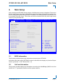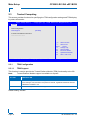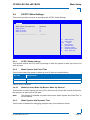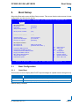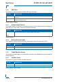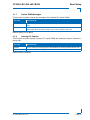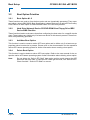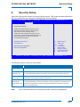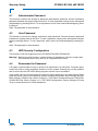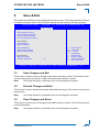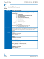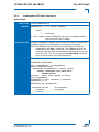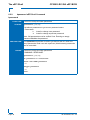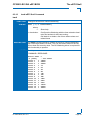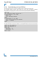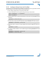
1
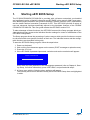
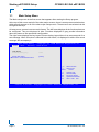
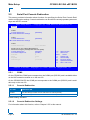
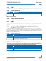
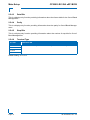
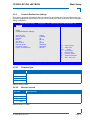
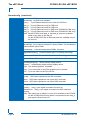
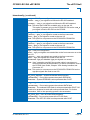
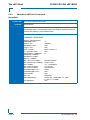
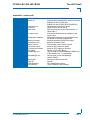
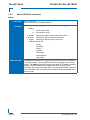
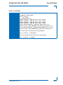
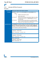
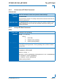
CP3002 / CP3002-RC / CP3002-RA uEFI BIOS Doc. ID: 1042-8946, Rev. 3.0 April 28, 2011 If it’s embedded, it’s Kontron. PRELIMINARY » User Guide « Preface CP3002/-RC/-RA Revision History Publication Title: CP3002/-RC/-RA uEFI BIOS User Guide Doc. ID: 1042-8946 PRELIMINARY Rev. Brief Description of Changes Date of Issue 1.0 Initial issue based on the uEFI BIOS version R10 8-Oct-2010 2.0 Added description for the CP3002 uEFI BIOS, update based on the uEFI BIOS version R13 8-Apr-2011 3.0 General update based on the uEFI BIOS version R13 28-Apr-2011 Imprint Kontron Modular Computers GmbH may be contacted via the following: MAILING ADDRESS TELEPHONE AND E-MAIL Kontron Modular Computers GmbH +49 (0) 800-SALESKONTRON Sudetenstraße 7 [email protected] D - 87600 Kaufbeuren Germany For further information about other Kontron products, please visit our Internet web site: www.kontron.com. Disclaimer Copyright © 2011 Kontron AG. All rights reserved. All data is for information purposes only and not guaranteed for legal purposes. Information has been carefully checked and is believed to be accurate; however, no responsibility is assumed for inaccuracies. Kontron and the Kontron logo and all other trademarks or registered trademarks are the property of their respective owners and are recognized. Specifications are subject to change without notice. Page ii ID 1042-8946, Rev. 3.0 CP3002/-RC/-RA uEFI BIOS Preface Table of Contents Revision History .........................................................................................................ii Imprint ........................................................................................................................ii Disclaimer ..................................................................................................................ii Table of Contents ...................................................................................................... iii 1. Starting uEFI BIOS Setup .............................................................3 1.1 Main Setup Menu ......................................................................................... 4 2. Main Setup .....................................................................................9 2.1 BIOS Information .......................................................................................... 9 2.2 UnCore Information ...................................................................................... 9 2.3 Trusted Computing ..................................................................................... 10 2.3.1 TPM Configuration ............................................................................. 10 2.3.1.1 TPM Support ............................................................................. 10 2.4 S5 RTC Wake Settings ...............................................................................11 2.4.1 S5 RTC Wake Settings .......................................................................11 2.4.2 Wake System with Fixed Time ...........................................................11 2.4.2.1 2.4.3 Wake-Up Hour, Wake-Up Minute, Wake-Up Second .................11 Wake System with Dynamic Time ......................................................11 2.5 Serial Port Console Redirection ................................................................. 12 2.5.1 COM0 ................................................................................................ 12 2.5.1.1 Console Redirection .................................................................. 12 2.5.1.2 Console Redirection Settings .................................................... 12 2.5.2 COM1 ................................................................................................ 13 2.5.2.1 Console Redirection .................................................................. 13 2.5.2.2 Console Redirection Settings .................................................... 13 2.5.3 COM4 ................................................................................................ 13 2.5.4 Serial Port for Out-of-Band Management/Windows EMS ................. 13 2.5.4.1 Console Redirection .................................................................. 13 2.5.4.2 Out-of-Band Mgmt Port ............................................................. 13 2.5.4.3 Data Bits .................................................................................... 14 ID 1042-8946, Rev. 3.0 Page iii PRELIMINARY 1.2 Navigation .................................................................................................... 5 Preface 2.5.4.4 Parity ..........................................................................................14 2.5.4.5 Stop Bits .....................................................................................14 2.5.4.6 Terminal Type ............................................................................14 2.5.5 PRELIMINARY CP3002/-RC/-RA uEFI BIOS Console Redirection Settings .............................................................15 2.5.5.1 Terminal Type ............................................................................15 2.5.5.2 Bits per second ..........................................................................15 2.5.5.3 Data Bits ....................................................................................16 2.5.5.4 Parity ..........................................................................................16 2.5.5.5 Stop Bits .....................................................................................16 2.5.5.6 Flow Control ...............................................................................16 2.5.5.7 Recorder Mode ..........................................................................16 2.5.5.8 Resolution 100x31 .....................................................................17 2.5.5.9 Legacy OS Redirection ..............................................................17 2.6 System Language .......................................................................................17 2.7 System Date ...............................................................................................17 2.8 System Time ...............................................................................................17 2.9 Access Level ...............................................................................................18 3. Boot Setup .................................................................................. 21 3.1 Boot Configuration ......................................................................................21 3.1.1 Quiet Boot ..........................................................................................21 3.1.2 uEFI Boot ...........................................................................................22 3.1.3 Setup Prompt Timeout .......................................................................22 3.1.4 Bootup NumLock State ......................................................................22 3.1.5 CSM16 Module Version .....................................................................22 3.1.6 GateA20 Active ..................................................................................22 3.1.7 Option ROM Messages ......................................................................23 3.1.8 Interrupt 19 Capture ...........................................................................23 3.2 Boot Option Priorities ..................................................................................24 3.2.1 Boot Option #1..2 ...............................................................................24 3.2.2 Hard Drive/Network Device/CD/DVD ROM Drive/Floppy Drive/ etc..24 3.2.3 Add New Boot Option .........................................................................24 3.2.4 Delete Boot Option .............................................................................24 Page iv ID 1042-8946, Rev. 3.0 CP3002/-RC/-RA uEFI BIOS 4. Preface Security Setup .............................................................................27 4.1 Administrator Password ............................................................................. 28 4.2 User Password ........................................................................................... 28 4.3 HDD Security Configuration ....................................................................... 28 4.4 Remember the Password ........................................................................... 28 5. Save & Exit ...................................................................................31 5.1 Save Changes and Exit .............................................................................. 31 5.3 Save Changes and Reset .......................................................................... 31 5.4 Discard Changes and Reset ...................................................................... 32 5.5 Save Changes (Save Options) ................................................................... 32 5.6 Discard Changes (Save Options) ............................................................... 32 5.7 Restore Defaults (Save Options) ................................................................ 32 5.8 Save as User Defaults (Save Options) ....................................................... 32 5.9 Restore User Defaults (Save Options) ....................................................... 32 5.10 Boot Override ............................................................................................. 32 6. The uEFI Shell ..............................................................................35 6.1 Introduction, Basic Operation ..................................................................... 35 6.1.1 Shell Startup ...................................................................................... 35 6.2 Kontron Shell Commands .......................................................................... 36 6.2.1 kboardconfig uEFI Shell Command ................................................... 37 6.2.2 kboardinfo uEFI Shell Command ....................................................... 40 6.2.3 kboot uEFI Shell Command ............................................................... 42 6.2.4 kbootnsh uEFI Shell Command ......................................................... 44 6.2.5 kclearnvram uEFI Shell Command .................................................... 45 6.2.6 kclsp uEFI Shell Command ............................................................... 45 6.2.7 kflash uEFI Shell Command .............................................................. 46 6.2.8 kmkramdisk uEFI Shell Command .................................................... 47 6.2.9 kpassword uEFI Shell Command ...................................................... 48 6.2.10 kwdt uEFI Shell Command ................................................................ 49 6.3 uEFI Shell Scripting .................................................................................... 51 ID 1042-8946, Rev. 3.0 Page v PRELIMINARY 5.2 Discard Changes and Exit .......................................................................... 31 PRELIMINARY Preface 7. CP3002/-RC/-RA uEFI BIOS 6.3.1 Startup Scripting .................................................................................51 6.3.2 Create a Startup Script .......................................................................51 6.3.3 Examples of Startup Scripts ...............................................................51 6.3.3.1 Automatic Booting from USB Flash Drive ..................................51 6.3.3.2 Switch On Clock Spreading Prior to Booting from Harddrive ....51 6.3.3.3 Execute Shell Script on Other Harddrive ...................................51 6.3.3.4 Enable Watchdog and Control PXE Boot ..................................52 6.3.3.5 Handling the Startup Script in the Flash Bank ...........................53 Updating the uEFI BIOS ............................................................. 57 7.1 BIOS Redundancy Strategy ........................................................................57 7.2 Updating Strategy .......................................................................................57 7.3 uEFI BIOS Recovery ..................................................................................57 7.4 Determining the Active Flash ......................................................................57 Page vi ID 1042-8946, Rev. 3.0 Starting uEFI BIOS Setup Chapter 1 Starting uEFI BIOS Setup ID 1042-8946, Rev. 3.0 Page 1 PRELIMINARY CP3002/-RC/-RA uEFI BIOS PRELIMINARY Starting uEFI BIOS Setup CP3002/-RC/-RA uEFI BIOS This page has been intentionally left blank. Page 2 ID 1042-8946, Rev. 3.0 CP3002/-RC/-RA uEFI BIOS 1. Starting uEFI BIOS Setup Starting uEFI BIOS Setup The CP3002/CP3002-RC/CP3002-RA is provided with a Kontron-customized, pre-installed and configured version of Aptio® (referred to as uEFI BIOS in this manual), AMI’s next generation BIOS firmware based on the Unified Extensible Firmware Interface (uEFI) specification and the Intel® Platform Innovation Framework for EFI. This uEFI BIOS provides a variety of new and enhanced functions specifically tailored to the hardware features of the CP3002/ CP3002-RC/CP3002-RA. This user guide reflects the uEFI BIOS version R13. To take advantage of these functions, the uEFI BIOS comes with a Setup program which provides quick and easy access to the individual function settings for control or modification of the uEFI BIOS configuration. To start the uEFI BIOS Setup program, follow the steps below: 1. 2. 3. 4. Power on the board. Wait until the first characters appear on the screen (POST messages or splash screen). Press the <F2> key. If the uEFI BIOS is password-protected, a window such as the one below will appear: Enter Password Enter either the User password or the Administrator password (refer to Chapter 4, Security Setup, for further information), press <RETURN>, and proceed with step 2. 5. A Setup menu with the following token attributes will appear. The currently active menu and the currently active uEFI BIOS Setup item are highlighted in white. ID 1042-8946, Rev. 3.0 Page 3 PRELIMINARY The Setup program allows the accessing of various menus which provide functions or access to sub-menus with more specific functions of their own. The individual menus and the configurable functions are described in this guide. Starting uEFI BIOS Setup 1.1 CP3002/-RC/-RA uEFI BIOS Main Setup Menu The Main setup menu is the first screen that appears after starting the Setup program. At the top of this screen and all of the other major screens, there is a setup menu selection bar, which permits access to all of the other major setup menus. These menus are selected via the left-right arrow keys. All setup menu screens have two main frames. The left frame displays all the functions that can be configured. They are displayed in blue. Functions displayed in gray provide information about the status or the operational configuration. The right frame displays the key legend. Above the key legend there is an area reserved for a text message. When a function is selected in the left frame, it is displayed in white. Often a text message will accompany it. PRELIMINARY Aptio Setup Utility - Copyright (C) 2009 American Megatrends, Inc. Ma in Bo ot Security S a ve & E x i t Title (black) Read only field (grey) value Setup item (blue) [value] Pointer to a subordinate menu : Select Screen : Select Item Enter: +/-: F1: F2: F3 F4: Select Change Opt. General Help Previous Values Optimized Defaults Save ESC: Exit Ve r s i o n 2 . 0 0 . 1 2 0 1 . C o p y r i g h t ( C ) 2 0 0 9 A m e r i c a n M e g a t r e n d s , I n c . Page 4 ID 1042-8946, Rev. 3.0 CP3002/-RC/-RA uEFI BIOS 1.2 Starting uEFI BIOS Setup Navigation The CP3002/CP3002-RC/CP3002-RA uEFI BIOS setup program uses a hot key-based navigation system. A hot key legend is located in the right frame on most setup screens.The following table provides information concerning the usage of these hot keys. HOT KEY DESCRIPTION <F1> The <F1> key is used to invoke the General Help window. <F2> The <F2> key is used to restore the previous values. <F3> The <F3> key is used to load the defaults. <F4> The <F4> key is used to save the current settings and exit the uEFI BIOS Setup. Left/Right The Left and Right <Arrow> keys are used to select a major Setup screen. For example: Main Screen, Advanced Screen, Chipset Screen, etc. Up/Down The Up and Down <Arrow> keys are used to select a Setup function or a sub-screen. + - Plus/Minus The Plus and Minus <Arrow> keys are used to change the field value of a particular Setup function, for example, system date and time. <ESC> The <ESC> key is used to exit a menu or the uEFI BIOS Setup. Pressing the <ESC> key in a sub-menu causes the next higher menu level to be displayed. When the <ESC> key is pressed in a major Setup menu, the uEFI BIOS Setup is terminated without saving any changes made. <Enter> The <Enter> key is used to execute a command or select a menu. ID 1042-8946, Rev. 3.0 Page 5 PRELIMINARY PRELIMINARY Starting uEFI BIOS Setup CP3002/-RC/-RA uEFI BIOS This page has been intentionally left blank. Page 6 ID 1042-8946, Rev. 3.0 Main Setup Chapter 21 Main Setup ID 1042-8946, Rev. 3.0 Page 7 PRELIMINARY CP3002/-RC/-RA uEFI BIOS PRELIMINARY Main Setup CP3002/-RC/-RA uEFI BIOS This page has been intentionally left blank. Page 8 ID 1042-8946, Rev. 3.0 CP3002/-RC/-RA uEFI BIOS 2. Main Setup Main Setup Upon entering the uEFI BIOS Setup program, the Main setup screen is displayed. This screen lists the main setup sub-screens and provides very basic system information as well as functions for setting the system time and date. In addition, the remaining major setup menus can be accessed from this screen. This screen can also be selected from any other major setup screen by using the Main tab. Aptio Setup Utility - Copyright (C) 2009 American Megatrends, Inc. Boot S e c u r it y S a v e & E x it BIOS Information BIOS Vendor Core Version Project Version Build Date American Megatrends 4.6.3.5 B3201 13.00 x64 02/18/2011 13:35:52 UnCore Information IGD VBIOS Version GMCH Version Total Memory 1930 18 [C2 Stepping] 4096 MB (DDR3: 1067 MHz) Memory Slot0 Memory Slot2 2048 MB (DDR3) 2048 MB (DDR3) Trusted Computing S5 RTC Wake Settings Serial Port Console Redirection : Select Screen : Select Item System Language [English] System Date System Time [Thu 03/24/2011] [11:47:30] Access Level Administrator Enter: +/-: F1: F2: F3 F4: Select Change Opt. General Help Previous Values Optimized Defaults Save ESC: Exit Ve r s i o n 2 . 0 0 . 1 2 0 1 . C o p y r i g h t ( C ) 2 0 0 9 A m e r i c a n M e g a t r e n d s , I n c . 2.1 BIOS Information This function provides display-only information concerning the uEFI BIOS. Information about the running uEFI BIOS version is reflected in the display-only function Project Version (parameter “13.00” indicates Rev. 13). 2.2 UnCore Information This function provides display-only information concerning the NorthBridge (GMCH die of the Intel® Core™ i7 processor) features and the system memory. ID 1042-8946, Rev. 3.0 Page 9 PRELIMINARY Main Main Setup 2.3 CP3002/-RC/-RA uEFI BIOS Trusted Computing This screen provides functions for specifying the TPM configuration settings and TPM displaying status information. Aptio Setup Utility - Copyright (C) 2009 American Megatrends, Inc. Ma in Bo ot Security TPM Configuration TPM Support S a ve & E x i t [Disable] PRELIMINARY Current TPM Status Information TPM SUPPORT OFF : Select Screen : Select Item Enter: +/-: F1: F2: F3 F4: Select Change Opt. General Help Previous Values Optimized Defaults Save ESC: Exit Ve r s i o n 2 . 0 0 . 1 2 0 1 . C o p y r i g h t ( C ) 2 0 0 9 A m e r i c a n M e g a t r e n d s , I n c . 2.3.1 TPM Configuration 2.3.1.1 TPM Support This function is used to provide the Trusted Platform Module (TPM) functionality to the OS. Note: Trusted Platform Module support is available on request. SETTING DESCRIPTION Disable Use this setting to disable the TPM support. If this setting is used, the TPM is not present for the OS, regardless whether the function TPM State is enabled or not. Enable Use this setting to enable the TPM support. Default setting: Disable Page 10 ID 1042-8946, Rev. 3.0 CP3002/-RC/-RA uEFI BIOS 2.4 Main Setup S5 RTC Wake Settings This screen provides functions for specifying the S5 RTC Wake Settings. Wake Wake Wake Wake Aptio Setup Utility - Copyright (C) 2009 American Megatrends, Inc. Boot S e c u r it y S a v e & E x it system with Fixed Time up hour up minute up second Wake system with Dynamic Time [Enabled] 0 0 0 [Disabled] : Select Screen : Select Item Enter: +/-: F1: F2: F3 F4: Select Change Opt. General Help Previous Values Optimized Defaults Save ESC: Exit Ve r s i o n 2 . 0 0 . 1 2 0 1 . C o p y r i g h t ( C ) 2 0 0 9 A m e r i c a n M e g a t r e n d s , I n c . 2.4.1 S5 RTC Wake Settings This function defines the RTC wake-up settings to allow the system to wake up from the S5 (soft off) state. 2.4.2 Wake System with Fixed Time This function allows the system to wake up from S5 state at a specified time. SETTING DESCRIPTION Disabled Use this setting to disable Wake System with Fixed Time. Enabled Use this setting to enable Wake System with Fixed Time. Default setting: Disabled 2.4.2.1 Wake-Up Hour, Wake-Up Minute, Wake-Up Second This function is used to specify the hour (0-23), the minute (0-59) and the second (0-59) when the system is to wake up from S5 state. Note: This function is available only when the function “Wake System with Fixed Time” is set to Enabled. 2.4.3 Wake System with Dynamic Time This function is intended for debugging purposes only and is therefore locked. ID 1042-8946, Rev. 3.0 Page 11 PRELIMINARY Main Main Setup 2.5 CP3002/-RC/-RA uEFI BIOS Serial Port Console Redirection This screen provides information about functions for specifying the Serial Port Console Redirection configuration settings. Console redirection can be used to remotely operate system settings and the EFI console. Aptio Setup Utility - Copyright (C) 2009 American Megatrends, Inc. PRELIMINARY Ma in Bo ot Security S a ve & E x i t COM0 Console Redirection Console Redirection Settings [Disabled] COM1 Console Redirection Console Redirection Settings [Disabled] COM4 Console Redirection Port Is Disabled Serial Port for Out-of-Band Management/ Windows Emergency Management Services (EMS) Console Redirection [Disabled] Out-of-Band Mgmt Port [COM0] Data Bits 8 Parity None Stop Bits 1 Terminal Type [VT-UTF8] : Select Screen : Select Item Enter: +/-: F1: F2: F3 F4: Select Change Opt. General Help Previous Values Optimized Defaults Save ESC: Exit Ve r s i o n 2 . 0 0 . 1 2 0 1 . C o p y r i g h t ( C ) 2 0 0 9 A m e r i c a n M e g a t r e n d s , I n c . 2.5.1 COM0 On the CP3002 the COM0 port corresponds to the COMA port (RS-232) and is available either on the 8HP extension module or on the rear I/O. On the CP3002-RA/-RC the COM0 port corresponds to the COMA port (RS-232) and is available only on the rear I/O. 2.5.1.1 Console Redirection SETTING DESCRIPTION Disabled Use this setting to disable console redirection for COM A (RS-232). Enabled Use this setting to enable console redirection for COM A (RS-232). Default setting: Disabled 2.5.1.2 Console Redirection Settings For information about this function, refer to Chapter 2.5.5 in this manual. Page 12 ID 1042-8946, Rev. 3.0 CP3002/-RC/-RA uEFI BIOS 2.5.2 Main Setup COM1 The COM1 port corresponds to the COMB port (RS-422/RS-232) and is available on the rear I/O. 2.5.2.1 Console Redirection SETTING DESCRIPTION Disabled Use this setting to disable console redirection for COM B (RS-422/RS-232). Enabled Use this setting to enable console redirection for COM B (RS-422/RS-232). Default setting: Disabled 2.5.2.2 Console Redirection Settings 2.5.3 COM4 On the CP3002/CP3002-RC/CP3002-RA, the COM4 port is not available and is therefore disabled. 2.5.4 Serial Port for Out-of-Band Management/Windows Emergency Management Services (EMS) The following functions control the presence and content of the ACPI serial port redirection table (SPCR). This table is mainly used by the Windows server variants to provide Windows Emergency Management Services (EMS). This functionality is totally independent from serial redirection of other console output. 2.5.4.1 Console Redirection SETTING DESCRIPTION Disabled Use this setting to prevent the system from adding the SPCR table to the ACPI tables. Enabled Use this setting to add the SPCR table to the ACPI tables. The OS can further use the information provided for serial redirection services. Default setting: Disabled 2.5.4.2 Out-of-Band Mgmt Port This function is used to select the serial port intended for use with Out-of-Band Management. This functionality is independent from serial redirection of other console output. SETTING DESCRIPTION COM0 Use this setting to specify that the serial port 0 is to be used with Out-of-Band Management. COM4 Use this setting to specify that a PCIe serial port is to be used with Out-of-Band Management. Default setting: COM0 ID 1042-8946, Rev. 3.0 Page 13 PRELIMINARY For information about this function, refer to Chapter 2.5.5 in this manual. Main Setup 2.5.4.3 CP3002/-RC/-RA uEFI BIOS Data Bits This is a display-only function providing information about the frame width for the Out-of-Band Management. 2.5.4.4 Parity This is a display-only function providing information about the parity for Out-of-Band Management. 2.5.4.5 Stop Bits This is a display-only function providing information about the number of stop bits for Out-ofBand Management. PRELIMINARY 2.5.4.6 Terminal Type SETTING DESCRIPTION VT100 Use one of these settings to select the terminal type for out-of-band management. VT100+ VT-UTF8 ANSI Default setting: VT-UTF8 Page 14 ID 1042-8946, Rev. 3.0 CP3002/-RC/-RA uEFI BIOS 2.5.5 Main Setup Console Redirection Settings This screen provides information about functions for specifying the Console Redirection configuration settings for the serial port 0 and a PCIe serial port. Each serial port can be independently configured. Aptio Setup Utility - Copyright (C) 2009 American Megatrends, Inc. Main Boot S e c u r it y S a v e & E x it Terminal Type Bits per second Data Bits Parity Stop Bits Flow Control Recorder Mode Resolution 100x31 Legacy OS Redirection [ANSI] [115200] [8] [None] [1] [None] [Disabled] [Disabled] [80x24] : Select Screen : Select Item Enter: +/-: F1: F2: F3 F4: Select Change Opt. General Help Previous Values Optimized Defaults Save ESC: Exit Ve r s i o n 2 . 0 0 . 1 2 0 1 . C o p y r i g h t ( C ) 2 0 0 9 A m e r i c a n M e g a t r e n d s , I n c . 2.5.5.1 Terminal Type SETTING DESCRIPTION VT100 Use one of these settings to select the terminal type to be emulated. VT100+ VT-UTF8 ANSI Default setting: ANSI 2.5.5.2 Bits per second SETTING DESCRIPTION 9600 Use one of these settings to select the baud rate of the serial port. 19200 57600 115200 Default setting: 115200 ID 1042-8946, Rev. 3.0 Page 15 PRELIMINARY COM0 Console Redirection Settings Main Setup 2.5.5.3 CP3002/-RC/-RA uEFI BIOS Data Bits SETTING DESCRIPTION 7 Use one of these settings to specify the number of data bits per frame. 8 Default setting: 8 2.5.5.4 Parity SETTING DESCRIPTION None Use one of these settings to select the parity for the serial port. PRELIMINARY Even Odd Mark Space Default setting: None 2.5.5.5 Stop Bits SETTING DESCRIPTION 1 Use one of these settings to specify the number of stop bits for the serial port. 2 Default setting: 1 2.5.5.6 Flow Control SETTING DESCRIPTION None Use one of these settings to specify the type of flow control to be used for this serial port. Hardware RTS/CTS Default setting: None 2.5.5.7 Recorder Mode SETTING DESCRIPTION Disabled Use this setting the disable Recorder Mode. Enabled Use this setting enable Recorder Mode. When this setting is used, all control escape sequences are suppressed from the serial redirection output. This may lead to a misformatted screen output but makes automatic storage of the serial console output easier. Default setting: Disabled Page 16 ID 1042-8946, Rev. 3.0 CP3002/-RC/-RA uEFI BIOS 2.5.5.8 Main Setup Resolution 100x31 SETTING DESCRIPTION Disabled Use this setting the disable extended terminal resolution. Enabled Use this setting the enable extended terminal resolution. Default setting: Disabled Legacy OS Redirection SETTING DESCRIPTION 80x24 Use one of these settings to select the number of rows and columns for legacy OSredirection. 80x25 Default setting: 80x24 2.6 System Language SETTING DESCRIPTION English Use this function to select the system language. Currently, only English is supported. 2.7 System Date SETTING DESCRIPTION <WD MM/DD/YYYY> Use this function to change the system date. Select System Date using the Up and Down <Arrow> keys. Enter the new values through the keyboard or press +/- to increment/decrement values. Use “Tab” to switch between date elements. 2.8 System Time SETTING DESCRIPTION <HH:MM:SS> Use this function to change the system time. Select System Time using the Up and Down <Arrow> keys. Enter the new values through the keyboard or press +/- to increment/decrement values. Use “Tab” to switch between time elements. Note: The time is in 24-hour format. For example, 5:30 A.M. appears as 05:30:00, and 5:30 P.M. as 17:30:00. ID 1042-8946, Rev. 3.0 Page 17 PRELIMINARY 2.5.5.9 Main Setup 2.9 CP3002/-RC/-RA uEFI BIOS Access Level This function provides display-only information concerning the uEFI BIOS Setup accessibility for the current Setup session. Depending on the type of password protection used, one of the following settings is displayed: SETTING DESCRIPTION Administrator This setting indicates that read/write access to all setup options is available. User This setting indicates that only a limited subset of all setup options is modifiable. If no password is set, the access setup is Administrator. PRELIMINARY Note: Page 18 ID 1042-8946, Rev. 3.0 Boot Setup Chapter 31 Boot Setup ID 1042-8946, Rev. 3.0 Page 19 PRELIMINARY CP3002/-RC/-RA uEFI BIOS PRELIMINARY Boot Setup CP3002/-RC/-RA uEFI BIOS This page has been intentionally left blank. Page 20 ID 1042-8946, Rev. 3.0 CP3002/-RC/-RA uEFI BIOS 3. Boot Setup Boot Setup Select the Boot tab to enter the Boot Setup screen. This screen lists the sub-screens for boot configuration and boot device priority. Aptio Setup Utility - Copyright (C) 2009 American Megatrends, Inc. Boot S e c u r it y S a v e & E x it Boot Configuration Quiet Boot UEFI Boot Setup Prompt Timeout [Disabled] [Enabled] 2 Bootup NumLock State [On] CSM16 Module Version 07.60 GateA20 Active Option ROM Messages Interrupt 19 Capture [Upon Request] [Force BIOS] [Disabled] Boot Option Priorities Boot Option #1 Boot Option #2 [Built-in EFI Shell] [SanDisk uSSD 5000 ...] Hard Drive BBS Priorities Network Device BBS Priorities CD/DVD ROM Drive BBS Priorities Floppy Drive BBS Priorities BEV Device BBS Priorities Add New Boot Option Delete Boot Option : Select Screen : Select Item Enter: +/-: F1: F2: F3 F4: Select Change Opt. General Help Previous Values Optimized Defaults Save ESC: Exit Ve r s i o n 2 . 0 0 . 1 2 0 1 . C o p y r i g h t ( C ) 2 0 0 9 A m e r i c a n M e g a t r e n d s , I n c . 3.1 Boot Configuration 3.1.1 Quiet Boot This function is used to display either POST output messages or a splash screen during boot-up. SETTING DESCRIPTION Disabled Use this setting to display POST output messages during boot-up. Enabled Use this setting to display a splash screen during boot-up. Default setting: Disabled ID 1042-8946, Rev. 3.0 Page 21 PRELIMINARY Main Boot Setup 3.1.2 CP3002/-RC/-RA uEFI BIOS uEFI Boot This function is used to enable or disable uEFI boot from disks. SETTING DESCRIPTION Disabled Use this setting to prevent the system from booting native uEFI-aware operating systems from disks. Enabled Use this setting to enable booting of native uEFI-aware operating systems from disks, if present, and in boot order. Default setting: Enabled PRELIMINARY 3.1.3 Setup Prompt Timeout This integer function is used to set an additional time the POST should wait for the operator to press the key to enter setup. The time is entered in seconds. SETTING DESCRIPTION 1 Use one of these settings to specify the setup prompt timeout. .. . 65535 Default setting: 2 3.1.4 Bootup NumLock State This function is used to set the state of the keyboard’s numlock function after POST. SETTING DESCRIPTION On Use this setting to switch on the keyboard’s numlock function after POST. Off Use this setting to switch off the keyboard’s numlock function after POST. Default setting: On 3.1.5 CSM16 Module Version This function provides display-only information concerning the CSM Module and is intended for internal use only. 3.1.6 GateA20 Active This function is used to enable or disable GateA20. SETTING DESCRIPTION Upon Request Use this setting to disable GateA20 in the uEFI BIOS. Always Use this setting to prevent the system from disabling GateA20. Default setting: Upon Request Page 22 ID 1042-8946, Rev. 3.0 CP3002/-RC/-RA uEFI BIOS 3.1.7 Boot Setup Option ROM Messages This function is used to control the messages of the loaded PCI option ROMs. SETTING DESCRIPTION Force BIOS Use this setting to force to a BIOS-compatible output. This will show the option ROM messages. Keep Current Use this setting to keep the current video mode. This will suppress option ROM messages. Option ROMs requiring interactive inputs may not work properly in this mode. Default setting: Force BIOS Interrupt 19 Capture This function is used to specify if legacy PCI option ROMs are allowed to capture software interrupt 19h. SETTING DESCRIPTION Disabled Use this setting to prevent legacy PCI option ROMs from capturing software interrupt 19h. Enabled Use this setting to allow legacy PCI option ROMs to capture software interrupt 19h. Default setting: Disabled ID 1042-8946, Rev. 3.0 Page 23 PRELIMINARY 3.1.8 Boot Setup 3.2 Boot Option Priorities 3.2.1 Boot Option #1..2 CP3002/-RC/-RA uEFI BIOS These functions are used to form the boot order and are dynamically generated. They represent either a legacy BBS (BIOS Boot Specification) class of devices or a native EFI boot entry. Press Return on each option to select the BBS class / EFI boot entry desired. 3.2.2 Hard Drive/Network Device/CD/DVD ROM Drive/Floppy Drive/ BEV Device BBS Priorities PRELIMINARY These functions lead to sub-menus that allow configuring the boot order for a specific device class. These options are visible only if at least one device for this class is present. These functions are dynamically generated. 3.2.3 Add New Boot Option This function is used to create a native uEFI boot option and is visible only if at least one appropriate native boot device is present. Please refer to the documentation for the respective native uEFI-aware operating system for further information about creating a boot option. 3.2.4 Delete Boot Option This function is used to delete a native uEFI boot option. Refer to the user manual for the respective native uEFI-aware operating system further information about deleting a boot option. Note: Page 24 Do not delete the “Built-in EFI Shell” boot option as this would remove the uEFI Shell from the boot order. In case the uEFI Shell got removed, use “Save & Exit” / “Boot Override” / “Built-in EFI Shell” to recover. ID 1042-8946, Rev. 3.0 Security Setup Chapter 41 Security Setup ID 1042-8946, Rev. 3.0 Page 25 PRELIMINARY CP3002/-RC/-RA uEFI BIOS PRELIMINARY Security Setup CP3002/-RC/-RA uEFI BIOS This page has been intentionally left blank. Page 26 ID 1042-8946, Rev. 3.0 CP3002/-RC/-RA uEFI BIOS 4. Security Setup Security Setup Select the Security tab to enter the Security Setup screen. This screen provides information about the passwords and functions for specifying the security settings. Aptio Setup Utility - Copyright (C) 2009 American Megatrends, Inc. Main Boot S e c u r it y S a v e & E x it If ONLY the Administrator’s password is set, then this only limits access to Setup and is only asked for when entering Setup. If ONLY the User’s password is set, then this is a power on password and must be entered to boot or enter Setup. In Setup the User will have Administrator rights. Administrator Password User Password HDD Security Configuration HDD 0:ST9120822SB : Select Screen : Select Item Enter: +/-: F1: F2: F3 F4: Select Change Opt. General Help Previous Values Optimized Defaults Save ESC: Exit Ve r s i o n 2 . 0 0 . 1 2 0 1 . C o p y r i g h t ( C ) 2 0 0 9 A m e r i c a n M e g a t r e n d s , I n c . The following modes of security are provided: SETTING DESCRIPTION No password is set Booting the system as well as entering the Setup is unsecured. Only Administrator password is set Booting the system is unsecured. Only User password is set The password is required for booting the system as well as for entering the Setup menu. On every startup, the user will be asked for the password. Both User and Administrator passwords are set Booting the system is unsecured. Note: If no valid Administrator password is entered, only limited access to Setup is provided. For entering the Setup, a password is required. If the User password is entered here, limited access to the Setup is granted. Entering the Administrator password provides full access to all Setup entries. The CP3002/CP3002-RC/CP3002-RA provides no factory-set passwords. ID 1042-8946, Rev. 3.0 Page 27 PRELIMINARY Password Description Security Setup 4.1 CP3002/-RC/-RA uEFI BIOS Administrator Password This function is used to set, change or delete the Administrator password. If there is already a password installed, the system asks for this first. To clear a password, simply enter nothing and acknowledge by pressing Return. To set a password, enter it twice and acknowledge by pressing Return. Note: The password is case-sensitive. 4.2 User Password PRELIMINARY This function is used to set, change or delete the User password. If there is already a password installed, the system asks for this first. To clear a password, simply enter nothing and acknowledge by pressing Return. To set a password, enter it twice and acknowledge by pressing Return. Note: The password is case-sensitive. 4.3 HDD Security Configuration This function is not fully supported on the CP3002/CP3002-RC/CP3002-RA. Warning! Before using this function, contact Kontron for assistance. Failure to comply with the instruction above may result in an irreparable disk lockout. 4.4 Remember the Password It is highly recommended to keep a record of all passwords in a safe place. Forgotten passwords may lead to being completely locked out of the system. Booting may not be possible, and in worst case the uEFI BIOS Setup program will also not be accessible. If the system cannot be booted because neither the User password nor the Administrator password are known, refer to the respective section providing information about clearing the uEFI BIOS settings (CP3002 User Guide, Chapter 4.1, DIP Switch Configuration and CP3002-RC/ CP3002-RA User Guide, Chapter 4.1.2, uEFI BIOS Configuration Jumper Settings (JP3 and JP4) or contact Kontron for further assistance. Page 28 ID 1042-8946, Rev. 3.0 Save & Exit Chapter 51 Save & Exit ID 1042-8946, Rev. 3.0 Page 29 PRELIMINARY CP3002/-RC/-RA uEFI BIOS PRELIMINARY Save & Exit CP3002/-RC/-RA uEFI BIOS This page has been intentionally left blank. Page 30 ID 1042-8946, Rev. 3.0 CP3002/-RC/-RA uEFI BIOS 5. Save & Exit Save & Exit Select the Save & Exit tab to enter the Save & Exit menu screen. This screen provides functions for handling changes made to the uEFI BIOS settings and the exiting of the Setup program. Aptio Setup Utility - Copyright (C) 2009 American Megatrends, Inc. Main Boot S e c u r it y S a v e & E x it Save Options Save Changes Discard Changes : Select Screen : Select Item Restore Defaults Save as User Defaults Restore User Defaults Boot Override Built-in EFI Shell SanDisk uSSD 5000 0.1 Enter: +/-: F1: F2: F3 F4: Select Change Opt. General Help Previous Values Optimized Defaults Save ESC: Exit Ve r s i o n 2 . 0 0 . 1 2 0 1 . C o p y r i g h t ( C ) 2 0 0 9 A m e r i c a n M e g a t r e n d s , I n c . 5.1 Save Changes and Exit This function is used to save all changes made within the Setup to flash. This function continues the boot process as long as no option was altered that requires a reboot. Note: The Setup will ask for confirmation prior to executing this command. 5.2 Discard Changes and Exit This function is used to discard all changes made within the Setup. This function continues the boot process. Note: The Setup will ask for confirmation prior to executing this command. 5.3 Save Changes and Reset This function is used to save all changes made within the Setup to flash. This function performs a reboot afterwards. Note: The Setup will ask for confirmation prior to executing this command. ID 1042-8946, Rev. 3.0 Page 31 PRELIMINARY Save Changes and Exit Discard Changes and Exit Save Changes and Reset Discard Changes and Reset Save & Exit 5.4 CP3002/-RC/-RA uEFI BIOS Discard Changes and Reset This function is used to discard all changes made within the Setup. This function performs a reboot afterwards. Note: The Setup will ask for confirmation prior to executing this command. 5.5 Save Changes (Save Options) PRELIMINARY This function is used to save all changes made within the Setup to flash. This function returns to Setup. Note: The Setup will ask for confirmation prior to executing this command. 5.6 Discard Changes (Save Options) This function is used to discard all changes made within the Setup. This function returns to Setup. Note: The Setup will ask for confirmation prior to executing this command. 5.7 Restore Defaults (Save Options) This function is used to restore all tokens to factory default. Note: The Setup will ask for confirmation prior to executing this command. 5.8 Save as User Defaults (Save Options) This function is used to save all current settings as user default. The current setup state can later be restored using Restore User Defaults. Note: The Setup will ask for confirmation prior to executing this command. 5.9 Restore User Defaults (Save Options) This function is used to restore all tokens to settings previously stored by Save as User Defaults. Note: The Setup will ask for confirmation prior to executing this command. 5.10 Boot Override This group of functions includes a list of tokens, each of them corresponding to one device within the boot order. Select a drive to immediately boot that device regardless of the current boot order. If booting to EFI Shell this way, an exit from the shell returns to Setup. Page 32 ID 1042-8946, Rev. 3.0 The uEFI Shell Chapter 61 The uEFI Shell ID 1042-8946, Rev. 3.0 Page 33 PRELIMINARY CP3002/-RC/-RA uEFI BIOS PRELIMINARY The uEFI Shell CP3002/-RC/-RA uEFI BIOS This page has been intentionally left blank. Page 34 ID 1042-8946, Rev. 3.0 CP3002/-RC/-RA uEFI BIOS 6. The uEFI Shell The uEFI Shell The Kontron uEFI BIOS features a built-in and enhanced version of the uEFI Shell. For a detailed description of the available standard shell scripting refer to the EFI Shell User’s Guide. For a detailed description of the available standard shell commands, refer to the Shell Command Manual 1.0. Both documents can be downloaded from the EFI and Framework Open Source Community homepage (https://efi-shell.tianocore.org) under the “Documents and Files” section. Please note that not all shell commands described in the Shell Command Manual 1.0 are provided by the Kontron uEFI BIOS. Introduction, Basic Operation The uEFI Shell forms an entry into the uEFI boot order and is the first boot option by default. It is simply started by putting the uEFI Shell first in boot and running the board as usual. 6.1.1 Shell Startup If the shell is executed, it displays its signon message followed by a list of detected devices. The output produced by the device mapping table can vary depending on the board’s configuration. EFI Shell version 2.00 [4.631] Current running mode 1.1.2 Device mapping table fs0 :Removable HardDisk - Alias hd33b0b0b blk0 Acpi(PNP0A03,0)/Pci(1D|7)/Usb(1, 0)/Usb(1, 0)/HD(Part1,Sig17731773) fs1 :Removable BlockDevice - Alias f33b0c0 blk1 Acpi(PNP0A03,0)/Pci(1D|7)/Usb(1, 0)/Usb(2, 0) blk0 :Removable HardDisk - Alias hd33b0b0b fs0 Acpi(PNP0A03,0)/Pci(1D|7)/Usb(1, 0)/Usb(1, 0)/HD(Part1,Sig17731773) blk1 :Removable BlockDevice - Alias f33b0c0 fs1 Acpi(PNP0A03,0)/Pci(1D|7)/Usb(1, 0)/Usb(2, 0) blk2 :HardDisk - Alias (null) Acpi(PNP0A03,0)/Pci(1F|2)/Ata(Primary,Master)/HD(Part1,SigC811D18D) blk3 :BlockDevice - Alias (null) Acpi(PNP0A03,0)/Pci(1F|2)/Ata(Primary,Master) blk4 :Removable BlockDevice - Alias (null) Acpi(PNP0A03,0)/Pci(1D|7)/Usb(1, 0)/Usb(1, 0) Press the ESC key within 5 seconds to skip startup.nsh, and any other key to continue. If the ESC key is pressed before the 5-second timeout has elapsed, the shell prompt is shown: Shell> ID 1042-8946, Rev. 3.0 Page 35 PRELIMINARY 6.1 The uEFI Shell 6.2 CP3002/-RC/-RA uEFI BIOS Kontron Shell Commands The Kontron uEFI implementation provides the following additional commands related to the specific HW features of the Kontron system: PRELIMINARY • • • • • • • • • • kboardconfig kboardinfo kboot kbootnsh kclearnvram kclsp kflash kmkramdisk kpassword kwdt The following tables provide information concerning these Kontron-specific commands. Where “RESPONSE” information is provided in “USAGE”, the value indicated in brackets is the currently selected setting. Where “SETTINGS” information is provided, the value indicated in brackets is the default setting. The uEFI Shell commands are case-sensitive. Page 36 ID 1042-8946, Rev. 3.0 CP3002/-RC/-RA uEFI BIOS 6.2.1 The uEFI Shell kboardconfig uEFI Shell Command kboardconfig FUNCTION: SYNTAX: Configure non-volatile board settings kboardconfig kboardconfig [-?|<device>|<setting>] DESCRIPTION: USAGE: Show online help Specify device from list Select configuration type The kboardconfig command is used to configure non-volatile board settings. Show all possible configurations COMMAND / RESPONSE: Shell> kboardconfig Control nonvolatile board settings Example: kboardconfig pxe: Select PXE boot network adapter ([disabled] all eth_a eth_b eth_c eth_d) StorageOrom: Launch Storage PCI OpROM (disabled [enabled]) HyperThreading: Enable Hyper Threading technology (disabled [enabled]) CpuTurbo: Enable CPU turbo mode technology (disabled [enabled] CpuC: Enable C states when the CPU is not 100% utilized (disabled [enabled]) PrimaryDisplay: Select primary display device ([auto] igd peg pci) SataMode: Determines how SATA controller(s) operate ([ide] ahci raid) com_a: Com A port configuration ([rear] extension) com_b: Com B port configuration (rs232 [rs422]) gbe_a: GbE A port configuration ([front] rear) gbe_b: GbE B port configuration ([front] rear) vga: VGA port configuration (auto [front] rear disabled) wr_prot_eeprom: System EEprom write protection ([disabled] enabled) wr_prot_sata: Onboard Sata flash write protection ([disabled] enabled) wr_prot_spi: EFI spi flash write protection ([disabled] enabled) Note: not all options are available on all variants. Show allowed settings e.g. for “PrimaryDisplay”: Shell> kboardconfig PrimaryDisplay PrimaryDisplay: Select primary display device PrimaryDisplay == auto Allowed options: auto, igd, peg, pci ID 1042-8946, Rev. 3.0 Page 37 PRELIMINARY where: ? <device> <setting> The uEFI Shell CP3002/-RC/-RA uEFI BIOS kboardconfig (continued) PRELIMINARY SETTINGS: pxe: Select PXE boot network adapter disabled: No PXE boot available [all]: Try all Ethernet devices round robin for PXE boot eth_a: Try only Ethernet port A for PXE boot eth_b: Try only Ethernet port B for PXE boot eth_c: Try only Ethernet port C for PXE boot (CP3002-RC/-RA only) eth_d: Try only Ethernet port D for PXE boot (CP3002-RC/-RA only) Note: On the CP3002, both eth_a and eth_b ports are available either on the front or the rear I/O. On the CP3002-RC/-RA, all Ethernet ports are available only on the rear I/O. StorageOrom: Launch Storage PCI Option ROMs disabled: Do not launch storage PCI option ROMs. This includes the onboard RAID option ROM. [enabled]: Launch storage option ROMs, if present HyperThreading: Enable/Disable Hyper-Threading Technology CpuTurbo: Enable/Disable CPU Turbo Boost Technology CpuC: Enable/Disable C states when the CPU is not 100% utilized PrimaryDisplay: Select primary display device [auto]: Automatically detect primary display device igd: Use internal graphics, if enabled peg: Try to use video on the PCIe graphics port, if present pci: Try to use video on the PCI bus first SataMode: Determines how SATA controllers operate [ide]: SATA ports operate as two IDE controllers ahci: SATA ports operate as one 6-port AHCI controller raid: SATA ports operate as one 6-port RAID controller com_a: COM A port configuration [rear]: com_a port signal is routed to the rear I/O extension: com_a port signal is routed to the 8HP extension module Note: This option has no effect if no rear I/O is attached to the CP3002. On the CP3002-RA/-RC this option is not present as the com_a port signal is fixed to rear I/O. Page 38 ID 1042-8946, Rev. 3.0 CP3002/-RC/-RA uEFI BIOS The uEFI Shell kboardconfig (continued) com_b: COM B port configuration rs232: com_b port signal level follows the RS-232 standard [rs422]: com_b port signal level follows the RS-422 standard Note: The serial port COM B is available only on the rear I/O. This option is present only on the CP3002-RC/-RA as the com_b port signal is fixed to RS-232 on the CP3002. gbe_b: GbE B port configuration [front]: gbe_b port signal is routed to the front connector rear: gbe_b port signal is routed to the rear I/O Note: This option is not present on the CP3002-RC/CP3002-RA. vga: VGA port configuration auto: vga port signals are routed either to the front connector or to the rear I/O [front]: vga port signals are routed to the front connector rear: vga port signals are routed to the rear I/O disabled: vga port disabled (vga port signals not routed) Note: “Auto” operation may fail if the monitor cable in use does not correctly follow the VESA standard. For further information, refer to the CP3002 User Guide, Chapter “VGA Analog Interface and Connector J6”. Note: This option is not present on the CP3002-RC/CP3002-RA as the vga port signals are fixed to rear I/O. wr_prot_eeprom: System EEPROM write protection [disabled]: Do not write protect the system EEPROM enabled: System EEPROM is write-protected after POST wr_prot_sata: Onboard SATA flash write protection [disabled]: Do not write protect the onboard SATA flash enabled: The onboard SATA flash is write-protected after POST. OS needs to be prepared to work with write-protected flash. For further information, refer to the operating system’s documentation. wr_prot_spi: uEFI SPI flash write protection [disabled]: Do not write protect the uEFI SPI flash enabled: The uEFI SPI flash is write-protected after POST ID 1042-8946, Rev. 3.0 Page 39 PRELIMINARY gbe_a: GbE A port configuration [front]: gbe_a port signal is routed to the front connector rear: gbe_a port signal is routed to the rear I/O Note: This option is not present on the CP3002-RC/CP3002-RA. The uEFI Shell 6.2.2 CP3002/-RC/-RA uEFI BIOS kboardinfo uEFI Shell Command kboardinfo FUNCTION: SYNTAX: DESCRIPTION: USAGE: Show board identification data kboardinfo The kboardinfo command shows a summary of board-specific identification data. It is especially useful for support queries because it contains this data in a concentrated form. Show board identification data COMMAND / RESPONSE: PRELIMINARY Shell> kboardinfo KOMaOEMF rev.: Board ID: Hardware rev.: Logic rev.: Boot flash: In system slot: Geographic address: Material number: Hardware index: Serial number: EFI article name: EFI material number: EFI index: EFI build time: EFI build date: NorthBridge rev.: SouthBridge rev.: Microcode: CPU ID: CPU Branding: RIO Module: Page 40 3 0xB320 0x0 0x1 Boot flash 0 Yes 8 SK-EFI-B3201 1039-2704 13, standard 13:35:52 02/18/2011 0x18 0x6 0x2 0x20655 Intel(R) Core(TM) i7 CPU L 620 @ 2.0GHz 001 ID 1042-8946, Rev. 3.0 CP3002/-RC/-RA uEFI BIOS The uEFI Shell USAGE: KOMaOEMF rev.: Board ID: Hardware rev.: Logic rev.: Boot flash: In system slot: Geographic Address: Material number: Hardware index: Serial number: EFI article name: EFI material number: EFI index: NorthBridge rev.: SouthBridge rev.: Microcode: CPU ID: CPU Branding: RIO Module: ID 1042-8946, Rev. 3.0 Revision of KOMaOEMF protocol Kontron board identification value (should be 0xB320 for the CP3002 and 0xB330 for the CP3002-RC/CP3002-RA) Hardware revision of this board Logic revision of this board Current boot flash: either “Boot flash 0” or “Boot flash 1” Indicates that the board is installed in the system slot Geographic address of the backplane slot the board is currently plugged into Kontron hardware reference number Kontron hardware index This board’s unique serial number Kontron uEFI reference name Kontron uEFI reference number Version of this uEFI BIOS Chip revision of the NorthBridge (GMCH die of the Intel® Core™ i7 processor) Chip revision of the SouthBridge (Intel ® QM57) Currently loaded microcode CPUID CPU identification string Type of attached RIO module Page 41 PRELIMINARY kboardinfo (continued) The uEFI Shell 6.2.3 CP3002/-RC/-RA uEFI BIOS kboot uEFI Shell Command kboot FUNCTION: PRELIMINARY SYNTAX: Boot a legacy OS Not to be used for uEFI BootLoaders! kboot [-?|-d|-p|-p <path>|-n <name>|-t <type>] where: ? Show online help -d Boot default order -p <path> Specify the path to the device to boot from -n <name> Specify the device name to boot from -t <type> Specify the device type to boot from Available types are: floppy harddrive cdrom network usb-floppy usb-harddrive usb-cdrom DESCRIPTION: Page 42 The kboot command boots a legacy OS. Boot device can be selected in a very flexible way. If the requested device is not present, boot returns to shell. The kboot command cannot boot native uEFI-aware operating systems. But since these are bootable from shell by calling their bootloader, this is not necessary either. If a requested device is present but not bootable, uEFI continues to boot with the next bootable device in the boot order. ID 1042-8946, Rev. 3.0 CP3002/-RC/-RA uEFI BIOS The uEFI Shell kboot (continued) USAGE: Show all connected devices: COMMAND / RESPONSE: PRELIMINARY fs0:\> kboot ____BBS_TABLE____ 00002 network “IBA GE Slot 0100 v1300” 00003 network “IBA GE Slot 0101 v1300” 00004 network “IBA GE Slot 0200 v1300” 00005 network “IBA GE Slot 0201 v1300” 00002 usb-harddrive “SanDisk uSSD 5000 0.1” Device path: Acpi(PNP0A03,0)/Pci(1A|7)/Usb(1,0) 0001 usb-harddrive “KingstonDataTraveler 2.04.10” Device path: Acpi(PNP0A03,0)/Pci(1D|7)/Usb(1,0) Boot from device containing the string “Kingston”: fs0:\> kboot -n Kingston Boot from the first device found that is of type floppy: fs0:\> kboot -t floppy ID 1042-8946, Rev. 3.0 Page 43 The uEFI Shell 6.2.4 CP3002/-RC/-RA uEFI BIOS kbootnsh uEFI Shell Command kbootnsh FUNCTION: SYNTAX: Manage the startup script stored in the flash kbootnsh [-b][-?|-g <filename>|-p <filename>|-d] where: PRELIMINARY -b -? -g <filename> -p <filename> -d DESCRIPTION: USAGE: Display output page by page Show online help Store the current boot script to disk. If there is no physical disk drive present, the kmkramdisk command may be used. Store the shell script pointed to by filename to flash. Note: The shell script cannot be larger then 400 bytes. Delete the current startup script from flash. The kbootnsh command manages the flash stored startup script. If the shell is launched by the boot process, it executes a shell script stored in the flash. If the shell script terminates, the shell executes a kboot -d command to continue the boot process. However, the shell script can of course contain any other boot command. Get current startup script to file named boot.nsh COMMAND / RESPONSE: Shell> kbootnsh -g boot.nsh Store file named boot.nsh to flash: COMMAND / RESPONSE: Shell> kbootnsh -p boot.nsh Delete startup script: COMMAND / RESPONSE: Shell> kbootnsh -d Page 44 ID 1042-8946, Rev. 3.0 CP3002/-RC/-RA uEFI BIOS 6.2.5 The uEFI Shell kclearnvram uEFI Shell Command kclearnvram FUNCTION: SYNTAX: Clear the NVRAM to restore the system’s default settings kclearnvram No parameters required. For safety reasons this command must be confirmed by pressing “c”. 6.2.6 The kclearnvram command allows to clear the system NVRAM. Since all EFI settings are stored inside the NVRAM, the default settings are loaded afterwards. kclsp uEFI Shell Command kclsp FUNCTION: SYNTAX: Configure clock spreading kclsp [-?|-d|-e] where: -? -d -e DESCRIPTION: USAGE: show help disable clock spreading enable clock spreading The kclsp command enables or disables clock spreading on the onboard core clock generator. Clock spreading can be used to reduce system EMI. Get help: COMMAND / RESPONSE: Shell> kclsp -? Kontron Clock Spreading Configuration for ICS9LPRS365 -d disable clock spreading -e enable clock spreading Default setting: disable ID 1042-8946, Rev. 3.0 Page 45 PRELIMINARY DESCRIPTION: The uEFI Shell 6.2.7 CP3002/-RC/-RA uEFI BIOS kflash uEFI Shell Command kflash FUNCTION: PRELIMINARY SYNTAX: Manage uEFI BIOS update kflash [-p|-i|-v|-s|-c|-h|-?] [-f] [-r] [file] Operation mode: -p Program flash -i Show information string and check CRC -v Verify flashed image -s Save current ROM image to file -c Clone flash content to second flash -h Show this help -? Show online help file uEFI BIOS binary file Options: -f Force write Expert options: Not recommended for standard use -r Raw image mode (.bin, .rom) DESCRIPTION: USAGE: The kflash command is used to program and verify the flash banks holding the uEFI BIOS code. uEFI BIOS binary files must be available from connected mass storage devices, such as USB flash drive or harddisk. Get help: COMMAND / RESPONSE: Shell> kflash -? Get help: COMMAND / RESPONSE: Shell> kflash -h Program uEFI BIOS into primary flash bank: COMMAND / RESPONSE: Shell> kflash -p BIOS_file.kfl Copy uEFI BIOS into secondary flash bank: COMMAND / RESPONSE: Shell> kflash -c Page 46 ID 1042-8946, Rev. 3.0 CP3002/-RC/-RA uEFI BIOS 6.2.8 The uEFI Shell kmkramdisk uEFI Shell Command kmkramdisk FUNCTION: SYNTAX: Create RAMdisk drives kmkramdisk [-?|-s <size> <name>] where: -? show help -s <size> <name> create a RAMdisk of given size in Megabytes with the mount point name <name> Creates a RAMdisk of variable size. Can be very useful to perform file operations when no real filesystem is connected to the system. Note: The RAMdisk loses its mount point name after all drives are remapped by the map -r command. The RAMdisk will then be enumerated as any other connected drive and gain a mount point name like “fs0”. This is not a bug of the kmkramdisk command but a normal function of the uEFI framework. USAGE: Create RAMdisk: COMMAND / RESPONSE: rd:\> kmkramdisk -s 5 myramdisk Device mapping table myramdisk :BlockDevice - Alias (null) VenMsg’(93B5F448-127A-4B29-B3065BE8AAC4826E) Success - Force file system to mount rd:\> myramdisk: myramdisk:\> echo testfile > testfile myramdisk:\> ls Directory of: myramdisk:\ 05/24/08 04:39a 1 File(s) 0 Dir(s) ID 1042-8946, Rev. 3.0 22 testfile 22 bytes Page 47 PRELIMINARY DESCRIPTION: The uEFI Shell 6.2.9 CP3002/-RC/-RA uEFI BIOS kpassword uEFI Shell Command kpassword FUNCTION: SYNTAX: Control EFI setup and shell passwords kpassword [-u|-s] Call without parameters to get current password status Parameters: -u -s Install or change user password Install or change superuser password PRELIMINARY Note: Old passwords must be verified if set. Entering an empty password disables the password. DESCRIPTION: USAGE: The kpassword command is used to get and set the EFI shell and setup passwords. Both user and superuser (Administrator) passwords can be controlled. Control EFI setup and shell passwords COMMAND / RESPONSE: kpassword [-u|-s] No password is installed! Enter new USER password --> Retype password --> Done. Page 48 ID 1042-8946, Rev. 3.0 CP3002/-RC/-RA uEFI BIOS 6.2.10 The uEFI Shell kwdt uEFI Shell Command kwdt FUNCTION: SYNTAX: Configure the Kontron onboard Watchdog kwdt [-?|-t <timeindex>] where: -? -t <timeindex> Show help Configure the Watchdog with the time related to timeindex and activate it with reset routing DESCRIPTION: USAGE: The kwdt command allows to enable the Kontron onboard Watchdog with reset target before OS boot. This can be used to detect if the OS fails to boot and react by reset. The OS Watchdog driver is required for this functionality to operate. Get help: COMMAND / RESPONSE: Shell> kwdt -t [time] value 0 = value 1 = value 2 = value 3 = value 4 = value 5 = value 6 = value 7 = value 8 = value 9 = value 10 = value 11 = value 12 = value 13 = value 14 = value 15 = ID 1042-8946, Rev. 3.0 -? - set Timer 125ms 250ms 500ms 1s 2s 4s 8s 16s 32s 64s 128s 256s 512s 1024s 2048s 4096s Page 49 PRELIMINARY Call kwdt -h to obtain a list of time index values and related times The uEFI Shell CP3002/-RC/-RA uEFI BIOS kwdt (continued) USAGE: Set Watchdog to 16 seconds and activate it COMMAND / RESPONSE (none): Shell> kwdt -t 7 Note: Because there is no application which triggers the Watchdog, the system will be reset after 16 seconds in this case. This command should be invoked from a script, followed by an operating system boot, and the OS then has to start triggering the Watchdog. Display Watchdog configuration: PRELIMINARY COMMAND / RESPONSE: Shell> kwdt Kontron Board Watchdog Configuration: Watchdog Configuration Register (0x28C): Page 50 0x00 ID 1042-8946, Rev. 3.0 CP3002/-RC/-RA uEFI BIOS 6.3 uEFI Shell Scripting 6.3.1 Startup Scripting The uEFI Shell If the ESC key is not pressed and the timeout is run out, the uEFI Shell tries to execute some startup scripts automatically. It searches for scripts and executes them in the following order: 1. Kontron flash-stored startup script 2. If there is no Kontron flash-stored startup script present, the uEFI-specified startup.nsh script is used. This script must be located on any of the attached FAT formatted disk drives under \efi\boot\startup.nsh. 6.3.2 Create a Startup Script Startup scripts can be created using the uEFI Shell built-in editor edit or under any OS with a plain text editor of your choice. To create a startup shell script, simply save the script on any FAT-formatted drive attached to the system under the file name \efi\boot\startup.nsh. To copy the startup script to the flash use the kbootnsh uEFI Shell command. In case there is no mass storage device attached, the startup script can be generated in a RAM disk and stored in the flash bank. 6.3.3 Examples of Startup Scripts 6.3.3.1 Automatic Booting from USB Flash Drive Automatic booting is made from a USB flash drive, if present, otherwise the boot is made from the harddrive. kboot -t usb-harddrive kboot -t harddrive If neither a USB flash drive nor a harddrive is present, the boot order is continued. 6.3.3.2 Switch On Clock Spreading Prior to Booting from Harddrive kclsp -e kboot -t harddrive If no harddrive is present, the default order is continued. 6.3.3.3 Execute Shell Script on Other Harddrive This example executes the shell script named bootme.nsh located in the root of the first detected disc drive (fs0). fs0: bootme.nsh ID 1042-8946, Rev. 3.0 Page 51 PRELIMINARY 3. If none of the startup scripts is present or the startup script terminates, the default boot order is continued. The uEFI Shell 6.3.3.4 CP3002/-RC/-RA uEFI BIOS Enable Watchdog and Control PXE Boot The uEFI Shell provides environment variables used to control the execution flow. PRELIMINARY The following sample start-up script shows two uEFI Shell environment variables, wdt_enable and pxe_first, used to control the boot process and the Watchdog. echo -off echo “Executing sample startup.nsh...” if %wdt_enable% == “on” then kwdt -t 15 echo “Watchdog enabled” endif if %pxe_first% == “on” then echo “forced booting from network” kboot -t network endif To create uEFI Shell environment variables, use the set uEFI Shell command as shown below: Shell> set wdt_enable on Shell> set pxe_first on Shell> set pxe_first : on wdt_enable : on Shell> reset Page 52 ID 1042-8946, Rev. 3.0 CP3002/-RC/-RA uEFI BIOS 6.3.3.5 The uEFI Shell Handling the Startup Script in the Flash Bank In case there is no mass storage device attached, the startup script can be generated in a RAM disk and stored in the flash bank using the following instructions: 4. Press <ESC> during power-up to log into the uEFI Shell. 5. Create a RAM disk and set the proper working directory as shown below: Shell> kmkramdisk -s 3 myramdisk Shell> myramdisk: 6. Enter the sample start-up script mentioned above in this section using the edit uEFI Shell command. 7. Save the start-up script to the uEFI flash bank using the kbootnsh uEFI Shell command. myramdisk:\> kbootnsh -p boot.nsh 8. Reset the board to execute the newly installed script using the reset uEFI Shell command. myramdisk:\> reset 9. If a script is already installed, it can be edited using the following kbootnsh uEFI Shell commands. myramdisk:\> kbootnsh -g boot.nsh myramdisk:\> edit boot.nsh ID 1042-8946, Rev. 3.0 Page 53 PRELIMINARY myramdisk:\> edit boot.nsh PRELIMINARY The uEFI Shell CP3002/-RC/-RA uEFI BIOS This page has been intentionally left blank. Page 54 ID 1042-8946, Rev. 3.0 Updating the uEFI BIOS Chapter 71 Updating the uEFI BIOS ID 1042-8946, Rev. 3.0 Page 55 PRELIMINARY CP3002/-RC/-RA uEFI BIOS PRELIMINARY Updating the uEFI BIOS CP3002/-RC/-RA uEFI BIOS This page has been intentionally left blank. Page 56 ID 1042-8946, Rev. 3.0 CP3002/-RC/-RA uEFI BIOS 7. Updating the uEFI BIOS Updating the uEFI BIOS BIOS updates are typically delivered as an update CD ISO image. This ISO image needs just to be burned to a CD and booted. Follow the menu for updating the uEFI BIOS. For further information refer to the update CD documentation. 7.1 BIOS Redundancy Strategy The CP3002/CP3002-RC/CP3002-RA has two sets of uEFI flash banks to form a redundancy strategy. The basic idea behind that is to always have at least one working uEFI flash bank available regardless if there have been any flashing errors or not. Updating Strategy To always maintain at least one uEFI flash correct, the update CD uses the following update procedure: 1. Switch to the second flash bank. Since the update CD always changes the flash bank prior to doing any updates, the uEFI BIOS that was used to actually boot the board and is therefore known to be good is preserved for backup. 2. Update the second flash bank. This flash is now selected as active boot flash. The update CD will not allow to flash both banks at a time. Flashing both banks would destroy the backup version and therefore break the redundancy. If you want to have the same BIOS version on both flash banks, then simply run the update CD twice. 7.3 uEFI BIOS Recovery In case of one flash being corrupted and therefore the board not starting up, the second flash can be selected via the onboard jumper JP4 on the CP3002-RC/-RA and via DIP Switch SW1, switch 2 on the CP3002. For further information, refer to Chapter 4.1, DIP Switch Configuration in the CP3002 User Guide, and Chapter 4.1.2 in the CP3002-RC/CP3002-RA User Guide, or contact Kontron for further assistance. 7.4 Determining the Active Flash Sometimes it may be necessary to check which flash is active. On the AMI Aptio-based uEFI BIOS, the information is available using the EFI Shell command kboardinfo. For further information, refer to Chapter 6.2.2, kboardinfo uEFI Shell Command. ID 1042-8946, Rev. 3.0 Page 57 PRELIMINARY 7.2 PRELIMINARY Updating the uEFI BIOS CP3002/-RC/-RA uEFI BIOS This page has been intentionally left blank. Page 58 ID 1042-8946, Rev. 3.0