1
Sears
owners
manual
MODEL NO.
113.299131
CRRFTSMRII
12-INCH
CAUTION:
Read
RULES
MO TORIZED
FL OOR SAW
SAFETY
and
INSTRUCTIONS
assembly
carefully
operating
repair
Sears,
Roebuck
Part No. 62465
and
Co.,
Chicago,
III. 60684
parts
U.S.A.
and
Simpsons-Sears
Limited,
Toronto
Printed in U.S.A.
general
safety instructions
1. KNOW YOUR POWER TOOL
12. USE SAFETY
Read the owner's
manual carefully. Learn its
application and limitations as well as the specific
potential hazards peculiar to this tool.
2. GROUND
Also use face or dust mask if cutting operation is dusty.
Use clamps or a vise to hold work when practical. It's
safer than using your hand, frees both hands to operate
tool.
14. DON'T
OVERREACH
Keep proper footing and balance at all times.
IN PLACE
15. MAINTAIN
and in working order.
4. REMOVE
ADJUSTING
AND WRENCHES
GOGGLES
13. SECURE WORK
ALL TOOLS
GUARDS
tools
Safety goggles must comply with ANS Z87.1-1968.
This tool is equipped with an approved 3-conductor
cord and a 3-prong grounding type plug to fit the
proper grounding type receptacle. The green conductor
in the cord is the grounding wire. Never connect the
green wire to a live terminal.
3. KEEP
for power
KEYS
5. KEEP WORK AREA
CLEAN
Cluttered areas and benches invite accidents.
must not be slippery due to wax or sawdust.
Floor
17. AVOID
ACCIDENTAL
CARE
STARTING
Make sure switch is in "OFF"
in.
6. AVOID
DANGEROUS
ENVIRONMENT
Don't use power tools in damp or wet locations. Keep
work area well lit. Provide adequate surrounding work
space.
18. USE RECOMMENDED
position before plugging
ACCESSORIES
Consult
the owner's
manual for recommended
accessories. Follow the instructions that accompany
the accessories. The use of improper accessories may
cause hazards.
7, KEEP CHILDREN
AWAY
All visitors should be kept a safe distance from work
area.
19. NEVER STAND
ON TOOL
Serious injury could occur if the tool is tipped or if the
cutting tool is accidentally contacted.
or by removing
Do not store materials above or near the tool such that
it is necessary to stand on the tool to reach them.
9. DON'T
FORCE
TOOL
It will do the job better and safer at the rate for which
it was designed.
10. USE RIGHT
TOOL
Don't force tool or attachment
designed for.
WITH
16. DISCONNECT
TOOLS
before servicing; when changing accessories such as
blades, bits, cutters, etc.
Form habit of checking to see that keys and adjusting
wrenches are removed from tool before turning it on.
8. MAKE WORKSHOP
KID-PROOF
- with padlocks, master switches,
starter keys.
TOOLS
Keep tools sharp and clean for best and safest
performance. Follow instructions for lubricating and
changing accessories.
20. CHECK
DAMAGED
PARTS
A guard or other part that is damaged should be
properly repaired or replaced before further use of the
tool.
to do a job it was not
Carefully check the repaired or new part to assure that
it will operate properly
and perform its intended
function.
11. WEAR PROPER APPAREL
No loose clothing, gloves, neckties or jewelry to get
caught in moving parts. Rubber-soled footwear
is
recommended for best footing.
If power cord is worn or cut, or damaged in any way,
have it replaced immediately.
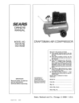
The operation of any power tool can result in foreign objects being
thrown into the eyes, which can result in severe eve damage. Always
wear safety goggles complying
with ANS Z87.1-1968
before
commencing power tool operation. We recommend Wide Vision
Safety Mask for use over spectacles, or standard safety goggles ...
available at Sears retail or catalog stores.
THIS SAFETY SEAL OF THE
POWER TOOL INSTITUTE ASSURES YOU...
1. That the
manufacturer's
assoc;ated
w;th
,Standards
For
the
power
Seal,
Safety
are
of
tools, including
the
produced
in accordance
Underwriters'
Laboratories
particular
with
tool
applicable
and
American
National Standards (ANSI).
2. That compliance with applicable safety standards is assured by independent inspection and testing conducted by Underwriters' Laboratories (UL).
3. That every motorized
tool is inspected under power.
4. That every tool has with it adequate
rules for the protection of the user.
5. That the tool manufacturer
is a sponsor
2
Copyright
of the
1969
by
Institute's
Powe
r Tool
instructions and a llst of safety
is a member of the Power Tool Institute and
Consumer
Institute,
Safety
Inc.
AI_
Education
r_ghts
reserved.
Program.
SAFETY INSTRUCTIONS
TO OPERATOR
WARNING:
Do not connect power cord
until the following
steps have been
satisfactorily completed:
a. READ CAREFULLY AND UNDERSTAND THE FOLLOWING INSTRUCTIONS and the "SAFETY RULES
FOR POWER TOOLS" ON PAGE 2.
b. Examination and operating familiarity with ON-OFF
switch, elevation control, bevel control, miter gauge,
and rip fence.
CAUTION: Always disconnect the power
cord when removing the table insert,
changing the cutting tool, or making
adjustments.
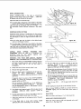
1. The saw should be bolted down if there is any tendency
to tip over or move during normal operations. The
saw table should be approximately
36-inches above
the floor.
2. The saw work area should have adequate overhead,
non-glare light and adequate surrounding work space.
3. The saw should be positioned so neither the operator
nor a casual observer is forced to stand in line with
the saw blade.
4. Kickbacks can cause Serious injury. A "kickback" occurs
when a part of the workplece binds on the saw blade or
binds between the saw blade and the rip fence or other
fixed object, rises from the table, and is thrown toward
the operator. Kickbacks are usually caused by one or
more of the following conditions:
a. Failure to use a spreader when ripping, or failure to
maintain the spreader.in alignment with the saw
blade.
b. Improperly conditioned (dull) saw that permits the
material to pinch on the out-feed edge of the saw
and rise from the table.
c. Failure to determine that the rip fence and the saw
blade are parallel to one another.
d. Ripping wood that has a twisted grain, does not
have a straight edge to guide along the fence, or
wood that is twisted or not flat (which may rock on
the table and pinch the blade).
e. Confining the cut-off piece when ripping or crosscutting.
f. Ripping by applying the feed force to the section
of the workplece that will become the cut-off (free)
piece (feed force when ripping should always be
applied between the saw blade and the fence -- use
push stick for narrow or short work).
g. Releasing workplece before operation is complete;
not pushing the workpiece all the way past the saw
blade.
5. Injury from kickbacks can be prevented
by:
or minimized
a. Avoiding any of the causes noted above;
b. Making sure by trial before starting the cut that the
anti-kickback pawls will stop the kickback once it
has started (sharpen all points if they do not);
c. Keeping your face and body always out of line of
possible kickbacks, including turning the switch ON
and OFF.
d. Always wearing safety goggles.
e. Never use both the rip fence and miter gauge during the same operation.
6. A large proportion of tilting arbor saw accidents is
caused by dull, badly set, improperly filed cutting tools,
by gum or resin adhering to cutting tools and by fence
misallgnment (out of parallel) with the saw blade. Such
conditions cause the material to stick, jam, stall the saw,
or kick-back at the operator. Cracked saw blades should
be discarded immediately. A saw blade can become
cracked if it wobbles or if it is not in balance. NEVER
ATTEMPT TO FREEA STALLED SAW BLADE WITHOUT
TURNING THE SAW OFF. Avoid potential injury by
proper cutting tool and machine maintenance.
7. Gloves should not be worn while operating the saw.
Loose flowing garments, jewelry (rings, wrist watches,
etc.), and neckties should never be worn. Long sleeves
should be rolled to above the elbows.
8. To protect your eyes, always wear safety goggles. In
addition, wear a face shield to protect against flying
particles. Ear protectors (ear plugs or muffs) should be
used during extended periods of operation.
9. Provide proper support for the workpiece, based on its
size and the type of operation to be performed; hold
the work firmly against the gauge or guide. Use a push
stick when ripping short work (under 6-inches long), or
narrow work. A push block or miter gauge hold-down
should be used when dadoing or molding.
10. Never use a length stop (such as the fence when crosscutting) on the free end or edge of the workpiece. Never
hang onto or touch the free end of workpiece, or a free
piece that is cut off, while power is "ON" and/or the
sawblade is rotating. In short, to guard against kickbacks or other potential accidents, the cut-off piece in
any thru-sawing operation must never be confined -- it
must be allowed to move laterally. Never use the rip
fence when cross-cuftlng, or the miter gauge when
ripping.
11. Cross-cutting operations are more conveniently worked
and with greater safety if an auxiliary wood facing is
attached to the miter gauge using the holes provided.
12. Do not leave a long board unsupported so the spring
of the board causes it to shift on the table. A support
should be used to catch the end of the board behind the
blade.
13. Never climb on or near the saw. Serious injury could
occur if the tool is tipped or if the cutting tool is accidently contacted. Never leave the saw with power on,
or before the cutting tool has come to a complete stop.
14. Avoid awkward operations and hand positions,
a sudden slip could cause a hand to move into
blade or other cutting tool. Never reach in back
cutting tool with either hand to hold down the
piece.
where
a saw
of the
work-
15. Make sure the top of the arbor or cutting tool rotates
toward you when standing in normal operating position.
Also make sure the cutting tool, arbor collars and arbor
nut are installed properly. Keep the cutting tool as low
as possible for the operation being performed. Keep
all guards in place whenever possible.
16. Do not use any blade or other cutting tool marked for
an operating speed in excess of the design speed of the
saw. Never use a cutting tool larger in diameter than
the diameter for which the saw was designed. For
greatest safety and efficiency when ripping, use the
maximum diameter blade for which thesaw is designed,
since under these conditions the spreader is nearest
the blade.
(Continued on Next Page)
SAFETY INSTRUCTIONS
TO OPERATOR
17. Adjust table inserts flush with, or slightly
table top.
21. Never perform any operation "freehand."
This term
means feeding the stock into the saw blade or other
cutting tool without using the miter gauge, rip fence,
taper jig, or some other device which prevents rotating
or twisting of the workpiece during the operation.
below, the
18. For operations which do not permit the use of a spreader, serious consideration should be given to the use of
jigs or fixtures to hold the work so the hands of the operator are removed a safe distance from the point of
operation.
22. Never turn your saw "ON" before clearing the table
of all objects (tools, scraps of wood, etc.) except the
workpiece and related feed or support devices for the
operation planned.
19. The use of abrasive or cut-off wheels, or wire wheels
can be dangerous and is not recommended. (Abrasive
or cut-off wheels are ,used to saw many different materials including metals, stone, and glass.)
23. Safety is a combination of operator common sense and
alertness at all times when the saw is being used.
20. Objects can be thrown upward toward the operator by
the back of the blade if proper operating procedures
are not followed. ?his usually occurs when a small loose
piece of wood or other object works around to the rear
of the revolving blade. It can usually be avoided by removing all loose pieces from the table immediately
after they are cut off, using a long stick of wood, and
by keeping the guard and spreader in place at all times.
Use extra caution when the guard assembly is removed
for dadoing or molding, and replace the guard as soon
as that operation is completed.
24. Do not cycle the motor switch on and off rapidly, as this
may cause the saw blade to loosen. In the event this
should ever occur, allow the saw blade to come to a
complete stop and retighten the arbor nut normally, not
excessively.
WARNING:
Do not
(gained from frequent
become commonplace.
that a careless fraction
ficient to inflict severe
allow
familiarity
use of your saw) to
Always remember
of a second is sufinjury.
CONTENTS
Unpacking and Pre-Assembly Instructions
Power Supply and Motor Data ...........
Assembly and Adjustments
................
Operating Controls .......................
....
Page
4
5
6
16
Maintenance
Screwdriver (medium)
Screwdriver (small)
Pencil
Page
17
18
22
24
3/8-1nch wrench
7/16-inch wrench
Square
]J (combination square,
Pliers
..............
NEEDED
_
I_
Lubrication
Proper Operating
Procedures ..............
Trouble Shooting ........................
Repair Parts ............................
TOOLS
_
and
Small steel scale
_
1/2-inch wrench
9/16-1nch wrench
NOTE: An arbor wrench and shaft wrench,
for removing or installing the saw arbor nut,
and all necessary hex-"L" wrenches are supplied with the saw. (Refer to the "'Loose
Parts List.")
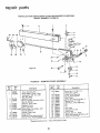
unpacking and pre-assembly
4
S
6
Figure
t
t
t
t
15
16
17
18
1
ii
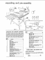
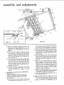
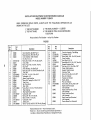
UNPACKING
AND
CHECKING
CONTENTS
This Craftsman Motorized Floor Saw is shipped complete
in one carton. In order to prevent damage during shipment
and facilitate packaging, certain items are removed at the
factory and must be assembled when receiyed by the purchaser. These "loose" parts are listed below and should be
accounted for before discarding any packing material.
Key No.
IFig.1)
1
2
3
4
5
6
7
8
9
10
11
12
13
14
15
16
17
18
19
Item Name
Key No.
(Fig. 1)
4
4
1
1
1
2
I
1
1
1
1
1
2
2
1
1
1
1
1
List of Loose Parts, BasicSaw (Package15, figure 1)
Spacer, Fence Guide Bar ......................
Screw, Mach., Rd.-Hd. Slotted, 1/4-20 x 2" ........
Nut, Hex., 1/4-20 ............................
Washer, Lock, 1/4 ............................
Wrench, Hex., 1/16" ..........................
Wrench, Hex., 3/32" ..........................
7
7
7
7
1
1
Qty.
II
Wrench, Hex., 1/8 ...........................
1
Wrench, Hex., 5/32" ..........................
1
Wrench, Hex., 3/16" ..........................
1
Key, Switch ..................................
2
List of LooseParts,AuxiliaryFence (Package16, figure 1)
Clamp, Table Extension........................
2
Screw, Mach., Hex.-Hd.,5/16-18 x 3/4" ..........
4
Nut, Hex., 5/16-18 ............................
2
Washer, Lock, 5/16 ...........................
4
Nut, Wing, 5/16-18 ...........................
4
Qty.
Leg Base .....................................
Stiffener, Leg .................................
Fence, Auxiliary ...............................
Extension Assembly, Table Sliding ................
Support, Table Extension ........................
Extension, Table ..............................
Guard Assembly, Saw ...........................
Gauge Assembly, Miter .........................
Fence Assembly, Rip ...........................
Wrench, Arbor .................................
Wrench, Shaft .................................
Bar Assembly, Fence ...........................
Rack, Table ..................................
Rod Assembly, Extension ........................
Package Assembly, Loose Parts (Saw) ..............
Package Assembly, Loose Parts (Auxiliary Fence) .....
Package Assembly, Loose Parts (Leg) ..............
Package Assembly, Loose Parts (Extension).........
Owners Manual ................................
Item Name
List of LooseParts, LegAssembly(Package17, figure
Screw, Mach., Hex.-Hd.,5/16-18 x 5/8" ...........
Nut, Hex., 5/16-18 ............................
Screw, Mach., Hex..Hd., 1/4-20xl/2"
...........
Nut, Hex., 1/4-20 ............................
Nut, Hex., 1/2-13 ............................
Foot, Leveling ................................
List of LooseParts, Extension(Package18, figure 1)
Screw, Mach., Hex.-Hd.,5/16-18 x 1-1/4" .........
Nut, Hex., 5/16-18 ............................
Washer, Lock, 5/16" ..........................
Support, ExtensionRod ........................
POWER
MOTOR
SUPPLY
AND
MOTOR
1)
16
!6
15
16
8
4
8
8
8
2
DATA
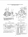
SPECIFICATIONS
The AC motor used in this saw is a single voltage capacitor
start capacitor run, non-reversible type, with the following
specifications:
Voltage ..........................
Amperes ....................
.......
240
7.0
assembly and adjustments
GROUNDING
BLADE
_S
I!'y/Z-//'
f_ _
I
'EG
LING
FOOT
NUTS,
HEX.
/ iI -13
x
// I''_
END
./'_I
Jfl
/
I
ADAPTER IS I _
AVAILABLE
FORI
NO
" II TH's
TYPE
LU°I
Figure 3
MOTOR
J
SPECIFICATIONS
_
J
!
Figure 4
OVERLOAD
I
I
INNER
HOLES
|
I
Figure 5
Figure
6
HOLES
Heavy loads, however, require that voltage at motor
terminals be not less than the voltage specified on
nameplate.
60
Single
3450
.
Clockwise
CAUTION: This saw is wired for operation
on 240 volts only. Connect to a 15 ampere
branch circuit protected by a 15 ampere
time delay or circuit saver fuse or circuit
breaker.
Most motor troubles may be traced to loose or incorrect
connections, overloading, reduced input voltage (which
results when small size wires are used in the supply
circuit) or when the supply circuit is extremely long.
Always check connections, load and supply circuit when
the motor fails to perform satisfactorily. Check wire sizes
and lengths with the table in the next paragraph. Replace or repair damaged or worn cord immediately.
WIRE
SIZES
The use of any extension cord will cause some loss of
power. To keep this to a minimum and to prevent overheating and motor burn-out, use the table below to determine the minimum wire size (A.W.G.) extension cord. All
cords should be 3-wire, grounded.
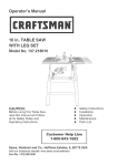
WARNING:
Do not permit fingers to contact the terminals of power or motor plugs
when installing or removing the plug to
or from a live power source. Hold the plug
as shown in figure 3.
MOTOR
SIDE STIFFENER
PROTECTORI
(Cont°d)
Hertz (cycles) ......................
Phase .........................
RPM ...........................
Rotation (viewed from left side
when facing saw at operator
position ...................
3/4x5/16
STIFFENER
I
"
_
Extension Cord Length
SAFETY PROTECTION
50
50
100
150
200
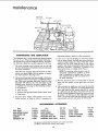
The saw motor is equipped with a manual-reset thermal
overload protector, designed to open the power line circuit
when the motor temperature exceeds a safe value. (See
figure 4.)
1. If the protector opens the line and stopsthe saw motor,
press the saw switch to the "OFF" position immediately
and allow the motor to cool.
ft.
ft.
ft.
ft.
ft.
or
to
to
to
to
less
100
150
200
400
ft.
ft.
ft.
ft.
Wire Size A.W.G.
14
12
10
8
6
NOTE: For circuits of greater length, the wire
size must be increased proportionately in order
to deliver ample voltage to the saw motor.
2. After cooling to a safe operating temperature, the overload protector can be closed manually by pushing in the
red button on the motor terminal box cover. If the red
button will not snap into place immediately, the motor
is still too hot and must be allowed to cool for a while
longer.
3. As soon as the red button will snap into running position,
the saw may be started and operated normally by
pulling the saw switch to the "'ON" position.
4. Frequent opening of fuses or circuit breakers may result
if motor is overloaded, or if the motor circuit is fused
with a fuse other than those recommended. Do not use
a fuse of greater capacity without consulting the power
company.
5. Although the motor is designed for operation on the
voltage and frequency specified on motor nameplate,
normal loads will be handled safely on voltages not
more than 10% above or below the nameplate voltage.
ASSEMBLY
AND
ADJUSTMENTS
1. Remove the "'loose" parts; clean the parts and the
basic saw assembly thoroughly. (See figure 1.) Items
having a rust-preventive coating, (saw table, etc.) may
be cleaned with a cloth saturated with kerosene. Wipe
other parts with a clean, dry cloth.
CAUTION: Before attempting
to use the
saw, assemble it as outlined in the following instructions. All adjustments are carefully checked prior to shipping the saw.
However_ rough handling in transit may
necessitate some readjustments.
2. Assemble the basic saw assembly and check all adjustments as outlined in the following instructions:
a. Installation of Legs.
(1) With saw upside down, install legs and leg stif6
J
EXTENSION ROD
SUPPORTS
Figure
Figure 7
SMALL STEEL SCALE
TABLE
EXTENSfON
8
,_
FENCE GUID_ BAR
RACK
SWITCH
BOX
SCREW
Figure 9
Figure
10
ii
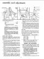
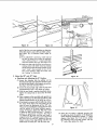
feners. (See figure 5.) Using parts from the correct
loose parts bag, assemble the legs to the saw base
with the sixteen 5/16-18x5/8
inch screws and
5/16-18 nuts. (See figure 6.) Leave these screws
loose in order to facilitate mounting the stiffeners.
All four leg stiffeners are identical and since the
distance on the sides is greater than the distance
on the ends, the leg stiffeners used on the sides
should be attached at outer holes while the
stiffeners at the ends should be attached at inner
holes. (See figure 6.)
(2) Assemble the four stiffeners with sixteen 1/420 x 1/2 inch screws and 1/4-20 inch nuts. After
stiffeners are all in place, tighten all screws
securely. Install
leveling
feet, each with 2
1/2-13 x 3/4 x 5/16 hex nuts. (See figure 6.)
(3) Place the saw in an upright
b. Installation
position on its legs.
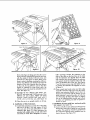
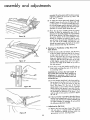
of Side Extensions.
(1) Install table extensions on each side of the table
with four 5/16-18x 1-1/4 inch screws, 5/16-18
inch nuts and 5/16 inch Iockwashers in each
extension (See figure 7.) These extensions are
provided with multiple holes on both sides (front
and back) to make them adaptable to various
table mountings. Position the extensions to the
sides of the table so the four holes in the table
and the extensions are aligned when the table
and extensions are correctly mated. An extension
rod support should be located under each end
screw at left-hand side of the saw. (See figures
7 and 8.) Leave screws snug (not tight). Be sure
to position the extension rod supports as shown
in figure 8.
(2) Place a small steel scale across saw table edge
and table extensions edge and, using the rubber
mallet, tap extensions slightly up or down (or
forward and rearward) until the surface of each
table extension is even with surface of table top
and front edge of table. (See figure 9.) Tighten
nuts on all attaching bolts securely and recheck
to make sure tightening nuts did not permit extension to move.
c. Installation of fence guide bar, rack and switch
box support. (See figure 10.)
(1) Insert a 1/4-20 x 2 inch, slotted round-head screw
through the center hole of guide bar and through
a spacer. The guide bar should be positioned so
the scale faces upward, and is readable from the
front of the saw. (See figure 10.)
assembly and adiustments
SIDE VIEW
4
3
4
SAW TABLE
SPACER
2
1
/
5
GUIDE BAR
RACK
SCREW
/4 - 20 x 21N._
LOCKW_
Figure
SWITCH
BOX
11
Figure
(2) Attach this assembly to the center hole in the
table and secure the assembly with a 1/4 inch
Iockwasher and I/4-20
inch hex nut. Do not
tighten the nut until all attaching screws are in
position.
(3) Place each rack in position (as shown in figure
11) and insert a 1/4-20 x 2 inch slotted round
head screw through the outside hole, through the
guide bar, spacer and table extension. Secure
with a 1/4 inch Iockwasher and 1/4-20 inch hex
nut. (See figure 10.)
(4) Place switch box in position (either to right hand
or left hand side of saw table as desired). Attach
with two 1/4-20 x 2 inch slotted round head
screws through switch box mounting flange, rack,
guide bar, spacer and table. Secure with two
1/4 inch Iockwashers and 1/4-20 inch hex nuts.
(See figures 10 and 11.)
(5) Complete attachment of opposlte rack with two
more screws, aligned with table in the same
sequence described above. Tighten all screws
securely.
d. Installation
of Auxiliary
(See figure 12.)
4
Fence and Extension.
NOTE: This adjustable, auxiliary fence and extension was designed for use on the left-hand
side of the saw (when facing the saw at operator's position).
(1) Attach the table extension support (1, figure 12)
to outside edge of left-hand table extension with
12
two 5/16-18 x 3/4 inch screws (5), 5/16-18 inch
nuts and 5/16 inch Iockwashers in position as
shown in figure 12. Do not tighten the screws fully.
(2) Slide the extension slide rod (2) through each
rod support (3) and through the hole in each end
of the support (I). It will be necessary to slide
these rods from under the table because of the
retaining rings.
(3) Attach the sliding extension (9) to each rod (2)
with a 5/16-18 x 3/4 inch screw (5) and 5/16 inch
Iockwasher in the end of each rod. Do not tighten.
This extension should be positioned as shown in
figure 12.
(4) Move the end of sliding extension in. Level the
sliding extension (9) with the table extension.
Tighten 5/16-18 x 3/4 screws (5) in the extension
slide rods (2). Move sliding extension out and
tighten 5/16-18 x 3/4 screws (5) attaching the
support (1) to the extension. If binding is experienced, tap the rod supports (3) in the proper
direction to relieve interference.
(5) Position an extension clamp (7) over each rod
and through the mating hole in support (1). Secure
each extension clamp with a wing nut (8).
(6) Attach the auxiliary fence (6) with the wing nuts
(8), as shown in figure 12.
e. Adjust the Table Insert. (See figures 13 and 14.)
(1) Press down on table insertwith fingers to make
sure it is properly secured in the table opening.
(2) Using a small scale or straightedge, check at
FLEVATIOI_
CRANK
KNOB
TILT CRANK-
-----C.
-LEVATION
.OCK
Figure
13
Figure
14
KNOB
Figure 15
each of the four set screw positions to determine
if the table insert is even with saw table surface.
(See figure 13.) If uneveness exists, adjust as
follows:
(a) If an adjustment is necessary, rotate each of
the four set screws (or as many as required)
with a 3/32 inch hex-"L'" wrench until table
and insert surfaces are even. (See figure 14.)
(b) Make sure that ends of all four set screws are
making contact with table recess by pressing
on the insert at each set screw location. If the
insert "rocks" when pressed at any of the
four screw locations, adjust set screws until
the "'rocking" is eliminated.
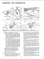
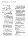
3. Adjust the 90 ° and 45 ° Stops.
a. Checking and Adjusting the 0 ° Position
(1) Loosen the elevation lock by pulling out the
elevation lock knob and rotate the elevation crank
to raise the saw blade to the deepest cut position.
(See figure 15.) Push elevation lock in.
(2) Loosen the clamp knob and rotate the tilt crank
counterclockwise until it will rotate no farther.
Figure 16
/
(3) With the saw blade in position described above,
tighten the clamp knob to secure the tilt mechanism.
(4) Place a square on the saw table and against saw
blade. (See figure 16.) The blade should be at 90
degrees (perpendicular) to the table top surface.
(5) If the blade is not square with the table top, loosen
the clamp knob (figure 15) and rotate the tilt
crank to move the mechanism off the 90 ° stop.
This can be accomplished by rotating the tilt crank
until the pointer on tilt scale indicates approximately 10 degrees. Rotate the 90 ° stop screw
in table top with a 3/16-inch hex-"L" wrench to
produce an approximate correction. (See figure
17.) Rotate the tilt crank until the saw blade is
stopped by the 90 ° stop screw and recheck with
the square for an exact 90 ° position of the saw
blade. Continue these trial settings until the saw
blade stops at exactly 90 ° with the table top.
STOPSCREW 45°
STOPSCRE_
Figure 17
(6) When the saw blade is adjusted squarely with
the table top, check the pointer on the tilt gauge,
which should be positioned at exactly "0" (zero)
degrees. (See figure 15.) If not at zero, loosen
the attaching screw and align pointer with the
"0" mark, then tighten the screw.
assembly and adjustments
ARBOR WRENCH
\
SHAFT
ELEVATION
CRANK
WRENCH
POINTER
q
CLAMP
KNOB
TILT
aASE OF
COMBINATION
SQUARI
ELEVATION
Figure
18
Figure 20
Figure
sc,_
//!
KNOB
/
REAR
OF SAW
PENCIL
REAR OF
LOCK
MARK
SCALE
PENCIL
SAW
MARK
Figure 21
Figure
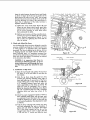
b. Checking
and Adjusting
the 45 ° Position
b. Pull out the elevation lock knob (figure 20) to release
the elevating mechanism and, using the elevation
crank, position the saw blade for the deepest cut in
preparation for aligning the saw blade with table
grooves. Push in on the elevation lock knob.
(1) Loosen the clamp knob and rotate the tilt crank
clockwise until it will turn no farther. Tighten the
clamp knob. At this point, the acute angle made
between the saw blade and table top should be
45 degrees. (See figure 18.) The base of a combination square (or protractor) can be used effectively for this measurement.
c. Loosenthe clamp knob, and rotate the tilt crank clockwise until it stops(pointer at 0°). (See figure 20.) This
will position the saw blade vertically. Tighten the
clamp knob.
(2) If the angle between the saw blade and table
top is not 45 °, loosen the clamp knob and rotate
the tilt crank counterclockwise until the pointer
on tilt gauge indicates approximately 40 ° . Rotate
the 45 ° stop screw in table top with a 3/16-inch
hex-"L" wrench to produce an approximate correction. (See figure 17.) Rotate the tilt crank until
the. saw blade is stopped by the 45 ° stop screw
and recheck for the exact 45 ° blade position.
Continue these trial settings until the saw blade
stops at exactly 45 ° with the table top.
d. Make a pencil mark on the saw tooth that is just above
the table top at rear of the blade. (See figure 21.)
e. Place the miter gauge in the table groove at left of
saw blade. Make sure the miter gauge is set at "0".
f.
Saw Blade
With Table
Lay a soft-lead pencil in the depression just ahead
of the miter gauge scale, with the pencil point toward
the blade. (See figure 21.) Hold the pencil in the
depression with thumb of left hand as shown in figure 21.
g. Slide the miter gauge to a position which will
the pencil at the marked saw tooth. Hold a
scale against the marked tooth and slide the
toward the saw until the point rests against the
With the left thumb, hold the pencil securely
NOTE: If the above adjustments have been 'performed accurately, the saw will now have a
positive stop at "'0" (90 ° position) and "45"
degrees. The pointer on the tilt scale should
indicate both positions accurately.
4. Aligning
22
miter
gauge
head.
It must
not
point
small
pencil
scale.
in the
move.
h. With the right hand, remove the scale and rotate the
saw blade until the marked tooth is just above the
saw table at the front. (See figure 22.)
Top.
a. Remove the table insert and check the saw arbor
nut to make sure it is tight. Use the shaft wrench on
arbor flats and arbor wrench on the arbor nut, as
shown in figure 19. Install the table insert.
i.
10
Slide the miter gauge toward the front of saw table
until the pencil is pointing toward the marked tooth.
Insert the scale between the pencil point and blade,
as shown in figure 22. If the saw is parallel to the
table groove, the scale will just "slide" into the gap
between the pencil point and blade. If the scale will
not enter this gap, or is loose in the check shown in
figure 22, an adjustment of the table trunnlons is
required. Proceed as follows:
(1) Tighten the clamp knob firmly (figure 20) and
loosen the two screws which secure each table
trunnion (front and rear) to the table. (See figure
23.) It will be necessary to reach these screws
from underneath the table.
(2) Shift the two trunnlons until the preceding measurements are equal and tighten all four trunnion
screws. Recheck measurements (figures 21 and
22) to make sure tightening the screws did not
alter the setting.
@
5. Check and Adjust Rip Fence
Your Craftsman Rip Fence has been designed to provide
accuracy, reliability and long life. In order for your fence
to work properly it is imperative that it be adjusted
accurately. The fence is adjusted at the factory, but due
to shipping hazards and slight tolerance build-up between individual saws, it is sometimes necessary that
your fence be adjusted to your particular saw. Therefore,
check your fence and adjust it (if necessary) as outlined
in the instructions that follow:
Figure 23
FENCE
ASSY
LOCK
HANDLE
inn
CAUTION: It is imperative that these instructions be followed precisely, as an incorrect adjustment could damage the fence
and the fence guide bar attached to your
FENCE
FENCE
saw.
GUIDE
a.
Installation
ADJ.
KNOB
BAR
_
_
of Rip Fence
(1) Raise the lock handle and position the rip fence
(10, figure 1) on the saw table. Do not latch the
lock handle.
NUT
(2) Slide the rip fence along the guide bar while
watching the clearance between lower edge of
fence and table top. If any portion of the fence
(except sliding pad at rear) drags on table top,
or if clearance between fence and table top
varies appreciably
as the fence is moved, the
guide bar must be readjusted. This is accomplished by loosening the attaching screws (figure
10) and re-positioning the bar until a consistent
clearance exists over entire top surface of the
table.
(],4
- 20).__
SAW TABLE
_
_N,
SCREW (1/4
F ENCpE NAt_N
SHAF T
- 20 x 2 IN.)
SPACER
Figure 24
(3)Check for proper engagement (mesh) of teeth on
fence adjusting shaft pinion with the gear teeth
on underside of rack. (See figure 24.) The pinion
should be adjusted up or down so that teeth are
in full contact lengthwise. This adjustment is made
as follows:
(4) Push the fence adjusting knob all the way down
and look underneath the rack to determine if
pinion and rack teeth are aligned. (See figure
24.) If the pinion extends too far (or not far
enough) loosen the set screw (1, figure 25) with
a 1/8 inch hex-"L" wrench and slide the knob
2
11
assembly and adjustments
assembly (2) on the pinion shaft to achieve proper
alignment. Tighten the set screw (1) with a 1/8
inch hex-"L" wrench.
(5) To adjust for correct gear mesh (depth of tooth
contact), loosen the set screw (3, figure 25) with
a 1/8 inch hex-"L" wrench and rotate the eccentric (4) until proper mesh is obtained. Tighten the
set screw (3) after adjusting and check for proper
operation at various points along the rack.
(6) Move the rip fence carefully across the central
portion of table, by rotating the gear knob, to
determine if the teeth engage the rack properly
at the center division. The fence should pass over
the center division of the rack smoothly. If any
binding or resistance is noticed it may be necessary to loosen the guide bar attaching screws at
one end and at the middle, and shift the rack
enough to properly space the teeth at the center
division. Several trials may be necessary.
Figure 26
b. Checking for Parallelism
Table Groove.
of Rip Fence with
(1) With
the lock handle not latched, slide the fence
on the saw table so the front edge of the channel
is flush with the side of one of the two miter
grooves. (See figure 26.) This can be checked by
using your fingers as shown to "feel" for correct
alignment. Shift the rear of the fence to the right
or left slightly, causing fence not to be squcre
with the front edge of the table nor pr_allel to
the miter groove.
DOWN
TO LOCK
Figure
27
(2) Push down on the lock handle carefully (do not
force) while watching the rear of the fence for
its correcting action.
CAUTION: Do not force the lack handle. If
the handle does not lock down readily, an
adjustment is necessary-and
to force it
could cause damage to both the fence and
and guide bar.
FENCE
(3)
PAWL
Figure 28
The lock handle should lock in the down position.
Do not force the handle, as it is not necessary for
the handle to be all the way down to lock the
fence. (See figure 27.) The rear of the fence
should move to correct itself, and do so parallel
(flush) with the miter groove in saw table throughout its full length. Alignment may be checked with
the forefingers to determine if the fence is flush
with the side of miter groove, as shown in figures
26 and 27.
(4) If the lock handle responded as described above,
and the fence aligned itself with the table groove
at both ends, the fence is properly adjusted and
no further attention is necessary. If not, perform
the following adjustment routine.
€. Adjusting
Figure
the Rip Fence
(1) Remove the fence and turn it over. Then, with a
1/8 inch hex-"L '° wrench, loosen the pawl set
screw (located just behind the fence pawl) approximately two turns. (See figure 28.)
29
12
SCALE
(WITH
MIRROR
SURFACE)
WINDOW
REFLECTED
(2) Using a 5/32 inch hex-"L'" wrench, loosen the
set screw at the rear of the fence approximately
two turns. (See figure 29.) This screw is located
in the fence lock just inside the channel as shown.
29.) Check to see if rear of fence is "secure"
the table at the rear.
the fence back on saw table and notice
that the lock handle offers no resistance at any
position.
(4) Push the lock handle down in "locked" position
and, using a 1/8 inch hex-"L" wrench inserted
into the fence pawl set screw from underneath the
saw table, tighten the set screw finger tight. (See
figure 30.) Do not use wrench or pliers--finger
tight only.
(10) After adjusting the fence on the saw table, move
it to one of the table extensions and re-check the
adjustment, as even the slightest difference in
length between the extensions and saw table
would affect the fence adjustment to some degree.
If one is slightly shorter than the other it would
be evidenced by a lighter "feel" of the fence
lever when locking it. If a difference in "feel" is
apparent, readjust the fence on the shorter member and it will, in turn, lock effectively on the
longer member.
(5) Raise the lock handle, push the fence to one side
(off square) at the rear. Then lock the fence with
the lock handle, while watching to make sure it
"'corrects" itself. Repeat this operation two or
more times. The fence should "'correct'" itself each
time it is locked.
d. Aligning
(6) Raise the lock handle and align the fence with
the miter groove (at the front end of the groove)
as shown in figure 26. Push the lock handle down.
(2) Position the rip fence on the right-hand side of
the saw blade with the fence channel one-inch
from the blade and lock the fence. Be sure to
use one of the teeth bent (set) to the right of
blade. Measure from this to the fence, since this
determines your width of cut. This distance should
be measured accurately with a scale.
(8) Check
for "automatic correcting" by releasing
the lock lever, shifting the fence off square at
the rear, then locking it. The fence should square
and
be
flush
(parallel)
Rip Fence Plastic Indicators
(1) If for any reason the tilt handle has been rotated
during preceding operations, loosen the clamp
knob (figure 20) and rotate the tilt crank clockwise until it stops (tilt pointer at "0"). Tighten
the clamp knob.
(7) Check for correct alignment with saw table groove
for the full length of the fence. If it is aligned at
the front but out of alignment at the rear, loosen
the two hex-head screws on top of the channel
near the front (figure 31) and tap the channel at
the rear with one hand until it is aligned with
the table groove. Tighten the two hex-head screws
securely and recheck. More than one trial may
be required, as tightening the screws may change
the setting slightly.
automatically
to
NOTE: If the fence fails to square itself everytime, check for any burr or foreign material on
the surface of the fence head where it contacts
the saw table. Also check for nicks or burrs in
edges of saw table. Stone off any irregularities
these surfaces.
on
(3) Place
itself
IMAGE
.. Figure 32
Figure 31
(3) Set the right-hand indicator (a scribed line in
the plastic window) to "1" inch on the gulde-bar
scale. This is accomplished as follows:
with
(a) A close look will show a reflection of the
indicator line on the mirror surface of the
guide-bar scale. In order to make sure that
you are sighting squarely above the scale,
move your eye until the indicator line and its
reflected image coincide. (See figure 32.)
the miter groove each time the handle is locked
down.
(9) Lock the fence with the lock handle, using a 5/32
inch hex-"L" wrench, tighten the fence lock set
screw at the rear, hand tight only. (See figure
13
assembly and adjustments
INDICATOR
IN
LINE
a. Checking the Miter Gauge
PLASTIC WINDOW
(1) Loosen the lock handle and push the stop pin
firmly into the middle detent ("0'" position on the
scale.) The stop pin will be seated more effectively if it is rotated slightly as it is being "'pushed'"
into the detent. Tighten the lock handle. (See
figure 34.)
Figure 33
NOTE: Always tighten the lock handle handtight only. Do not use a wrench on the lock
handle.
SCREWS
LOCK
(2) Using a combination square, check for an exact
90-degree angle between the miter gauge and
rod assembly. If this measurement is exactly 90
degrees, the adjustment has not been disturbed
and the gauge is ready for use. If not accurate
at 90 ° , adjust the gauge as follows:
HANDLE
STOP
PIN
SQUARE
INDICATOR
ROD ASSEMBLY
b. Adjusting the Miter Gauge
(1) Loosen the lock handle, disengage stop pin, hold
the square solidly against the rod assembly and
face, then tighten the lock handle firmly by hand.
Recheck to make sure that tightening the lock
handle did not alter the setting. Remove the
square from the gauge.
(2) Loosen the two screws that attach the indicator
block to the rod assembly. Shift the indicator
block until the stop pin can be pushed solidly into
its detent. Hold the indicator block aligned with
the rod assembly and the stop pin seated firmly
in the detent and tighten the two screws.
(3) Loosen the lock handle and recheck for accuracy
with the square. (Make certain the stop pin is
fully seated.) Tighten the lock handle and readjust
if necessary.
(4) After completing the above adjustment, loosen
the pointer attaching screw, set pointer at "0"
(zero) and tighten the screw.
NOTE: Detents at the two 45-degree positions
are jig bored. When the gauge is adjusted for
a 90-degree cut, the 45-degree positions are
correct.
BLocK
Figure 34
(b) If an adjustment is required, loosen the two
screws (one at each end of the window) and
shift the plastic window until the indicator line
is aligned with the "'1" inch line on the scale.
(See figure 33.) Tighten the two screws and
recheck for accuracy. If the plastic window
cannot be shifted enough to provide this alignmerit, loosen the screws that secure the guidebar scale to the guide-bar at its ends, shift
the scale slightly and tighten the screws. Then
proceed to adjust the plastic window as described above.
(c) When the fence is correctly adjusted and
moved to any position at the right of the saw
blade, the scale will indicate the width of the
desired cut. Make several trial settings and
check by measuring with a scale from the
fence to the blade.
NOTE: When properly adjusted, the indicators
may be used for most operations, thus eliminating the need for actual measurements except
for extreme requirements. When sighting the
indicator, always use the system shown in figure
32 in order to make sure the sight angle is
correct.
(d) Move the fence to the left-hand side of saw
blade and adjust the left-hand indicator.
(right-hand side) in the same manner as for
the right-hand indicator.
NOTE: Remember, if the guide-bar scale must
be moved when adjusting the left indicator, it
will change the settings just made on the righthand indicator and necessitate a readjustment.
7. Install and Adjust the Saw Guard Assembly.
Position the saw blade for deepest cut and against the
90 ° stop, (square with table top).
The guard assembly (8, figure 1) consists of a clear
plastic blade guard, spreader and anti-kickback. The
spreader must be aligned with the saw blade, which is
accomplished as follows:
a. Installatlan
af Saw Guard Assembly.
(See figures 35 and 36.)
(1) Loosenthe lock handle on spreader support, slide
the lower end of the spreader support on the
spreader rod (attached to end of spreader bar).
(See figures 35 and 36.)
(2) Push the spreader support onto the spreader rod
until the groove in spreader support is snug against
the groove pin. Tighten the lock handle. (See
figure 36.)
6. Check and Adjust the Miter Gauge
NOTE: This gauge was set correctly at the factory, but rough handling during shipping might
have disturbed the setting. To assure maximum
accuracy the "0 °° (zero) degree stop should be
checked and adjusted (if required) as follows:
b. Alignment af Saw Guard Assembly.
(See figures 35 and 36.)
(1) Raisethe plastic guard up to expose the spreader.
14
(2)Place
a square against the spreader and saw
table top. (See figure 36.) If the spreader bar
is not positioned at 90 ° with the table, loosen
the two clamping screws (figure 35) and rotate
the spreader bar until the spreader is square with
the table (figure 36.) Tighten the two clamping screws (figure 35) and recheck to make sure
tightening the screws did not change the adjustment. More than one trial may be required.
(3) Sight along the spreader and saw blade to check'
for alignmenl;. An alternate method is to hold a
straightedge against each side of saw blade and
notice whether or not the spreader is centered
in the gap thus formed between the straightedges.
(4) If the spreader is too far to the right or left, loosen
the hex-head set screw in outer end of spreader
bar and slide the spreader rod in or out of the
hole in the spreader bar until correct alignment
is obtained.
(5) Rotate the plastic
position.
guard
down
into operating
GUARD "_
(7) To remove the blade guard
the lock handle and slide
the spreader rod.
CAUTION: Use extra care
blade guard is removed far
cluding Dado and Molding.
_,,_ ';AK.wCLKsB
ACK
SAW
TABLE
9oo 111"
(6) For safety and to minimize kickbacks, the blade
guard and spreader must always be in place for
all thru-sawing operations. The spreader must
always be kept in proper alignment with the saw
blade so the spreader doesn't prevent pushing
the work past the blade. The blade guard will
help to prevent sawdust and splinters from being
thrown upward.
SPREADER
\
and spreader, loosen
it off. Do not disturb
lib
:
ROD
:
SETI _SPREADER
SUPPORT
SCREWl I/
LI SPREA°ER
R°D
SPREADER
J::_(-.'l_:_i__,[_;'P
K.ANOLE
GROOVE
whenever
the
operations in-
VIEW
PIN -
FROM REAR OF SAW
Figure 36
8. Adjust the Exact-I-Cut Indicator.
(See figures 37 and 38.)
The cut indicator ("Exact-I-Cut") located a few inches
ahead of the saw blade, enables the operator to determine precisely where the cut in a particular board will
occur, provided the cut indicator shoes have been correctly positioned. It should be checked and adjusted (if
necessary) as follows:
WIDTH OF CUT'-P"
SOCKET-HEAD
--
EXA(
a. Position the saw blade in the 90 ° position (0 ° on
tilt scale), by loosening the clamp knob and rotating
the tilt crank counterclockwise until it will rotate no
farther. Tighten the clamp knob.
b. With the saw running, place a straight board (preferably hardwood) against the miter gauge and hold
it securely in the miter gauge.
c. Make a small cut and pull the miter gauge back until
the cut is directly on the "Exact-I-Cut".
(See figure
37.) If both cut-indicator shoes are aligned with the
edges of the cut, no adjustment is required. If not
aligned, loosen the two socket, fiat-head screws with
a 1/16 inch hex-"L'" wrench and slide the cut indicator shoes laterally until the edge of each shoe is
aligned with its respective edge of the cut in the
board. (See figure 38.) Tighten both screws and
recheck for accuracy of the adjustment.
CUT-INDICATOR
_/I
SCREWS
-CUT
SHOES
Figure 38
15
Figure
37
operating controls
OPERATING
CONTROLS
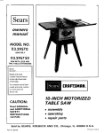
the thumb or finger against end of switch lever to prevent the switch from being turned on as the key is removed.
Before operating the saw, the operator should examine all
controls until thoroughly familiar with their functions, as
well as making sure that controls are operating properly.
(See figure 39.)
6. Rip Fence (1, figure 42). When the lock handle (2,
figure 42) is released (raised), the rip fence (1) may
be moved toward, or away from, the saw by hand.
Pushing the lock handle (2) down into locked position
will automatically align the rip fence parallel to the
table groove. This alignment correction will occur at
the front of saw table. Therefore, it may be necessary
to make more than one setting in order to produce the
exacf distance desired between saw blade and fence.
Keep the saw table and rip fence clean, as saw dust
may prevent the fence from assuming proper alignment when tightened.
CAUTION: Under no circumstances should
a blade with a diameter greater than 12
inches be used with this saw.
1. Elevation Crank (li figure 39i. Located on the front
panel to control elevation of the saw blade,
2. Elevation Lock (2, figure 39). Located on front panel
for securing the saw in desired elevated position. It is
pushed in to lock and pulled out to release.
3. Tilt Crank (3, figure 39). Located on front panel behind the elevation crank to control the angle of tilt.
The saw blade can be tilted from 0 ° to 45 °, as indicated on the TILT SCALE (5). If the angle of cut (tilt)
must be extremely accurate, the angle of the saw blade
should be checked wffh a protractor, or with a board
known to be cut at the exact angle required.
7. Lock Handle (2, figure 42). This handle is used to
clamp the rip fence in place after it has been moved
to the desired position. (Refer to preceding step 6.)
4. Clamp Knob (4, figure 39.) Located on front panel to
lock the tilt mechanism in any desired position. The tilt
mechanism should always be locked before starffng
work and should always be unlocked before attempting to change the angle of tilt.
9. Miter Gauge (4, figure 42). This gauge is used in table
grooves as a guide for the work-piece when the rip
fence is not used. The angle of the gauge can be adjusted by loosening the clamp handle (5) and positioning
the gauge as indicated by the dial and pointer on the
miter gauge (4).
8. Fence Knob (3, figure 42). This knob (when depressed)
moves a pinion into engagement with the rack teeth
to permit accurate positioning of the rip fence.
5. ON-OFF Switch and Key (6, figure 39). This unique
switch is mounted in a switch box which is attached to
the underside of saw table as shown in figure 39. To
turn the switch on, the operator inserts the key (figure
40) and hooks the forefinger of the right hand under
the end of switch lever and pulls downward. The switch
is turned off by simply pressing upward on the switch
lever. When removing the key (figure 41), always hold
10. Sliding Table Extension (6, figure 42). This extension
permits a greatly extended work area and provides an
outboard fence for handling such items as table tops,
doors, etc. Loosen wing nut (7) to adjust the extension.
Loosen wing nut (8) to raise or lower the auxiliary fence.
11. "'Exact-I-Cut" (9, figure 42). Inserted into the saw table
just ahead of the saw blade is a cut indicator shoe,
commonly called an "Exact-I-Cut".
When properly
adjusted, the cut indicator shows the operator exactly
where the edge of the cut will occur at either s_de of
the saw blade.
2
Figure 42
1
\
4
3
Figure 39
6
-KEY
Figure
40
Figure
41
16
8
maintenance
ELEVATION
LOCK KNOB
TILT WORM
LOCK
BEVEL GEARS
__
_
WRENCH
_'-/_
ELEVATING
WORM
i
MAINTENANCE
AND
LUBRICATION
adjustment purposes, should be oiled occasionally.
This Craftsman Saw is a fine machine and should be given
the best of care. If kept clean and properly lubricated, it
will provide many years of trouble-free service. The following instructions should be carefully observed at all times.
4. If the saw is to be left standing for some time, particularly in damp climates, the table top surface should be
coated with light engine oil or Sears "Stop Rust". Either
material may be easily wiped off with a cloth before
using the saw. Treat any unpainted parts and surfaces
with Sears "Stop Rust". ("Stop Rust" is available at any
Sears Retail Stores or Catalog Order House.)
1. Tilt worm, elevating worm and gears are covered with.
grease at the factory and should be checked occasionally
for proper lubrication.
NOTE: The aluminum table extensions may be
adequately protected by applying a heavy
coat of automobile or furniture wax. The wax
also enables boards to slide more easily across
the table extensions.
Clean the worm and gear teeth with kerosene or similar
solvent and repack lightly with cup grease or automotive chassis lubricant. (See figure 43.)
2. The saw motor bearings have been packed at the factory
with proper lubricant and require no additional lubrication. Other parts requiring lubrication should be oiled
frequently with SAE No. 20 or No. 30 engine oil. The
following parts should be lubricated regularly. (Refer
to exploded view drawing for the following locations,
if not apparent.)
5. Attention should be given to moving parts in the rip
fence and miter gauge, to keep them clean and lubricated.
6.
a. Table trunnions.
b. Elevation shaft directly behind elevation hand wheel.
c. Clamp screw.
3. All points where friction exists between two or more
moving surfaces, or where a slip fit is necessary for
RECOMMENDED
Item
STOP RODS ..........
HOLD DOWN CLAMP ...
HOLD DOWN SET ......
CASTERS .............
UNIVERSAL JIG .......
Cat. No.
9-29924
9-29928
9-3230
9-22201
9-3231
After extended use, slight wear may cause the elevation
lock to slip and an adjustment is required. Remove the
screw that holds the lock wrench and shift the wrench
to a different hole. (See figure 43.) If the holes do not
provide enough adjustment, remove the lock wrench and
re-position it on the hex nut. The adjustment is correct
when it is securely locked with the elevation lock knob
approximately
one-inch away from the front panel.
ACCESSORIES
Item
Item
Cat. No.
TAPER JIG ...........
DADO INSERT ........
MOLDING INSERT .....
MOLDING HEAD SET ...
MOLDING HEAD ONLY .
9-3233
9-29935
9-29936
9-3217
9-3214
DADO HEAD .........
DADO HEAD .........
BLADE STABILIZERS ....
SANDING WHEEL .....
The above recommended accessories are current and were
available at the time this manual was printed.
17
Cat. No.
9-3253
9-32473
9-4952
9-22723
proper
operating
procedures
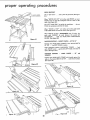
CROSSCUTTI NG
DOWN
CROSSCUTTING
CLAMP
is known
as cutting
wood
across
the
grain, at 90 °, or square with both the edge and the flat side
of the wood. This is done with the miter gage set at "'0".
The miter gage may be used in either of the grooves in the
table. Make sure it is locked.
When using the miter gage in the LEFT hand groove, hold
the workpiece
firmly
against the miter gage head with your
left hand, and grip the lock handle with your right
... or
use Hold-Down
Clamp
(Optional
Accessory)
(See figure
44.)
Figure 44
When using the RIGHT hand groove, hold the workpiece
with your right hand and the Iockhandle with your left
hand.
RODS
REPETITIVE
CUTTING
REPETITIVE CUTTING is known as cutting a quantity of
pieces the same length without having to mark each piece.
Use the Stop Rods (Optional Accessory) for cutting pieces
6 inches long or longer. (See figure 45.)
Figure
When making repetitive cuts shorter than 6 inches, DO
NOT USE THE RIP FENCE AS A LENGTH STOP ...
BECAUSE
THE
CUT OFF
PIECE COULD
BIND
BETWEEN THE FENCE AND BLADE AND CAUSE A
KICKBACK.
45
ALWAYS clamp a block of wood at least 2 inches thick and
3 inches long to the table to act as a length stop. (See figure
46.)
BLOCK
1. Slide the workpiece along the miter gage until it touches
the block ... hold it securely or clamp it with the
Hold-Down Clamp (Optional Accessory),
2. Make the cut ... pull the workpiece back ... push the
cut off pieces off the table with a long push stick ..,
DO NOT ATTEMPT TO PICK THEM UP AS THIS
COULD ENDANGER YOUR HANDS.
MITER CUTTING
CUT
Figure 46
'E)FF
MITER CUTTING is known as cutting wood at an angle
other than 90 ° with the edge of the wood. Follow the same
procedure as you would for crosscutting.
"
PIECES
\
Adjust the miter gage to the desired angle, and lock it.
The miter gage may be used in either of the grooves in the
table,
When using the miter gage in the LEFT hand groove, hold
the workpiece firmly against the miter gage head with your
left hand.
nnd grip the leek handle with your right ... or
use Hold-Down Clamp (Optional Accessory). (See figur0
47.)
When using the RIGHT hand groove, hold the workpiece
with your right hand and the Iockhandle with your left
hand.
Figure 47
18
BEVELCROSSCUTTING
BEVEL
CROSSCUTTING
is the same as crosscutting
except that the wood is also cut at an angle . •. other than
g0 degrees with the flat side of the wood.
Adjust the blade to the desired angle.
Use the miter gage in the groove to the RIGHT of the blade
•.. NEVER TO THE LEFT. Hold the workpiece with your
right hand and the Iockhandle with your left hand ... or
use Hold-Down Clamp (Optional Accessory), (See figure
48).
COMPOUND
MITER CUTTING
Compound miter cutting is a combination of miter cutting
and bevel crosscutting. The cut is made at an angle other
than 90 degrees to both the edg_ and the flat side of the
wood.
WORKPIECE END
I/4 IN.
Adjust the miter gage and the blade to the desired angle
•.. make sure miter gage is locked.
I/4 iN.
Figure 49
IN.
Use the miter gagein the groove to the RIGHT of the blade
•.. NEVER TO THE LEFT. Hold the workpiece with your
right hand and the Iockhandle with your left hand ... or
use Hold-Down Clamp (Optional Accessory).
2X4 HANDLE
RIPPING,
BEVEL
RIPPING,
RESAWING
AND
RABBETING
(along the edge of a workpiece)
are
performed
using the
RIP
FENCE
together
with
AUXILIARY
deviceswhen required.
WARNING:
FOR YOUR OWN SAFETY,
ALWAYS
OBSERVE THE FOLLOWING SAFETY PRECAUTIONS.
1.
Never
make these cuts
FREEHAND
(without
Figure
50
using the
rip fence or auxiliary
devices when required)
the
blade
could
bind
in the
cut
and
KICKBACK.
because
cause
a
2.
Always lock the rip fence securely when in use.
3.
Remove miter gage from table.
4.
Make sure blade guard is installed for all rip type cuts.
Replace
the
guard
IMMEDIATELY
following
completion of resawing, rabbeting, dadoing, or molding
operations.
g.
6.
Do not stand directly
in front of the blade in case of a
KICKBACK.
Stand to either side of the blade.
reach
over
or
behind
the
blade
to
pull
the
long or
pieces of
10. Do not pick up small pieces of cut-off material from the
table. REMOVE them by pushing them OFF the table
with a long stick. Otherwise they could be thrown back
at you by the rear of the blade.
11. Do not remove small pieces of cut-off material that may
become TRAPPED inside the blade guard while the saw
is RUNNING.
THIS COULD ENDANGER
YOUR
HANDS or cause a KICKBACK.
Turn the saw OFF
piece.
Pull the workpiece TOWARD you. If the PAWLS do
not DIG into the workpiece and HOLD it ... the pawls
must be SHARPENED. Refer to "Maintenance" section
further on in this manual.
Have blade extend approximately
workpiece.
Additional
blade
hazardous.
not
workpiece
through
the cut
...
to support
heavy workpieces
... to remove small cut-off
material or FOR ANY OTHER
REASON.
Frequently check the action of the ANTI-KICKBACK
PAWLS by passing the workpiece alongside of the
spreader while saw is OFF.
5.
Do
...
lift the guard and remove the
Certain ripping cuts require the use of Auxiliary
Devices.
Learn to know WHEN and HOW to use these devices for
NARROW ripping. You can make them from scraps of
wood.
1/8 inch above top of
exposure
could
be
PUSH STICK
Make one using a small piece of 1 x 2. (See figure 49.)
7.
Keep your hands clear of the blade and out of the path
of the blade.
AUXILIARY
B.
If the blade
SWITCH OFF
Make one using a piece of 3/8 inch plywood and a small
piece of 2 x 4. (See figure 50.)
stalls
before
or stops
attempting
while
cutting,
TURN
to free the blade.
19
FENCE/PUSH
BLOCK
proper operating
procedures
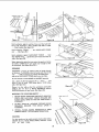
WOR K SUPPORT
Use a "saw horse" ,..
ALWAYS SUPPORT
WORKPIECES
51.)
and a piece of plywood. (See figure
When "WIDTH OF RIP" is 6 inches and WIDER use your
RIGHT hand to feed the workpiece until it is clear of the
table. (See figure 52.)
Use LEFT hand ONLY to guide the workpiece ...
FEED the workpiece with the left hand.
do not
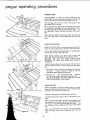
When "WIDTH of RIP" is 2 inches to 6 inches wide USE
THE PUSH STICK to feed the work. (See figure 53.)
Figure
When WIDTH of RIP is NARROWER than 2 inches, the
push stick CANNOT
be used because the guard will
INTERFERE
...
USE the AUXILIARY
FENCE/PUSH
BLOCK. (See figure 54.)
51
NARROW
RIPPING - SHORT PIECES - UP TO 18"
Position the AUXILIARY
FENCE to the desired WIDTH
OF RIP . .. lock RIP FENCE in place.
Hold workpiece against AUXILIARY
FENCE ... feed
with RIGHT hand ... guide with LEFT hand until clear of
table. (See figure 55.)
NARROW
LONGER
RIPPING
-
LONG
PIECES
-
18"
and
Position
the AUXILIARY
FENCE with handle against the
table to the desired WIDTH of RIP ... lock fence in place.
(See figure 56.)
Figure 52
I
Figure 55
Figure 53
Figure
54
I
HANDLE
Figure 56
2O
AGAINST
TABLE
EvEN
W'TH,
AOLE
Figure
Figure
58
Hold workpiece
against auxiliary
fence and feed with left
hand until
workpiece
is about EVEN
with END of table
•.. Stop Feeding. (See figure 57.)
Hold workpiece FIRMLY
over ... (See figure 58.)
...
turn AUXILIARY
BAFFLE
FENCE
Hold workpiece against AUXILIARY
FENCE ... feed
with RIGHT Hand ... guide with LEFT hand until clear of
table. (See figure 59).
Figure
60
When ripping thin strips that may enter the guard and strike
the baffle. CAREFULLY
raise guard only enough to clear
the workpiece.
(See figure 60 and 61.)
RESAWING
RESAWING is known as ripping a piece of wood through
its thickness. To RESAW a piece of wood wider than 2-1/8
inch ... it will be necessary to remove the blade guard ...
and use an AUXI LIARY FENCE which you can make.
Do not attempt to resaw BOWED or WARPED material.
Use a piece of 3/8 inch plywood 9 in. x 20 in ....
and
attach a strip of wood 1-5/8 inches thick x 2-1/2 inches
wide. (See figure 62.)
Figure
Clamp it to the table so that the workpiece will SLIDE
EASILY but not TILT or MOVE SIDEWAYS without
BIN DI NG between the two fences. (See figure 63.)
WARNING:
1.
FOR YOUR OWN SAFETY
62
...
NEVER RESAW FREEHAND (WITHOUT USING RIP
FENCE AND AUXILIARY
FENCE) BECAUSE THE
BLADE COULD BIND IN THE CUT AND CAUSE A
KICKBACK•
WIDER THAN
2-I/8"
2• DO NOT "BACK UP" (REVERSE FEEDING) WHILE
RESAWlNG
BECAUSE THIS COULD
CAUSE A
KICKBACK.
3.
INSTALL
BLADE GUARD
IMMEDIATELY
UPON
COMPLETION OF THE RESAWlNG OPERATION.
DADOI NG
For best results and to avoid excessive load on the motor,
NEVER CUT A 13/16" WIDE DADO, DEEPER THAN
3/4"
IN
ONE
PASS.
Figure.
21
63
59
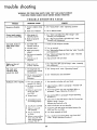
trouble shooting
WARNING:
FOR YOUR OWN SAFETY, TURN "'OFF" AND ALWAYS REMOVE
PLUG FROM POWER SOURCE OUTLET BEFORE TROUBLE SHOOTING
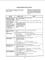
TROUBLE
TROUBLE
Excessive vibration
Cannot make square
cut when crosscutting
Cut binds, burns or
stalls motor when
ripping
Blade
not true
90 ° or 45 °
at
Tilt crank and
elevating hand
wheel turn hard
TABLE
PROBABLE CAUSE
REMEDY
1. Failure to tighten clamp
knob
1. See "Clamp
2. Blade out of balance
2. Use a different blade
1. Miter gauge not
adjusted properly
1. See "Check and Adjust the Miter Gauge"
"Assembly and Adjustments"
2. Blade not properly
aligned
2. See "Aligning Saw Blade with Table Top" under
"Assembly and Adjustments"
1. Dull blade with
improper tooth set
2. Warped board
1. Check set and sharpness of blade
2. True up material
3. Blade not properly
aligned
3. See "Aligning Saw Blade with Table Top" under "Assembly
and Adjustments"
4. Rip fence not properly
aligned
4. See "'Check and Adjust Rip Fence" under "Assembly
and Adjustments"
S. Spreader out of
alignment
5. Align spreader with saw blade
1. Stop screws not
properly
adjusted
1. See "Adjust
the 90 ° and 45 ° Stops"
and Adjustments"
1. Tilt clamp knob not
1.
See "Clamp
Knob" under "'Operating Controls"
Knob"
under "Operating
under
under
"Assembly
Controls"
loosened when making
tilt adjustment
2.
Kickbacks when ripping
SHOOTING
Dirt in worm and sector
gears-- and need of
lubrication
2. See "Maintenance
and Lubrication"
Use spreader and align with saw blade
1. Not using spreader or
spreader not aligned
1.
2. Rip fence not parallel
to blade
2. Adjust rip fence. (Refer to paragraph
Adjustments")
3. Failure to push wood
all the way past
saw blade
3. Push wood all the way past saw blade (Refer to
paragraph "Proper Operating Procedures")
4.
Warped wood
4. Use caution (Refer to paragraph
Procedures")
"Assembly and
"Proper Operating
5. Anti-kickback pawls
not working properly
S. Clean out any dust and apply a drop of oil around pin
Replace spring if broken
6. Cut-off piece confined
6. Allow cut-off piece to move laterally
7. Failure to use push
stick properly
7. Apply the push stick to the work piece between the
fence and the saw blade
g. Dull or ;rnproperly
set blade
8. Use sharp, properly set blade
9. Failure to use auxiliary
fence and push stick
when ripping material
narrower than 2"
9.
Sharpen pawl teeth with a file
22
See "'Auxiliary Fence/Push :Block" and "Push Stick"
under "'Proper Operating Procedures"
TROUBLE-SHOOTING
The following table lists some of
troubles
caused by low voltage,
suggested remedies:
TROUBLE
TABLE--MOTOR
NOTE: Motors used on wood-working tools
are particularly susceptible to the accumulation of sawdust and wood chips and should
be blown out or "'vacuumed" frequently to
prevent interference with normal motor
ventilation.
the most common
their causes and
REMEDY
PROBABLE CAUSE
1. Power line overloaded with
lights, appliances and other
motors.
1. Reduce line load.
2. Undersize wires or circuit too
long.
2. Increase wire sizes, or reduce length of wiring.
g. General overloading of power
company's facilities. (In many
sections of thecountry, demand
for electrical power exceeds
the capacity of existing
generating and distribution
systems.)
3. Request a voltage check from the power company.
Motor starts slowly or
fails to come up to full
speed.
1. Low Voltagerelay.
2. Starting relay
will not trip
1. Correct low voltage condition.
not operating.
2. Have relay replaced.
Motor
1. Motor overloaded.
1. Correct overload condition.
2. Improper cooling. (Air
circulation restricted through
motor clue to sawdust, etc.)
2. Clean out sawdust to provide normal air circulation
through motor.
1. Burned relay contacts (due to
extended hold-ln periods
caused by low line voltage,
etc.).
2. Open relay coil.
1. Have relay replaced.
3. Loose or broken connections
in motor terminal box.
3. Have wiring checked and repaired.
1. Starting relay not operating.
2. Voltage too low to permit
motor to reach operating
speed.
1. Have relay replaced.
3. Fuses or circuit breakers do
not have sufficient capacity.
3. Replace fuses or circuit breakers with proper
capacity units.
1. Motor overloaded.
2. Fuses or circuit
breakers
do
not have sufficient capacity.
1. Reduce motor load.
3. Starting relay not operating
(motor does not reach normal
speed).
3. Have relay replaced.
Motor fails to develop
full power. (Power output
of motor decreases rapidly
with decrease in voltage
at motor terminals.) For
example: a reduction of
10% in voltage causes a
reduction of 19% in
maximum power output of
which the motor iscapable,
while a reduction of 20%
in voltage causes a
reduction of 36% in maximum power output.
overheats.
Starting relay in motor
will not operate.
Motor stalls (resulting in
blown fuses or tripped
circuit breakers).
Frequent opening of
l_u_ or e;reu;t br_ak_r_:.
23
2. Have relay replaced.
2. Request voltage
_..
Replace
_uses
check from power company.
or
circuit
breakers.
PARTS LIST FOR CRAFTSMAN
12-INCH
DETAIL
A
MOTORIZED
FLOOR SAW
PARTS LIST FOR CRAFTSMAN
12-INCH MOTORIZED
MODEL NUMBER 113.299131
WHEN ORDERING
REPAIR
SHOWN ON THIS LIST:
PARTS,
1. THE PART NUMBER
2. THE PART NAME
ALWAYS
GIVE
THE
FLOOR SAW
FOLLOWING
INFORMATION
AS
3. THE MODEL NUMBER - 113.299131
4. THE NAME OF ITEM-12-1NCH
MOTORIZED
FLOOR SAW
Always order by Part Number - not by Key Number
FIGURE 1
Key
No.
1
2
3
4
5
6
7
8
9
10
11
12
13
14
15
16
17
18
19
20
21
22
23
24
25
26
Part
No.
62398
62325
62403
STD 501102
62473
144628
62474
62290
60122
62343
STD 541025
STD 551125
62011
60049
62081
62344
62083
STD 512520
37158
62120
STD 551237
454896
60127
STD 551143
30613
STD 600803
Description
Guard Assembly, Saw (See Fig. 3)
+Gauge Assembly, Miter (See Fig. 7)
Insert Assembly, Table (Includes
Key Nos. 4, 5, 6, 7)
*Screw, Set, 10-32 x 1/4", Hex.Soc.Cup Pt.
Insert, Table
*Screw, Type A No. 4 x 5/16", Flat Hd.
Clip, Insert
Fence Assembly, Rip (See Fig. 6)
*Screw, Set, 3/8 -16 x 15/16",Hex.Soc.Cup
Pt.
Table, Saw
*Nut, Hex., 1/4 -20x 7/16x 3/16"
* Lockwasher, 1/4"
Spacer, Fence Guide Bar
*Screw, Self Tapping,No. 4-40 x 3/16"
Tape, Fence
Bar, Fence Guide
Rack, Table
*Screw, Mach., 1/4-20 x 2",Rd.Hd.,Slotted
Ring, Retaining
Rod, Table Extension Slide
* Lockwasher, 3/8"
*Screw, 3/8 -16 x 1/2"',Hex.Hd.
*Bolt, 7/16-14 x l",Hex.Hd.
* Lockwasher, 7/16"
Clamp, Cord
*Screw, Type 23, No.8-32 x 3/8",Pan Hd.,Slotted
Key
No.
27
28
29
30
31
32
33
34
35
36
37
38
39
40
41
42
43
Pa_
No.
62216
STD 551131
STD 523107
62217
142745
STD 523112
62140
STD 541031
62141
62215
62402
60195
38845
62257
38746
38747
STD 51 0803
62461
62462
62463
62464
62465
Description
Extension Assembly, Table Sliding
* Lockwasher, 5/16"
*Screw, Mach., 5/16 -18 x 3/4",Hex.Hd.
Fence, Auxiliary
*Nut, Wing, 5/16 -18
*Screw, Mach.,5/16 -18 x 1-1/4",Hex.Hd.
Support, Extension Rod
*Nut, Hex., 5/16 -18 x 9/16 x 7/32"
Clamp, Table Extension
Support, Table Extension
Extension, Table
Screw, Flat Hex.Rec., 4-40 x 3/8"
Shoe, Cut Indicator
Housing, Cut Indicator
Washer, Spring
Plate, Cut Indicator
Screw, Mach., Pan Hd., 8-32 x 3/8"
Bag of Loose Parts (Legs)
(not illustrated)
Bag of Loose Parts (Aux. Fence)
(not illustrated)
Bag of Loose Parts (Saw)
(not illustrated)
Bag of Loose Parts (Extension)
(not illustrated)
Owners Manual (not illustrated)
*Standard Hardware Item - May be Purchased Locally.
+Stock Item - May be secured through the hardware departments of
most Sears or Simpsons-Sears Retail Stores or Catalog Order Houses.
PARTS LIST FOR CRAFTSMAN
12-INCH MOTORIZED
MODEL NUMBER 113.299131
FLOOR SAW
"0
3
2
Q
4
m
9
10
11
48
47
48A
49
5O
61 62
37
63
51A
51
64
65
56
Figure
2
55-
•
PARTS LIST FOR CRAFTSMAN
12-INCH MOTORIZED
MODEL NUMBER 113.299131
Key
No.
Part
No.
1
2
3
4
5
6
7
62459
30494
60177
6362
3540
63062
STD 600803
8
9
10
11
12
13
14
15
30613
62341
62342
62340
62339
STD 551131
STD 523106
STD 503705
16
17
18
62093
62330
STD 503103
19
20
62098
STD 601103
21
22
23
24
25
26
27
28
29
30
31
32
33
34
35
36
37
STD 551012
62100
STD 571812
62111
62218
STD 551050
62094
38825
62O97
62331
63011
62101
62099
62086
STD 571810
62090
STD 551125
Key
No.
Description
Motor Assembly (See Fig. 4)
Collar
+Blade, Saw, 12" Chisel Tooth
Nut, Saw Arbor
Wrench, Arbor
Wrench, Shaft
*Screw, Self-Tapping, No.8-32 x 3/8",
Pan Hd.
Clamp, Cord
Ring, Retaining, 3/4"
Washer, Plain, 25/32 x 1-3/8 x 1/8"
Pin, Motor Pivot
Support, Motor
* Lockwasher, 5/16"
*Screw, Mach., 5/16 -18 x 5/8"
*Screw, Set, 3/8 -16 x 5/8",
Hex.Soc. Flat Pt.
Screw, Stop
Cradle
*Screw, Set, 5/16 -18 x 3/8",
Hex.Soc. Cup Pt.
Trunnion, Back
*Screw, Mach., Type 23, 10-32 x 3/8",
Pan Hd.
*Washer, Plain, 7/32 x 1 x 1/16"
Bolt
Pin, Roll, 3/16 x 1-1/4"
Rod, Spreader
Bar, Spreader
*Washer, Flat, 17/32 x 1-1/16 x 3/32"
Screw, Lock
Ring, Retaining
Rod, Lock Screw Push
Knob Assembly, 2-1/4"
Washer, Knob Clamp
Spacer
Trunnion, Front
Collar
Pin, Roll, 3/16 x 1"
Plate, Bearing
* Lockwasher, 1/4"
*Standard
Hardware Item - May Be Purchased Locally.
+Stock I tern - May be secured through the hardware departments
Sears or Simpsons-Sears
Retail Stores or Catalog Order Houses.
of most
FLOOR SAW
Part
No.
38
STD 522506
39
40
41
42
43
44
62106
STD 511002
62091
62332
62333
STD 502503
45
46
47
48
48A
62356
62222
62219
62221
60159
49
50
51
51A
62223
STD 541031
62220
60160
52
53
54
55
62400
STD 541025
62401
STD 610802
56
57
58
59
60
61
62
63
64
65
66
67
68
62113
803835
118647
STD 522505
62460
62095
STD 522503
62096
37911
37837
30505
37836
60194
¢When replacing
_4JVhen replacing
Description
*Screw, Mach., 1/4 -20 x 5/8",
Hex. Hd.
Ind icator, Tilt
*Screw, Mach., No.10-24 x 1/4",Pan Hd.
Worm, Elevating
Knob Assembly, Pull
Crank Assembly
*Screw, Set, 1/4 -20 x 5/16",
Hex.Soc. Cup Pt.
Crank Assembly, Tilt
Shaft, Tilt
Ring, Retaining
$Gear
Washer, Spacing, 1-1/2 x .630 x .005
(Used to adjust end-play after installing
Key No. 48, supplied 5 in a package)
Worm, Tilt
*Nut, Hex., 5/16 -18 x 9/16" x 7/32"
SGear
Washer, Spacing, 1-1/2 x .875 x .005
(Used to adjust end-play after installing
Key No. 51, supplied 5 in a package)
Base, Saw
*Nut, Hex., 1/4 -20x 7/16 x 3/16"
Panel, Front
*Screw, Sheet Metal, No.8 x 5/16",
Type "B", Pan Hd.
Stiffener, Leg
Foot, Level ing
*Nut, Hex., 1/2-13 x 3/4 x 5/16"
*Screw,Mach., 1/4 -20 x 1/2"',Hex.Hd.
Leg, Base
Nut, Height Lock
*Screw, Mach., 1/4 -20 x 3/8",Hex.Hd.
Wrench, Lock
*Wrench, Hex-"L", 3/16"
*Wrench, Hex-"L", 5/32"
*Wrench, Hex-"L", 1/8"
*Wrench, Hex-"L", 3/32"
*Wrench, Hex-"L", 1/16"
gear (Key 48), use spacing washers (Key
gear (Key 51), use spacing washers (Key
48A)
51A)
to adjust end-play.
to adju st end-play.
repair
parts
PARTS LIST FOR CRAFTSMAN
12-INCH MOTORIZED
MODEL NUMBER 113.299131
4
2
FLOOR SAW
5
1
6
16
7
6
8
8
FIGURE 3 - 62398 GUARD
Key
No.
1
2
3
4
5
6
7
8
Part
No.
62398
60297
62391
62395
62389
62390
STD 551025
62136
62396
Key
No.
Description
9
10
11
12
13
14
15
16
17
Guard Assembly, Saw
Nut, Push
Pin, 1/4 x 1-1/2"
Support, Guard
Guard, Saw
Pin, 1/4 x 1-3/4"
*Washer, 17/64 x 5/8x 1/16"
Spacer, Pawl
Pawl
ASSEMBLY
Part
No.
STD 541025 *Nut, Hex, 1/4-20 x 7/16 x 3/16"
62210
Support, Splitter
26637
Handle, Lock
62399
Blade Assembly, Spreader
STD 522505 *Screw, Hex Ind. Hd., 1/4-20 x 1/2"
62392
Pin, 1/4 x 1"
STD 571810 i'Pin, Roll, 3/16x 15/16"
60004
Ring, Retaining, 1/4"
62134
Spring, Pawl
*Standard Hardware Item - May be Purchased Locally.
28
Description
PARTS LIST FOR CRAFTSMAN
12-INCH MOTORIZED
MODEL NUMBER 113.299131
1
FLOOR SAW
2
3
4
I
L
11
TO SWITCH
"to
12
•
MOTOR
\
I0
I
ANY ATTEMPT TO REPAIR THIS MOTOR MAY
CREATE A HAZARD UNLESS REPAIR IS DONE
BY QUALIFIED SERVICE TECHNICIAN.
REPAIR SERVICE
IS AVAILABLE
AT YOUR
NEAREST SEARS STORE.
15
8
SEE WIRING
Figure 4
FIGURE 4 - 62459 MOTOR
Key
No.
1
2
3
4
Pa_
No.
DIAGRAM,
PAGE 5
Figure 5
ASSEMBLY
FIGURE
Key
No,
Description
62459
• Complete Motor Assembly
62467
Box Assembly, Control (w/Nameplate)
STD 600603 *Screw, Self-Tapping, No.6-32 x 3/8",
Pan Hd., Slotted
STD 600803 *Screw, Self-Tapping, No.8-32 x 5/16",
Pan Hd., Slotted
633O9
Cover, Brake
1
2
3
4
5
5
6
7
8
9
10
11
12
13
14
15
*Standard Hardware Item -- May be Purchased Locally.
• Any attempt to repair this motor may create a Hazard unless
repair is done by qualified Service Technician.
Repair service is available at your nearest SearsStore.
5 - SWITCH ASSEMBLY
Part
No.
Description
62466
STD 601103
Bracket, Housing
Screw, Type 23, 10-32 x 3/8",
Pan Hd.
STD 551210
Lockwasher, External No. 10
STD 541110
Nut, Hex., 10-32 x 3/8 x 1/8"
60282
Box, Switch
60291"
• Box, Switch
60290
Washer, 3/4 x 1-1/16 x 1/64"
60287
Screw, Nylon, 6-32 x 5/16"
60256
Key
37838
Washer, 5/8 x 7/8 x 1/64"
37818
Relief, Strain
61086
Relief, Strain
62375
Cord with Plug
60267
Switch
63467
Cap, Insulator
STD 61 1005 Screw,Type B No.10 x 1/2"
*Standard Hardware Item - May be Purchased Locally.
=Canadian Model Only.
29
repair
parts
PARTS LIST FOR CRAFTSMAN
12-INCH MOTORIZED
MODEL NUMBER 113.299131
Figure
FLOOR SAW
6
•
FIGURE
Key
No.
1
Part
No.
62290
423350
2
3
62126
60049
4
5
6
7
62052
62051
62046
STD 511005
8
9
10
11
62291
62127
62130
62131
6-
62290 RIP FENCE ASSEMBLY
Key
No.
Description
Fence Assembly, Rip
*Screw, Mach., w/Ext. Tooth
Lockwasher, 3/8 -16 x 1/2",
Hex. Hd., Steel
Channel, Fence
*Screw, Tapping, No.4-40 x 3/16",
Pan Hd. Slotted
Retainer, Fence Index
Indicator, Fence
Shoe, Cam Face
*Screw, Mach., No.10-24 x 1/2",
Pan Hd. Slotted
Handle, Fence Lock
Head, Fence
Bushing, Fence Adjusting Shaft
Spring, Fence Adjusting Shaft
*Standard
I
Hardware
Item
Part
No.
12
60O67
13
14
15
16
17
18
19
20
21
22
23
24
25
26
62132
62049
62048
60230
30505
62129
62050
62047
62128
62055
62073
37837
60229
62053
- May be Purchased
3O
Description
*Screw, Set, 1/4 -20 x 1/4,
Socket Hd., Cup Pt.
Knob, Fence Adjusting
Spring, Squaring Pawl
Pawl, Fence
Screw, Set- Locking, 1/4-20 x 1"
*Wrench, Hex-"L", 1/8"
Shaft Assy., Fence Adjusting
Pin
Pin
Rod, Lock
Spring, Fence Lock
Lock, Fence
*Wrench, Hex-"L", 5/32"
Screw, Set-Locking, 5/16-18 x 1/2"
Support, Fence Lock
Locally.
PARTS LIST FOR CRAFTSMAN
12-INCH MOTORIZED
MODEL NUMBER 113.299131
14
FLOOR SAW
!
9
7
Figure 7
FIGURE
Key
No.
-1
2
3
4
5
6
7
Part
No.
7 -62325
MITER
Key
No.
Description
62325
tGauge Assembly, Miter
62068
Handle, Miter Gauge
STD 551031 *Washer, Plain, 21/64 x 1 x 1/16"
37893
Gauge, Miter
STD 600803 *Screw, Mach., No.8-32 x 5/16",
Pan Hd. Slotted
Indicator
135
37895
Block, Miter Gauge Indicator
37896
Pin, Miter Gauge Stop
*Standard
Hardware
GAUGE ASSEMBLY
Item
-
Part
No.
8
9417295
9
62230
10
11
12
13
STD 541231
62225
62383
60288
14
30505
May be Purchased
Description
*Screw, Mach., w/Lockwasher,
No.8-32 x 5/8", Pan Hd. Slotted
Rod Assembly,
Miter Gauge,
Consisting of Items 10,11,12
*Nut, Hex., 5/16-18 x 1/2 x 3/16"
Stud, Clamp
Stud, Pivot
Screw, Set, 1/4-20 x 3/8",
Self- Locklng
*Wrench,
Hex-"L",
1/8"
Locally.
tStock
Item -- Mav be secured through the Hardware
Departments
Sears or Sirnpsons-Sears
Retail Stores or Catalog Order Houses.
31
of most
How
to ORDER
Repair
Parts
Sears
The Model Number will be found on a plate attached rear of
base. Always mention the Model Number when requesting
service or repair parts for your 12-inch Motorized Floor Saw.
owners
manual
All parts
ROEBUCK
listed
AND
herein may be ordered
CO. or SIMPSONS-SEARS
through SEARS,
LIMITED.
When
ordering parts by mail, selling prices will be furnished on
request or parts will be shipped at prevailing prices and you will
be billed accordingly.
WHEN ORDERING
REPAIR
FOLLOWING
INFORMATION
PARTS, ALWAYS GIVE THE
AS SHOWN IN THIS LIST.
1. The PART NUMBER
2. The PART DESCRIPTION
MODEL NO.
3. The MODEL
NUMBER
113.299131
4. The NAME OF ITEM 12-INCH MOTORIZED
FLOOR SAW
113.299131
Sears
SER VICE
is at
YOUR
SERVICE
wherever YOU
live or move
in
Sears,
Your Sears merchandise
takes on added value when you
discover that Sears has over 2,000 Service Units through out the
country.
technicians
Each
is staffed
by Sears-trained,
professional
using Sears approved parts and methods.
the U.S.A.
Roebuck
Part No. 62465
and
Co.,
Chicago,
III. 60684
U.S.A.
Form No. SP4021-1
and
Simpsons-Sears
Limited,
Printed
Toronto
in U.S.A.
12/73