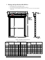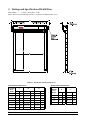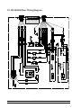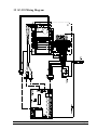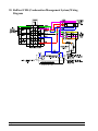
1
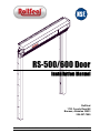
RS-500/600 Door Installation Manual RollSeal 1733 County Road 68 Bremen, Alabama 35033 256-287-7000 Part No. 4801-5166 Rev 01-2015 Owners Manual RS-500/600 Door Table of Contents 1 Warnings (Avertissements) .................................................................................................................................... 3 2 Limited Warranty ................................................................................................................................................... 8 3 Ratings and Specifications RS-500 Door ............................................................................................................... 9 4 Ratings and Specifications RS-600 Door ............................................................................................................. 10 5 Physical Description/Drawing.............................................................................................................................. 11 6 Use of Equipment ................................................................................................................................................. 11 7 Installation ............................................................................................................................................................ 12 7.1 Tools Required.......................................................................................................................................... 12 7.2 Overview .................................................................................................................................................. 12 7.3 Adjusting the Clear Opening .................................................................................................................... 12 7.4 Attachment Points of Door ....................................................................................................................... 13 7.5 Assembly of Parts ..................................................................................................................................... 14 7.6 Infrared Sensor Connectors ...................................................................................................................... 15 7.7 Fastening Door Assembly to Clear Opening ............................................................................................ 15 8 Electrical Connections for RS-500/600 Cooler Door ........................................................................................... 17 8.2 Connection of Controller to Head Unit. .................................................................................................... 17 8.3 Installing Prewired Switches .................................................................................................................... 17 8.4 Power Connection with Disconnect .......................................................................................................... 18 8.5 Preparation for Operation ......................................................................................................................... 18 9 Limit Switches ..................................................................................................................................................... 19 10 Door Features ....................................................................................................................................................... 19 10.1 Warning Indicator Light ........................................................................................................................... 19 10.2 Egress Strap (Optional Feature) ................................................................................................................ 19 10.3 Egress Buzzer (Optional Feature) ............................................................................................................. 19 11 Emergency Egress (Optional Feature) ................................................................................................................. 20 11.1 Installation ................................................................................................................................................ 20 11.2 Exiting (Opening) The Door ..................................................................................................................... 20 11.3 Resetting (Closing) The Door ................................................................................................................... 21 12 Egress Strap Removal/Re-Installation.................................................................................................................. 22 12.1 Removal .................................................................................................................................................... 22 12.2 Installation ................................................................................................................................................ 22 10. Press “Open” (and “Close” if required) a several times to insure proper operation. ............................................ 22 13 Manual Operation of Door ................................................................................................................................... 23 14 Adjustment of Brake ............................................................................................................................................ 24 15 Door Panel Adjustments ...................................................................................................................................... 25 16 Removal of existing Panel/Curtain Material ........................................................................................................ 26 17 Installation of Replacement Curtain ..................................................................................................................... 26 18 RS-500/600 Door Wiring Diagram ...................................................................................................................... 28 19 SC-325 Wiring Diagram ...................................................................................................................................... 29 20 RollSeal CMS (Condensation Management System) Wiring Diagram................................................................ 29 Please Retain This Manual for Future Reference Refer to SC-325 and SC-650 Controller Manual 4801-5156 and RS-500/600 Series Door Manual 4801-5154 for additional details. Page 2 RS-500/600 Door Part No 4801-5166 Rev 01-2015 1 Warnings (Avertissements) ! Warning! Disconnect All Power Sources Before Installing This Equipment. Failure To Disconnect Power Source Can Result In Property Damage, Serious Injury Or Death! !! Warning! Dangerous Rotating Machinery! Keep Hands, Clothing, Etc. Clear When Operating! Do Not Operate Without All Guards And Covers In Place! ! Warning! All Wiring Should Be In Accordance with National Electrical Codes Or Other Local Codes. !! Warning! The Installer Is Responsible For Complying With All Relevant Regulations, Such As National Wiring Regulations And Accident Prevention Regulations. Particular Attention Must Be Given To The Cross-sectional Areas Of Conductors, The Selection Of Fuses Or Other Protection, And Protective Earth/Ground Connections! !! Warning! The Voltages In The Power Cables And Certain Parts Of The Drive Can Result In Death. Whenever The Drive Has Been Used, It Must Be Isolated And Disconnected For 5 Minutes Before Any Work Commences. Part No 4801-5166 Rev 01-2015 RS-500/600 Door Page 3 ! Danger! Only Qualified Electrical Personnel Familiar With The Construction And Operation Of This Equipment And The Hazards Involved Should Install, Adjust, And/Or Service This Equipment. Read And Understand This Manual In Its Entirety Before Proceeding. Failure To Observe This Precaution Could Result In Severe Bodily Injury Or Death! ! Warning! Item 4501-6312 (Warning Moving Door Label) Supplied With Door, MUST Be Installed On Inside Of Cooler/Freezer Beside Door Opening. IMPORTANT INSTALLATION INSTRUCTIONS !! Warning! To Reduce The Risk Of Severe Injury Or Death: 1. READ AND FOLLOW ALL INSTALLATION INSTRUCTIONS. 2. Do not connect the door operator to the source of power until instructed to do so. 3. Locate the control station: (a) within sight of the door, (b) at a minimum height of 5 feet so small children cannot reach it, and (c) away from all moving parts of the door. Remove all ropes and remove or make inoperative all locks connected to the garage door before installing opener. 4. For products having a manual release, instruct the end user on the operation of the manual release. Where possible, install the door opener 7 feet or more above the floor. For products having an emergency release, mount the emergency release within reach, but at least 6 feet above the floor and avoiding contact with vehicles to avoid accidental release. Page 4 RS-500/600 Door Part No 4801-5166 Rev 01-2015 IMPORTANT SAFETY INSTRUCTIONS ! ! Warning! To Reduce The Risk Of Severe Injury Or Death: 1. 2. READ AND FOLLOW ALL INSTRUCTIONS! Never let children operate or play with door controls. Keep the remote control (where provided) away from children. 3. Personnel should keep away from a door in motion and keep the moving door in sight until it is completely closed or opened. NO ONE SHOULD CROSS THE PATH OF A MOVING DOOR. 4. Test the door’s safety features at least once a month. After adjusting either the speed or the limit of travel, retest the door operator’s safety features. Failure to adjust the operator properly may cause severe injury or death. NEVER GO UNDER A STOPPED, PARTIALLY OPEN DOOR. 5. For products having a manual release, if possible, use the manual release only when the door is closed. Use caution when using this release when the door is open. 6. KEEP DOORS PROPERLY OPERATING AND BALANCED. See Door Manufacturer’s Owner’s Manual. An improperly operating or balanced door can cause severe injury or death. Have trained door systems technician make repairs to cables, spring assemblies, and other hardware. 7. Install the Entrapment Warning label next to the control button in a prominent location. Install the Emergency Release Marking. Attach the marking on or next to the emergency release. 8. After installing the opener, the door must reverse when it contacts a 1-1/2 inch high object (or a 2 x 4 board laid flat) on the floor. 9. SAVE THESE INSTRUCTIONS. French Translated Warnings ! Avertissement! Disjoindre fournissent de l'énergie tout les sources avant qu'installer cet équipement. F|ailure| à disjoindre la source de pouvoir peut résulter dans dommage de propriété, blessure sérieuse ou mort ! ! Avertissement! Mécanisme tournant dangereux ! Garder les mains, vêtissant, etcC|lear| quand fonctionner ! Ne fonctionnez pas sans toutes gardes et couvertures dans lieu ! ! Avertissement! Tout montage sur fil de fer doit être selon codes électriques nationaux ou autres indicatifs régionaux. Part No 4801-5166 Rev 01-2015 RS-500/600 Door Page 5 ! Avertissement! L'Installer est responsable pour conformer avec tout règlement pertinent, telles que règlement et règlement de prévention d'accident de montage sur fil de fer nationaux. Pl'attention articulaire doit être donnée pour les aires sectionnelles transversales de conducteurs, le choix d'elles fusées ou autre protection, et terre / prises de terre protecteur ! ! Avertissement! Les tensions dans le pouvoir câblent et certains parties de la promenade en voiture peuvent résulter dans la mort. Wle |henever| la promenade en voiture a été utilisé il doit être isolé et détaché pendant 5 procès avant que tout travail commence. ! Danger ! Seulement familier électrique de personnel qualifié avec la construction et opération de cet équipement et les hasards ont enveloppé devoir installer, arranger, et/ou - la révision cet équipement. R|ead| et comprendre ce manuel en entier avant que procéder. F|ailure| à observer cette précaution peut résulter dans dommage corporel sévère ou mort ! ! Avertissement ! Point 4501-6312 (Avertissement Moving étiquette de porte) Livré avec porte, doit être installé à l'intérieur du réfrigérateur / congélateur côté Ouverture de la porte. Page 6 RS-500/600 Door Part No 4801-5166 Rev 01-2015 LES INSTRUCTIONS D'INSTALLATION IMPORTANTES ! AVERTISSEMENT! À réduire le risque de blessure sévère ou mort: 1. LU ET SUIVENT TOUTES INSTRUCTIONS D'INSTALLATION. 2. Ne liez pas l'opérateur de porte per la source de pouvoir jusqu'à instruit faire ainsi. 3. Localisez la station de commande: (a) en vue de la porte, (b) à un minimum la hauteur de 5 pieds ainsi petit enfants ne peuvent pas l'atteindre, et (c) loin de tous parties en mouvement de la porte. 4. Pour produits ayant un délivrance manuelle, instruire l'utilisateur final sur l'opération de la délivrance manuelle. RÈGLEMENTS DE SÉCURITÉ IMPORTANTS ! AVERTISSEMENT! À réduire le risque de blessure sévère ou mort: 1. LU ET SUIVENT TOUTES INSTRUCTIONS! 2. Jamais laisser fonctionner enfants ou mouvoir vivement avec les autorités de porte. Gardez la télécommande (où a fourni) loin des enfants. 3. Le personnel devrait garder loin une porte dans mouvement et subsistance la porte en mouvement dans vue jusqu'à est complètement fermé ou avoir ouvert. CES AUCUNS DOIVENT CROISER LE CHEMIN D'UNE PORTE EN MOUVEMENT. 4. Éprouvez les traits de sécurité de la porte au moins une fois par mois. Après qu'arrangeant la vitesse ou la fin de course, retest les traits de sécurité de l'opérateur de porte. Manque à arranger l'opérateur correctement peut causer blessure sévère ou mort. 5. Pour produits ai manuel la délivrance, si possible, utiliser la délivrance manuelle seulement quand la porte est fermée. Précaution d'utilisation à utiliser cette délivrance quand la porte est ouverte. 6. GARDER LES PORTES CORRECTEMENT QUI OPÈRE ET ÉQUILIBRÉ. Voir la porte fabricant propriétaire manuel. Un improprement qui opère ou balancé porte peut causer blessure sévère ou mort. Formez les technicien de systèmes de porte faitez les réparations per les câbles, réunions de source, et autre quincaillerie. 7. SAUVEZ CES INSTRUCTIONS. Part No 4801-5166 Rev 01-2015 RS-500/600 Door Page 7 2 Limited Warranty All products are warranted to be free from defects in material and workmanship for a period of one (1) year or 100,000 cycles, whichever occurs first, from the date of purchase if installed and used in strict accordance with the installation instructions. Liability is limited to the sale price of any products proved to be defective or, at manufacturers’ option, to the replacement of such products upon their return. No products are to be returned to the manufacturer, until there is an inspection and/or a return-goods authorization (RGA) number is issued. All complaints should be directed first to the authorized distributor who sold the product. If satisfaction is not obtained or the name of the distributor is not known, write the manufacturer that appears below, directed to the attention of Customer Service Manager. This limited warranty is expressly in lieu of any and all representations and warranties expressed or implied, including any implied warranty of merchantability or fitness for a particular purpose. The remedy set forth in this limited warranty shall be the exclusive remedy available to any person. No person has authority to bind the manufacturer to any representation or warranty other than this limited warranty. The manufacturer shall not be liable for any consequential damages resulting from the use of our products or caused by any defect, failure or malfunction of our products. (Some areas do not allow the exclusion or limitation of incidental or consequential damages, so the above limitation or exclusion may not apply to you.) This warranty gives you specific legal rights and you may also have other rights that vary from area to area. Warrantor: RollSeal 1733 County Road 68 Bremen, Al 35055 256-287-7000 Page 8 RS-500/600 Door Part No 4801-5166 Rev 01-2015 3 Ratings and Specifications RS-500 Door Motor Ratings: 230 VAC, Three Phase, 1/4 HP Door approved by the NSF (National Sanitation Foundation) Motor must be connected through Controller SC-325. See SC-325 and SC-650 Controller Manual (4801-5156). TABLE 1 RS-500 Door Standard Dimensions: WIDTH Related Dimensions HEIGHT Related Dimensions RS-500 Door Width Ft In cm Ft In cm Ft In cm 4'(W) 4 0 122 6 5-1/2 197 6 8-15/16 206 5'(W) 5 0 153 7 5-1/2 227 7 8-15/16 236 6'(W) 6 0 183 8 5-1/2 258 8 8-15/16 267 6'6"(W) 6 6 198 8 11-1/2 273 9 2-15/16 7'(W) 7 0 214 9 5-1/2 288 9 8'(W) 8 0 244 10 5-1/2 319 10 10'(W) 10 0 305 12 5-1/2 380 11'(W) 11 0 335 13 5-1/2 12'(W) 12 0 366 14 5-1/2 A D Part No 4801-5166 Rev 01-2015 E RS-500 Door Height B C Ft In cm Ft In cm 7'(H) 7 0 214 8 8-11/16 266 7'6"(H) 7 6 229 9 2-11/16 281 8'(H) 8 0 244 9 8-11/16 296 282 9'(H) 9 0 275 10 8-11/16 327 8-15/16 297 10'(H) 10 0 305 11 8-11/16 357 8-15/16 328 11'(H) 11 0 335 12 8-11/16 387 12 8-15/16 388 12'(H) 12 0 366 13 8-11/16 418 410 13 8-15/16 419 441 14 8-15/16 449 RS-500/600 Door Page 9 4 Ratings and Specifications RS-600 Door Motor Rating………..230 VAC, Three Phase, 1/2 hp Motor must be connected through controller. See RS SC-650 Manual (4801-5156). TABLE 2 RS-600 Door Standard Dimensions: WIDTH Related Dimensions HEIGHT Related Dimensions RS-600 Door Width In. cm In. cm In. cm 4'(W) 48 122 64-13/32 164 80-15/16 206 5'(W) 60 153 76-13/32 194 92-15/16 6'(W) 72 183 88-13/32 225 7'(W) 84 214 100-13/32 255 A D E RS-600 Door Height In. cm In. cm 236 7'(H) 84 214 92-11/16 266 104-15/16 267 8'(H) 96 244 104-11/16 296 116-15/16 297 9'(H) 108 275 128-11/16 327 10'(H) 120 305 140-11/16 357 8'(W) 96 244 112-13/32 286 128-15/16 328 9'(W) 108 274 124-13/32 316 140-15/16 358 120 305 136-13/32 347 152-15/16 388 10'(W) Page 10 RS-500/600 Door B C Part No 4801-5166 Rev 01-2015 5 Physical Description/Drawing Installation of a RollSeal RS-500/600 Automatic Door involves, at a minimum, connecting to the Smart Controller that connects to the AC power, the door motor, the Up/Down button, and the safety beam. Other accessories can be added such as a remote IR sensor, remote radio link, and door movement indicators such as lights and bells. 6 Use of Equipment The RollSeal RS-500/600 Door is an automatic motorized curtain enclosure for a doorway. Part No 4801-5166 Rev 01-2015 RS-500/600 Door Page 11 7 Installation 7.1 Tools Required 3/8 in. (10 mm) Power screwdriver (portable) 3/16 in. (5 mm) Drill bit and power drill 3/8 x 1 in. Bolts and nuts (supplied) Socket Hammer Tape measure Carpenter's level NOTE: Other Tools May Be Required According To Installation. 7.2 Overview The RS-500/600 Door is shipped with pre-assembled vertical members (left track and right track), and a preassembled horizontal member (head unit). When components are received, check for damaged, loose or missing parts. If there are damaged or missing parts contact your RollSeal distributor immediately. Please read and understand all instructions in this manual before beginning installation. 7.3 Adjusting the Clear Opening Locate your particular system in Table 1 or Table 2, Pages 9-10. Read the value of height and width of the clear opening for the door size that you are installing. This gives the required dimensions of the clear opening. If necessary, adjust the dimensions of the mounting posts or framing members to the height and width of your RS-500/600 Door System as shown in Diagram 7A. Refer to Section 7.4 (Page 13, Diagram 7B) for details of attaching door to framing members. Framing material must provide suitable support for attachment of screws. Make sure that mounting posts or framing members are positioned so that the screw holes of the outer flanges of the vertical members will align with the mounting posts or framing (Section 7.4, Page 13, Diagram 7B). Make sure that there is room for the motor and control box without encountering any obstructions. NOTE: Allow 1' (30.4 cm) minimum, preferably 18" (45.7 cm) clearance above the Head Unit for future panel maintenance or replacement. Page 12 RS-500/600 Door Part No 4801-5166 Rev 01-2015 7.4 Attachment Points of Door When sizing the clear opening for attachment of the door, pay close attention to the following guidelines. Door flanges have pre-drilled holes that serve as mounting points of door. Flange widths are shown in Diagram 7B. 1. Make sure that door assembly is plumb and square. 2. The top unit has a top flange and a bottom flange. Make sure these flanges overlap framing. 3. The vertical members have inner flanges and outer flanges. The outer flanges have pre-drilled holes that serve as attachment points. Make sure the outer flanges overlap framing. 4. When door is raised in front of clear opening (Section 7.7, Page 15), flanges must be flush against framing for attachment of screws. Bottom View Framing Members Part No 4801-5166 Rev 01-2015 RS-500/600 Door Page 13 7.5 Assembly of Parts Arrange the horizontal member, left vertical member (left track), and right vertical member (right track) on the floor in front of the clear opening as shown in Diagram 7C. The curtain side of the horizontal member and each vertical member faces down. A End of horizontal member B U-shaped plate On each end of the horizontal member is a U-shaped plate that fits inside each vertical member. The U-shaped plate has four bolt holes, two on the inside and two on the outside flanges that match bolt holes in the vertical member. See Diagram 7C. 1. Align the vertical member with the U-shaped metal plate at end of horizontal member. 2. Slide the vertical member onto the outside of the Ushaped metal plate of the horizontal member as shown in A. 3. Insert bolts through bolt holes as shown in B. Install nuts. Tighten bolts & nuts securely. 3/8" x 1" Bolts & nuts Plate fits inside vertical member Slide vertical member over U-shaped plate. Vertical Member Clear Opening At this end of members Placement of Parts for Assembly Lay left track, right track, and horizontal member face down in front of the clear opening as shown. Page 14 RS-500/600 Door Part No 4801-5166 Rev 01-2015 7.6 Infrared Sensor Connectors Located at the bottom of each vertical member is an infrared detector. The detector on each vertical member operates as a safety device if the infrared beam is interrupted. Door can be set to stop if beams are broken while closing, or to stop and reverse to the full open position. Refer to the RollSeal SC-325 and SC-650 Controller Manual for more information. 1. Locate female connector on vertical member. This connector is attached to the infrared detector. 2. Locate male connector on horizontal member. Unroll cable until connectors meet. Pull enough slack for photo-eye replacement and troubleshooting purposes. 3. Plug connectors together. Make sure connectors interlock. 4. Repeat for both infrared detectors. 5. Cable ties and adhesive mounts are supplied to secure wire to the inside of tracks. NOTE: For each vertical member, unroll respective sensor cable attached to horizontal member until cable reaches the connector attached to the vertical member. Plug connectors together. Some slack must be left at photo eyes for replacement purposes. 7.7 Fastening Door Assembly to Clear Opening 1. Use a tape measure and make sure that the overall height and overall width of the clear opening meet the requirements: Overall Height = Height + 20.688 in. (52.55 cm), Overall Width = Width + 16.4 in. (41.66 cm). Reference Table 1 or 2, Pages 9-10 and Diagram 7A, Page 12. 2. Make sure that door assembly is plumb and square. See Diagram 7E. Part No 4801-5166 Rev 01-2015 RS-500/600 Door Page 15 3. Center door assembly on clear opening. Align the bottom of each vertical member with the respective framing board or posts of the clear opening. Note: The vertical members should be aligned so that their outer flanges will exactly overlap with the framing boards or posts when the door assembly is raised into position. 4. Assemble workers and each side of the door assembly. See Diagram 7F. Important: Slowly Lift Top Of Door Assembly To Raise The Door. 5. 6. 7. Lean door assembly upright against clear opening. Carefully press flanges of the door assembly flush against faces of framing boards or posts. Fasten Tek screws (in steel) or lag screws (in wood) through the flanges on sides of door assembly. Securely tighten all screws. 8. On the lower and upper flanges of the horizontal member there are attachment points for fastening screws. Fasten Tek screws (in steel) or lag screws (in wood) through the holes. This secures the top of the door to the clear opening. 9. Locate the two floor mounting holes at the bottom of the left & right tracks. See Diagram 7G. 10. Drill a 1/4" hole and install Hammer Set Anchors (1002-6030) in both right and left tracks. See Diagram 7G. 11. This completes fastening of the door assembly to the clear opening. Page 16 RS-500/600 Door Part No 4801-5166 Rev 01-2015 8 Electrical Connections for RS-500/600 Cooler Door The Cooler Setup is designed to enable door installers to completely install and test door operation. Electrician is still required to connect power to door, but all switch and interface connections are made to be pluggable for ease of installation. 8.2 Connection of Controller to Head Unit. 1. Mount controller at desired location within 3’ of junction box on Head Unit. 2. Controller has and AC and DC harness prewired that connects to head unit as shown in Diagram 8A. 8.3 Installing Prewired Switches Cooler Switches are prewired with a CPC quick connect. You have two switch assemblies an Outside Cooler with harness out the top that is 6’ long and an Inside Cooler with harness out the bottom that is 1.5’ long. 1. Connect Outside switch to Controller with CPC connection. Push and turn CPC connector until it’s completely locked in place. 2. Mount Outside Switch in desired location on cooler wall. Note: Cover removed for mounting. 3. Drill 1” hole through Cooler Wall to run Inside Switch out to connect to Outside Switch. 4. Route Inside Switch Harness through hole and connect to bottom of Outside Switch with CPC. 5. Mount Inside Switch in desired location. Note: Cover removed for mounting. 6. Install Conduit Straps on conduit as required. Mount a strap close to CPC connection to prevent tampering. Insure conduit is run in a way to prevent moisture from running into electrical units. 7. Seal hole Part No 4801-5166 Rev 01-2015 RS-500/600 Door Page 17 8.4 Power Connection with Disconnect 1. 2. 3. 4. 5. 6. 7. Mount Disconnect in desired location. Connect harness from Disconnect to Control with CPC. Push and turn to lock in place. Remove Disconnect cover. Switch must be in off position to remove cover. Connect conduit and electrical supply to Disconnect. Connect 115V power supply to Disconnect as shown in Diagram 8C. Place cover back on Disconnect. Add conduit straps to conduit. 8.5 Preparation for Operation Refer of the RollSeal SC-325 and SC-650 Controller Manual (4801-5156) for more information on Controller Settings. Note: If you detect any problems, STOP. Disconnect electrical power. Contact your distributor for assistance. 1. 2. 3. Insert fuse in Control. Apply 115VAC power to Control and turn Control toggle switch on. Set the Open and Close Limits: 1. Depress the Mode button (●) for at least 5 seconds. P1 (Close Time Delay) will be then be displayed in the Display Indicator. 2. Depress and release the Mode button until PS1 (Change Program Limits) is displayed. 3. Depress Up ( ) until “yes” is displayed. 4. Depress the Mode button again (●). PS2 (Set Open Limit) will be displayed. 5. The door will proceed to the open limit and then stop. Once the door stops, adjust open limit using the Up ( ) or Down ( ) buttons until open limit is satisfactory. 6. Depress the Mode button (●) again. PS3 (Set Closed Limit) will be displayed. 7. The door will proceed to the closed limit and then stop. Once door stops, adjust this limit using the Up ( ) or Down ( ) buttons until the close limit is satisfactory. 8. Depress the Mode button (●) again and the controller will exit the programming mode and return to displaying the actual position. 4. Press “Open” button on Outside Switch. If the Door is set to automatically close, door will time out and automatically close if safety beams are clear. If the Door is set to manually close, press “Close” button on Outside Switch and door should close. 5. Press “Open” (and “Close” if required) a couple times to insure proper operation. 6. Repeat steps 4 and 5 for Inside Switch. 7. Verify Safety Beams reverse door when blocked during closing. 8. Verify Leading Edge Switch is operational. 9. Verify that Warning Light and Egress Buzzer (if applicable) are functioning properly. 10. Ensure Safety Pull Hook for Egress is mounted inside cooler and Manual Crank Handle for motor is mounted outside. The door is now ready for operation. Page 18 RS-500/600 Door Part No 4801-5166 Rev 01-2015 9 Limit Switches The controller keeps track of the "open" and "closed" positions of the door by means of a mechanical encoder wheel that is located in the control box. The controller electronically counts steps as the wheel turns to keep track of the door position. There are three limit switches located within the horizontal member mechanism. See Diagram 9A. These switches are attached to levers that contact the curtain. The Home Switch establishes the 'open' reference position of the door curtain. This creates the zero reference position, from which the encoder counts the position of the door. The Safety Switch is a fail-safe switch that stops the curtain in the unlikely event of malfunction of the home switch. The Leading Edge Switch is a switch that stops the curtain in the event of a doorway obstruction. 10 Door Features 10.1 Warning Indicator Light (Optional Feature) Any time the cooler door is opening or closing, this light will flash indicating movement of door. Note: On the SC-325 and SC-650, P4 setting in program mode must be set to 0 for proper operation. Note: This feature will not work on Interlock or Freezers using CMS unit. 10.2 Egress Strap (Optional Feature) The Emergency Egress feature provides a simple and convenient way to open door in emergency situation from inside the cooler should the door motor become inoperative due to a power failure or other conditions. The Emergency Egress Strap is located at center top of door. The door is opened by using the Emergency Egress Tool to hook D-Ring and pull strap down. Strap may be pulled by hand also. As strap is pulled, the door will open up enough that person can exit cooler safely. 10.3 Egress Buzzer (Optional Feature) In the event the Egress Strap has been pulled, a buzzer will sound from the Head Unit as long as door has power. To turn buzzer off, the egress strap must be fully reset. See Section 11.3 for information on re-setting the Egress Strap. Part No 4801-5166 Rev 01-2015 RS-500/600 Door Page 19 11 Emergency Egress (Optional Feature) The Emergency Egress feature provides a simple and convenient means of exiting a RollSeal RS-500/600 Door from the inside of the structure should the door motor become inoperative due to a power failure or other conditions. 11.1 Installation Install the two Strap Retainers (1040-8400) to the left or right side outside of door jamb as shown below. For a wood framed door jambs use two #10 x1 screws (1004-1386). For a metal framed door jamb use two #8x1/2 Tek screws (1004-2492). See Diagram 11A. Diagram 11A Diagram 11B 11.2 Exiting (Opening) The Door Page 20 1. Remove Emergency Egress Tool from the retainers on the side of the door. 2. Connect the hook end of the tool to the D-Ring on the top of the door frame. See Diagram 11B. 3. Pull down on the Egress Strap. The Door will raise approximately half way up. The door will open enough for a person to exit the structure. See Diagram 11C. RS-500/600 Door Part No 4801-5166 Rev 01-2015 11.3 Resetting (Closing) The Door After the RollSeal RS-500/600 Door is opened by using the Emergency Egress Strap, the door must be carefully re-set to ensure proper operation in the future. ! CAUTION! When the Cam Buckle is released, the door will rapidly close unless tension is held on the strap. Keep fingers away from buckle while closing. 1. Firmly hold strap. See Diagram 11D. 2. Press the Cam Buckle Release. See Diagram 11E. 3. Gradually feed strap through Cam Buckle until door is closed at bottom. 4. Return Emergency Egress Tool to retainers for future use. 5. Cycle the door up and down in normal operating mode to ensure proper re-setting of the door. Adjust if necessary. Door should now function normally. Diagram 11D Diagram 11E Part No 4801-5166 Rev 01-2015 RS-500/600 Door Page 21 12 Egress Strap Removal/Re-Installation 12.1 Removal 1. 2. 3. Locate the door controller and turn off the power switch on the left side of the controller. Remove the door’s head unit cover. Place the door in the JOG mode by holding the Up and down arrows on the controller at the same time until you see “JOG” in the controller’s display. ! Warning! Watch the panel closely while you are slowly jogging/rolling the curtain up on the drive shaft. Stop when you see the area where the long egress strap is connected to the short egress piece attached to a triangle panel. This should bring the strap and connection point, right to the top for easy access. Failure to stop can cause curtain to reverse direction and damage door components. 4. 5. Find the area where 2 loops are attached with a quick-link, unscrew the quick-link that attaches the long yellow strap loop to the yellow loop of the triangle piece. Make sure not to drop the weight into the door. Access the inside area of the cooler/freezer box through the door opening. If the strap is hanging inside, unhook and remove the gold buckle and the damaged yellow strap (top center of door) from the door. 12.2 Installation 1. Locate the door controller and turn off the power switch on the left side of the controller. 2. Remove the door head unit cover. 3. Un-roll the yellow egress strap with attached gold buckle. NOTE: Insert the strap through the hole in the center of the door, near the top, where original strap was traveling down inside the curtain and replace the old gold buckle with the new one. 4. Proceed to the outside area and locate the roller assembly at the top center of the door where the original strap came into the curtain area from the inside cooler/freezer area. Use anything with some stiffness (banding material) and feed the stiff item through the roller and down through the slot located in the inside cooler/freezer area and tape or tie it to the small loop (not the D-ring) of the yellow strap. Then gently pull it through the hole and roller assembly at the top/center of the door. 5. Ensure the yellow strap is not twisted. Place the counter weight onto the yellow strap. 6. Attach the new strap (small loop) that you just pulled into the curtain area to the (small loop) strap on the triangle piece of panel using the quick-link. 7. Attach the gold buckle to the door frame. 8. With the controller still in JOG mode, use the down arrow to lower the door to the floor. Exit JOG mode by holding the Up and Down arrows on the controller at the same time until you see “---” in the display of the controller. 9. Press “Open” button. If the Door is set to automatically close, door will time out and automatically close if safety beams are clear. If the Door is set to manually close, press “Close” button and door should close. Note: If you detect any problems, STOP. Disconnect electrical power. Contact your distributor for assistance. 10. Press “Open” (and “Close” if required) a several times to insure proper operation. 11. Re-attach the cover. Page 22 RS-500/600 Door Part No 4801-5166 Rev 01-2015 13 Manual Operation of Door Operating Instructions The RS-500/600 Door can be operated manually in the event of a power outage or if there is a motor malfunction. To operate the door manually, perform the following instructions. ! Warning! Disconnect All Electrical Power To Motor Before Attempting To Operate The Door Manually! ! Warning! The Curtain Is Released When Brake Lever Is Disengaged. Do Not Disengage Brake Until Door Opening Is Clear! If door is OPEN (door curtain raised) perform the following steps: 1. 2. Locate brake lever at bottom of motor. (See diagram below). Carefully release brake by flipping lever down. CAUTION: Curtain will drop when brake is released. If door is CLOSED (door curtain lowered) perform the following steps: 1. 2. 3. 4. Locate brake lever at bottom of motor. Carefully release brake by flipping lever down. Motor shaft is accessible from bottom of motor. Use provided Crank Handle to rotate motor shaft. Carefully turn motor shaft counterclockwise to raise door curtain. NOTE: The drive (as viewed from the 'motor end' of door) is synchronized with clockwise or counterclockwise rotation of the motor shaft. 5. When door curtain has been raised to desired height, flip brake lever up to engage brake. Part No 4801-5166 Rev 01-2015 RS-500/600 Door Page 23 14 Adjustment of Brake After extended operation of the brake lever, the brake may become worn. As the brake wears, some adjustment to the brake is required. Lettered diagrams below correspond to lettered instructions. Follow instructions to adjust brake: 1. Close door curtain to fully lowered position. 2. Engage Brake lever. 3. Disconnect electrical power to motor. 4. Remove four Phillips screws (A). 5. Remove cover (B). 6. Straighten the bent tab (C) of spider nut. . Page 24 7. Tighten spider nut (C) snuggly against blower wheel. Make sure a tab of spider nut is aligned with a notch in the shaft 8. Bend tab (C) upward into notch of shaft. 9. Replace cover (B). 10. Replace four Phillips screws (A). 11. Disengage brake lever (D). 12. Adjustment complete RS-500/600 Door Part No 4801-5166 Rev 01-2015 15 Door Panel Adjustments During normal operation, the tension pipes should run in close proximity of each other. See Diagram 15A. The clearance between the tension pipes should normally be between 1/4 to 1/2 (6.35 mm - 12.7 mm). There are two situations pertaining to the tension pipes that may cause problems with door operation. If the tension pipes are too far apart, the tension pipes will not repel each other. This causes poor contact between the floating magnets and laminated steel. On the other hand, if the tension pipes are riding one another (i.e. touching one another), the door panel material does not flow evenly, thus leaving wrinkles in the panel instead of a stretched, smooth & even appearance. Adjustment Procedures The clearance between the tension pipes can be adjusted by raising or lowering the door panels. Each door has three panels: (1) The inside panel (panel facing the inside of building) is attached to the back plate. (2) The center panel is attached to the roller. (3) The outside panel (facing the outside of building) is attached to the front bar. Adjustments are made to the inside panel and/or the outside panel. To adjust the height of the outside tension pipe, raise or lower the outside door panel by detaching the panel hook & loop from the front bar, and raising or lowering the panel. Then re-attach the panel loop to the hook on the front bar. Be sure to keep tension pipe level during this procedure. To adjust the height of the inside tension pipe, raise or lower the inside door panel by detaching the panel hook & loop from the back plate, and raising or lowering panel. Then re-attach the panel loop to the hook on back plate. Be sure to keep tension pipe level during this procedure. Install Tek screws through the panel material and into the back plate to securely hold the material in place. Part No 4801-5166 Rev 01-2015 RS-500/600 Door Page 25 16 Removal of existing Panel/Curtain Material ! Warning! The Curtain Is Released When Brake Lever Is Disengaged. Do Not Disengage Brake Until Door Opening Is Clear! 1. 2. Locate the door controller and turn off the power switch on the left side of the controller. Locate the brake on the motor. It resembles a paint bucket handle that has been pushed upon a clip. Pull the brake release handle down towards the floor. This will allow the panel to go to the floor. NOTE: You may have to assist by rolling the panel downward. 3. 4. 5. 6. Remove the Head Unit Cover and lower to the floor. Locate the 3 fabric sheets that make up the entire door curtain. See Diagram 15B, Page 25. The center panel has a hook & loop strip across the top. The center panel does not have magnets or hook & loop strips on the sides. The inside and outside panels have hook & loop strips at the top, and magnets or hook & loop strips along the sides of the panels. The outside panel may be identified as the longer of the two panels. Mark the end of each sheet and along the edge of each sheet with a marker. This will prove vital to ensure you install the new panel sheets at the proper locations to alleviate major curtain adjustment. Remove the 3 screws from each sheet (front, center, and back). See Diagram 15B, Page 25. Detach the hook & loop area of each sheet left to right, starting with front, then center, and then back sheets. Let the panel/curtain fall to the floor. NOTE: If the door is equipped with an egress assembly you will see the yellow egress strap attached to a triangle piece of material with a quick-link connector. If it does not have this strap, read the notes below and proceed to next step 8. 7. Un-screw the quick-link connector and allow the panel to hit the floor. NOTE: Observe how the tension pipes are installed before removal. They MUST be reinstalled first, with one pipe in the front/outer pocket (closest to outside of the cooler) and the other pipe in the back/inside pocket. Locate the back pipe behind the triangle piece that is attached to the yellow strap. The front/outer pipe will always hang lower than the back/inside pipe. NOTE: Failure to install properly could result in door sticking up. 8. Slide the 2 tension pipes out of their respective pockets. Remove the panel/curtain away from the door. You are now ready to install the new panel/curtain. 17 Installation of Replacement Curtain 1. Place the new panel in front of the door opening and make sure the part number label is on the left side. NOTE: If door is equipped with egress system yellow strap ensure that the strap is positioned to the front side of the back/inside panel to allow connection to the triangle piece of material with the quick-link connector. 2. 3. 4. Take the back/inside curtain (Diagram 17A, Detail 1 and Detail 2) and attach the material to the backplate placing material on the marks that were created during removal of old panel. After the inside curtain has been attached, attach the egress strap (if equipped) to the triangle piece of material with the quick link connector. Take the outside curtain (Diagram 17A, Detail 1 and Detail 2) and attach to the top bar. Page 26 RS-500/600 Door Part No 4801-5166 Rev 01-2015 NOTE: Ensure all roller switches (home, safety and leading edge) are pointing down. 1. 2. After the curtain has been secured, install the bottom pipes in the curtain as shown in Diagram 17A, Detail 3. The front pipe should be installed first. Then the back pipe is placed in front of inside panel but behind the yellow strap and triangle piece of material. It should be above the front pipe. Ensure all panels are inside the tracks on both sides. Set the controller to JOG mode by holding both arrows at the same time until you see “JOG” on the display. JOG up and down, using up and down arrows to straighten the panel. Exit JOG mode by holding both arrows at the same time. Run the door as normal. Part No 4801-5166 Rev 01-2015 RS-500/600 Door Page 27 18 RS-500/600 Door Wiring Diagram ! WARNING! Head Unit Must Be Properly Grounded. Page 28 RS-500/600 Door Part No 4801-5166 Rev 01-2015 19 SC-325 Wiring Diagram Part No 4801-5166 Rev 01-2015 RS-500/600 Door Page 29 20 RollSeal CMS (Condensation Management System) Wiring Diagram Page 30 RS-500/600 Door Part No 4801-5166 Rev 01-2015 NOTES: Part No 4801-5166 Rev 01-2015 RS-500/600 Door Page 31