1
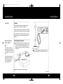
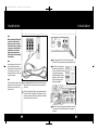
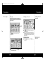
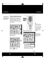
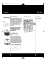
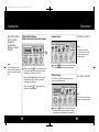
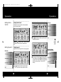
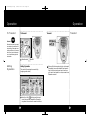
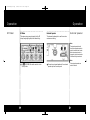
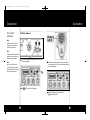
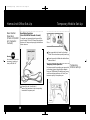
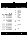
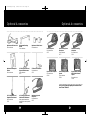
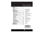
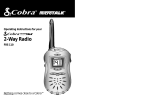
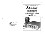
29 UK-English.qx
Contents
6/22/99 12:14 PM
Page 1
How to Use Your
Cobra UK 29 LTD ST
Section A(English)
Features..................................................................................................1
Included Accessories
Controls & Indicators.......................................................................A2
Our Thanks to You .............................................................................A3
SoundTracker™
Installation
Location............................................................................................. 2
Mounting and Connection.........................................................2
Antennas
CB Antenna.......................................................................................6
Marine Installation.........................................................................6
Ignition Noise Interference ..........................................................7
Operating Your UK 29 LTD ST
Turning On Your CB........................................................................8
Setting Channel Selector.............................................................9
Setting Band Selector...................................................................9
Calibrating For SWR (Standing Wave Ratio)..........................10
To Receive..........................................................................................12
Selecting a Channel.......................................................................13
S-Meter...............................................................................................13
SoundTracker™ System................................................................14
Activating SoundTracker ™ ..........................................................15
NB-ANL/ANL/Off (Noise Blanker/Automatic.........................16
Noise Limiter Switch)
Dimmer Switch................................................................................17
RF Gain Control................................................................................17
Setting Delta Control....................................................................18
Setting Squelch...............................................................................18
To Transmit........................................................................................20
Setting Dynamike...........................................................................20
Transmit..............................................................................................21
RF Meter.............................................................................................22
External Speaker.............................................................................23
PA (Public Address)........................................................................24
Home And Office Set-Up .............................................................26
Temporary Mobile Set-Up ...........................................................27
How Your CB Can Serve You..........................................................28
A Few Rules You Should Know ..................................................28
LocalLaws or Regulations...........................................................29
CB 10-Codes.....................................................................................30
Frequency Ranges.............................................................................32
UK 29 LTD ST Specifications.........................................................33
Accessories............................................................................................34
Deutsch ................................................................................Abschnitt B
Español.....................................................................................Sección C
Français ....................................................................................Section D
Italiano .....................................................................................Sezione E
Features of This Product
• Complies With UK MPT 1382
• 2.75 metre microphone cord
• 40 UK CB Radio Channels,
40 CEPT (EU) Channels
• SoundTracker ™ System
• Heavy-Duty Dynamic
Microphone
• Full 4 Watts FM RF Power Output
• SWR Calibration Meter
• Instant Channel 19 and 9
• Front Panel 4-Pin Microphone
Connector
• Delta Control
• Switchable Automatic Noise
Limiter & Noise Blanker
• Tactile Controls
• Illuminated Front Panel
• Dimmer Control
CAUTION
RISK OF ELECTRIC SHOCK
DO NOT OPEN
!
CAUTION: TO REDUCE THE RISK OF ELECTRIC
SHOCK DO NOT REMOVE COVER (OR BACK)
NO USER SERVICEABLE PARTS INSIDE
REFER SERVICING TO QUALIFIED SERVICE
PERSONNEL
1
!
29 UK-English.qx
6/22/99 12:14 PM
Page 2
Installation
Installation
Location
Location
Plan location of transceiver and microphone
bracket before starting the installation.
Select a location that is convenient for operation,
yet does not interfere with the driver or passenger.
The transceiver is usually mounted to the underside of the dash with the microphone bracket
beside it.
Mounting and
Connection
Mounting and Connection
1
Note
The transceiver is held in the
universal mounting bracket by
two thumbscrews which allow
for adjustment at a convenient
angle.
Hold the radio with the mounting bracket in
the exact desired location. If there is no interference, remove the bracket and use it as a
template to mark the location for the mounting screws.
3
The bracket includes two selftapping screws and star washers.The mounting must be
mechanically strong and
conveniently located.
Connect the antenna cable plug to the receptacle marked “ANT” on the back of the unit.
cb transceiver
2
Drill the holes and secure the bracket.
continued
2
3
29 UK-English.qx
6/22/99 12:14 PM
Page 4
Installation
Installation
Note
Before installing the CB radio,
visually check the vehicle’s
battery connection to determine which terminal, positive
or negative, is earthed to the
engine block (or chassis). A
negatively earthed vehicle
has its negative lead earthed
to the chassis.
Note
Connecting to a fuse circuit controlled by the ignition switch
prevents the unit from being left
on accidentally, and also permits operating the unit without
running the engine.
6
Plug power cable into back of unit mar ked
“Power”. Be sure to observe polarity markings.
7
Mount the microphone
bracket on right side of
the unit (nearer the driver)
using two screws supplied. Bracket should be
placed under the dash
so that microphone is
readily accessible.
8
Attach the 4-pin microphone cable to receptacle on front of unit and Install unit in bracket
securely.
Note
In positive earth vehicles the red
wire goes to the chassis and the
black wire is connected to the
ignition switch.
4
4
In a negative earthed vehicle, connect the red
lead of the DC power cord to an accessory 12
volt fuse.
5
Connect the black lead to the negative side of
the vehicle. This is usually the chassis. Any convenient location with a good electrical contact
(remove paint) may be used.
5
29 UK-English.qx
6/22/99 12:14 PM
Page 6
Antennas
Ignition Noise Interference
CB Antenna
CB Antenna
The antenna is critical in affecting transmission
distance. Only a properly matched antenna system will allow maximum power output. Cobra
For optimum performance in
passenger cars the ideal anten- loaded type antenna models are highly recommended for most installations. Consult your
na location is on the centre of
the roof. Second choice is on the Cobra dealer for further details .
Note
centre of the boot.
Note
Antenna must be earthed to the
chassis of the vehicle.
1
A standard antenna connector is provided
on the transceiver for easy connection.
Use of a mobile receiver at low signal levels is
normally limited by the presence of electrical
noise. The primary source of noise in cars is from
the alternator and the ignition system. Typically,
when signal level is adequate, the background
noise does not present a serious problem. Also,
when extremely low-level signals are being
received, the transceiver may be operated with
the vehicle’s engine turned off. The unit requires
very little current and therefore will not significantly discharge the vehicle’s battery.
Even though the Cobra UK 29 LTD ST has an automatic noise limiter, in some installations ignition
interference may be high enough to make good
communications impossible. Many possibilities
exist and variations between vehicles require
different solutions. Consult your COBRA dealer or
a 2-way radio technician for help in locating the
source of a severe noise.
Marine Installation
The transceiver will not operate at maximum efficiency in a boat without an earth plate, (unless it
has a steel hull). Before attempting installation ,
consult your dealer for information regarding an
adequate earthing system and prevention of
electrolysis between fittings in the hull and water.
6
7
29 UK-English.qx
6/22/99 12:14 PM
Page 8
Operation
Operation
Turning On
Setting Channel
Selector
Setting Channel Selector
Turning On
Make sure the power cord, antenna and microphone are connected to their proper connectors
before starting.
1
2
1
The CB/PA button should be in the
CB position.
The CH19/CH9/NOR switch should be in
the NOR position
Select
one of forty channels and adjust
volume.The selected channel is indicated by
the LED readout directly above the channel
selector knob.
Setting Band
Selector
Setting Band Selector
1
2
8
Rotate the On/Off Volume knob
a normal listening level.
Select
band Selector: either UK 40
channels FM or EU European 40 channels
FM,(CEPT).
clockwise to
9
29 UK-English.qx
6/22/99 12:14 PM
Page 10
Operation
Calibrating For
SWR (Standing
Wave Ratio)
Operation
Calibrating for SWR (Standing Wave Ratio)
SWR calibration is done to properly adjust the
length of the antenna and to monitor the quality
of the coaxial cable and all RF connections.
This calibration is critical in order to achieve optimum performance.
Note
3
1
Select
Push and hold microphone button.
Note
The reading will be slightly
higher on Channels 1 and 40
compared to Channel 20.
channel 20.
4
2
Calibration must be made in an
open area (never in a garage).
Vehicle doors must be closed. No
one should be standing near the
antenna.(See your antenna
directions for more complete
information).
Switch to the
CAL position.
While holding microphone button adjust
the SWR CAL knob so
that the meter needle
swings to the CAL ▼
mark on the meter (located on the right).
continued
10
11
29 UK-English.qx
6/22/99 12:14 PM
Page 12
Operation
Operation
Selecting A
Channel
Selecting A Channel
Note
Note
Switch to 9 or 19 for instant
access to these channels.
With the S/RF-SWR-CALswitch
in the SWR position the meter
needle should ideally be as far
to the left as possible.
Anything over 3 is not acceptable. A slight antenna height
adjustment (higher or lower)
may be required. Repeat
relcalibration steps.
To Receive
5
6
While still holding down the microphone
button,set the S/RF-SWR-CAL switch to the
SWR position, to read the SWR reading.
Repeat the same steps 2 to 5 on Channel 1
and 40. This will check SWR for all channels.
1
Switch to
NOR to select desired channel.
S-Meter
S-Meter
Swings proportionately to strength of incoming
signal when receiving.
To Receive
1
1
12
Rotate the
On/Off Volume knob clockwise.
The green RX/TX LED will be illuminated.
The S/RF switch must be in the S/RF position
to read the meter.
13
29 UK-English.qx
6/22/99 12:14 PM
Page 14
Operation
Operation
The SoundTracker TM System
Note
SoundTracker™ gives you
clearer, cleaner reception to
improve CB communications
while on the air.
Activating SoundTracker™
While previous systems only “blanket out” or limit
noise in higher sound frequencies, the revolutionary new SoundTrackerTM System actually reduces
noise while leaving the signal intact in the reception mode. In the transmission mode, it actually
strengthens the signal,providing you with a
significant reduction in noise on reception
and transmission.
Sound clarity is measured by the ratio
of the signal level to the noise level.
The higher the signal-to-noise ratio,
the better the sound.
How SoundTracker TM Works
1
Activating
SoundTracker™
Push and release the
ST button. Red LED
is illuminated when SoundTracker™ is
turned on.
On Reception - “Cuts noise coming in”
With a normal CB, distant signals fall below
the squelch level and are unintelligible. With a
SoundTrackerTM CB, the noise level is cut by up to
90%,which increases the signal-to-noise ratio
and dramatically improves signal clarity.This also
allows you to reduce the squelch level significantly, which greatly expands your listening range.
On Transmission - “Strengthens signals going out”
A SoundTrackerTM CB strengthens the transmit
signal by more effectively using the available RF
power output of the CB. The result is improved
transmission signal clarity and an expanded
transmission range.
14
15
29 UK-English.qx
6/22/99 12:14 PM
Page 16
Operation
NB-ANL/ANL/
OFF (Noise
Blanker /
Automatic
Noise Limiter)
Switch
Operation
NB-ANL/ANL/OFF (Noise
Blanker/Automatic Noise Limiter) Switch
Dimmer Control
Dimmer Control
Note
The Dimmer controls the
brightness of the front panel,
signal strength meter and
channel display.
Note
1
The RF noise blanker is very
effective in reducing repetitive
noises such as ignition interference.
1
When switched to ANL the Automatic Noise
Limiter is activated. This helps reduce noise
created by the vehicle’s electronics.
When switched to NB/ANL position the RF
Noise Blanker is also activated, providing
increased noise filtration.
Rotate the
Dimmer knob clockwise for maximum brightness;anticlockwise for minimum
RF Gain Control
The RF Gain is used to optimize reception in
strong or weak signal areas.
RF Gain Control
When switched to OFF position all noise
filtration will be turned off.
Note
The RF Gain is used to optimiz e
reception in weak signal areas.
1
16
Rotate the
RF Gain knob anticlockwise to
reduce gain in strong signal areas. In weak
signal areas turn clockwise to increase gain.
17
29 UK-English.qx
6/22/99 12:14 PM
Page 18
Operation
Setting Delta
Control
Operation
Setting Delta Control
Gate open
Delta Tone Control is used to set the desirable
level of received audio.
2
1
2
Setting Squelch
Full
anticlockwise rotation opens the “gate”
allowing all signals in.
Switch to Delta+ or Delta - to control tuning.
Rotate the Tone Control to desired level.
Setting Squelch
Squelch is the “control gate” for incoming signals.
Gate set to Desired
Squelch Setting (DSS)
Gate closed
3
1
18
To achieve the Desired Squelch Setting (DSS),
turn the Squelch control
anticlockwise until
you hear noise. Now turn the control clockwise
until the noise just stops. This is the DSS
setting.
Full
clockwise rotation closes the “gate”
allowing only very strong signals to enter.
19
29 UK-English.qx
6/22/99 12:15 PM
Page 20
Operation
To Transmit
Operation
Transmit
Transmit
To Transmit
Caution!
Be sure the antenna is properly
connected to the radio before
transmitting. Prolonged transmitting without an antenna,or
with a poorly-matched antenna, can cause damage to the
transmitter.
1
Setting
Dynamike
Select desired
channel.
Setting Dynamike
This controls the microphone sensitivity
(outgoing audio level).
1
20
1
Push and hold microphone button to transmit.
Transmitter is now activated. When transmitting, hold the microphone two inches from
your mouth and speak in a clear, normal voice.
Release to receive.
Initially, set fully
clockwise so that maximum voice volume is available. Dynamike
may have to be reduced in some conditions.
21
29 UK-English.qx
6/22/99 12:15 PM
Page 22
Operation
RF Meter
Operation
RF Meter
External Speaker
This meter swings proportionately to the RF
output (outgoing signal) while transmitting.
The external speaker jack is used for remote
receiver monitoring.
External Speaker
Note
The external speaker should
have 8-ohm impedance and be
rated to handle at least 4 watts.
When the external speaker is
plugged in,the internal speaker
is automatically disconnected.
Note
1
22
The S/RF-SWR-CAL switch must be in the
S/RF position.
1
Connect an external speaker to the external
speaker jack on the rear panel.
Cobra external speakers are
rated at 10 watts.
23
29 UK-English.qx
6/22/99 12:15 PM
Page 24
Operation
PA (Public
Address)
Operation
PA (Public Address)
Note
Speaker should have 8-ohm
impedance and be rated to
handle at least 4 watts.
Note
The speaker should be directed
away from the microphone to
prevent acoustic feedback.
1
Note
Connect an external PA speaker to the PA jack
on the rear panel.
3
Push and hold microphone button and speak
in a normal voice.Your voice will now transmit
on the PA speaker.
4
Adjust PA speaker volume with the
Dynamike control.
Activity on the CB channel
will be heard through the PA
speaker. Adjust Volume Control
for normal listening level.
2
24
Set
CB/PA switch to PA position.
25
29 UK-English.qx
6/22/99 12:15 PM
Page 26
Home And Office Set-Up
Base Station
Operation
(From 220/240V
AC Domestic
Current)
Temporary Mobile Set-Up
Base Station Operation
(From 220/240V AC Domestic Current)
To operate your transceiver from home or office
you will need a 13.8 volt DC Power Pack rated at a
minimum of 2 amps, and a properly installed base
station antenna.
Warning!
Do not attempt to operate this
transceiver by connecting it
directly to 220/240 V AC.
2
Plug power cable into back of unit mar ked
“Power”. Be sure to observe polarity markings.
3
Connect properly installed and matched base
station antenna.
Temporary Mobile Operation
For temporary mobile operation you may want to
purchase an optional cigarette lighter adapter
from your COBRA dealer. This adapter and a magnetic mount antenna allow you to “install” your
transceiver quickly for temporary use.
1
26
Temporary
Mobile Set-Up
Connect the red (+) and black (-)
leads of the transceiver to the corresponding
terminals of the power pack.
27
29 UK-English.qx
6/22/99 12:15 PM
Page 28
How Your CB Can Serve You
•
•
•
•
•
•
•
•
A Few Rules
You Should
Know
Warn of traffic problems
Provide weather and road data
Provide help in an emergenc y
Provide direct contact with home or office
Get local information to find destination
Communicate with family and friends
Suggest spots to eat and sleep
Keep you alert while travelling
A Few Rules You Should Know
A. Conversations should not last more than 5 minutes with another station. A one-minute break
should be taken to let others use the channel.
B. You should not blast others off the air by use
of illegally amplified transmitters or illegally
high antennas.
C. You should not use CB to promote illegal
activities.
D. Bad language should not be used.
E. You should not transmit music with a CB.
F. You should not use your CB to sell
merchandise and/or professional services.
28
How Your CB Can Serve You
Local Laws or Regulations
Local Laws or
Regulations
THE USE OF THIS CB PRODUCT INVOLVES
THE PUBLIC AIRWAYS AND ITS USE MAY BE
SUBJECT TO LOCAL LAWS OR REGULATIONS. BEFORE USING THE PRODUCT YOU
SHOULD CHECK TO SEE THAT THE CONTEMPLATED USE DOES NOT VIOLATE ANY
APPLICABLE LOCAL LAW OR REGULATION.
29
29 UK-English.qx
6/22/99 12:15 PM
Page 30
How Your CB Can Serve You
CB 10-Codes
CB 10-Codes
Citizen Bands have adopted the “10-CODES” for
standard questions and answers. These codes
provide quick and easy communication,especially
in noisy areas. Following are some of the more
common codes and meanings:
Code
10-1
10-2
10-3
10-4
10-5
10-6
10-7
10-8
10-9
Meaning
Receiving poorly
Receiving well
Stop transmitting
OK,message received
Relay message
Busy, stand by
Out of service, leaving air
In service, subject to call
Repeat message
10-10
10-11
10-12
10-13
10-16
10-17
10-18
10-19
10-20
10-21
10-22
10-23
10-24
10-25
10-26
10-27
10-28
Transmission completed, standing by
Talking too rapidly
Visitors present
Advise weather/road conditions
Make pick up at
Urgent business
Anything for us?
Return to base
My location is
Call by phone
Report in person to
Stand by
Completed last assignment
Can you contact
Disregard last info
Moving to channel
Identify your station
30
How Your CB Can Serve You
Code
10-29
10-30
10-33
10-34
10-35
10-36
10-37
10-38
10-39
10-41
10-42
10-43
10-44
10-45
10-50
10-60
Meaning
Time is up for contact
Does not conform to FCC rules
Emergency traffic
Trouble at this station
Confidential information
Correct time is
Breakdown truck needed at
Ambulance needed
Message delivered
Turn to channel
Traffic accident at
Traffic delay at
Have a message for
All units within range please repor t
Break channel
What is next message number?
10-62
10-63
10-64
Unable to copy. Use phone
Net directed to
Net clear
10-65
Awaiting your next message/assignment
10-67
10-70
10-71
All units comply
Fire at
Proceed, transmission in sequence
10-77
Negative contact
10-81
10-82
10-85
Reserve hotel room for
Reserve room for
My address is
10-91
Talk closer to microphone
10-93
10-94
10-99
Check my frequency on this channel
Give me a long count
Mission completed, all units secure
10-200 Police needed at
31
29 UK-English.qx
6/22/99 12:15 PM
Page 32
Frequency Ranges
29 UK LTD ST Specifications
The COBRA UK 29 LTD ST transceiver represents one of the most advanced FM twoway radios used.This unit features advanced Phase Lock Loop (PLL) circuitry providing complete coverage of all 40 CEPT and 40 UK FM CB channels.
CEPT Frequencies
UK Frequencies
Channel
Channel
CB
Freq.
CB
Freq.
Channel In MHz Channel In MHz
Channel
Channel
CB
Freq.
CB
Freq.
Channel In MHz Channel In MHz
1
2
3
4
5
26.965
26.975
26.985
27.005
27.015
21
22
23
24
25
27.215
27.225
27.255
27.235
27.245
1
2
3
4
5
27.60125
27.61125
27.62125
27.63125
27.64125
21
22
23
24
25
27.80125
27.81125
27.82125
27.83125
27.84125
6
7
8
9
10
27.025
27.035
27.055
27.065
27.075
26
27
28
29
30
27.265
27.275
27.285
27.295
27.305
6
7
8
9
10
27.65125
27.66125
27.67125
27.68125
27.69125
26
27
28
29
30
27.85125
27.86125
27.87125
27.88125
27.89125
11
12
13
14
15
27.085
27.105
27.115
27.125
27.135
31
32
33
34
35
27.315
27.325
27.335
27.345
27.355
11
12
13
14
15
27.70125
27.71125
27.72125
27.73125
27.74125
31
32
33
34
35
27.90125
27.91125
27.92125
27.93125
27.94125
16
17
18
19
20
27.155
27.165
27.175
27.185
27.205
36
37
38
39
40
27.365
27.375
27.385
27.395
27.405
16
17
18
19
20
27.75125
27.76125
27.77125
27.78125
27.79125
36
37
38
39
40
27.95125
27.96125
27.97125
27.98125
27.99125
GENERAL
CHANNELS. . . . . . . . . . . . . . . . . . . . . . . 40 CH FM British,40 Channel FM CEPT (EU)
FREQUENCY RANGE. . . . . . . . . . . . . . . 26.965 TO 27.405 MHz FM CEPT
BRITISH FM 40 CH
FREQ. RANGE 27.60125 TO 27.99125
FREQUENCY TOLERANCE . . . . . . . . . . 0.005 %
FREQUENCY CONTROL . . . . . . . . . . . . PLL (PHASE LOCK LOOP) SYNTHESIZER
OPERATING TEMPERATURE
RANGE. . . . . . . . . . . . . . . . . . . . . . . . . . . -20° C TO + 55° C
MICROPHONE . . . . . . . . . . . . . . . . . . . . PLUG-IN DYNAMIC
INPUT VOLTAGE . . . . . . . . . . . . . . . . . . 13.2 V DC nom.(positive or negative earth)
CURRENT DRAIN
TRANSMIT: AM FULL MOD.,1.5A (MAXIMUM)
RECEIVE:SQUELCHED, 0.3A;
FULL AUDIO OUTPUT, 1.2A (NOMINAL)
SIZE
219 mm x 185 mm x 56 mm
(8-5/8” D x 7-9/32”W x 2-13/64”H)
WEIGHT . . . . . . . . . . . . . . . . . . . . . . . . . .1.8 kg (4 LBS.)
ANTENNA CONNECTOR . . . . . . . . . . . .UHF; SO-239
METER . . . . . . . . . . . . . . . . . . . . . . . . . . .ILLUMINATED;INDICATES RELATIVE
POWER OUTPUT, RECEIVED
SIGNAL STRENGTH AND VSWR
TRANSMITTER
POWER OUTPUT . . . . . . . . . . . . . . . . . .4 WATTS FM
MODULATION . . . . . . . . . . . . . . . . . . . .FM (FREQUENCY MODULATION)
FREQUENCY RESPONSE . . . . . . . . . . . .300 TO 3000 Hz
OUTPUT IMPEDANCE . . . . . . . . . . . . . .50 OHMS,UNBALANCED
RECEIVER
SENSITIVITY . . . . . . . . . . . . . . . . . . . . . . .LESS THAN 6 dB µV FOR 20 dB SINAD
SELECTIVITY . . . . . . . . . . . . . . . . . . . . . .6 dB@ 7 kHz, 60 dB@ 10 kHz
IMAGE REJECTION . . . . . . . . . . . . . . . . .80 dB, TYPICAL
ADJACENT-CHANNEL REJECTION . . .60 dB , TYPICAL
IF FREQUENCIES . . . . . . . . . . . . . . . . . .DOUBLE CONVERSION:1ST: 10.695 MHz
2ND:455 kHz
AUTOMATIC GAIN CONTROL (AGC) .LESS THAN 10 dBCHANGE IN AUDIO
OUTPUT FOR INPUTS FROM 10 TO 50,000
MICROVOLTS
RF GAIN RANGE . . . . . . . . . . . . . . . . . . .40 dB
NOISE BLANKER . . . . . . . . . . . . . . . . . . .RF TYPE
SQUELCH . . . . . . . . . . . . . . . . . . . . . . . . .ADJUSTABLE;THRESHOLD LESS THAN 1µV
AUDIO OUTPUT POWER . . . . . . . . . . .4 WATTS
FREQUENCY RESPONSE . . . . . . . . . . . .300 TO 3000 HZ
DISTORTION . . . . . . . . . . . . . . . . . . . . . .LESS THAN 7% @3 WATTS @ 1000 HZ
BUILT-IN SPEAKER . . . . . . . . . . . . . . . . .8 OHMS,5W
EXTERNAL SPEAKER (NOT SUPPLIED) 8 OHMS; DISABLES INTERNAL SPEAKER
WHEN CONNECTED
PA SYSTEM
POWER OUTPUT . . . . . . . . . . . . . . . . . .4 WATTS INTO EXTERNAL SPEAKER
EXTERNAL SPEAKER FOR PA . . . . . . . .8 OHMS,4W MIN.
(NOT SUPPLIED)
(SPECIFICATIONS SUBJECT TO CHANGE WITHOUT NOTICE)
32
33
29 UK-English.qx
6/22/99 12:15 PM
Page 34
Optional Accessories
Optional Accessories
Replacement DC Power Cord
For in-vehicle use
Replacement Mounting
Bracket
For in-vehicle use
Replacement Thumb Screws
For in-vehicle use
Replacement Microphone
Bracket
28” Full Range Centre Load,
Magnetic Mount Antenna
For in-vehicle use
For in-vehicle use
AT 35
25”Glass Mount Antenna
For in-vehicle use
AT 55
Power Microphone
For in-vehicle use
CA 75
Noise Cancelling/Power
Microphone
For in-vehicle use
CA 77
Echo/Noise Cancelling
Microphone
For in-vehicle use
CA 79
Dynamic External Speaker
Noise Cancelling External
Speaker
Dynamic Noise Cancelling
With Talk Back External
Speaker
For in-vehicle use
CS 500
For in-vehicle use
CS 100
For in-vehicle use
CS 300
You Can Find These High-quality Accessories At Your
Local Cobra CB Dealer
39” Full Range Base Load,
Magnetic Mount Antenna
For in-vehicle use
AT 70
44” Full Range, Centre Load,
Dual Band CB/WX Antenna
Allows greater transmission
range while in a moving vehicle.
ATW 400
34
Replacement Dynamic
Microphone
For in-vehicle use
CA 73
35
29 UK-English.qx
6/22/99 12:15 PM
Page 36
UK 29 LTD ST
Cobra Electronics Corporation
6500 West Cortland Street
Chicago, IL60707 USA
www.cobraelec.com
Operating Instructions for your Cobra UK 29 LTD ST CB Radio
Bedienungsanleitung für lhr Modell Cobra UK 29 LTD ST CBFunkgerät
Instructivo de uso de la radio de banda ciudadana (CB) Cobra
UK 29 LTD ST
Instructions d’utilisation du poste de radio CB UK 29 LTD ST
de Cobra
Istruzioni per l’uso del modello Cobra UK 29 LTD ST Radio CB
“Ingenious Products for Easier Communication.”
29 UK-English.qx
6/22/99 12:15 PM
Page 38
The CB Story
What’s Included with Your UK 29 LTD ST
1.
2.
3.
4.
5.
6.
2
CB transceiver
Microphone
Transceiver bracket
Microphone bracket
Operating Manual
DC power cord (not shown)
1
3
4
NOTICE
A licence is required for
use in the UK.CB licensing applications can be
obtained from The Radio
Licensing Centre, P.O.
Box 885, Bristol,BS99
5LG,UK or contact your
local CB dealer for
additional information.
5
A1
29 UK-English.qx
6/22/99 12:15 PM
Page 39
Controls and Indicators
Our Thanks to You
Thank you for purchasing the Cobra UK 29 LTD ST
CB Radio. Properly used, this Cobra product will
give you many years of reliable service.
1. 4-Pin Microphone
Connector
19
2. Power On/Off, Volume
3. Squelch
SoundTracker TM
4. RF Gain/ Dynamike
“Cuts noise coming in...strengthens signals
going out.”
5. Tone
This Patent-pending technology dramatically
improves transmission and reception of CB
signals.
6. Dimmer/SWR CAL
7. Band Selector
8. Channel Selector
The revolutionary SoundTrackerTM System reconfigures the transmission signal,allowing it to be
transferred more efficiently through cluttered
airwaves.
9. LED Channel Display
10. Sound Tracker™ LED
11. RX (Receive)/ TX (Transmit)
LED Indicator
12. Sound Tracker™ On/Off
13. S/RF SWR CAL Switch
Cobra on the World Wide Web:
Frequently Asked Questions
(FAQ) can be found on-line at:
www.cobraelec.com
17 16 15 14 13 11
10
9
18
12
14. Channel 19/Channel 9/
Normal Switch
15. Delta-Tune
1
16. CB/PA Switch
17. NB/ANL ANL Off Switch
2
4
5
6
7
8
At the same time, it significantly reduces the
amount of static on all incoming CB signals.
The end result is cleaner, clearer sounding
reception of signals and a more powerful
transmission which dramatically improves CB
communications.
3
18. Signal Strength Meter
20
19. Microphone
21
Rear Panel
20. Public Address Speaker
Jack
21. External Speaker Jack
22
22. Antenna Connector
23
23. Power Jack
A2
A3