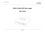
1
VB2SX User Guide VB2SX 20Hz GPS Data Logger User Guide Page 1 of 28 VB2SX User Guide Contents CONTENTS ................................................................................................................................................................................................................................................................ 2 INTRODUCTION ...................................................................................................................................................................................................................................................... 4 FEATURES ................................................................................................................................................................................................................................................................. 4 STANDARD INVENTORY ....................................................................................................................................................................................................................................... 5 OPERATION .............................................................................................................................................................................................................................................................. 6 DISPLAY SCREEN ................................................................................................................................................................................................................................................... 6 FRONT PANEL CONTROLS .................................................................................................................................................................................................................................. 7 MEMORY CARDS .................................................................................................................................................................................................................................................. 11 GETTING STARTED .............................................................................................................................................................................................................................................. 17 VB2SX ‘.VBO’ FILE FORMAT ............................................................................................................................................................................................................................. 19 VBOXTOOLS SOFTWARE ................................................................................................................................................................................................................................... 20 UPGRADING THE FIRMWARE .......................................................................................................................................................................................................................... 21 SPECIFICATION .................................................................................................................................................................................................................................................... 22 CONNECTOR ASSIGNMENTS ............................................................................................................................................................................................................................ 24 CAN BUS DATA FORMAT .................................................................................................................................................................................................................................... 26 MODULE DIMENSIONS........................................................................................................................................................................................................................................ 27 FUSE RESET BUTTON .......................................................................................................................................................................................................................................... 27 CONTACT INFORMATION.................................................................................................................................................................................................................................. 28 Page 2 of 28 VB2SX User Guide EC Declaration of Conformity We declare that this product has been tested to and meet the requirements of: EC Directive 2004/104/EC “Adapting to Technical Progress Council directive 72/245/EEC relating to the radio interference (Electromagnetic Compatibility) of vehicles and amending directive 70/156/EEC on the approximation of the laws of the member states relating to the type-approval of motor vehicles and their trailers.” And has also been assessed, via Technical Construction File, by an independent DTI Competent Body and found to be in conformance with the essential requirements of: EC Directive 89/336/EEC (and amending directives) “Council Directive of 03 May 1989 on the approximation of the laws of the member states relating to electromagnetic compatibility.” DTI Competent Body responsible for issuing certificate of compliance: 3C Test Ltd, Silverstone Technology Park, Silverstone, Northants NN12 8GX Page 3 of 28 VB2SX User Guide Introduction nd The VB2SX represents the 2 generation of GPS data logging system from Racelogic, updating the popular VBOXII and VB2S products with SD card logging and USB communications. Using a powerful GPS engine, the VB2SX can log GPS and other data at 20Hz. The logged data is stored directly onto a SD card for easy transfer to a PC. The VB2SX is compatible with all of the existing peripherals including the Multifunction display, ADC03, TC8, FIM02, Yaw Rate Sensor and Speed Sensor with Slip Angle. Features Non-contact 20Hz speed and distance measurement using GPS VCI CAN input for connection to external CAN systems 1 x CAN Bus interface (on two sockets to allow daisy-chaining) USB interface for live data, upgrading and SD data transferral RS-232 serial interface backup for live data and upgrading SD Card logging 2 x 16bit user configurable analogue outputs (velocity) 2 x Digital outputs (velocity) Brake/event trigger input with 210KHz scan rate OLED screen display with front panel configuration Input voltage 6V to 30V operating range Logging of up to 24 data channels, un addition to up to 13 standard GPS channels Logging rate selectable from 20Hz, 10Hz, 5Hz, 2Hz, 1Hz Page 4 of 28 VB2SX User Guide Standard Inventory Description Qty Racelogic Part # VB2SX 1 VB2SX Mains Charger 1 RLVBACS020 Cigar Lighter adaptor 1 RLCAB010L USB Lead 1 RLCAB042 Serial PC cable 1 RLCAB001 2GB SD Card 1 RLACS083 GPS Magnetic Aerial 1 RLVBACS018 CD ROM containing VBOX software 1 RLVBACS030 VBOX User Manual 1 VB2SXMAN Padded Carrying Case 1 RLVBACS013V4 Page 5 of 28 VB2SX User Guide Operation Display Screen The Display screen will display data when operating it also displays all the menus required to configure the VB2SX via the front panel controls. On start-up, the display screen shows the unit’s firmware version. During normal operation, the display screen displays Speed (mph or km/h) and the logged file name, as well as the number of satellites that the VB2SX has locked on to. There are also two satellite status displays. OK (Green): Indicates that the VB2SX has sufficient satellites locked to allow normal operation. SATS (Yellow): This flashes to indicate that the VB2SX has insufficient satellites and will not be able to operate at all. WAAS/20cm/40cm (Orange): This indicates that the corresponding DGPS corrections are available and being used by the unit. Logged File name: When an SD card is inserted the file name of the logged file appears on the screen whilst the file is open. A small disk icon to the left of the file name indicates that data is being logged. Page 6 of 28 VB2SX User Guide Front Panel Controls The VB2SX can be configured using the front panel buttons, which enables configuration without the need for a computer. From the main screen, press the’■’ button to enter the configuration screen. Once in the configuration screen, press the ‘◄’and ‘►’ buttons to highlight the next or previous choice in any menu, and press ’■’ to select the highlighted option. Some menus contain sub-menus, for example the Analogue and Digital Output menus contain separate menus for each parameter. Main Menu SETTINGS Press’■’ and then the ‘◄’ and ‘►’ buttons to enter settings options sub-menus. UNITS USB MODE CAN MODE LOG OPTIONS SERIAL RATE GPS TIME OFFSET BACK COLD START Press’■’ to perform a GPS cold start SMOOTHING OUTPUTS Press’■’ to enter the Smoothing options sub-menus Press’■’ to enter the outputs options sub-menus. LAT ACC LONG ACC DIGITAL 1 DIGITAL 2 ANALOGUE 1 ANALOGUE 2 Press’■’ to enter sub menu and ‘◄’ and ‘►’ buttons to amend smoothing levels in 0.1 increments. Page 7 of 28 EXIT Press’■’ to exit the setup menu and cause the settings to be saved in EEPROM VB2SX User Guide Settings Menu UNITS USB MODE CAN MODE LOG OPTIONS Press the ‘◄’ and ‘►’ buttons to choose between the following units: Press the ‘◄’ and ‘►’ buttons to choose between the following USB options: Press’■’ and then the ‘◄’ and ‘►’ buttons to choose between the following modes: Press’ the ‘◄’ and ‘►’ buttons to choose between the logging options: Press’■’ and then the ‘◄’ and ‘►’ buttons to choose between the serial data rates: Km/h SERIAL PORT CARD READER LOG CONDITIONS: To select either Log Continuously or log When Moving Choose from either 20,10, 5, 2 or 1Hz MPH VCI MODE* To connect any external CAN modules to the input of the VB2SX RACELOGIC MODULES MODE To connect Racelogic CAN modules to the RLVB2SX5 (input or output) LOG RATE: Select log rate – either 20,10, 5, 2 or 1Hz KNOTS BACK Return to Settings menu GPS TIME OFFSET BACK Press’ the ‘◄’ and ‘►’ buttons to choose between the GPS options: Press’ the ‘◄’ and ‘►’ buttons to offset the UTC time in 30 minute intervals to allow the VBOX to represent local time. Shown in the header of the logged file. Press’■’ to return to the settings menu DYNAMIC MODE DGPS MODE KALMAN FILTER BACK *Note: In VCI Mode, the VB2SX cannot output CAN data or input data from Racelogic modules. Page 8 of 28 SERIAL RATE VB2SX User Guide SETTINGS - GPS MENU DYNAMIC MODE DGPS MODE KALMAN FILTER Press’■’ and then the ‘◄’ and ‘►’ buttons to select the required dynamics. Press’■’ and then the ‘◄’ and ‘►’ buttons to select the DGPS settings. Press’■’ and then the ‘◄’ and ‘►’ buttons to set Kalmann filter options. HIGH DYNAMICS Essential for brake testing and lane changing manoeuvres. OFF No DGPS applied – standard position accuracy 3m CEP POSITION LEVEL Smoothes the positional data NORMAL Select this for standard testing – speed, distance, etc. WAAS – position accuracy 1.8m CEP LOW DYNAMICS Select this for route mapping and similar tests where the level of dynamic response is not important. BACK Press’■’ to return to the GPS menu VELOCITY LEVEL Smoothes the velocity data 40CM – position accuracy 40CM* 20CM – position accuracy 20CM* *Note: These accuracies are only achievable in conjunction with a DGPS base station OUTPUTS MENU (Channel 1 and 2) DIGITAL 1 DIGITAL 2 ANALOGUE 1 ANALOGUE 2 Press’■’ and then the ‘◄’ and ‘►’ buttons to select output conditions for digital output 1 Press’■’ and then the ‘◄’ and ‘►’ buttons to select output conditions for digital output 2 Press’■’ and then the ‘◄’ and ‘►’ buttons to select output conditions for analogue output 1 Press’■’ and then the ‘◄’ and ‘►’ buttons to select output conditions for analogue output 2 OUTPUT: PULSES PER METRE (velocity) MAX VELOCITY (velocity) MAX VALUE (Lat ACC & Long ACC) MAX FREQUENCY (Lat ACC & Long ACC) TEST BACK OUTPUT: PULSES PER METRE (velocity) MAX VELOCITY (velocity) MAX VALUE (Lat ACC & Long ACC) MAX FREQUENCY (Lat ACC & Long ACC) TEST BACK OUTPUT: VALUE @ +5V VALUE @0V (Velocity) VALUE @ -5V (Lat ACC & Long ACC) TEST BACK OUTPUT: VALUE @ +5V VALUE @0V (Velocity) VALUE @ -5V (Lat ACC & Long ACC) TEST BACK Page 9 of 28 BACK Press’■’ to return to the main menu VB2SX User Guide DIGITAL SETUP MENU (Digital 1 and Digital 2) OUTPUT Press’■’ and then use the ‘◄’ and ‘►’ buttons to select from: Velocity Long ACC Lat ACC VELOCITY PULSES PER METRE VELOCITY MAX VELOCITY LONG ACC / LAT ACC MAX VALUE LONG ACC / LAT ACC MAX FREQUENCY Press’■’ and then use the ‘◄’ and ‘►’ buttons to set the number of pulses per metre. Then press ’■’ to confirm. Press’■’ and then use the ‘◄’ and ‘►’ buttons to set the level of the maximum Velocity. Then press ’■’ to confirm. Press’■’ and then use the ‘◄’ and ‘►’ buttons to set the level of the maximum Long ACC or Lat ACC level. Then press ’■’ to confirm. Press’■’ and then use the ‘◄’ and ‘►’ buttons to set the frequency of the maximum Long ACC or Lat ACC level. Then press ’■’ to confirm. 0.1-120 pulses per metre in 0.1 steps 0-400km/h in 0.1km/h steps 0.5g to 2g in 0.1 g steps 1-50kHz in 0.1kHz steps TEST BACK Press’■’ and then use the ‘◄’ and ‘►’ buttons to set a test value that the Digital output will simulate. Then press ’■’ to quit. Press’■’ to exit the digital setup menu and cause the settings to be saved in EEPROM ANALOGUE SETUP MENU (Analogue 1 and Analogue 2) OUTPUT Press’■’ and then use the ‘◄’ and ‘►’ buttons to select from: Velocity Long ACC Lat AC VALUE @ +5V Press’■’ and then use the ‘◄’ and ‘►’ buttons to set the Velocity, Long ACC or Lat ACC level to represent +5V. Then press ’■’ to confirm. 1-400km/h in 1km/h steps, or -1g to 2g in 0.1 g steps VALUE @ -5V (0V for Velocity) Press’■’ and then use the ‘◄’ and ‘►’ buttons to set the Velocity, Long ACC or Lat ACC to represent 0V (velocity) or -5V (Lat ACC & Long ACC). Then press ’■’ to confirm. 0-399km/h in 1km/h steps, or -2g to 1g in 0.1g steps Page 10 of 28 TEST Press’■’ and then use the ‘◄’ and ‘►’ buttons to set a test value that the analogue output will simulate. Then press ’■’ to quit. BACK Press’■’ to exit the analogue setup menu and cause the settings to be saved in EEPROM VB2SX User Guide Memory Cards The VB2SX stores logged data onto SD Cards. The supplied SD cards are already optimised for use on the VB2SX and as such do not need formatting before use. Should the SD Card need formatting due to card errors it should only be formatted using the ‘Format Compact Flash’ option in the VBOXTools software. The SD Card will need to be inserted into an SD Card reader (or a VB2SX set to ‘Card Reader’ USB Mode) for this to work. When logging data to an SD Card the OLED display will show the name of the current file at the bottom of the display. It is important not to remove the SD Card while the VB2SX is logging. If the card is removed while the VBOX is writing data to it, there is a risk that the data file may be corrupted resulting in loss of data. If ‘Log only when moving’ is the logging mode selected then wait a short time after the vehicle has stopped for logging to finish and the filename to disappear from the screen. If ‘Log continuously’ is selected, press the Start/stop logging switch if connected or enter then exit the on-board configuration screen. It is recommended that files are removed from the disk regularly as writing continuously with out fragments is easy. The more file fragments the harder it is to stream data to the card. Page 11 of 28 VB2SX User Guide GPS Antenna The GPS Antenna supplied with the VB2SX is a 3.5v active antenna. For the best possible signal quality, it is important to maintain a clean connection between the antenna and the VBOX. Before fixing the antenna to the VBOX, ensure that there are no dust particles in either connector. Replacement antennas are available by contacting your VBOX distributor. The antenna is a magnetic mounting type for quick and simple mounting to the vehicle roof. For optimum GPS signal reception, make sure that the antenna is fitted to the highest point of the vehicle away from any obstructions that may block satellite reception. The GPS antenna works best with a metal ground plane underneath (eg. Vehicle roof). Please also note that when using any GPS equipment, a clear sky view is important. Objects in the surrounding area such as tall buildings or trees can block the GPS signal causing a reduction in the number of satellites being tracked, or introducing reflected signals that can decrease the accuracy of the system. GPS antennas require a ground plane to operate correctly. Usually, the metal roof of a vehicle performs this function. However, if a test requires an antenna to be placed off of the vehicle, then a special Ground Plane ‘mushroom-style’ antenna must replace the off-vehicle antenna, as these antennas are capable of operating without a ground plane. The Ground Plane ‘mushroom’ style antennas RLVBACS065 are available from your VBOX distributor. RLVBACS065 “mushroom” type Ground Plane Antenna Page 12 of 28 VB2SX User Guide DIGITAL and ANALOGUE OUTPUTS The digital outputs on connectors OUT1 and OUT2 are a frequency/pulse output corresponding to velocity, long ACC and Lat ACC. The frequency range is adjustable in software or via the front panel controls. The analogue outputs on connectors OUT1 and OUT2 output a 0V to +5V DC signal corresponding to velocity and a -5V to +5V signal corresponding to Long ACC and Lat ACC. The volts range is adjustable in software or via the front panel controls. Page 13 of 28 VB2SX User Guide Digital Inputs The DIGITAL I/O socket contains the two digital inputs for the VB2SX. Digital input 1 is also referred to as the Brake trigger input. This input is connected to an internal timer capture module that is able to record precisely an event time for use in brake distance calculation. This period of time is called the trigger event time, and is logged as the value in milliseconds between the trigger event and the last GPS sample. A hand-held brake trigger is also available to allow the user to record marker events in the VB2SX data file. A remote logging on/off switch is also available for ease of use and when the front panel switch is not accessible. Page 14 of 28 VB2SX User Guide CAN / RS232 Ports / USB The VB2SX is equipped with a CAN Bus interface, a RS232 serial port and an USB port. The RS232 port or USB is used for all communication between the VBOX and laptop PC. The USB or RS232 ports are able to transmit live data from the VBOX to the PC for viewing and performing real-time tests. Note only the USB port is used for firmware upgrading The CAN Bus port is available in either the socket labelled CAN or the socket labelled Serial. This CAN port has three functions, CAN Input in VCI mode, CAN Input in Racelogic Modules Mode (Internal Mode) and CAN output in Racelogic Modules Mode (External Mode). VCI Mode: This mode should be selected if you wish to log incoming CAN data from external modules from other manufacturers. Note in VCI mode no CAN output or connection to Racelogic modules is possible. Racelogic Modules mode This mode should be selected when Racelogic modules are connected to the VBOX or VBOX CAN output is required. Depending upon configuration, VBOX Tools software should be set as follows: Internal Mode: This mode should be selected when Racelogic input modules are connected to the VBOX. In this mode the CAN id’s and Baud rate are non configurable. External Mode: This CAN mode should be used when a VBOX CAN data output is to be used by an external CAN device such as a Data acquisition system. In this mode the attributes of the CAN output stream are configurable by the user in VBOXTools See the section ‘Setup’ in the VBOX software manual. Note that Internal Mode and External mode are not configurable from the front panel of the VB2SX The Socket labelled CAN also contains a secondary RS232 port for direct connections to the GPS engine for Local DGPS correction connection. Page 15 of 28 VB2SX User Guide Using the USB cable The first time you use the USB cable, you will need to follow the instructions below. Connect the USB cable between the VB2SX and your computer. Your computer will now recognise the presence of a new device, after a period of time a ‘Found New Hardware Wizard’ window will appear. See below. Click the option ‘No, not this time’ and click ‘Next’ (see image, right) A new window will appear at this window click ‘Next’ (see image, below) A new ‘Hardware Installation’ window will appear. Click the button labelled ‘Continue Anyway’. At the last window click ‘Finish’ to complete the installation. After a short period of time a window will ask you if you wish to reboot your computer, select ‘NO’ Now disconnect the power from the VB2SX and then reconnect the power, your computer will now recognise the Slip angle sensor. When you run the VBOXTools software it will recognise the USB connections Page 16 of 28 VB2SX User Guide Getting Started Required equipment (All supplied as standard unless specified) VB2SX Fully charged battery pack or Cigar lighter 12v adapter lead GPS Antenna Blank SD card USB/RS232 Cable VBOX Software CD Laptop PC(not supplied) 1.Install Software 2.Place VBOX in vehicle 3.Fit antenna connector to VBOX 4. Mount GPS antenna on vehicle roof 5.Connect USB or serial cable (CAB01) to laptop 6. Connect other end of USB or serial cable to VBOX Page 17 of 28 VB2SX User Guide 7. Connect the power cable/ battery pack to the VBOX 8. If using 12v power cable, connect to vehicle 9. See below 9. With the power applied, the Display screen will illuminate. The VB2SX will start searching for satellites. The ST led will indicate the number of satellites currently in lock. For best results ensure the VBOX has acquired a lock on 5 or more satellites, essential for quality signal reception. When using the VBOX for the first time or when using the VBOX after a long period of time, allow the VBOX to sit for between 5 and 10 minutes to re-collect data needed to track satellites. As the vehicle begins moving, the display will show a file-writing screen then show the normal display screen with the file name of the current file, with a small disc icon whenever the VBOX is logging. Page 18 of 28 VB2SX User Guide VB2SX ‘.VBO’ file format The VB2SX data files are saved in standard space de-limited text format. This allows the data to easily be imported into third party applications such as word processors or spreadsheets. The files each contain a header section before the main data that describes the channel content and information about the VB2SX such as serial number and firmware version. The [Column names] parameter specifies the data in each column of the data section. An example of a VBOX VBO file is shown on the right. File created on 16/11/2006 @ 15:42 [header] satellites time latitude longitude velocity kmh heading height Event 1 time [channel units] Note that the File created time and date is derived from UTC time and date, so will not reflect your local time unless you logged data on the Greenwich Meridian. [comments] (c)2001 - 2005 Racelogic VBII SX V01.01 Bld. 0131 GPS Firmware : SX2g Serial Number : 00007194 Log Rate (Hz) : 20.00 Kalman Filter - Pos : 0 Vel : 0 GPS Time [module Information] [column names] sats time lat long velocity heading height event-1 [data] 006 154215.35 +3119.240616 +00058.826374 000.000 000.00 +0158.13 0.00000 006 154215.40 +3119.240620 +00058.826371 000.820 326.60 +0158.12 0.00000 006 154215.45 +3119.240624 +00058.826378 000.000 000.00 +0158.13 0.00000 006 154215.50 +3119.240626 +00058.826378 000.000 000.00 +0158.12 0.00000 006 154215.55 +3119.240625 +00058.826380 000.000 000.00 +0158.13 0.00000 006 154215.60 +3119.240621 +00058.826378 000.000 000.00 +0158.12 0.00000 006 154215.65 +3119.240619 +00058.826379 000.000 000.00 +0158.12 0.00000 006 154215.70 +3119.240620 +00058.826381 000.000 000.00 +0158.13 0.00000 006 154215.75 +3119.240622 +00058.826380 000.000 000.00 +0158.12 0.00000 006 154215.80 +3119.240624 +00058.826382 000.000 000.00 +0158.12 0.00000 006 154215.85 +3119.240627 +00058.826378 000.000 000.00 +0158.12 0.00000 006 154215.90 +3119.240627 +00058.826375 000.000 000.00 +0158.12 0.00000 Page 19 of 28 VB2SX User Guide VBOXTools Software The VBOXTools software is used for configuration of the VB2SX and also for analysis of the VBO data files. For further information on the VBOXTools software refer to the VBOXTools Software manual supplied with VB2SX. Page 20 of 28 VB2SX User Guide Upgrading the Firmware Occasionally Racelogic releases new versions of firmware code for VBOX products, this maybe to fix bugs or to add new features. New firmware for the VB2SX is loaded into the unit using a computer and the supplied USB cable. The latest firmware upgrade (.ruf) file for the Speed Sensor is available from the Racelogic website in the VBOX downloads section. http://www.racelogic.co.uk/2003/vbox/downloads.htm If you need the latest file, download it from the website and copy it to your computer. If you are connecting your slip angle sensor to your computer with the USB cable for the first time then follow the instructions in the Section ‘Using the USB cable‘ earlier in this manual before following the instructions below. How to upgrade the firmware Press and hold the ‘◄’ button whilst the power is connected to the VB2SX. The screen will now display the UPGRADER screen, showing that it is ready for upgrading Connect the USB cable to your computer. Double click on the .ruf firmware upgrade file that you have downloaded from the website This will automatically run the upgrade program where you will see the progress of the upgrade. At the end of the process disconnect the USB and then disconnect and reconnect the power. If you have any questions regarding upgrade of VBOX, please do not hesitate to contact [email protected] Page 21 of 28 VB2SX User Guide Specification GPS Velocity Accuracy Units Update rate Maximum velocity Minimum velocity Resolution 0.1 Km/h (averaged over 4 samples) Km/h or Mph 20 Hz 1000 Mph 0.1 Km/h 0.01 Km/h Absolute Positioning Accuracy Accuracy with DGPS Update rate Resolution 3m 95% CEP** 1.8m 95% CEP** 20 Hz 1 cm Heading Resolution Accuracy Acceleration Accuracy Maximum Resolution Update rate Memory SD/MMC Card Recording time Distance Accuracy Units Update rate Resolution Height accuracy Height accuracy with DGPS 0.05% (<50cm per Km) Metres / Feet 20Hz 1cm 6 Metres 95% CEP** 2 Metres 95% CEP** Brake Stop Accuracy Accuracy +/-10cm Time Resolution Accuracy 0.01 s 0.01 s 0.01° 0.1° Power Input Voltage range Current 6v-30v DC Typically 560mA 0.5% 20 G 0.01 G 20Hz Environmental and physical Weight Size Operating temperature Storage temperature Approx500 grammes 119mm x 128mm x 30mm -30C to +60C -40C to +80C Definitions ** CEP = Circle of Error Probable 95% CEP (Circle Error Probable) means 95% of the time the position readings will fall within a circle of the stated diameter Dependent on flash card capacity* * Approximately 4.3Mb per hour used when logging GPS data at 20Hz Page 22 of 28 VB2SX User Guide Outputs CAN Bus Bit rate Identifier type Data available Analogue Voltage range Default setting * Accuracy Update rate 125Kbits, 250Kbits ,500Kbits & 1Mbit selectable baud rate Standard 11bit or extended 2.0A Satellites in View, Latitude, Longitude, Velocity, Heading, Altitude, Vertical velocity, Distance, Longitudinal acceleration & lateral acceleration, Distance from trigger, Trigger time, trigger Velocity 0 to 5Volts DC Velocity 0.0125Volts per Km/h (0 to 400Km/h) 0.1 Km/h 20Hz Digital Frequency range Default setting * DC to 44.4Khz 25Hz per Km/h (0 to 400Km/h) Accuracy Update rate 90 pulses per metre 0.1Km/h 20Hz * The range settings can be adjusted by the user in software or via the front panel buttons Inputs CAN Bus VCI CAN mode Racelogic modules mode Digital Brake/Event Trigger On/Off Logging control Up to 16 channels from any external CAN module Up to 24 channels from any combination of ADC02, ADC03, FIM02, TC8, Yaw sensor or CAN02 Selectable signal polarity. 16bit timer capture with 5μs resolution Remote log control from hand-held switch Page 23 of 28 VB2SX User Guide Connector Assignments Connector 1 POWER Pin I/O 1 I 2 I Chassis I (Dedicated 4.5V to 36V DC Power Connector) Function Power + Ground Ground Connector 2 / 3 – OUT 1 / OUT 2 (One Analogue and One Digital Output Each) Pin I/O Function 1 O Analogue Out 1 / 2 2 O Digital Out 1 / 2 3 I Ground Chassis I Ground Connector 4 – DIG I/O (Wheel Speed and Brake Trigger Inputs) Pin I/O Function 1 I Wheel Speed (not available yet) 2 I NC 3 I Brake Trigger Chassis I Ground Page 24 of 28 VB2SX User Guide Connector 5 – CAN (First CAN Bus Connector, Serial Connection to GPS Engine) Pin I/O Function 1 O RS232 Tx GPS (Tx Data from GPS engine) 2 I RS232 Rx GPS (Rx Data to GPS engine) 3 I/O CAN High (Also direct connection to Connector 6 CAN High) 4 I/O CAN Low (Also direct connection to Connector 6 CAN Low) 5 I/O Power + Chassis I Ground Connector 6 – SERIAL (Setup / Upgrade, Second CAN Bus Connector) Pin I/O Function 1 O RS232 Tx Serial Data transmit 2 I RS232 Rx Serial Data receive 3 I/O CAN High (Also direct connection to Connector 5 CAN High) 4 I/O CAN Low (Also direct connection to Connector 5 CAN Low) 5 I/O Power + Chassis I Ground Connector 7 – USB (Setup / Upgrade) Pin I/O Function 1 2 I/O USB– 3 I/O USB+ 4 I/O Ground Chassis I Ground Connector 8 / 9 – ANT A / ANT B (GPS Antenna A / B) Pin I/O Function 1 I Signal Chassis I Ground Page 25 of 28 VB2SX User Guide CAN Bus Data Format Format ID* 0x301 0x302 0x303 0x304 0x305 Motorola Data Bytes Update Rate 1 2 3 4 5 6 7 8 50ms (1) Sats in view (2) Time since midnight UTC (3) Position – Latitude DDMM.MMMMM 50ms (4) Position – Longitude DDMMM.MMMMM (5) Velocity. (Knots) (6) Heading (Degrees) 50ms (7) Altitude. WGS 84. (Metres) (8) Vertical velocity. (M/S) Unused (9) Status (10) Status 50ms (11) Distance. (Metres) (12) Longitudinal Accel. (G) (13) Lateral Accel. (G) 50ms (14) Distance travelled since VBOX reset (Metres) (15) Trigger time (16) Trigger Velocity (Knots) * Default Identifiers. The identifier values can be changed using the configuration software. (1) If Satellites in view < 3 then only Identifier 0x301 transmitted and bytes 2 to 8 are set to 0x00. (2) Time since midnight. This is a count of 10ms intervals since midnight UTC. (5383690 = 53836.90 seconds since midnight or 14 hours, 57 minutes and 16.90 seconds). (3) Position, Latitude * 100,000 (515924579 = 51 Degrees, 59.24579 Minutes North). Latitude highest bit indicates north/south hemisphere. 0=north, 1=south, Bit 7 in Status is also set. (4)Position, Longitude * 100,000 (5882246 = 0 Degrees, 58.82246 Minutes West). Longitude highest bit indicates east/west of Greenwich meridian. 0=west,1=east. Bit 6 in Status is also set. (5) Velocity, 0.01 knots per bit. (6) Heading, 0.01 per bit. (7) Altitude, 0.01 meters per bit, signed. (8) Vertical Velocity, 0.01 m/s per bit, signed. (9) Status. 8 bit unsigned char. Bit 0=VBOX Lite, Bit 1=Open or Closed CAN Bus (1=open), 2=VBOX3. (10) Status is an 8 bit unsigned char. Bit 0 is always set, Bit 3=brake test started, Bit 4 = Brake trigger active, Bit 5 = DGPS active. (11) Distance, 0.000078125 meters per bit, unsigned. (12) Longitudinal Acceleration, 0.01G per bit, signed. (13) Lateral Acceleration, 0.01G per bit, signed. (14) Distance travelled in meters since VBOX reset. (15) Time from Trigger event to Zero Km/h. (16) Velocity at brake trigger point in Knots. The VBOX CAN database is available in Vector Database (DBC File) format from the Racelogic VBOX website. Page 26 of 28 VB2SX User Guide Module Dimensions Fuse Reset Button The VB2SX contains a fuse to protect it from excessive currents. If the unit is accidentally subjected to large currents and the fuse has become tripped, it can be reset by pressing the button marked ‘Fuse Reset’ all the way into the unit with a long, thin implement. Page 27 of 28 VB2SX User Guide Contact Information Racelogic Ltd Unit 10 Swan Business Centre Osier Way Buckingham MK18 1TB UK Tel: +44 (0) 1280 823803 Fax: +44 (0) 1280 823595 Email: [email protected] Web: www.racelogic.co.uk Revision 1 2 3 4 5 6 7 8 9 10 Date 16/11/06 21/11/06 23/11/06 18/12/06 05/06/07 27/06/07 03/12/07 30/04/08 09/07/08 19/01/12 Description First release Addition of advice for regular removal of files from SD card Corrections to incorrect part names Correction to power supply voltage requirements Inclusion of Declaration of Conformity Statement Updated for f/w V01.01b0194 (mainly new or changed front panel options) Addition of Format: Motorola to CAN Bus Data Format table Updated Racelogic contact information Added VCI CAN mode to applicable sections. Amended menu structure P.8 – P.11 Updated Inventory, images and general content. Page 28 of 28 Author KB KB KB JH CAS JH NT JH NT LN