1
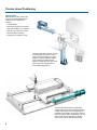
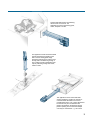
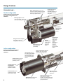
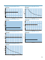
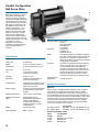
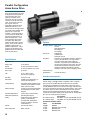
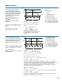
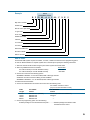
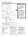
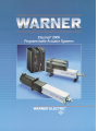
Danaher Linear has long been the
leader in ball bearing screws and
linear actuators. This new line of
Electrak programmable linear
actuators offers an expanded range of
performance in life, load carrying
capability, speed, duty cycle, accuracy
and programmability. The ball screw
actuators are rated for continuous duty
and now can operate at speeds up to
25 inches per second or position loads
up to 2000 pounds with repeatability of
0.0005". They are designed to operate
up to 50 million cycles. The controls
are Superior Electric step motor
controls. They are programmable and
a menu driven software package is
available specifically designed for
linear motion applications with terms
expressed in linear engineering units
rather than motor steps. The actuators
are also available in either the
standard parallel configuration or in a
direct drive in-line package for
applications with special size
limitations.
Contents
New!
Parallel Actuators
Handles loads up to 2000 lbs.
2 drive types
• Acme
• Ball Screw
In-line Actuators
Ideal for loads up to 1100 lbs.
2 drive types
• Acme
• Ball Screw
Controls
Applications . . . . . . . . . . . . . . . . . . . 2
Controls are complete with I/O boards,
input power cables, indexer and drive.
Design Features . . . . . . . . . . . . . . . 4
Selection Procedures . . . . . . . . . . . 8
• Full and half-step
• Micro-stepping
Performance Charts . . . . . . . . . . . 10
Parallel Configuration:
Ball Screw Drive . . . . . . . . . . . . 16
Acme Screw Drive . . . . . . . . . . . 18
In-line Configuration:
Programming
Ball Screw Drive . . . . . . . . . . . . 20
Acme Screw Drive . . . . . . . . . . . 22
High Speed . . . . . . . . . . . . . . . . 24
Software package for MS-DOS
compatible computers
Parallel or In-line Configuration:
AC Synchronous Drive . . . . . . . 26
In-line Configuration:
AC Synchronous Drive –
Hazardous Duty . . . . . . . . . . . . . 28
Programmable
Hazardous Duty . . . . . . . . . . . . . 30
Controls . . . . . . . . . . . . . . . . . . . . . 32
Motion Profiles . . . . . . . . . . . . . . . 33
Ordering Information . . . . . . . . . . . 34
Glossary . . . . . . . . . . . . . . . . . . . . 36
Application Example . . . . . . . . . . . 38
Application Worksheet . . . . . . . . . . 39
©
2000 Danaher Linear/Danaher Corp.
1
Precise Linear Positioning
Applications
Electrak 2000 actuator systems are
designed to provide efficient linear
motion control for applications
requiring:
•
•
•
•
•
•
programmability
wide speed range (up to 25 in/sec)
high load capability (up to 2000 lb)
high duty cycle rate (up to 100%)
maintenance free operation
long life (up to 50 million cycles)
These Electrak 2000 actuators are both
providing indexing functions. One is
raising the stack of plates the proper
distance to clear the platform and the
second actuator is positioning the
plates for multiple punches. This could
also be typical for a parts feeder or
other indexing applications.
This Electrak 2000 actuator is positioning a
sample between sensors to detect the moisture
content of the sample. This could typically be
positioning the sample or the sensor to monitor
thickness, texture, width, imperfections, etc. The
sensor could also be replaced by a welding
head, router, laser or water jet cutting head.
2
This Electrak 2000 actuator is positioning
valves inside an enclosure. The
application is typical of positioning gates,
valves, dampers or chutes.
This application shows the Electrak 2000
actuator positioning the heating head
that is used in sealing plastic bags.
Positioning and timing are critical to seal
the bag and to avoid burning through it.
This could be typical of applications that
require positioning tooling work heads,
cutters or drills.
This application shows an Electrak 2000
actuator positioning a table. The actuator is
mounted outside the table for the lowest
possible height of the unit. In other applications
the actuator may be mounted below the
platform and between the bearings with the
platform passing over the actuator. Multiple
units may be combined for x, y, and z axes.
3
Design Features
An inside look…
Roller thrust bearings on high load
versions for smooth operation, high load
capacity and long life. Ball bearings are
used in high speed versions.
Parallel configuration
Acme screw with self
locking operation
eliminates backdriving in
case of power failure or
motor stall.
(Shown with acme screw and gear
drive. Other configurations are
available.)
Mounting options include
clevis, front flange, side tapped
holes, and mounting feet
Anti-rotation
feature prevents
the extension
tube from
rotating.
Belt, gear or direct coupled
depending on ratio and
configuration of the actuator
Sealed motors for wash
down applications
(IP-56 rated)
Encoder
feedback option
on the motor for
closed loop
positioning
control
Holding brake
option on the
motor is also
available to
control
backdriving of
ball screw
version in
the event of
electrical power
failures.
In-line configuration
(Shown with ball screw and direct
drive. Acme screw drive is also
available.)
Holding brake option on
the motor is also available
to control backdriving of
ball screw version in the
event of electrical power
failures.
Direct coupled motor and lead
screw on all in-line actuators
provide minimal system lash.
Encoder feedback option on
the motor for closed loop
positioning control
Threaded cable entry
and watertight
connector provides
washdown capability.
Ball screw for high
load and high speed
applications
Screw terminals on size
34 and size 42 motors
provide ease of wiring.
Sealed motors for wash down
applications (IP-56 rated)
4
Roller thrust bearings on high
load versions for smooth
operation, high load capacity and
long life. Ball bearings are used in
high speed versions.
Stainless steel sxtension tube
protects against corrosion.
Rod end options
include a tapped hole,
threaded rod and
universal rod end.
Standard stroke lengths
available 2, 4, 6, 8, 12, 18, 24 inches
(for longer stroke lengths – consult factory)
Limit switches are externally
adjustable along the length of
the cover tube and can be
mounted in the T-slots on three
sides of the cover tube.
Limit switches are
externally adjustable
along the length of
the cover tube and
can be mounted in
the T-slots on three
sides of the cover
tube.
Anti-rotation
feature prevents
the extension
tube from
rotating
Wiper and O-ring provide double
protection against dirt, dust and
water contamination.
Rod end options
include a tapped hole,
threaded rod and
universal rod end.
Wiper and O-ring provide
double protection against
dirt, dust and water
contamination.
Standard stroke lengths
available 2, 4, 6, 8, 12, 18,
24 inches
Actuator Components:
Drive types
Acme screw – economical choice for
lower load, speed and duty cycle
requirements. Acme screws are selflocking by design and can not be back
driven by the load. They are
recommended for vertical applications or
other applications where back driving can
occur during loss of power. Acme screw
actuators have a 50% maximum duty
cycle rating.
Ball bearing screw – choice for higher
speed and load applications. Ball bearing
screws are highly efficient and consume
little power in converting rotary motion
into linear motion. Ball screw actuators
have a 100% duty cycle rating. Motor
power must be maintained to prevent
backdriving by the load.
Configurations
Parallel – this style of actuator allows the
broadest performance range with various
combinations of drive types and ratios,
screw types and leads, and motor sizes.
Speeds up to 15 inches per second at 20
lb. and loads up to 2000 lb. at 0.3 inches
per second define the performance limits.
A variety of mounting configurations are
available for parallel style actuators to
make installation as easy as possible.
In-line – direct drive with combinations
of motors, screws and leads provides
speeds up to 25 inches per second at 15
lb. and loads up to 1000 lb. at 0.2 inches
per second. In-line actuators are available
with front flange, trunion, side tapped
holes, or foot mounting to suit a variety of
applications.
Stainless steel extension tube
protects against corrosion.
Additional Features
Cover tube of anodized
extruded aluminum resists
corrosion, is lightweight and
allows positioning of sensors
along its length.
Continuous Duty Cycle will handle the most
rigorous applications. (Ball screw version)
Life up to 50 million cycles depending upon
screw type and load
Resolution is less than 0.0005 inches
depending on the control selected.
Ambient temperature rating of -40° to
+150°F allows a wide range of applications.
Parallel or in-line versions for different
space requirements
Load ratings up to 2,000 lb. at .3 inches per
second continuous
Speed up to 25 inches per second continuous
at 15 lbs., variable up to the maximum speed.
A constant speed regardless of load up to
load/speed rating of the actuator
Programmable positioning available with
Superior Electric controls
Software package available that is menu
driven and units are expressed in linear terms
for easier and faster programming. No need
to learn special codes
Hazardous location versions are available.
Contact the factory for explosion proof or dust
ignition proof models.
5
Rear clevis
Tapped hole
Encoder
Foot mounted
Threaded rod
Sensor
Triunion
Universal rod end
Side tapped
holes
Front flange
Brake
Mounting styles
Rod end options
Options and Accessories
Rear clevis mounting – fast and easy
connection of the actuator to a fixed
member with a pin. The clevis is on the
axis of the screw and helps to minimize
side loading in one direction. The
orientation of the rear clevis is available
in 90° increments. This style of mounting
is available only with the parallel
configuration. It is also the least rigid
mounting style.
Tapped hole – this allows the load to be
attached to the rod end by a bolt. This is
a very rigid mount and care should be
taken to avoid side loads.
Encoder – 400 or 500 line optical
encoder can be driven off of either the
lead screw or motor to provide
confirmation of actual position.
Threaded rod – this allows the load to
be attached to the rod end by a nut. This
is also a very rigid mount and care
should be taken to avoid side loads.
Brake – an electrically released, spring
set brake mounted on the motor can
control backdriving of the ball screw
actuators when the power is cut.
Universal rod end – provides two
degrees of freedom for the load. The load
is attached by a pin.
Sensors – additional magnetic sensors
can be placed on three sides of the
actuator to provide end of stroke limits or
intermediate confirmation of position.
Trunion mounting – provides a pivot
point on the body of the actuator. Parallel
pins are attached to the T-slots on each
side of the actuator.
Mounting feet – are used to raise the
actuator off of the mounting surface while
keeping it parallel to the surface.
Mounting feet rigidly mount the actuator
to the surface.
Side tapped holes – drilled and tapped
holes are in the side of the actuator to
rigidly mount the actuator to the surface.
This option with either the tapped hole or
threaded rod provides the most accurate
and repeatable performance for the
actuator.
Front flange – this allows the actuator to
be mounted by the front flange on the
cover tube. This is also a rigid mounting
system and does not permit any side to
side motion of the actuator. This is not
recommended for over 12" stroke length
in horizontal applications due to the over
hanging load.
6
SLO
-SYN
2000
SLO
-SYN
2000
®
®
Diskette
For SS2000
series controls
SS2000I
and
SS2000D6
Cable
Controls
Programming options
Cable – a cable which interconnects
the control and actuator is required.
It is available in 10, 25, or 50 foot
lengths.
SloSyn 2000 control is available as a
separate indexer and driver. It is switch
selectable between full, half or
microstepping and is designed for use
with size 34 three stack motors (BI93 or
BP93) and size 42 motors (BI12). Current
output is selectable on the drive portion
of the control up to 6 amps. (Size 34
motors require 3 amps, size 42 motors
require 6 amps). The I/O wire directly to
the control.
Software diskette packet – this diskette
allows the control to be programmed
directly from an IBM® compatible
personal computer. It provides the
handshake, is menu driven and displays
in linear units rather than steps. A 10 foot
cable is provided to connect the
computer to the control. The software
diskette packet is included with the
control.
Acme Screw Models
Maximum Dynamic
Load (lbs.)
Ball Screw Models
150
250
300
1000
500
700
1000
2000
250
400
500
440
1100
9
6
4
1.75
7
5
4
1.9
17
14
12
25
10
Drive Ratio
1.0:1
1.5:1
2.0:1
5.0:1
1.0:1
1.5:1
2.0:1
5.0:1
1.0:1
1.5:1
2.0:1
1.0:1
1.0:1
Screw Lead
0.2
0.2
0.2
0.2
0.2
0.2
0.2
0.2
0.5
0.5
0.5
0.5
0.2
**Step Motor
Frame Size
93
93
93
93
93
93
93
93
93
93
93
12
12
Maximum Speed
(in./sec.)
Control Required
SS2000I and
SS2000D6
SS2000I and
SS2000D6
SS2000I and
SS2000D6
SS2000I and
SS2000D6
* Maximum speeds are not possible at maximum rated dynamic load.
Consult the speed / load charts on pages 10-15 for actual performance ratings.
** 93 = size 34 triple stack
12 = size 42 (in line only)
7
Selection Procedures
FRICTION FORCE =
Information needed:
Max.load = ______ lbs
Max speed = _____ inches per second
Duty cycle = _____ % on time verses
off time
Stroke length = ___ inches
Life = ___________ cycles, inches,
hours
Acceleration = ____ inches per second2
Resolution = _____ inches
Back driving load = _____yes _____no
Weight (lbs) x coefficient of friction of
the bearing supports (µ)
Typical µ = .001 for linear ball ways
= .005 for roller way bearings
= .005 for ball bearing splines
WEIGHT =
STEP 5
Select mounting options: choose the
mounting method for the actuator bodyrear clevis (not available on in-line
version), front flange, trunion, side
tapped holes or mounting feet. These
options are shown below and described
on page 6.
Weight of object being lifted*
*In horizontal applications the weight of
the load must be totally supported by
linear ways or bushings, the actuator
should push and pull the load only. The
actuator should not be side loaded.
Rear clevis
STEP 3
STEP 1
Determine actuator performance
characteristics: determine the load,
speed, duty cycle, life and stroke length.
If the application requires load holding in
the event of power failure there are two
reliable solutions: 1) A load holding brake
can be used on ball screws to prevent
backdriving in the event of a power
failure while providing the superior
performance of a ball screw. Warning! A
load holding brake will not prevent a
ball screw actuator from backdriving
if it is overloaded and stalls. 2) Acme
screws can be selected. Acme screws
are a lower cost alternative but do limit
actuator load, speed, duty cycle and life.
Acme screws will not backdrive even if
an actuator is overloaded and stalls.
Ball bearing screw
Acme screw
Select the actuator which has the
optimum load and extension speed for
your application based on the
performance curves on pages 10 and 11.
Several actuators may meet your
requirements. Acme screw units are
generally less expensive but are limited
to a maximum of 50% duty cycle. If you
are unsure about your actual load/speed
requirements you may want to limit the
selection to actuators which provide
sufficient reserve capacity. Warning! Do
not exceed the load/speed
performance curves. Exceeding the
curve will cause the motor to stall and
produce zero torque. This could result
in backdriving the actuator.
Use on parallel
models only
Front flange
Trunion
To estimate the life of an actuator in your
particular application please refer to the
lead screw life chart on page 36.
Note: All load and speed curves
represent the typical performance based
on the appropriate Superior Electric
controls. The use of other controls may
reduce the performance of the actuators
significantly.
Side tapped holes
STEP 4
STEP 2
Calculate Total Force (lbs)
TOTAL FORCE =
Acceleration Force + Friction Force +
Weight
Note: In horizontal applications the
weight component of the total force
should be zero.
ACCELERATION FORCE =
Determine actuator configuration: If
the load is less than 1000 pounds
determine the desired actuator
configuration- parallel or in-line. If the
load is above 1000 pounds the only
configuration available is parallel. If an
actuator is available as an in-line or
parallel version both part numbers will be
shown on the performance charts.
Parallel
Mass x Acceleration
weight
(lbs)
velocity (in/sec.)
1 ft
________
x ______________ x ____
2
time to speed (sec)
12 in.
32.2 ft/sec
In-line
8
Mounting feet
STEP 6
STEP 8
STEP 9
Select rod end
options: choose the
type of connection you
want on the extension
tube 1/2 – 20 UNF
tapped hole 1.37 min
deep, 1/2 – 20 UNF
threaded rod .75 max
long or .500 diameter
spherical rod end.
Further information
about the options is
available on page 6.
Select control: Choose from the
Superior Electric controls described on
page 32. The SS2000D6 and SS2000I is
used with all BI93, BP93 and BI12
actuators. The micro-stepping controls
will provide 0.0005 inches resolution in
any screw/drive combination. The full
and half-step control will provide the
resolution indicated in the following chart.
Gear ratios of 5:1. 10:1 or 20:1 will
provide 0.0005 inches resolution with
any screw lead and either control.
Verification
controls should
be selected when
an encoder is
chosen as an
actuator option.
Select cable between actuator and
control: If you are using one of the
Superior Electric controls from the
catalog select a cable to run from the
control to the actuator. It is available in
10, 25, or 50 foot lengths.
STEP 7
SLO-
SYN
2000
Part Numbers
SLO-
SYN
2000
Select options and
accessories: choose
the options and
accessories that you
want including an
optical encoder driven
either off the motor or
the lead screw,
additional sensors for
use as over travel limit
switches or a spring set
brake mounted on the
motor. Choose a 400
line encoder when
using a full or half-step
control and a 500 line
encoder when using a micro-stepping
control. Be sure and select a verification
control when using an encoder.
See page 34 for explanation of catalog
numbering system.
Cable
Length
For
SS2000D6
Control
®
®
SS2000D6 &
SS2000I
Resolution
Full-step
Gear
Ratio
.200
.500
1:1
1.5:1
2:1
.0010
.0006
.0005
.0025
.0017
.0013
Screw Lead
Half-step
Gear
Ratio
.200
.500
1:1
1.5:1
2:1
.0005
.0005
.0005
.0013
.0008
.0006
Screw Lead
Each control comes with an I/O
terminal board. The I/O terminal
board allows the limit switch signals
to be fed into the PAC 440 control
by a 25 pin “D” connector with ribbon
cable which is provided. The terminal
strip plugs directly into the SS2000I.
10 ft.
included
25 ft.
B216022-032
50 ft.
B216022-033
Encoder feedback cable (for use only
with verification controls and encoder
feedback option.)
10 ft.
(included with
SS2000I-V)
25 ft.
250-9014
STEP 10
A software package for the SS2000
control is included with the SS2000I. It
allows programming the control through
the serial (RS232) port of an IBM®
compatible personal computer. The
program is supplied on a diskette and is
completely menu driven, so it is easy to
use and does not require memorizing
complicated instructions. It also allows
programming in linear units instead of
steps, degrees or revolutions. A 10 foot
long cable with 9 pin “D” connectors on
each end is included to connect the
computer to the control for programming.
A 9 pin to 25 pin adapter is included for
those computers with 25 pin serial ports.
9
Performance Charts
Detailed charts for each
actuator are shown on
pages 12–15.
10
Electrak 2000 Performance
Acme Screws Less than 250 lb Force
9
BP9301-A65
(BI9301-A65)
Speed (in/sec)
8
BP9315-A65
7
6
5
4
3
2
1
0
40
0
80
120
160
200
240
Total Force (lb)
5.0
Electrak 2000 Performance
Acme Screws Less than 1000 lb Force
4.5
BP9302-A65
BP9305-A65
4
Speed (in/sec)
When selecting the correct
actuator be sure that you do
not exceed the load/speed
curve. If the load/speed
curve is exceeded the motor
produces no torque and the
load may backdrive the
screw, or the control may
lose steps not knowing the
exact position of the load.
Using the motion profiles on
page 30 you can calculate
the acceleration, top speed
and deceleration needed to
accomplish a particular
move within a set time
frame. Be sure that the
acceleration and
deceleration rates that you
choose do not cause you to
exceed the load/speed
curve. If you wish to
estimate the life of an
actuator in your particular
application please refer to
the lead screw life chart on
page 36.
3.5
3
2.5
2
1.5
1
0.5
0
0
100
200
300
400
500
Total Force (lb)
10
600
700
800
900
1000
20
Electrak 2000 Performance
Ball Screws Less than 400 lb Force
BP9301-B72
(BI9301-B72)
BP9315-B72
BI1201-B72
BIA101-B72
Speed (in/sec)
15
and
BPA101-B72
BIA301-B72
BIA101-B75
BI1201-B11
BI1201-B72
BPA102-B72
10
5
0
0
50
100
150
200
250
300
350
400
Total Force (lb)
12
Electrak 2000 Performance
Ball Screws Less than 1100 lb Force
BP9302-B72
BP9315-B75
BP9301-B75
(BI9301-B75)
BIA301-B75
BI1201-B75
BPA105-B72
Speed (in/sec)
10
8
6
4
2
0
0
100
200
300
400
500
600
700
800
900
1000
1100
Total Force (lb)
5
Electrak 2000 Performance
Ball Screws Less than 2000 lb Force
4.5
BP9302-B75
BP9305-B75
BPA105-B75
4
Speed (in/sec)
3.5
3
2.5
2
1.5
1
0.5
0
0
200
400
600
800
1000
Total Force (lb)
1200
1400
1600
1800
2000
11
Performance Charts
When selecting an actuator be sure to choose an actuator
whose performance curve exceeds your requirements with a
margin of reserve. Warning! If you exceed the load speed
curves the actuator will stall and may backdrive! The
control may lose the position of the load and should be reset.
Acme Screws Less than 1000 Lb. Force
BP9305-A65
2
1.5
Speed (in/sec)
These charts show the detailed performance of each actuator.
When using the charts please note that the values for load
and speed axes are different for each actuator chart. If you
want to easily compare the performance of various actuators
please refer to the charts on pages 10 and 11. The individual
performance charts are arranged in the same order as on the
composite charts on pages 10 and 11.
1
0.5
If you wish to estimate the life of an actuator in your particular
application please refer to the lead screw life chart on page 36.
0
0
100
200
300
400
500
600
700
800
900
1000
Total Force (lb)
Acme Screws Less than 250 Lb. Force
Ball Screws Less than 400 Lb. Force
BP9301-A65 (BI9301-A65)
BP9301-B72 (BI9301-B72)
20
10
9
8
Speed (in/sec)
Speed (in/sec)
15
7
6
5
10
4
3
5
2
1
0
0
0
25
50
75
100
125
150
0
50
100
150
Total Force (lb)
200
250
300
Total Force (lb)
Acme Screws Less than 250 Lb. Force
Ball Screws Less than 400 Lb. Force
BP9315-A65
BP9315-B72
7
20
15
5
Speed (in/sec)
Speed (in/sec)
6
4
3
10
2
5
1
0
0
0
25
50
75
100
125
150
175
200
225
250
0
50
100
Total Force (lb)
150
200
250
300
350
400
Total Force (lb)
Acme Screws Less than 1000 Lb. Force
Ball Screws Less than 400 Lb. Force
BP9302-A65
BI1201-B72
4.5
30
4
25
Speed (in/sec)
Speed (in/sec)
3.5
3
2.5
2
1.5
20
15
10
1
5
0.5
0
0
0
50
100
150
Total Force (lb)
12
200
250
300
0
100
200
Total Force (lb)
300
400
Ball Screws Less than 400 Lb. Force
Ball Screws Less than 400 Lb. Force
BIA101-B72
BI1201-B72
1
0.9
20
0.7
Speed (in/sec)
Speed (in/sec)
0.8
0.6
0.5
0.4
15
10
0.3
5
0.2
0.1
0
0
0
25
50
75
100
125
150
175
0
200
50
100
200
Ball Screws Less than 400 Lb. Force
Ball Screws Less than 400 Lb. Force
BIA101-B75
BPA101-B72
1
1
0.9
0.9
0.8
0.8
0.7
0.7
0.6
0.5
0.4
250
0.6
0.5
0.4
0.3
0.3
0.2
0.2
0.1
0.1
0
0
0
50
100
150
200
250
300
350
400
0
25
50
75
Total Force (lb)
100
125
150
175
200
350
400
Total Force (lb)
Ball Screws Less than 400 Lb. Force
Ball Screws Less than 400 Lb. Force
BPA102-B72
BIA301-B72
1
1
0.9
0.9
0.8
0.8
0.7
0.7
Speed (in/sec)
Speed (in/sec)
150
Total Force (lb)
Speed (in/sec)
Speed (in/sec)
Total Force (lb)
0.6
0.5
0.4
0.6
0.5
0.4
0.3
0.3
0.2
0.2
0.1
0.1
0
0
0
25
50
75
100
125
150
175
200
225
250
0
50
100
150
200
250
300
Total Force (lb)
Total Force (lb)
Ball Screws Less than 400 Lb. Force
BI1201-B11
45
40
Speed (in/sec)
35
30
25
20
15
10
5
0
0
50
100
150
200
250
Total Force (lb)
13
Performance Charts
16
Ball Screws Less than 1100 Lb. Force
Ball Screws Less than 1100 Lb. Force
BP9302-B72
BIA301-B75
1
0.9
0.8
Speed (in/sec)
Speed (in/sec)
12
8
0.7
0.6
0.5
0.4
0.3
4
0.2
0.1
0
0
0
50
100
150
200
250
300
350
400
450
500
0
100
200
300
Total Force (lb)
8
400
500
600
700
Total Force (lb)
Ball Screws Less than 1100 Lb. Force
Ball Screws Less than 1100 Lb. Force
BP9301-B75 (BI9301-B75)
BI1201-B75
10
8
Speed (in/sec)
Speed (in/sec)
6
4
6
4
2
2
0
0
0
50
100
150
200
250
300
350
400
450
500
0
100
200
300
Total Force (lb)
8
400
500
600
700
Total Force (lb)
Ball Screws Less than 1100 Lb. Force
Ball Screws Less than 1100 Lb. Force
BP9315-B75
BPA105-B72
1
0.9
0.8
Speed (in/sec)
Speed (in/sec)
6
4
0.7
0.6
0.5
0.4
0.3
2
0.2
0.1
0
0
0
100
200
300
400
Total Force (lb)
14
500
600
700
0
100
200
300
400
Total Force (lb)
500
600
700
800
5
Ball Screws Less than 2000 Lb. Force
Ball Screws Less than 2000 Lb. Force
BP9302-B75
BPA105-B75
1
4
0.8
3.5
0.7
Speed (in/sec)
0.9
Speed (in/sec)
4.5
3
2.5
2
0.6
0.5
0.4
1.5
0.3
1
0.2
0.5
0.1
0
0
0
200
400
600
800
1000
0
200
400
600
800
1000
1200
1400
1600
1800
2000
Total Force (lb)
Total Force (lb)
Ball Screws Less than 2000 Lb. Force
2
BP9305-B75
Speed (in/sec)
1.5
1
0.5
0
0
200
400
600
800
1000
1200
1400
1600
1800
2000
Total Force (lb)
15
Parallel Configuration
Ball Screw Drive
Ball screw actuators are used in
applications that require duty
cycles up to 100%, high load or
high speed capability. Electrically
released brakes can be used to
prevent back-driving of the screw
with power off. Ball screw units
are available in either in-line or
parallel configurations. In-line
versions are direct drive and
parallel versions are either belt
driven or gear driven. Flange,
clevis, foot, and side tapped
holes provide versatile actuator
mounting and the three rod end
options provide either a very rigid
connection for precise
applications or a compliant
connection for applications that
require multiple degrees of
freedom.
Specifications
Dynamic Load:
up to 2000 lb at .3 in/sec
Static Load:
up to 2000 lb
Speed:
up to 17 inches/sec at 40 lbs
Acceleration:
up to 50 inches/sec2 at no load
Duty Cycle:
up to 100%
Life:
up to 50 million cycles
(use chart on page 36)
End Play:
0.010 inch max.
Resolution:
0.0005 inches (depending on
screw lead and control)
Limit Switches:
home limit switch standard, other
switches may be added on three
sides of the cover tube
Stroke Lengths:
2,4,6,8,12,18,24 inches standard
(consult factory for other stroke
lengths)
Ambient Temperature:
-40° to 150° F (-40° to 65°C)
Washdown Protected:
(IP56)
standard (direct spray
applications require optional
venting, contact factory.
For washdown applications
requiring a brake or encoder,
contact factory.)
Motors:
size 34 step motors
Motor amperage:
BP93 3 amps
Options
Mounting options: Rear clevis
Trunion
Side tapped holes
Mounting feet
Front flange
Rod ends:
Tapped hole
Threaded rod
Spherical rod end
Brake:
Load holding brakes are available mounted on
the motor to prevent back driving the load with
the power off. The brake is spring set and
electrically released to prevent load movement
during power off conditions.
Encoders:
Encoders are available mounted on either the
motor or the lead screw. The output of the
encoder is either 400 or 500 pulses per
revolution. The pulses per inch depends on
the gear ratio and lead of the screw. The 400
line encoder should be used with a full and
half-step control and the 500 line encoder
should be used with a micro-stepping control.
Hazardous duty
applications:
Contact the factory
Actuator Accessories
Sensors
Sensor rating is 10W @ 120VAC or 200VDC. A N.O. (normally
open) sensor is provided with the actuator for home position.
Channels are manufactured on three sides of the cover tube to
accept additional sensors. The sensors are simply inserted in the
end of the channel and moved to the desired position. Set screws
secure the sensor in place. The leads from the sensor are then
wired to the I/O board supplied with the control. The SS2000
controls do not require diodes on inputs and can accept either
N.O. or N.C. sensor inputs but not both.
N.O. without diode
N.C. without diode
Part Number
840-9005 (for use with SS2000 control)
840-9008 (for use with SS2000 control)
Control to Actuator cable
Cable
Length
10 feet
25 feet
50 feet
16
For SS2000D6
Control
B216022-031 (included)
B216022-032
B216022-033
Dimensions
Electrical Stroke + 9.951 +.067
Electrical Stroke + 9.751 +.067
Front Flange Plate
(see detail below)
A
(BP93 Actuator)
1/2-14 NPT (2)
Use with Encoder
2.562 Min.
2.163 Min.
.345 Min.
.23 Min.
2.14
Max.
.750 Ref.
3.385
Dia. Max.
.44 Min. (Typ)
.550 Ref.
1/2-20 UNF 2B Thd.
1.37 Min. Dp.
.625 Ref. Typ.
.060 R. Ref.
1.29 Max.
4.76 Min.
Encoder or Brake
Mounted on Screw
2.225
2.35 Max.
.750 Wrench
Flat (Typ.)
1.401 Dia.
Max. (Typ.)
.750 Ref. (2)
1.50 +.015
Optional – Trunion Mounting
Electrical Stroke + 6.742 +.050
1/2-20 Internal Thd. Rod End
2.734 +.032
2, 4, 6, 8, 12, 18, 24
Stroke Electrical
(Typical)
Retracted Length Electrical = Electrical Stroke + 11.171
1/2-20 Internal Thd. Rod End
.12 Max. to Mechanical
Stop (Typ.)
Retracted Length Electrical = Electrical Stroke + 11.921
1/2-20 External Thd. Rod End
.44 Min.
2.225
.12 Max. to Mechanical
Stop (Typ.)
Stroke Electrical
.74 Min.
1/2-20 UNF 2A Thd.
.625 Ref.
5.75 +.025
Retracted Length Electrical = Electrical Stroke + 12.846
1/2-20 External Thd. Rod End
Stroke Electrical
.55 Max.
.66 R. Max.
1.10
.501 +.002 Dia.
Actuator
Description
Dim.
Motors without brake or encoder
Motors with brake or encoder
9.476 max.
11.796 max.
1.000 +.005
A
BP93
.58 Min.
.635 Max.
.506 +.003 Min.
6.000 +.080
Trunion Mtg.
3.28 Max.
2.90 Max.
1.64 Max.
1.00 +.01
Typ.
+.005
-.001
3.875 +.005
1.938 +.005
.340 +.005
Dia.(4)
2.907 6.08
Ref. Max.
3.000
Ref.
2.984
Ref.
1.00
Dia. Typ.
1.500
Ref.
1.095 +.005
2.190 +.005
1.51
Max.
1/4-20 UNC 2B Thd.
.375 Dp. (2)
Side Tapped Holes
.2.313
Ref.
1/4-20 UNC 2B Thd.
.375 Dp. 2
Side Tapped Holes
2.25 +.015
4.625 Ref.
.750 Ref. (2)
1.51 Max.
3.01 Max.
Rear Foot Mounting
.413 +.005 Dia. (4)
Front Flange Plate Mounting
.625 +.005 (Typ.)
.375 Ref.
4.00 +.01
Front Foot Mounting
17
Parallel Configuration
Acme Screw Drive
Acme screw actuators are used
for applications that require no
more than 50% duty cycle,
loads up to 1000 lb. at 0.4
inches per second or speeds
up to 8.5 inches per second at
10 lb. Acme screw units are
also a good choice for
applications that must not be
allowed to back drive. The
acme screw has enough friction
to hold the load in position with
power off or a motor stall
condition. The life expectancy
of an acme screw will be less
than that of a ball screw in a
particular application. Acme
screw units are also a lower
cost option than ball screw
units for similar load or speed
ratings. Acme screw units are
available in either in-line or
parallel configurations. In-line
versions are direct drive and
parallel versions are either belt
driven or gear driven.
Specifications
Options
Mounting options: Rear clevis
Trunion
Side tapped holes
Mounting feet
Front flange
Rod ends:
Tapped hole
Threaded rod
Spherical rod end
Encoders:
Encoders are available mounted on either the
motor or the lead screw. The output of the
encoder is either 400 or 500 pulses per
revolution. The pulses per inch depends on
the gear ratio and lead of the screw. The 400
line encoder should be used with a full and
half-step control and the 500 line encoder
should be used with a micro-stepping control.
Hazardous duty
applications:
Contact the factory
Dynamic Load:
up to 1000 lb at .4 in/sec
Static Load:
up to 1000 lb
Speed:
up to 8.5 inches/sec at 10 lbs
Acceleration:
up to 25 inches/sec2 at no load
Duty Cycle:
up to 50%
Life:
up to 1 million cycles
(see chart on page 36)
End Play:
0.010 inch max.
Actuator Accessories
Resolution:
0.0005 inches (depending on
screw lead and control)
Sensors
Limit Switches:
home limit switch standard, other
switches may be added on three
sides of the cover tube
Stroke Lengths:
2,4,6,8,12,18,24 inches standard
(consult factory for other stroke
lengths)
Ambient Temperature:
-40° to 150° F (-40° to 65°C)
Washdown Protected:
(IP56)
standard (direct spray
applications require optional
venting, contact factory.
For washdown applications
requiring a brake or encoder,
contact factory.)
Motors:
size 34 step motors
Motor amperage:
BP93 3 amps
18
Sensor rating is 10W @ 120VAC or 200VDC. A N.O. (normally
open) sensor is provided with the actuator for home position.
Channels are manufactured on three sides of the cover tube to
accept additional sensors. The sensors are simply inserted in the
end of the channel and moved to the desired position. Set screws
secure the sensor in place. The leads from the sensor are then
wired to the I/O board supplied with the control. The SS2000
controls do not require diodes on the inputs and can accept either
N.O. or N.C. sensor inputs but not both.
Part Number
N.O. without diode
840-9005 (for use with SS2000 control)
N.C. without diode
840-9008 (for use with SS2000 control)
Control to Actuator cable
Cable
Length
10 feet
25 feet
50 feet
For SS2000D6
Control
B216022-031 (included)
B216022-032
B216022-033
Dimensions
Electrical Stroke + 8.871 +.067
Electrical Stroke + 8.671 +.067
Front Flange Plate
(see detail below)
A
(BP93 Actuator)
1/2-14 NPT (2)
Use with Encoder
2.562 Min.
2.163 Min.
.345 Min.
.20 Min.
2.14
Max.
.750 Ref.
3.385
Dia. Max.
.44 Min. (Typ)
.550 Ref.
1/2-20 UNF 2B Thd.
1.37 Min. Dp.
.625 Ref. Typ.
.060 R. Ref.
1.29 Max.
4.76 Min.
Encoder Mounted
on Screw
2.225
2.35 Max.
1.213 Dia.
Max. (Typ.)
.750 Ref. (2)
1.50 +.015
Optional – Trunion Mounting
Electrical Stroke + 5.662 +.050
Foot Mounting
2.734 +.032
2, 4, 6, 8, 12, 18, 24
Stroke Electrical
(Typical)
Retracted Length Electrical = Electrical Stroke + 10.092
1/2-20 Internal Thd. Rod End
.12 Max. to Mechanical
Stop (Typ.)
.12 Max. to Mechanical
Stop (Typ.)
2.225
Retracted Length Electrical = Electrical Stroke + 10.842
1/2-20 External Thd. Rod End
.750 Wrench
Flat (Typ.)
Stroke Electrical
.44 Min.
.74 Min.
1/2-20 UNF 2A Thd.
.625 Ref.
5.75 +.025
Stroke Electrical
Retracted Length Electrical = Electrical Stroke + 12.846
1/2-20 External Thd. Rod End
.55 Max.
.66 R. Max.
1.10
.501 +.002 Dia.
Actuator
Description
Dim.
Motors without brake or encoder
Motors with brake or encoder
9.476 max.
11.796 max.
1.000 +.005
A
BP93
.58 Min.
.635 Max.
6.000 +.080
Trunion Mtg.
2.23 Max.
3.28 Max.
1.00 +.01
Typ.
1.64 Max.
1.00 +.000
-.001
.00
Dia. Typ.
3.875 +.005
1
1.938 +.005
.340 +.005
Dia.(4)
2.907 6.08
Ref. Max.
3.000
Ref.
2.984
Ref.
1.095 +.005
2.190 +.005
1.51
Max.
.50 +.01
.750 Ref. (2)
1.500
Ref.
1/4-20 UNC 2B Thd.
.375 Dp. (2)
Side Tapped Holes
Rear Foot Mounting
.413 +.005 Dia. (4)
1/4-20 UNC 2B Thd.
.250 Dp. (2)
Side Tapped Holes
2.250 +.015
4.625 Ref.
Front Flange Plate Mounting
1.51 Max.
3.01 Max.
2.313
Ref.
.625 +.005 (Typ.)
.375 Ref.
4.00 +.01
Front Foot Mounting
19
In-line Configuration
Ball Screw Drive
In-line ball screw actuators
are used in applications that
require duty cycles up to
100%, loads up to 1100 lbs.
at 0.2 inches per second, or
speeds up to 25 inches per
second at 15 lbs.
Electrically released brakes
are required to prevent
back-driving of the screw
with power off. In-line
versions are direct drive and
are available in three load
and speed versions.
Flange, foot, trunion and
side tapped holes provide
versatile actuator mounting
and the three rod end
options provide either a very
rigid connection for precise
applications or a compliant
connection for applications
that require multiple
degrees of freedom.
Specifications
Options
Mounting options: Trunion
Side tapped holes
Mounting feet
Front flange
Rod ends:
Tapped hole
Threaded rod
Spherical rod end
Brake:
Load holding brakes are available mounted on
the motor to prevent back driving the load with
the power off. The brake is spring set and
electrically released to prevent load movement
during power off conditions.
Encoders are available mounted on the motor.
The output of the encoder is either 400 or 500
pulses per revolution. The pulses per inch
depends on the lead of the screw. The 400 line
encoder should be used with a full and halfstep control and the 500 line encoder should
be used with a micro-stepping control.
(In-line actuators can not have both a brake
and an encoder)
Encoders:
Dynamic Load:
up to 1100 lb at 0.2 in/sec
Static Load:
up to 1100 lb
Speed:
up to 25 inches/sec at 15 lbs
Acceleration:
up to 50 inches/sec2 at no load
Duty Cycle:
up to 100%
Life:
up to 50 million cycles
(see chart on page 36)
End Play:
0.010 inch max.
Resolution:
0.0005 inches(depending on
screw lead and control)
Actuator Accessories
Limit Switches:
home limit switch standard, other
switches may be added on three
sides of the cover tube
Sensors
Stroke Lengths:
2,4,6,8,12,18,24 inches standard
(consult factory for other stroke
lengths)
Ambient Temperature:
-40° to 150° F (-40° to 65°C)
Washdown Protected:
(IP56)
standard (direct spray
applications require optional
venting, contact factory.
For washdown applications
requiring a brake or encoder,
contact factory.)
Motors:
size 34 or 42 step motors
Motor amperage:
BI93 3 amps
BI12 6 amps
20
Hazardous duty
applications:
Contact the factory
Sensor rating is 10W @ 120VAC or 200VDC. A N.O. (normally
open) sensor is provided with the actuator for home position.
Channels are manufactured on three sides of the cover tube to
accept additional sensors. The sensors are simply inserted in the
end of the channel and moved to the desired position. Set screws
secure the sensor in place. The leads from the sensor are then
wired to the I/O board supplied with the control. The SS2000
controls do not require diodes on inputs and can accept either
N.O. or N.C. sensor inputs but not both.
N.O. without diode
N.C. without diode
Part Number
840-9005 (for use with SS2000 control)
840-9008 (for use with SS2000 control)
Control to Actuator cable
Cable
Length
10 feet
25 feet
50 feet
For SS2000D6
Control
B216022-031 (included)
B216022-032
B216022-033
Dimensions
Retracted Length Electrical = Electrical Stroke + 11.410
1/2-20 Internal Thd. Rod End
.12 Max. to
Mechanical Stop (Typ.)
Electrical Stroke
+ 10.207 +.060
Electrical Stroke
+ 10.007 +.060
A
(BP93 Actuator)
.12 Max. to
Mechanical
Stop (Typ.)
2, 4, 6, 8, 12, 18, 24
Stroke Electrical
(Typical)
Front Flange Plate
(see detail below)
B
(BI12 Actuator)
1/2-14 NPT
5.00 Min.
1/2-14 NPT
1/2-20 UNF 2B Thd.
1.37 Min. Dp.
.750 Ref.
.550 Ref.
1.401 Dia. Max. (Typ.)
.750 Wrench
Flat (Typ.)
1.29 Max.
1.50 +.015
(2)
2.35 Max.
.625 Ref. (Typ.)
.44 Min. (Typ)
.060 R. Ref.
3.385 Dia. Max.
Optional – Trunion Mounting
4.260 Dia. Max.
3.333 +.030
Electrical Stroke + 6.399 +.045
Foot Mounting
Retracted Length Electrical = Electrical Stroke + 12.160
1/2-20 Internal Thd. Rod End
Stroke Electrical
1/2-20 UNF 2A Thd.
.74 Min.
Retracted Length Electrical = Electrical Stroke + 12.510
.50 I.D. Spherical Ball Rod End
Stroke Electrical
1.10
Actuator
Description
Dim.
7.182 max.
9.502 max.
8.322 max.
A
BI93
Motors without brake or encoder
Motors with brake or encoder
B
BI12
Motors without brake or encoder
.66 R. Max.
.501 +.002 Dia.
.635
Max.
6.000 +.080
Trunion Mtg.
4.27 Max.
Size 42 Motor
3.52 Max.
Size 34 Motor
3.875
1.00 +.01
Dia. Typ.
+.005
1.938 +.005
2.907
Ref.
4.27 3.52
Max. Max.
.340 +.005
Dia.(4)
1.095 +.005
3.000
Ref.
2.190 +.005
1.51
Max.
1/4-20 UNC 2B Thd.
.375 Dp. (2)
Side Tapped Holes
.750 Ref. (2)
1/4-20 UNC 2B Thd.
.375 Dp. 2
Side Tapped Holes
Rear Foot Mounting
.413 +.005 Dia. (4)
2.250 +.025
4.625 Ref.
Front Flange Plate Mounting
.625 +.005 (Typ.)
+.000
1.000 -.001
Dia. Typ.
1.500
Ref.
.50 +.01
.375 Ref.
4.00 +.01
Front Foot Mounting
21
In-line Configuration
Acme Screw Drive
In-line Acme screw
actuators are used for
applications that require no
more than 50% duty cycle,
loads up to 150 lbs. at 3
inches per second or
speeds up to 8.5 inches per
second at 8 lbs. Acme
screw units are also a good
choice for applications that
must not be allowed to back
drive. The acme screw has
enough friction to hold the
load in position with power
off or a motor stall
condition. Acme screw
units are also a lower cost
option than ball screw units
for similar load or speed
ratings. In-line versions are
directly coupled between
the motor and lead screw.
Specifications
Options
Mounting options: Trunion
Side tapped holes
Mounting feet
Front flange
Rod ends:
Tapped hole
Threaded rod
Spherical rod end
Encoders:
Encoders are available mounted on the motor.
The output of the encoder is either 400 or 500
pulses per revolution. The pulses per inch
depends on the lead of the screw. The 400
line encoder should be used with a full and
half-step control and the 500 line encoder
should be used with a micro-stepping control.
Dynamic Load:
up to 150 lb at 3 in/sec
Static Load:
up to 1000 lb
Speed:
up to 8.5 inches/sec at 8 lbs
Acceleration:
up to 25 inches/sec2 at no load
Duty Cycle:
up to 50%
Life:
up to 1 million cycles
(see chart on page 36)
Actuator Accessories
End Play:
0.010 inch max.
Sensors
Resolution:
0.0005 inches(depending on
screw lead and control)
Limit Switches:
home limit switch standard, other
switches may be added on three
sides of the cover tube
Stroke Lengths:
2,4,6,8,12,18,24 inches standard
(consult factory for other stroke
lengths)
Sensor rating is 10W @ 120VAC or 200VDC. A N.O. (normally
open) sensor is provided with the actuator for home position.
Channels are manufactured on three sides of the cover tube to
accept additional sensors. The sensors are simply inserted in the
end of the channel and moved to the desired position. Set screws
secure the sensor in place. The leads from the sensor are then
wired to the I/O board supplied with the control. The SS2000
controls do not require diodes on inputs and can accept either
N.O. or N.C. sensor inputs but not both.
Ambient Temperature:
-40° to 150° F (-40° to 65°C)
Washdown Protected:
(IP56)
standard (direct spray
applications require optional
venting, contact factory.
For washdown applications
requiring a brake or encoder,
contact factory.)
Motors:
size 34 step motors
Motor amperage:
BI93 3 amps
22
Hazardous duty
applications:
Contact the factory
Part Number
N.O. without diode 840-9005 (for use with SS2000 control)
N.C. without diode 840-9008 (for use with SS2000 control)
Control to Actuator cable
Cable
Length
10 feet
25 feet
50 feet
For SS2000D6
Control
B216022-031 (included)
B216022-032
B216022-033
Dimensions
Retracted Length Electrical = Electrical Stroke + 10.35
1/2-20 Internal Thd. Rod End
.12 Max. to
Mechanical Stop (Typ.)
Electrical Stroke
+ 9.127 +.060
2, 4, 6, 8, 12, 18, 24
Stroke Electrical
(Typical)
.12 Max. to
Mechanical
Stop (Typ.)
Electrical Stroke
+ 8.927 +.060
Front Flange Plate
(see detail below)
A
(BP93 Actuator)
5.00 Min.
1/2-14 NPT
.750 Ref.
1/2-20 UNF 2B Thd.
1.37 Min. Dp.
.550 Ref.
1.213 Dia.
Max. (Typ.)
.750 Wrench
Flat (Typ.)
1.29 Max.
1.50 +.015
(2)
2.35 Max.
.625 Ref. (Typ.)
.44 Min. (Typ)
.060 R. Ref.
3.385 Dia. Max.
Optional – Trunion Mounting
Electrical Stroke + 6.399 +.045
Foot Mounting
3.333 +.030
Retracted Length Electrical = Electrical Stroke + 12.160
1/2-20 Internal Thd. Rod End
Stroke Electrical
1/2-20 UNF 2A Thd.
.44 Miin.
.74 Min.
.625 Ref.
Retracted Length Electrical = Electrical Stroke + 11.450
.50 I.D. Spherical Ball Rod End
Stroke Electrical
1.10
Actuator
A
BI93
Description
Dim.
Motors without brake or encoder
Motors with brake or encoder
7.182 max.
9.502 max.
.66 R. Max.
.501 +.002 Dia.
.635
Max.
6.000 +.080
Trunion Mtg.
1.938
2.14
Max.
3.52
Max.
+.005
.340 +.005
Dia.(4)
1.500
Ref.
2.190 +.005
4.625 Ref.
Front Flange Plate Mounting
.750 Ref. (2)
+.005
(Typ.)
Rear Foot Mounting
.413 +.005 Dia. (4)
1.000 +.000
-.001
Dia. Typ.
1.095 +.005
3.000
Ref.
1/4-20 UNC 2B Thd.
.375 Dp. (2)
Side Tapped Holes
.625
2.23 Max.
3.875 +.005
3.52 Max.
Size 34 Motor
1/4-20 UNC 2B Thd.
.375 Dp. 2
Side Tapped Holes
2.250 +.025
.50 +.01
.375 Ref.
4.00 +.01
Front Foot Mounting
23
In-line Configuration
High Speed Programmable Actuator
This high speed version of the Electrak 2000
actuator is designed to operate up to 45 inches
per second at no load. The load/speed chart
shows the actuator will also operate up to 5
inches per second with a 200 lb. load. This in-line
ball screw actuator is direct drive and available
with flange, foot, trunion and side tapped holes
for a variety of mounting options. The
combination of mounts with rod end options
provides either a very rigid connection for precise
applications or a compliant connection for
applications that require multiple degrees of
freedom. The SS2000I indexer and SS2000D12
drive provides the ability to program and operate
the actuator. It is an ideal replacement for air
cylinders in applications requiring variable speeds
and strokes.
Specifications
Dynamic Load:
Up to 225 lb. at 5 in./sec.
Options
Static Load:
Up to 225 lb. without brake
option
Speed:
Up to 45 in./sec. at no load
Acceleration:
Up to 50 in./sec./sec. at no load
Mounting options: Front flange plate
Trunion
Side tapped holes
Foot mount
Duty Cycle:
Continuous
Life:
Up to 50 million cycles
End Play:
0.010 inch maximum
Resolution:
0.0005 based on 1/10 microstep
Limit Switches:
Home limit switch standard,
other switches may be added on
two sides of the cover tube
Stroke Lengths:
2, 4, 6, 8, 12, 18, 24 inch
standard (for other lengths,
contact the factory)
Actuator Accessories
Ambient Temperature:
-40°F to 150°F (-40°C to 65°C)
Sensors for end of stroke indication
Environment Protection:
(IP42) standard (Dripping water)
(For washdown applications,
contact factory.)
Motor:
MH112 Step motor
Brake:
Due to the high efficiency of the
ball screw actuator, an
electrically released spring set
brake mounted on the motor will
be required to control back
driving or load holding.
24
Rod ends:
Universal rod end
1/2 – 20 Tapped hole
1/2 – 20 External threaded rod
Brake and
encoder:
Brake on motor
Encoder on motor
No brake or encoder
400 line encoder
500 line encoder
Encoder type:
N.O.
N.C.
Part Number
840-9005
(for use with SS2000 control)
840-9008
(for use with SS2000 control)
Programmable Motion Control
Indexer
12 amp Drive
SS2000I
SS2000D12
Dimensions
20.397 + Stroke ±.150
Retracted Length
+1.91
(brake or
encoder
option)
21.147 + Stroke ±.150
Retracted Length
21.587 + Stroke ±.150
Retracted Length
Trunion Mounting
(optional)
5.988 + Stroke ±.060
Foot Mounting
3.234 ±.030
.750 Ref.
(2)
3.875 ±.005
1.938 ±.005
.340 ±.005
1.095 ±.005
.750 ±.015
2.190 ±.005
4.625 ±.020
.399 ±.005
1.339 ±.005
4.000 ±.010
Front Flange Plate Mounting
Front Foot Mounting
25
Parallel or In-line Configuration
AC Synchronous Electrak Actuator
The AC synchronous Electrak 2000
provides constant speed motion for
cycling applications, where
programmability is not required.
These actuators provide 100% duty
cycle and can be easily reversed
using limit switches for end of stroke
control. All actuators operate on 115
vac. Models are available with 5 load
ratings. The actuators are also
available in both in-line and parallel
versions for different mounting, size
and load requirements. The required
capacitor is included with each
actuator.
Specifications
Dynamic Load:
Up to 1850 lb. at 0.05 in./sec.
Static Load:
Up to 1850 lb.
Speed:
Up to .6 in./sec. at 150 lb. load
Duty Cycle:
Continuous
Life:
Up to 50 million cycles
End Play:
0.010 inch maximum
Limit Switches:
Two limit switches standard,
other switches may be added on
three sides of the cover tube
(either relays or mechanical limit
switches are required for
reversing the motors)
Stroke Lengths:
2, 4, 6, 8, 12, 18, 24 inch
standard (for other lengths,
contact the factory)
Ambient Temperature:
-40°F to 150°F (-40°C to 65°C)
Motor:
AC synchronous 72 RPM
Options
Mounting options: Clevis
Front flange plate
Trunion
Side tapped holes
Foot mount
Rod ends:
Universal rod end
1/2 – 20 Tapped hole
1/2 – 20 External threaded rod
Brake and
encoder:
For brake or encoder
consult factory
Actuator Accessories
Sensors for end of stroke indication
(not for direct reversal of motor, requires relays or mechanical
limit switches)
Part Number
N.O.
840-9005
N.C.
840-9008
26
Dimensions
Retracted Length Electrical =
Electrical Stroke + 11.410
1/2–20 Internal Thd. Rod End
+2.05
(brake
option)
Retracted Length Electrical =
Electrical Stroke + 12.160
1/2–20 External Thd. Rod End
6.462 Ref.
Retracted Length Electrical =
Electrical Stroke + 12.510
.50 I.D.Spherical Ball Rod End
.50 NPT Ref.
Trunion Mounting
(optional)
3.333 ±.030
.750 Ref.
(2)
Electrical Stroke + 6.399 ±.045
Foot Mounting
3.875 ±.005
Retracted Length Electrical =
Electrical Stroke + 11.171
1.500
Ref.
1/2–20 Internal Thd. Rod End
1.938 ±.005
.340 ±.005
Dia. (4)
1.095 ±.005
Retracted Length Electrical =
Electrical Stroke + 11.921
1/2–20 External Thd. Rod End
Retracted Length Electrical =
Electrical Stroke + 12.846
Clevis Mounting .50 I.D. Spherical
Ball Rod End
8.656
.50 NPT Ref.
2.190 ±.005
3.000
Ref.
2.313
Ref.
4.625 Ref.
Front Flange Plate Mounting
+1.95
(brake
option)
6.000 ±.080
Trunion Mtg.
1.000 ±.01 Typ.
2.90 Max.
+.000
1.000 -.001
Dia. Typ.
2.250 ±.025
Trunion Mounting
(optional)
2.734 ±.032
Electrical Stroke + 6.742 ±.050
Foot Mounting
.50 ±.01
.750 Ref.
(2)
.375
Ref.
4.00 ±.01
Front Foot Mounting
27
In-line Configuration
AC Synchronous Electrak Actuator Suitable for Class 1, Group D Locations
The AC synchronous Electrak 2000 provides
constant speed motion for cycling applications,
where programmability is not required. The
actuator provides 100% duty cycle and can be
easily reversed using limit switches for end of
stroke control. All actuators operate on 115 vac.
Two models are in-line with load ratings of 250
and 650 pounds. The required capacitor and
resistor are included with each actuator.
“Hazardous Duty” locations as defined by the
National Electrical Code Class 1, Group D
requirements. “Class 1” is designated as
locations in which flammable gasses or vapors
are, or may be, present in the air in quantities
sufficient to cause explosions or ignitable
mixtures. “Group D” includes atmospheres
containing gasoline, petroleum, naphtha,
acetone, lacquer, solvent vapors or natural gas.
Specifications
Dynamic Load:
Up to 650 lb. at 0.2 in./sec.
Speed:
Up to .6 in./sec. at 250 lb. load
Duty Cycle:
Continuous
Life:
Up to 50 million cycles
End Play:
0.010 inch maximum
Limit Switches:
1-NO and 1-NC with 50 foot
leads and 2 channel intrinsically
safe barrier included.
Note: Barrier and motor
capacitor must be located out of
the hazardous area. Any
electrical devices used with the
actuator should have a
designation as suitable for Class
1 Group D areas.
Stroke Lengths:
2, 4, 6, 8, 12, 18, 24 inch
standard (for other lengths,
contact the factory)
Options
Mounting options: Front flange plate
Trunion
Side tapped holes
Foot mount
Rod ends:
Universal rod end
1/2 – 20 Tapped hole
1/2 – 20 External threaded rod
Brake and
encoder:
No brake or encoder available
with H.D. motor
Actuator Accessories
Limit Switches
Ambient Temperature:
-40°F to 150°F (-40°C to 65°C)
NO with 50 ft. lead
840-9028
Washdown Protected:
IP53
NC with 50 ft. lead
840-9030
Motor:
AC synchronous Hazardous
Duty X-700 72 RPM
UL Listed:
28
UL Listed with switches and
barrier.
Intrinsically Safe Barrier
2 channel AC
904-9105
Dimensions
Retracted Length Electrical =
Electrical Stroke + 11.410
1/2–20 Internal Thd. Rod End
Retracted Length Electrical =
Electrical Stroke + 12.160
1/2–20 Internal Thd. Rod End
7.43 Ref.
1.25 Ref.
Retracted Length Electrical =
Electrical Stroke + 12.510
.50 I.D.Spherical Ball Rod End
0.16 Ref.
.50 NPT Ref.
3.21 Ref.
Trunion Mounting
(optional)
.750 Ref.
(2)
Electrical Stroke + 6.399 ±.045
Foot Mounting
3.333 ±.030
6.000 ±.080
Trunion Mtg.
3.875 ±.005
1.500
Ref.
1.938 ±.005
.340 ±.005
Dia. (4)
1.000 ±.01 Typ.
2.90 Max.
+.000
1.000 -.001
Dia. Typ.
1.095 ±.005
2.250 ±.025
2.190 ±.005
3.000 Ref.
2.313
Ref.
.50 ±.01
.375 Ref.
4.625 Ref.
Front Flange Plate Mounting
4.528
(115)
4.00 ±.01
Front Foot Mounting
0.787
(20)
2.76
(70)
2.5
(63.5)
4.645
(118)
4.094
(104)
1.146
(29.1)
Switch Diagram
Capacitor
5.88
(150)
1.38
(35)
Resistor
29
In-line Configuration
Programmable Hazardous Duty Electrak Actuator
This version of the Electrak 2000 actuator uses a step motor
designed to meet the NEC specifications for motors operating
in Class 1 Group D locations. Two models are offered. The
load/speed chart shows that both actuators will still operate
up to 5 inches per second with a 200 lb. load, while the
high load model can move 625 pounds at 1.5 in./sec.
This in-line ball screw actuator is direct drive and
available with flange, foot trunion and side tapped
holes for a variety of ounting options. The combination of mounts with rod end options provides either a
very rigid connection for precise applications or a
compliant connection for applications that require
multiple degrees of freedom. The SS2000I indexer and
SS2000D6 drive provides the ability to program and operate
the actuator.
“Hazardous Duty” locations as defined by the National
Electrical Code Class 1, Group D requirements. “Class 1” is
designated as locations in which flammable gasses or vapors
are, or may be, present in the air in quantities sufficient to
cause explosions or ignitable mixtures. “Group D” includes
atmospheres containing gasoline, petroleum, naphtha,
acetone, lacquer, solvent vapors or natural gas.
Specifications
Dynamic Load:
Up to 625 lb. at 1.5 in./sec.
Options
Static Load:
Up to 625 lb.
Speed:
Up to 20 in./sec. at 50 lb.
Acceleration:
Up to 50 in./sec./sec. at no load
Mounting options: Front flange plate
Trunion
Side tapped holes
Foot mount
Duty Cycle:
Continuous
Life:
Up to 50 million cycles
End Play:
0.010 inch maximum
Resolution:
0.0005 based on 1/10 microstep
Repeatability:
0.0005 inches (depending on
mounting)
Limit Switches:
1-NO with 50 foot lead and 2
channel intrinsically safe barrier
included.
Note: Barrier must be located out
of the hazardous area. Any
electrical devices used with the
actuator should have a
designation as suitable for Class
1 Group D areas.
Stroke Lengths:
2, 4, 6, 8, 12, 18, 24 inch
standard (for other lengths,
contact the factory)
Ambient Temperature:
-40°F to 150°F (-40°C to 65°C)
Washdown Protected:
IP53 (Water spray)
Motor:
MX112 Step motor meets the
specification for motors
operating in “Hazardous Duty”
locations as defined by the
National Electrical Code Class 1,
Group D requirements. 50 foot
cable included.
UL Listed:
UL Listed with switches and
barrier.
30
Rod ends:
Universal rod end
1/2 – 20 Tapped hole
1/2 – 20 External threaded rod
Brake and
encoder:
No brake or encoder available
for XP actuator
Actuator Accessories
Programmable Motion Control
Must be mounted out of the hazardous area
Indexer
SS2000I
6 amp Drive
SS2000D6
Limit Switches
NO with 50 ft. lead
NC with 50 ft. lead
840-9028
840-9030
Intrinsically Safe Barrier
2 channel AC
2 channel DC
904-9105
904-9103
Dimensions
Retracted Length Electrical =
Electrical Stroke + 11.410
1/2–20 Internal Thd. Rod End
Retracted Length Electrical =
Electrical Stroke + 12.160
1/2–20 Internal Thd. Rod End
7.43 Ref.
1.25 Ref.
Retracted Length Electrical =
Electrical Stroke + 12.510
.50 I.D.Spherical Ball Rod End
0.16 Ref.
.50 NPT Ref.
3.21 Ref.
Trunion Mounting
(optional)
.750 Ref.
(2)
Electrical Stroke + 6.399 ±.045
Foot Mounting
3.333 ±.030
6.000 ±.080
Trunion Mtg.
3.875 ±.005
1.500
Ref.
1.938 ±.005
.340 ±.005
Dia. (4)
1.000 ±.01 Typ.
2.90 Max.
+.000
1.095
1.000 -.001
Dia. Typ.
±.005
2.250 ±.025
2.190 ±.005
3.000 Ref.
2.313
Ref.
.50 ±.01
.375 Ref.
4.625 Ref.
Front Flange Plate Mounting
4.00 ±.01
Front Foot Mounting
4.528
(115)
0.787
(20)
4.409
(112)
3.661
(93)
Switch Diagram
31
Controls
For BP93, BI12 Actuators
SS2000I Programmable
Motion Control
The SS2000 control consists of a
SS2000I indexer and SS2000D6
6 amp drive. The SS2000I indexer
includes the MS2000 programming
software and an RS232 cable. The
SS2000D6 includes a 10 foot motor
power cable. Both the indexer and
drive must be ordered to operate an
Electrak 2000 actuator.
Plug In Closed Loop Module With
Memory Board
This module can be added to any
SS2000I control to convert it into a
Closed Loop unit. The module
replaces the memory board on a
standard open loop control. The
change can be done from the front
of the control without requiring
access on either side, allowing the
module to be added without
removing the SS2000I control. A 10
foot cable is included. Order part
number 221147-001. For factory
installed Closed Loop Module,
order control as SS2000I-V.
BCD Switch Option
Up to two BCD switches can be
connected to an SS2000I control
for entry of BCD data. BCD switch
data is scalable. Applications for
this function include moving to a set
position, selecting one of several
programs, or selecting move
distance and speed.
Kit 221157-001 provides just the
BCD switch assembly. A cable is
required to connect the switch to
the control. The cables are listed
separately below. If a second switch
is required, order part number
221157-002, which includes a
switch assembly and an 18-inch
long ribbon cable for daisy chaining
two switches.
Part Number
C215851-007
C215851-008
Dual Mounting Bracket
For mounting SS2000I and
SS2000D6 together
221459-001
32
• Single point, removable terminal
strips for all I/O
• All I/O are optically isolated, switch
selectable for sinking or sourcing
• Thirteen programmable inputs with
three dedicated high speed inputs
• Eight programmable outputs with
short circuit protection
• Can control two drives, one at a time
• Subroutines and loops nestable
to four levels
• MS2000 programming software for
use with DOS compatible computers
• Internal AC line filter and MOV provide
protection from noise on input power
• Optional plug in module for closed loop
operation (encoder required on actuator)
• UL recognized
Specifications
Options
Cable Length
5 feet
10 feet
Features
Dimensions
Weight
Input Power
Current
9.5"H x 5.6"D x 2.5"W
3.6 lb
90 to 265Vac, 50/60 Hz
less than 0.4 ampere at 115Vac
Sink Mode
Outputs
Load Power Supply
Current rating
Voltage rating
On state voltage
On state leakage
Inputs
On state voltage range
Input current
Operating temperature
Storage temperature
Humidity
Source Mode
built in 24v supply
or external 12 to 24v
50ma
24vdc
2.0 V max @ 50 ma
0.6 ma max @ 24 vdc
2.3 to 12 volts
2.3 ma @ 12 volts
6.5 ma @ 0 volts
+32°F to +122°F
-40°F to +167°
95% Max. noncondensing
50ma
20 V min @ 50 ma
0.6 ma max
10 to 24 vdc
2.3 ma @ 10 volts
6.5 ma @ 24 volts
SS2000D6 Drive
Features
• Switch selectable step resolutions
(full step to 1/250 microstep)
• Optically isolated inputs
• Boost Current, Reduce Current
and Windings Off function
• Built in AC line filter plus MOV
• Self test function
• Latched short circuit protection
• Unlatched undervoltage and transient
overvoltage protection
• UL recognition
D6 only
• Motor phase current switch
selectable from 1 to 6 amps
D12 only
• Motor phase current switch
selectable from 1 to 12 amps
Specifications
D6
D12
Dimensions
Weight
Input Power
Drive Power Dissipation
Operating temperature
Storage temperature
Humidity
9.5"H x 5.6"D x 3.8"W
6.5 lb
90 to 132Vac, 50/60 Hz
50 watts (worst case)
+32°F to +122°F
-40°F to +167°
95% Max. noncondensing
9.7"H x 7.51"D x 13.13"W
18 lb
90 to 264Vac, 50/60 Hz
200 watts
+32°F to +122°F
-40°F to +167°
95% Max. noncondensing
Motion Profiles
Triangular Motion Profile
In this motion profile the actuator is
linearly accelerated and decelerated to
provide the desired incremental move
time. All of the movement is either in
acceleration or deceleration with no
steady run speed.
Move distance (x) in time (t)
Distance x/2 is moved in time t/2
(accelerate)
Distance x/2 is moved in time t/2
(decelerate)
Vmax
Vavg =
Velocity
Vmax
2
(in/sec)
t dec
Decelerate
t acc
Accelerate
(time in seconds)
(time in seconds)
t
Calculate:
Vavg = x/t = 12/8 = 1.5 inches / second
Example of Triangular Motion Profile
Given:
Move distance (x) = 12 inches
Time to move (t) = 8 seconds
Trapezoidal Motion Profile
In this type motion profile the actuator is
linearly accelerated to and decelerated
from the desired running speed to
provide the desired incremental move
time.
Example of Trapezoidal Motion Profile
Given:
Vmax = 2 x Vavg = 2 x 1.5 = 3 inches /
second
tacc = tdec = (1/2) t = 4 seconds
Vmax
3 in/sec
a = ——— = ———— = .75 in/sec2
tacc
4 sec
Therefore when programming set
actuator speed to 3 inches / second and
acceleration to .75 inches / second /
second
Vmax
Velocity
(in/sec)
t acc
Accelerate
(time in seconds)
tc
Constant velocity
(time in seconds)
Move distance (x) = 18 inches
Time (t) = 8 seconds
Maximum acceleration rate = 2 inches /
second / second
Vavg = x/t
Vmax = 2 Vavg = 2 x/t
tacc = tdec = 1/2t
Vmax
a = ———
tacc
a = Acceleration (in/sec2)
x = Total distance (in)
t = Total move time (sec)
taac = Time to accelerate (sec)
tdec = Time to decelerate (sec)
Vmax = Maximum velocity (in/sec)
Vavg = Average velocity (in/sec)
t dec
Decelerate
(time in seconds)
a = Acceleration (in/sec2)
d = Deceleration (in/sec2)
x = Total distance (in)
t = Total move time (sec)
taac = Time to accelerate (sec)
tdec = Time to decelerate (sec)
Vmax = Maximum velocity (in/sec)
Vavg = Average velocity (in/sec)
tc = Time at constant velocity
t
Calculate:
Vavg = x / t = 18 / 8 = 2.25 inches / second
Assume tc = 0.75 x t = 0.75 x 8 = 6 seconds
tacc = tdec = (t - tc)/2 = (8-6)/2 = 1
Vmax = Vavg x t / (1/2 x tacc + tc + 1/2 x tdec)
Vmax = 2.25 x 8 / (1/2 x 1 + 6 + 1/2. 1) = 2.25 x 8 / 7 = 2.57
2.57
Vmax
a = ——— = ———— = 2.57 in/sec2
tacc
1
Since this is greater than the maximum allowable acceleration rate of 2 inches /
second / second some parameters must be modified to reduce the acceleration. The
acceleration rate required can be reduced by increasing the time allowed for
acceleration. This is done by decreasing the time at constant speed. Doing this
increases the value of maximum speed (Vmax).
Assume tc = 5 seconds
then tacc = ( 8- 5 ) / 2 = 1.5 seconds
Vmax = 2.25 x 8 / (1/2 x 1.5 + 5 + 1/2 x 1.5) = 2.25 x 8 / 6.5 = 2.77 inches / second
2.77
Vmax
a = ——— = ———— = 1.85 in/sec2
tacc
1.5
Therefore when programming set actuator speed to 2.77 inches / second and
acceleration to 1.85 inches / second / second
33
Ordering Information
Catalog Numbering System
Rear clevis
Step motor actuator
Tapped hole
B = Step motor actuator
Actuator style
P = Parallel
I = In-line
Motor size
93 = size 34 – triple stack
12 = size 42 (in-line only)
A1 = 115 VAC synchronous
Triunion
Gear ratio
01 = 1:1 (in-line or parallel style)
direct or belt
15 = 1.5:1 (parallel style only) belt
02 = 2:1 (parallel style only) belt
05 = 5:1 (parallel style only) gear
10 = 10:1 (parallel style only) gear
20 = 20:1 (parallel style only) gear
Screw type
A = Acme
B = Ball
Universal rod end
Side taped
holes
Front flange
Mounting styles
Screw diameter
1 = 1.000
Threaded rod
Foot mounted
6 = .625
7 = .750
2 = .500
5 = .200
Rod end options
Screw lead
1 = 1.000
Stroke length in inches †
02 =
06 =
12 =
24 =
2 inches
6 inches
12 inches
24 inches
04 = 4 inches
08 = 8 inches
18 = 18 inches
Encoder
Mounting
C=
P=
T=
S=
F=
Clevis (parallel style only)
Front flange plate
Trunion
Side tapped holes
Foot mount
Sensor
Rod end type
R = Universal rod end
I = 1/2–20 Tapped hole
X = 1/2–20 External threaded rod
For SS2000
series controls
Brake
Brake and Encoder*
Brake on motor1
Encoder on motor1
Encoder on screw2
Brake on screw and
Encoder on motor1,3,4
D = Brake on motor1 and
Encoder on screw2
N = No brake or encoder
K=
M=
E=
B=
Options and Accessories
Cable
Encoder type
SLO
-SYN
4 = 400 line encoder (available on size
34 triple stack motors only)
5 = 500 line encoder
† Consult factory for other stroke lengths.
* Only available on size 34 or 42 motors (BI93, BP93,
BI12 actuators.) Consult the factory if the encoder is
to be used with other than a Warner Electric control.
1
Increases motor length by 2.32 inches
2
Encoders on the lead screw do not provide the
proper signals for use with Verification Indexers.
Encoder must be on the motor to take advantage
of the features of a Verification Indexer.
3
Not available on in-line models.
4
Not available on models with over 1000 lb. capacity.
Must use option “D” instead.
34
2000
SLO
-SYN
2000
®
®
Diskette
SS2000I
SS2000D6
Controls
Programming options
Example:
From
performance curves
B P 93 05 - A
6 5 06 - F
X
E
5
Step motor actuator
Parallel style
Size 34 motor, triple stack
5:1 gear ratio
Acme screw
5/8 diameter screw
.200 lead
6 inch stroke
Foot mount
External threaded rod
Encoder no brake
500 line encoder
How to Order
The Electrak 2000 system requires an actuator, a control, a cable to the actuator and a programming option.
To order an Electrak 2000 as a complete system with or without options specify the following information:
1. Select the actuator model number using the part number system for Electrak 2000.
2. Select any additional sensors as needed:
N.O. without diode (for use with SS2000 controls)
N.C. without diode (for use with SS2000 controls)
Part Number
840-9005
840-9008
3. Choose the control from the following options:
SS2000D6 & SS2000I – for use with a BP93, BI93 or BI12 type actuator
Verification controls for actuators utilizing encoder feedback
SS2000D6 & SS2000I-V – for use with BP93, BI93 or BI12 type actuator
*Includes I/O board and diodes.
4. Choose the cable between the actuator and control from the following chart:
For actuator encoder to control.
(only for use with verification control)
Cable
Length
10 feet
25 feet
50 feet
100 feet
For SS2000
Control
For SS2000I-V
Control
B216022-031 (included)
B216022-032
B216022-033
B216022-035
250-9013 (included with SS2000I-V)
250-9014
—
—
5. Choose the programming option from the following:
Software package for use with MS-DOS computer ............. Software package and interface cable
included with each control.
35
Glossary
Acceleration
Cantilevered mount
Extension rate
The change in velocity as a function of
time.
A mount where the actuator is not
supported on both sides. Cantilevered
mounts are not recommended.
The speed at which the actuator extends
or retracts. The extension speed is load
dependent and the actuator must not be
programmed to exceed the load/speed
curve.
Axial lash/backlash
The axial free motion between the ball
nut and screw without rotation between
the two components. Backlash can also
occur in gear sets and bearings.
Extension tube
The cylinder which extends in and
out of the actuator
Ball nut
Holding brake
Ball screw
Anti-backdriving brake which holds the
position of the ball screw actuator under
tension or compression with the power
off.
Wrong
Home
A reference position in a motion control
system. Often designated as the zero
position.
Clevis mount
U-shaped shackle that has ends drilled
to receive a pin or bolt.
Axial lash (backlash)
Axial load
Load through the axis of the actuator
screw.
Right
Hysteresis
Compression load
A load that would tend to compress the
actuator.
The difference in actuation distance of a
reed switch or Hall Effect switch as it
moves through a magnetic field.
Cover tube
Inertia
The outside tube which covers the
extension tube and screw assembly. The
cover tube also has a channel on three
sides for mounting sensors.
A measure of an object’s resistance to
change in velocity.
Cycle
Actuator Axis
One full extension and retraction back to
the starting point.
“D” connector
Ambient temperature
The temperature of the air surrounding
the actuator or control.
Backdriving
The load causing the ball screw to
reverse direction with no power applied.
Backlash compensation
Either a 9 or 25 pin connector for use
with RS-232 communication. The
connector has a “D” shape to prevent
reversing the connection.
Acme screw – the length of travel that
Acme screws complete before end play
exceeds 0.020". Ball screw – the length
of travel that 90% of a group of ball
bearing screws will complete or exceed
before the first evidence of fatigue
develops. See lead screw life chart.
Life of Lead Screws
Ball screws = 90% survival
Acme screws = end play exceeds .020"
Diode
A solid state one-way switch used
in series with the input devices
when connecting them to the
I/O board
Cycles (24 inch extend and retract)
1,000,000,000
Duty cycle
Technique of always approaching a point
from the same direction to eliminate the
axial lash in the system.
The ratio of motor “on” time to
total cycle time.
Duty cycle =
on time
on time + off time
Ball bearing screw
Eccentric load
A lead screw type where the nut does
not directly contact the screw but rather
runs on a recirculating series of ball
bearings generating about 90%
efficiency.
Off center load which may cause
binding and shorten actuator lead
screw life.
100,000,000
10,000,000
702 ball screw
1,000,000
705 ball screw
100,000
605 ball screw
10,000
Encoder
A device which translates mechanical
motion into electrical pulses which can
be counted by a control.
36
Lead screw life
605 acme screw
1,000
0
400
800
1200
Actuator Force (pounds)
1600
2000
Limit switch
Pulse rate
Resolution
A switch used to limit motion or travel in
a particular direction.
The frequency of step pulses applied to
a step motor. The pulse rate multiplied by
the resolution of the motor yields the
rotational speed of the motor in
revolutions per second. The rotations per
second multiplied by the lead of the
screw and divided by the gear ratio
provides the extension speed in inches
per second.
The smallest positioning increment that
can be achieved. This depends on the
lead of the screw, gear ratio and using
either full, half or micro-stepping
controls.
Radial load
RS-232
A load on the side of the actuator
extension tube. Normally considered to
be detrimental to the life of the unit. Also
referred to as “side load”.
A data communications standard that
encodes a string of information on a
single line in a time sequential format.
Load
The force axially imposed on the
actuator
Logic ground
An electrical potential to which all control
signals in a particular system are
referenced.
Micro-stepping
A control technique that proportions
current in stepmotor windings to provide
additional intermediate positions
between poles. It also provides higher
positional resolution and smooths
rotation over wide speed ranges. It
provides somewhat lower torque than full
or half-step operation.
The maximum non-operating load
capacity.
Stroke length
Actuator Axis
The total travel of the extension tube
from full retract to full extend.
Tension load
A load that would tend to stretch the
actuator.
Open loop
Abbreviation for personal computer.
Side load
Static load
Wrong
A transistor which is connected to
operate like a single pole single throw
(SPST) switch. The load must be
connected between the open collector
and the voltage source.
PC
Minimum length of the actuator in its
retracted state.
Force applied perpendicular to the axis
of the extension tube. (see radial load)
Open collector
A motion system where no external
feedback devices are used to provide
position or velocity correction
information.
Retracted length
Thermal dissipation
Ramping
The acceleration and deceleration of a
step motor. Ramping is required to
overcome the inertia of the load without
stalling the step motor.
Reed switch
A sealed magnetically operated
mechanical switch. The switch either
opens or closes when passing through a
magnetic field.
Repeatability
The degree to which the positioning
accuracy for a given move can be
duplicated given the same control
signals and loads.
The transfer of heat from a system to its
environment.
Trapezoidal motion profile
A type of motion profile in which the
actuator is linearly accelerated to and
decelerated from the desired running
speed to provide the desired incremental
move time. See page 33 for an example.
Triangular motion profile
A type of motion profile in which the
actuator is linearly accelerated and
decelerated to provide the desired
incremental move time. All of the
movement is either in acceleration or
deceleration with no steady run speed.
See page 33 for an example.
37
Electrak 2000 Selection Example
STEP 1 – Obtain information needed:
Load
=
Application
____________
1000
lbs
Max. speed
=
____________
6
inches per second
Duty cycle
=
____________
100
% on time verses off time
Stroke length
=
____________
8
inches
Life
=
50 million
____________
cycles, inches, hours
Acceleration
=
Velocity
____________
time to speed
=
6 in/sec
_______
.25 sec
Resolution
=
____________
.0010
inches
Backdriving load
=
____________
X
no
Application Configuration:
in
____
sec2
____________ yes
Horizontal __________
X
Vertical _________________
Actuator Configuration:
Parallel ____________
X
In-line __________________
Mounting Configuration:
Foot Mount _________
Front Flange _____________
X
Side Tapped ________
Trunion _________________
Select an Electrak 2000 that will
work in the following application:
Rear Clevis (parallel only) ________
Rod End Type:
X
Threaded Rod_______
Tapped Hole_______ Universal Rod End_______
Options:
Encoder________
Accessories:
Additional Sensors________
Actuator cable length:
________10 ft.
Programming Accessory:
________SSP 525 (Pendant)
Brake________
________25
X
ft. ________50 ft.
________Disk
X
250 (included with control)
The customer wishes to move a load
of 1000 lbs. The load is supported by
two linear bearings with a coefficient of
friction of .001 each. The load will
move at 6 in/sec and must reach this
speed in .25 seconds. The stroke
required is 8 inches. The customer
does not require a brake or encoder.
The actuator should be front flange
mounted. The customer requires an
external rod mounting option.
List the complete actuator part
number.
STEP 2 – Calculate Total Force (lbs)
Total Force = Acceleration Force + Friction Force + Weight
Acceleration Force = Mass x Acceleration
weight
velocity (in/sec.)
1 ft
= ___________ x _______________ x ______
time to speed (sec)
12 in.
32.2 ft/sec2
1000 lbs
6 in/sec.
1 ft
= ___________ x _______________ x ______
2
.25 sec
12 in.
32.2 ft/sec
=
62.11 lbs.
Friction Force = Weight (lbs) x coefficient of friction of the bearing supports (µ)*
Note: In this application, 2 linear bearings supporting 500 lbs each.
= 2 x 500 x .001 = 1 lb.
Weight = Weight of object being moved (lbs)
Horizontal applications actuator does not support the weight of the load.
Total Force = 62.11 + 1 = 63.11 lb at 6 in/sec.
*Typical µ
= .001 for linear ways
STEP 3
Referring to the charts on pages 10
and 11, with a total force of 63.11 lbs
and a velocity of 6 in/sec, the
following actuators will work.
BP9301-A65
BP9301-B72
BP9315-B72
BP9302-B72
BI1201-B72
BI1201-B75
Although all will work, we select
BP9301-B72 for long life and
moderate cost.
= .005 for roller way bushings
= .005 for ball bearing splines
STEP 4 – Determine actuator
configuration
Choose either BP model (Parallel) or
BI model (in-line) we selected a
BP9301-B72.
STEP 5 – Select mounting options
We select front flange mounted.
The selected actuator has a size 34,
three stack motor which requires a
SS2000D6 and SS2000I Control.
STEP 9 – Select cable length
between actuator and control
25 ft cable for a SS2000 control
Part # B216022-032.
STEP 6 – Select rod end options
We select threaded rod.
STEP 7 – Select options and
accessories
Application does not require a holding
brake, encoder or additional sensors.
38
STEP 8 – Select control
STEP 10 – Select programming
accessories.
Software included with the control. The
complete part # for the selected actuator
is BP9301-B7208-PXN.
Electrak 2000 Application Data Form
Load
=
_________ lbs
Max. speed
=
_________ inches per second
Duty cycle
=
_________ % on time verses off time
Stroke length
=
_________ inches
Life
=
_________ cycles, inches, hours
Acceleration
= ____________
Velocity
time to speed
Resolution
=
Backdriving load =
=
Fax: 815-389-6678
in
____
sec2
_______
_________ inches
_________ no
__________ yes
Application Configuration:
Horizontal __________
Vertical _________________
Actuator Configuration:
Parallel _____________
In-line __________________
Mounting Configuration:
Foot Mount _________
Front Flange _____________
Side Tapped _________
Trunion _________________
Rear Clevis (parallel only) ________
Rod End Type:
Threaded Rod________
Tapped Hole________
Options:
Encoder________
Accessories:
Additional Sensors________
Actuator cable length:
________10 ft.
Programming Accessory:
________SSP 525 (Pendant)
Universal Rod End________
Brake________
________25 ft.
________50 ft.
________Disk 250 (included with control)
Refer to pages 6 and 7 for pictures and descriptions
39
40