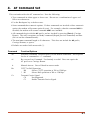
1
WTI Part No.: 13132
Rev. A
SRM-100
Secure Rack Modem
AT Command Reference Guide;
Rockwell Format Modems
5 Sterling · Irvine · California 92618-2517
(949) 586-9950 · Toll Free: 1-800-854-7226
Fax: (949) 583-9514 · http://www.wti.com
Table of Contents
1.
Introduction . . . . . . . . . . . . . . . . . . . . . . . . . . . . . . . . . . . . . . . . . . . . . 1-1
2.
Communicating with the Internal Modem . . . . . . . . . . . . . . . . . . . . . . . . . . . 2-1
3.
Modem Status . . . . . . . . . . . . . . . . . . . . . . . . . . . . . . . . . . . . . . . . . . . . 3-1
4.
AT Command Set . . . . . . . . . . . . . . . . . . . . . . . . . . . . . . . . . . . . . . . . . . 4-1
5.
S-Registers . . . . . . . . . . . . . . . . . . . . . . . . . . . . . . . . . . . . . . . . . . . . . . 5-1
6.
Modem Result Codes . . . . . . . . . . . . . . . . . . . . . . . . . . . . . . . . . . . . . . . 6-1
List of Figures
1.
The Modem Status Screen (Defaults Shown) . . . . . . . . . . . . . . . . . . . . . . . . . 3-1
i
1.
Introduction
The SRM-100 Secure Rack Modem is designed for applications that require secure, dial-up
access to console ports on rack mounted equipment. WTI's Secure Rack Modem can recognize
up to 100 passwords, track activity for each password and create a log record of successful
and/or unsuccessful access attempts.
In addition to the SRM's Menu Driven configuration functions, the internal modem will also
accept AT commands. This document describes the AT command set for Rockwell format
modems, and lists the function of each command.
If necessary, the AT command can be used to select advanced modem configuration parameters,
some of which may not be available via the SRM's menuing system. AT commands can be sent
directly to the modem, or added to the user defined initialization string via the SRM's Modem
Parameters menu.
Note: For information on general SRM-100 installation, configuration, and
operation procedures, please refer to the SRM-100 User's Guide (WTI P/N 13051).
About this Document
This document describes the AT Command Set, S-Register configuration, and Modem Response
Codes for all SRM-100 units that include the Rockwell format modem. Depending on when you
purchased your SRM, it may include either a Rockwell format modem or a Multi-Tech format
modem.
In order to determine which modem is included in your SRM unit, please refer to the SRM-100
Help Screen (/H); locate the field that lists the Modem Type, and then refer to the table below.
Listed Modem Type
Modem Format
V.2000-V34_ACF_DP1
Rockwell Format
MT2834ZPX
Multi-Tech Format
1-1
2.
Communicating with the Internal Modem
In order to invoke AT commands, you must communicate directly with the SRM's internal
modem. The Modem Command mode is only available via the Console Port or the serial
modem port; inbound callers cannot communicate directly with the modem. To send AT
commands to the SRM's internal modem proceed as follows:
1. Via Console Port: Access the SRM command Mode as described in Section 5.1.1 in the
SRM-100 User's Guide.
a) When the "SRM>" command prompt appears, type /U and press [Enter] to display
the SRM Utilities Screen.
b) When the Utilities Screen appears, type 8 and press [Enter] to activate the PassThrough mode. When the Pass-Through Mode is active, the device connected to the
Console Port can send AT commands directly to the SRM's internal modem.
c) To exit the Pass-Through Mode, type /X and press [Enter], the unit will return to the
"SRM>" command prompt.
2. Via Modem Port: The device connected to the SRM's Modem Port can also issue AT
commands. Go to the secure device and start your communications program (e.g.
ProComm). Make certain that the communications program is configured to use the same
COM port that is connected to the SRM.
2-1
3.
Modem Status
The SRM's internal modem can generate a status screen, which lists currently selected settings
for most of the AT commands, the contents of most of the S-Registers, the two stored modem
profiles, and four stored phone numbers.
To display the modem status screen, access the internal modem's command mode (as described
in Section 9.1, in the SRM-100 User's Guide), then type AT&V and press [Enter]. The internal
modem will display the status screen shown in Figure 1 below.
ACTIVE PROFILE
B1 E0 L1 M1 N1 Q1 T V1 W0 X4 Y0 &C1 &D2 &G0 &J0 &K3 &Q5 &R1 &S0 &T5 &X0 &Y0
S00:001 S01:000 S02:043 S03:013 S04:010 S05:008 S06:002 S07:050 S08:002 S09:006
S10:014 S11:095 S12:050 S18:000 S25:005 S26:001 S36:007 S37:000 S38:020 S44:020
S46:138 S48:007 S95:000
STORED PROFILE 0
B1 E1 L1 M1 N1 Q0 T V1 W0 X4 Y0 &C1 &D2 &G0 &J0 &K3 &Q5 &R1 &S0 &T5 &X0
S00:000 S02:043 S06:002 S07:050 S08:002 S09:006 S10:014 S11:095 S12:050 S18:000
S36:007 S37:000 S40:104 S41:195 S46:138 S95:000
STORED PROFILE 1
B1 E1 L1 M1 N1 Q0 T V1 W0 X4 Y0 &C1 &D2 &G0 &J0 &K3 &Q5 &R1 &S0 &T5 &X0
S00:000 S02:043 S06:002 S07:050 S08:002 S09:006 S10:014 S11:095 S12:050 S18:000
S36:007 S37:000 S40:104 S41:195 S46:138 S95:000
TELEPHONE NUMBERS
0=
2=
1=
3=
Figure 1: The Modem Status Screen (Defaults Shown)
3-1
4.
AT Command Set
This section describes the AT command set. Note the following:
· Type commands in either upper or lower case. Do not use a combination of upper and
lower case characters.
· Use the Backspace key to delete errors.
· Some commands have numeric options. If these commands are invoked without a numeric
option, the modem will assume option 0 (zero). For example, when the command ATE is
invoked, the modem will assume command ATE0 was intended.
· All commands begin with the AT prefix, and are invoked by pressing [Enter] (Carriage
Return). The only exceptions are the A/ command (Repeat previous command) and +++
(Exit to on-line command mode).
· The maximum command length is 40 characters. This does not include the AT prefix,
Carriage Returns, or spaces.
· Defaults are marked with an asterisk (*).
Command
Function/Options
AT
Attention Command. Required prefix for all modem commands. Not required
for the A/ command or +++ command.
A/
Re-execute Last Command. Used mainly to redial. Does not require the
AT prefix or a Carriage Return.
A
Manual Answer. Goes off hook in answer mode.
Bn
CCITT or Bell Operation
B0
Selects CCITT operation at 300 or 1200 bps.
* B1
Selects Bell operation at 300 or 1200 bps.
Cn
Transmit Carrier Signal
C0
Not Supported.
C1
Enable Transmit Carrier Signal.
4-1
SRM-100 - AT Command Reference Guide; Rockwell Format
Command
AT Command Set
Function/Options
Dn
Dial Command. Dials the specified phone number. Can also include the
following command options:
*
Dials the “star” digit (tone dialing only).
#
Dials the “pound” digit (tone dialing only).
L
Re-dials last number dialed
P
Pulse (Rotary) Dial Mode. 10 pulses per second.
T
Tone Dial Mode (DTMF).
W
Wait for dial tone (1 to 255 seconds, Default = 50 sec.)
,
(Comma) Pause. Modem will pause for time period specified by
register S8 before dialing (0 to 255 seconds, Default = 2 sec.)
@
Wait for quiet answer.
!
(Exclamation Point) Flashes the switch hook.
;
(Semicolon) Return to Command Mode after dialing.
&
Wait for credit card dial tone before continuing with dial string.
If the bong is not detected within the time specified by register S7,
the modem will abort the dial sequence, go on-hook, and generate
an error message.
^
Toggles calling tone for current dial attempt only.
S=n
Dial stored number (where n = 0 to 3).
()
(Parentheses) Ignored; may be used to format the dial string.
(Dash) Ignored; may be used to format the dial string.
<Space> Ignored; may be used to format the dial string.
En
Set Local Echo.
* E0
Disable echoing of commands to screen.
E1
Enable echoing of commands to screen.
Hn
Disconnect (Hang-Up)
H0
Hangs Up (goes on-hook).
H1
Goes off-hook.
In
Modem Identification
I0
Display product identification code.
I1
Display checksum.
I2
Display ROM checksum as OK or ERROR.
I3
Display modem firmware revision level.
I6
Report modem data pump and internal code revision.
Ln
Modem Speaker Volume
L0
OFF or low volume.
* L1
Low volume.
L2
Medium volume.
L3
High volume.
4-2
SRM-100 - AT Command Reference Guide; Rockwell Format
Command
AT Command Set
Function/Options
Mn
Modem Speaker Control
M0
Disable Modem Speaker.
* M1
Speaker ON until carrier is detected.
M2
Speaker always ON.
M3
Speaker ON after dial, until connection is established.
Nn
Enable/Disable Automode
N0
Disable automode detection (equivalent to setting the
+MS<automode> subparameter to 0). A subsequent handshake
will be conducted as specified by register S37, or if S37=0,
according to the most recently sensed DTE speed.
* N1
Enable automode detection (equivalent to setting +MS<automode>
subparameters to 1). A subsequent handshake will be conducted as
specified by register S37, or if S37=0, starting at 28,800 bps V.34.
Notes:
• The Nn and S37=x commands override the +MS command settings. When the N0
or N1 command is issued, the +MS subparameters are updated accordingly. For
example, “N1S37=10” updates the +MS command subparameters to reflect
“+MS=10,1,300,12000”; while “N0S37=10” updates the +MS command
subparameters to “+MS=10,0,300,12000”.
• It is recommended to use the +MS commands instead of the Nn and S37=x
commands.
• Nn and S37=x commands are supported for compatibility with existing
communication software.
On
P
Qn
Sr=n
Sr?
T
Return to On-Line Mode.
O0
Switches modem from command mode to on-line mode after
dropping to command mode using the escape sequence (+++).
O1
Switches from command mode to on-line mode and initiates an
equalizer retrain sequence before returning to on-line mode.
Set Pulse Dial as Default. Forces pulse dialing until the next T dial modifier or
T command is received.
Enable/Disable Result Codes
Q0
Enable result codes.
* Q1
Disable result codes (quiet mode).
Set Register r to Value n. See list of S-Registers in Section 10.
Display Current Value of Register r.
Sets Tone Dial as Default. Forces tone dialing until the next P dial modifier or
P command is received.
4-3
SRM-100 - AT Command Reference Guide; Rockwell Format
Command
AT Command Set
Function/Options
Vn
Result Code Format.
* V0
Numeric format.
V1
Verbal format.
Wn
Error Correction Message Control.
* W0
Upon connection, modem reports DTE speed only.
W1
Upon connection, modem reports line speed, error correction
protocol, and DTE speed.
W2
Upon connection, modem reports DCE speed.
Xn
Extended Result Codes.
X0
Disables monitoring of busy tones unless forced by country
requirements; sends only OK, CONNECT, RING, NO CARRIER,
ERROR, and NO ANSWER result codes.
X1
Disables monitoring of busy tones unless forced by country
requirements; sends only OK, CONNECT, RING, NO CARRIER,
ERROR, NO ANSWER, and CONNECT XXXX result codes.
X2
Disables monitoring of busy tones unless forced by country
requirements; sends only OK, CONNECT, RING, NO CARRIER,
ERROR, DIAL TONE, NO ANSWER, and CONNECT XXXX
result codes.
X3
Enables monitoring of busy tones; sends only OK, CONNECT,
RING, NO CARRIER, ERROR, NO DIALTONE, NO ANSWER,
and CONNECT XXXX result codes.
* X4
Enables monitoring of busy tones and sends all messages.
Yn
Enable/Disable Long Space Disconnect.
* Y0
Disable long space disconnect.
Y1
Enable long space connect.
Zn
Soft Reset and Restore Profile.
* Z0
Restores stored profile 0.
Z1
Restores stored profile 1.
+++
Escape Sequence. Switches from on-line mode to command mode while
preserving the connection with the on-line modem.
&Cn
Controls Data Carrier Detect (DCD) Signal.
&C0
Forces DCD signal to be ON at all times.
* &C1
Normal DCD operation (required by most software).
4-4
SRM-100 - AT Command Reference Guide; Rockwell Format
Command
AT Command Set
Function/Options
&Dn
Control Data Terminal Ready (DTR) Signal. Interprets the ON to
OFF transition of the DTR signal from the DTE as specified by
the &Qn setting.
&D0
&Q0,5,6: DTR ignored.
&Q1,4: Modem hangs up; auto answer not effected.
&Q2,3: Modem hangs up; auto answer inhibited
&D1
&Q0,1,4-6: Asynchronous escape sequence.
&Q2,3: Modem hangs up; auto answer inhibited.
* &D2
&Q0-6: Modem hangs up; auto answer inhibited.
&D3
&Q0,1,4-6: Modem performs soft reset as if the ATZ command
were received.
&Q2,3: Modem hangs up; auto answer inhibited.
&Fn
Load Factory Defaults. Instructs the modem to load the factory set parameters
(non-programmable).
&F0
Load factory defaults 0.
&F1
Load factory defaults 1.
&Gn
Select Guard
* &G0
&G1
&G2
&Jn
Telephone Jack Control.
* &J0
No Function. Included for compatibility.
&J1
No Function. Included for compatibility.
&Kn
DTE/Modem Flow Control.
&K0
Disable flow control.
* &K3
Enable RTS/CTS.
&K4
Enable XON/XOFF.
&K5
Enable transparent XON/XOFF.
&K6
Enable both RTS/CTS and XON/XOFF
&Pn
Select Pulse
* &P0
&P1
&P2
&P3
&Qn
Asynchronous Mode
&Q0
Direct Asynchronous Mode. All Error Correction and
Compression protocols are disabled. This requires that the
software’s baud rate matches modem baud rate.
* &Q5
Modem negotiates an error correction link.
&Q6
Selects asynchronous operation in normal mode.
(Speed buffering allows software baud rate to be fixed).
Tone.
Disable guard tone.
Disable guard tone.
Select 1800 Hz guard tone.
Dial Make/Break Ratio.
USA/Canada ratio (39/61 at 10 pps).
UK/Hong Kong ratio (33/67 at 10 pps).
Same as &P0, except at 20 pps.
Same as &P1, except at 20 pps.
4-5
SRM-100 - AT Command Reference Guide; Rockwell Format
Command
AT Command Set
Function/Options
&Rn
RTS/CTS Option.
&R0
In sync mode, CTS tracks the state of the RTS signal; the
RTS-to-CTS delay is defined by register S26. In async mode, the
CTS signal acts according to V.25bis handshake.
* &R1
In sync mode, CTS is always ON (RTS transition is ignored). In
async mode, CTS will only drop if required by flow control.
&Sn
Data Set Ready (DSR) Signal.
* &S0
DSR override; always ON.
&S1
DSR signal ON after answer tone is detected, and OFF after the
carrier is lost.
&Tn
Test and Diagnostics. Modem will perform selected test and diagnostic
function. Note that Tests can only be run in asynchronous mode, with error
correction disabled.
&T0
Terminate test in progress.
&T1
Execute local Analog Loopback Test.
&T3
Execute Local Digital Loopback Test.
&T4
Enable modem to accept remote request for Digital Loopback Test.
* &T5
Deny remote request for Digital Loopback Test.
&T6
Execute remote Digital Loopback Test.
&T7
Execute remote Digital Loopback Test with self test.
&T8
Execute remote Analog Loopback Test with self test.
&V
View Current Configuration. Displays the active profile, stored profiles, and
stored phone numbers.
&Wn
Store User Profile. Saves the current configuration in NVRAM.
&W0
Save as User Profile 0.
&W1
Save as User Profile 1.
&Yn
Select Default User Profile
* &Y0
Select User Profile 0.
&Y1
Select User Profile 1.
&Z=n
Store Phone
&Z=0 Store
&Z=1 Store
&Z=2 Store
&Z=3 Store
Number to NVRAM (36 digit dial string).
phone number at position 0.
phone number at position 1.
phone number at position 2.
phone number at position 3.
4-6
5.
S-Registers
The S-Registers are used to store modem configuration parameters, display modem status, and
initiate modem test and diagnostic functions. In order to invoke commands to change or
display the contents of the S-Registers, you must first access the modem command mode as
described in Section 9.1 in the SRM-100 User's Guide. Note the following:
· View Status Screen: To display the modem status screen (Figure 9.1), which lists the
current values assigned to most S-Registers, type AT&V and press [Enter].
· View S-Register Value: To display the value currently assigned to a specific S-Register,
type ATSr? and press [Enter] (Where r is the desired S-Register).
· Change S-Register Value: To change the value assigned to an S-Register, type ATSr=n
and press [Enter] (Where r is the desired S-Register, and n is the desired value).
· Bit Mapped Registers: Some registers control more than one function. If you wish to
enable several of these functions, add up the decimal values of the desired functions, and
enter the total as the value of the S-Register.
Register
Range
Default
Function
S00
0 - 255
1
Auto Answer. Sets the number of rings on which to answer in Auto Answer
Mode. When set to 0, Auto Answer is disabled.
S01
0 - 255
0
Ring Count. Counts and stores the number of rings from an incoming call.
This value is cleared if a ring is not detected over an 8 second period. If the
value of register S1 equals the value of register S0, the modem will answer
the phone.
S02
0 - 127
43
Escape Character Code. Stores the ASCII decimal code for the escape code
character. The default character is + (043).
S03
0 - 127
13
Carriage Return Character. Stores the ASCII code for the Carriage Return
character. The default value is 013 (normal carriage return).
S04
0 - 127
10
Line Feed Character. Stores the ASCII decimal code for the Line Feed
character. The default value is 010 (normal line feed).
S05
0 - 032
8
Backspace Character. Stores the ASCII decimal code for the Backspace
character. The default value is 008 (normal backspace character).
S06
2 - 255
2
Wait for Dial Tone. Sets the number of seconds the modem will wait between
going off-hook and beginning dialing.
S07
0 - 255
50
Wait for Carrier. Sets the number of seconds the modem will wait for a
carrier signal from a remote modem. If a carrier is not received, the modem
will hang-up and send the NO CARRIER message. Often used to select a
longer duration when the modem is originating an international connection.
S08
0 - 255
2
Pause Time for Carrier. Sets the duration (in seconds) for the Dial command
pause option (,).
5-1
SRM-100 - AT Command Reference Guide; Rockwell Format
S-Registers
Register
Range
Default
Function
S09
1 - 225
6
Carrier Detect Response Time. Determines the length of time (in tenths of a
second) required for the modem to recognize the receive character from the
remote modem, and turn on the DCD.
S10
1 - 255
14
Lost Carrier to Hang-Up Delay. Sets the length of time (in tenths of a
second) the modem will wait after loss of carrier before hanging up. If this
value is set lower than the value contained in S09, a loss of carrier will
always result in disconnection.
S11
50 - 255
95
Duration / Spacing DTMF. Sets the duration and spacing (in milliseconds)
between DTMF (touch tone) dialing characters.
S12
0 - 255
50
Escape Prompt Delay (EDP). Defines the maximum period (in fiftieths of a
second), allowed between receipt of the last character in the escape code
(+++), from the DTE and sending of the OK result code to DTE. If any
characters are detected during this time, the OK will not be sent.
S13
---
---
Not Used.
S14
---
---
Bit Mapped Options.
Bit
0
1
Option
Used Internally
Command Echo
2
Result Codes
3
Result Code Type
4
5
Used Internally
Dial Method
6
7
Used Internally
Originate/Answer
S15
---
---
Not Used
S16
---
---
Modem Test Options.
Bit
0
Option
Local Analog Loopback
1
2
Not Used
Local Digital Loopback
3
Status Bit
4
Initiate Remote
Digital Loopback
Remote Digital Loopback
With Error Count
Local Analog Loopback
With Self Test
Not Used
5
6
7
Val
Descrip
Cmd
0
1
0
1
0
1
Disabled
Enabled
Enabled
Disabled
Numeric
Verbal
E0
E1
Q0
Q1
V0
V1
0
1
Tone
Pulse
T
P
0
1
Answer
Originate
A
D
Val
0
1
Descrip
Disabled
Enabled
Cmd
0
1
0
1
0
1
0
1
0
1
Disabled
Enabled
Loopback Off
In Progress
Disabled
Enabled
Disabled
Enabled
Disabled
Enabled
&T1
&T3
&T6
&T7
&T8
5-2
SRM-100 - AT Command Reference Guide; Rockwell Format
S-Registers
Register
Range
Default
Function
S17
---
---
Not Used.
S18
0 - 255
0
Test Timer. Test timer for &Tn loopback testing. Sets the length of time (in
seconds) the modem will wait before automatically timing out and
terminating the test. When set to 0, the timer is disabled, and the test must
be terminated by issuing an &T0 or H command.
S19
---
---
Not Used.
S20
---
---
Not Used.
S21
---
---
Bit Mapped Options.
Bit
0
Option
Telephone Jack
1
2
Not Used
RTS/CTS
3,4
DTR
Val
0
1
Descrip
RJ11
RJ12
Cmd
&J0
&J1
&R0
&R1
&D0
&D1
0
1
CTS/RTS
CTS always true
Ignore DTR
Modem to Cmd. State on
On-to-Off DTR transition.
Modem hangs-up on
On-to-Off DTR transition.
Init. state on On-to-Off
DTR transition.
Always On
Follows Carrier
0
1
Disabled
Enabled
0
1
0
1
2
3
S22
---
---
5
DCD
6
7
Not Used
Long Space Disconnect
&D2
&D3
&C0
&C1
Y0
Y1
Bit Mapped Options
Bit
0,1
Option
Speaker Volume
2,3
Speaker Control
4-6
Result Codes
7
Make/Break Ratio
Val
0
1
2
3
0
1
2
3
0
4
5
6
7
0
1
Descrip
Low
Low
Medium
High
Speaker Off
On until carrier detected
Always On
On until carrier detected,
but Off while dialing
See X0
See X1
See X2
See X3
See X4
39:61 (USA)
33:67 (UK)
Cmd
L0
L1
L2
L3
M0
M1
M2
M3
X0
X1
X2
X3
X4
&P0
&P1
5-3
SRM-100 - AT Command Reference Guide; Rockwell Format
Register
Range
Default
S23
---
---
S-Registers
Function
Bit Mapped Options.
Bit
0
Option
Obey request from remote modem
for remote digital loopback test
1-3
Assumed DTE Rate
4,5
Parity Option
6,7
Guard Tones
Val
0
1
0
1
2
3
4
5
6
0
1
2
3
0
1
2
Descrip
Disabled
Cmd
&T5
Enabled
300 bps
600 bps
1200 bps
2400 bps
4800 bps
9600 bps
19.2K bps
Even
Space
Odd
Mark
Disabled
550 Hz
1800 Hz
&T4
&G0
&G1
&G2
S24
---
---
Not Used.
S25
0 - 255
5
Async DTR Delay. Sets the duration (in hundredths of a second) that DTR
must be dropped in order to be interpreted as a DTR loss. Allows the modem
to differentiate between a random glitch and a true DTR loss.
In most cases, the default value can be used. The S25 register is useful for
setting compatibility with older systems running under older operating
software.
S26
0 - 255
1
Sync RTS/CTS Delay. The modem will ignore a change in RTS/CTS status
for the time interval (in hundredths of a second) defined in this register, when
in the synchronous mode.
S27
---
---
Bit Mapped Options.
Bit
0,1,3
S28
---
---
Option
Operation Mode
2
Line Type
4,5
Transmit Clock
6
Service Type
7
Not Used.
Bits
0 1
0 0
0 0
0 1
0 1
1 0
1 0
1 1
0
1
0
1
2
0
1
3
0
1
0
1
0
1
0
Descrip
Cmd
See &Q0
See &Q1
See &Q2
See &Q3
See &Q4
See &Q5
See &Q6
Dial Up
Leased Line
Internal
External
Slave
CCITT
Bell 212A
&M0
&M1
&M2
&M3
&Q4
&Q5
&Q6
&L0
&L1
&X0
&X1
&X2
B0
B1
or
or
or
or
&Q0
&Q1
&Q2
&Q3
Not Used.
5-4
SRM-100 - AT Command Reference Guide; Rockwell Format
S-Registers
Register
Range
Default
Function
S29
0 - 255
---
Flash Dial Modifier Time. Sets the length of time (in hundredths of a
second) that the modem will go off-hook when it encounters the flash (!) dial
modifier in the dial string.
S30
0 - 255
---
Disconnect Inactivity Timer. Sets the length of time (in 10 second intervals)
that the modem will stay on-line before disconnecting when no data is sent or
received. In error-correction mode, any data transmitted or received will
reset the timer. In other modes, any data transmitted will reset the timer.
The timer is inoperative in synchronous mode.
S31
---
---
Bit Mapped Options.
Bit
0
1
Option
Not Used
Speed Detection
2,3
Progress Messages
4-7
Not Used.
Val
0
1
0
1
2
Description
Disabled
Enabled
DTE Speed
Full Reporting
DCE Speed
Cmd
N0
N1
W0
W1
W2
S32
0 - 255
17
XON Character. Stores the ASCII decimal code for the XON character.
S33
0 - 255
19
XOFF Character. Stores the ASCII decimal code for the XOFF character.
S36
0-7
7
V.42 Negotiation Failure Treatment. This register is read when the S48
register equals 128 or if an attempted V.42 connection fails. These fallback
options are initiated immediately upon connection if S48 = 128.
S36=0
S36=1
S36=2
S36=3
S36=4
S36=5
S36=6
S36=7
S37
0 - 21
0
Modem Disconnects.
Modem stays on-line and a direct mode connection is established.
Reserved.
Modem stays on-line and a normal mode connection is
established.
An MNP connection is attempted. If this connection fails, the
modem then disconnects.
An MNP connection is attempted. If this connection fails,
a direct mode connection is established.
Reserved.
An MNP connection is attempted. If this connection fails, a
normal mode connection is established.
Desired Connection Rate.
S37=0
S37=1-3
S37=4
S37=5
S37=6
S37=7
S37=8
S37=9
S37=10
S37=11
S37=12
Attempt auto mode
Attempt to connect
Reserved.
Attempt to connect
Attempt to connect
Attempt to connect
Attempt to connect
Attempt to connect
Attempt to connect
Attempt to connect
Attempt to connect
connection.
at 300 bps.
at
at
at
at
at
at
at
at
1200 bps.
2400 bps.
V.23
4800 bps.
9600 bps.
12K bps.
14.4K bps.
7200 bps.
5-5
SRM-100 - AT Command Reference Guide; Rockwell Format
S-Registers
Register
Range
Default
S38
0 - 255
20
Delay Before Forced Hang Up. This register specifies the delay (in seconds)
between the modem’s receipt of the H command to disconnect (or On-to-Off
transition of DTR if the modem is set to follow the signal), and the
disconnect operation. Applicable to error correction connection only. This
register can be used to ensure that data in the modem buffer is sent before the
modem disconnects.
S39
---
---
Bit Mapped Register.
S40
---
---
Bit Mapped Register.
S41
---
---
Bit Mapped Register.
S46
136 or
138
138
Protocol Selection. This register controls V.42bis compression.
0, 7 or
128
7
S48
Function
S46=136
S46=138
Disable V.42bis compression.
Enable V.42bis compression.
V.42 Negotiation Action. The V.42 negotiation process determines the
capabilities of the remote modem. Note that this process is bypassed when
the capabilities of the remote modem are known and negotiation is
unnecessary.
S48=0
S48=7
S48=128
Disables negotiation. Bypasses the detection and negotiation
phases, and proceeds with V.42 (LAPM).
Enables negotiation.
Disables negotiation. Bypasses the detection and negotiation
phases, and proceeds with the fallback action specified by
register S36. Can be used to force MNP.
S82
---
---
S82 is included for compatibility purposes only. Changing this register will
have no effect.
S86
0, 4, 5, 8,
12, 13, or
14
---
Connection Failure Cause Code. When the modem issues a NO CARRIER
result code, a value is written to this S register to help determine the reason
for the failed connection. S86 records the first event that contributes to a NO
CARRIER message.
S86=0
S86=4
S86=5
S86=9
S86=12
S86=13
S86=14
Normal Disconnect, no error occurred.
Loss of carrier.
V.42 negotiation failed to detect an error correcting modem at
the other end.
The modems could not find a common protocol.
Normal disconnect initiated by the remote modem.
Remote modem does not respond after 10 re-transmissions of
the same message.
Protocol violation.
5-6
SRM-100 - AT Command Reference Guide; Rockwell Format
Register
Range
Default
S95
---
000
S-Registers
Function
Extended Result Codes. The bits in this register can be set to override some
of the Wn command options. A bit set to 1 in this register will enable the
corresponding result code regardless of the
Wn setting.
Bit
0=
Dec Value
1
1=
2
2=
3=
5=
4
8
32
Function
CONNECT CODE indicates DCE speed instead of
DTE speed.
Append /ARQ (Automatic Repeat Request) to
verbose CONNECT XXXX result code if protocol is
other than none.
Enable CARRIER XXX result code.
Enable PROTOCOL XXXX result code.
Enable COMPRESSION result code.
Note: To enable more than one function, add up the decimal values of the
desired functions. For example, to enable CARRIER, PROTOCOL, and
COMPRESSION, you would add 32 + 8 + 4 for a total of 44. Therefore, the
command to enable these functions would be ATS95=44.
5-7
6.
Modem Result Codes
When AT commands are invoked, the modem will respond with either Terse (numeric) or
Verbose (text) result codes. The result code format is set using the Modem Parameters Menu
(/M), or the ATVn command. Result Codes can also be completely suppressed by enabling the
Quiet Mode via the Modem Parameters Menu or the ATQn command.
Notes:
• The CARRIER Result Code must be enabled using S95 bit 2 or the ATW1
command.
• The COMPRESSION Result Code must be enabled using S95 bit 5.
• The PROTOCOL Result Code must be enabled using S95 bit 3 or the ATW1
command.
Verbose
Response
Terse
Response
Description
OK
0
Modem Successfully executed a command.
CONNECT
1
Connection made at 300 bps.
RING
2
Modem detected an incoming call.
NO CARRIER
3
Modem lost or could not detect a remote carrier signal within
the Register S7 time.
ERROR
4
Modem found an error in the command line.
CONNECT 1200
5
Connection made at 1200 bps.
NO DIALTONE
6
Modem did not detect a dial tone within 5 seconds after
going off-hook.
BUSY
7
Modem detected a busy signal.
NO ANSWER
8
Five seconds of silence was not detected when using the @
command in the ATD command.
CONNECT 0600
9
Connection made at 600 bps.
CONNECT 2400
10
Connection made at 2400 bps.
CONNECT 4800
11
Connection made at 4800 bps.
CONNECT 9600
12
Connection made at 9600 bps.
CONNECT 7200
13
Connection made at 7200 bps.
CONNECT 12000
14
Connection made at 12000 bps.
CONNECT 14400
15
Connection made at 14400 bps.
CONNECT 16800
59
Connection made at 16800 bps.
6-1
SRM-100 - AT Command Reference Guide; Rockwell Format
Verbose
Response
Terse
Response
Modem Result Codes
Description
CONNECT 19200
16
Connection made at 19200 bps. (If modem is set to respond
with connect message that indicates carrier rate, otherwise
indicates software rate).
CONNECT 21600
61
Connection made at 21600 bps.
CONNECT 24000
62
Connection made at 24000 bps.
CONNECT 26400
63
Connection made at 26400 bps.
CONNECT 28800
64
Connection made at 28800 bps.
CONNECT 38400
17
Connection made at 38400 bps. (Indicates software rate).
CONNECT 57600
18
Connection made at 57600 bps.
(Indicates software rate).
CONNECT 115200
19
Connection made at 115200 bps.
(Indicates software rate).
FAX
33
Fax Detected. (Fax/Data answer mode).
DATA
35
Modem detected. (Fax/Data answer mode).
CARRIER 300
40
Carrier rate of 300 bps.
CARRIER 1200
46
Carrier rate of 1200 bps.
CARRIER 2400
47
Carrier rate of 2400 bps.
CARRIER 4800
48
Carrier rate of 4800 bps.
CARRIER 7200
49
Carrier rate of 7200 bps.
CARRIER 9600
50
Carrier rate of 9600 bps.
CARRIER 12000
51
Carrier rate of 12000 bps.
CARRIER 14400
52
Carrier rate of 14400 bps.
CARRIER 16800
53
Carrier rate of 16800 bps.
CARRIER 19200
54
Carrier rate of 19200 bps.
CARRIER 21600
55
Carrier rate of 21600 bps.
CARRIER 24000
56
Carrier rate of 24000 bps.
CARRIER 26400
57
Carrier rate of 26400 bps.
CARRIER 28800
58
Carrier rate of 28800 bps.
COMPRESSION:
CLASS 5
66
The modem has connected in MNP class 5 and
COMPRESSION message reporting has been enabled.
COMPRESSION:
V.42BIS
67
The modem has connected in V.42bis and COMPRESSION
message reporting has been enabled.
6-2
SRM-100 - AT Command Reference Guide; Rockwell Format
Verbose
Response
Terse
Response
Modem Result Codes
Description
COMPRESSION:
NONE
69
The modem has connected without data compression and
COMPRESSION message reporting has been enabled.
PROTOCOL:
NONE
76
The modem has connected without any form of error
correction. (NO MNP4 or V.42).
PROTOCOL:
LAPM
77
The modem has connected in the V.42 LAPM mode of error
correction.
PROTOCOL:
ALT
80
The modem has connected in the MNP4 mode of error
correction.
6-3
SRM-100 - AT Command Reference Guide; Rockwell Format
Modem Result Codes
Customer Service
Customer Service hours are from 8:00 AM to 5:00 PM, PST, Monday through Friday. When
calling, please be prepared to give the name and make of the unit, its serial number and a
description of its symptoms. If the unit should need to be returned for factory repair it must be
accompanied by a Return Authorization number from Customer Service.
WTI Customer Service
5 Sterling
Irvine, California 92618
Local Phone: (949) 586-9950
Toll Free Service Line: 1-888-280-7227
Service Fax: (949) 457-8138
Email: [email protected]
Trademark and Copyright Information
WTI and Western Telematic are trademarks of Western Telematic, Inc. All other product names
mentioned in this publication are trademarks or registered trademarks of their respective
companies.
Information and descriptions contained herein are the property of Western Telematic, Inc.
Such information and descriptions may not be copied disseminated or distributed without the
express written consent of Western Telematic, Inc.
© Copyright Western Telematic, Inc. 2000
April 2001
Part Number: 13132 Revision: A
6-4