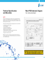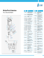
1
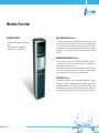
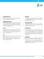
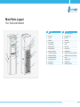
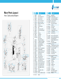
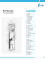
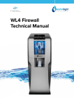
WL 1000 GF
Technical Manual
Waterlogic 1000 GF Technical Manual - Issue A, July 2011
Index
Machine Overview
Filter Parts Layout - Hot, Cold and Ambient
Main Parts Layout
Pre Delivery Inspection (PDI)
Installation
Operating Instructions
Maintenance and Service
Reverse Osmosis Specification
Sanitization
Fault Finding
Technical Specifications and Warranties
Electrical Schematic Diagram PCB
Wetted Parts
End of Life
Biocote frequently asked questions
4
8
10
16
18
21
23
25
26
26
28
29
30
32
33
Waterlogic 1000 GF Technical Manual - Issue A, July 2011
2
3
Machine Overview
WATERLOGIC 1000 GF
COLD TANK CAPACITY (4 Litres)
The WL1000 GF is available in the following
option:
• Freestanding Cold, Hot and Ambient
with Reverse Osmosis (RO) Filtration.
The cold tank is manufactured from 304 Stainless Steel which is noncorrosive and
inert. The temperature of the Cold Tank is controlled by a mechanical thermostat
located on the rear panel of the machine and can be set between 3°C and 12°C. We
recommend the cold water is set at 5°C, which is the factory setting and is the ideal
temperature for a cold drink. The set point for the thermostat is marked with a
black dot.
HEADER STORAGE TANK (11.5 Litres)
The plastic header tank has a capacity of 11.5 litres of purified water. This tank can
be drained and removed from the machine for cleaning. It is made with Biocote
additive to inhibit any bacteria growth.
The level of the header tank is controlled by an electrical float switch which controls
the inlet solenoid valve and Reverse Osmosis System. There is a mechanical float
valve to control any tank overfill and gives an overfill failsafe feature.
HOT TANK (1.5 litres)
The hot tank has a capacity of 1.5 litres and is made of stainless steel. The water
temperature is controlled by a Mechanical Thermostat and is factory set at 85°C. A
thermal high temperature cut out is fitted to the Hot Tank and the tank has a 500
Watt immersed heating element. The high temperature cut out has a manual reset
button, please isolate the power before resetting. The hot water tank is a sealed unit.
Waterlogic 1000 GF Technical Manual - Issue A, July 2011
Waterlogic 1000 GF Technical Manual - Issue A, July 2011
4
5
REVERSE OSMOSIS FILTERS
COMPRESSOR
The filtration system is a 4-stage system, consisting of sediment, pre-carbon,
Reverse Osmosis membrane, and post carbon filters.
The compressor operates at 220-240V at 50Hz. It uses 75 grams of R134a nonOzone depleting refrigerant gas. Do not place the machine too near a heat source
as it will affect the compressor efficiency.
REVERSE OSMOSIS WATER PUMP
The 1000 GF is fitted with a water pump and pressure switch to ensure a constant
pressure across the RO membrane. If the input water pressure falls below 1.5 bar
then the water pump will not run. The water pump outlet pressure is 60 PSI allowing
the membrane to meet 50GPD water production
WATER PIPE AND FITTINGS
UV LAMP
INLET WATER VALVE
The UV light is an 8 Watt germicidal lamp at a wavelength of 253.7 NM, which is
very efficient at destroying bacteria in water. The UV lamp is situated in the cold
tank surrounded by a quartz sleeve. The lamp must be replaced at 6 months
intervals, and the quartz sleeve cleaned.
PCB
The PCB (Printed Circuit Board) is the indicator and pump control unit for the WL
GF1000, the display (at the top of the GF1000) informs the user of the status of the
unit. There are three different LED lights on the display PCB showing power on,
heating, or cooling status of the machine.
The inlet water pipe adaptor and the internal water circuit pipe sizes are 1/4”, 5/16”
and.3/8”. The entire internal water circuit and all the components which come in
contact with water are food grade approved.
The inlet of water to the machine is controlled by means of a 230V AC electrical
solenoid valve. The valve is energized by the header tank electrical float switch.
There is also a leak detection float switch located in the base leak catchment tray
of the machine that will cut electrical power to the inlet solenoid valve should there
be a internal water leak. The inlet valve comes with a pipe reduction fitting to allow
a ¼” pipe connection.
PLASTIC PANELS
The moulded panels are made from recyclable ABS plastic. All the ABS plastic
panels are UV resistant and meet the standards of CE and UL. Please note that the
1000 GF should not be exposed to direct sunlight. Placing the 1000GF in direct
sunlight from a window, close to a radiator, or in a room of high ambient temperature,
will affect the efficiency of the refrigeration circuit.
Waterlogic 1000 GF Technical Manual - Issue A, July 2011
6
7
Filter Parts Layout
Hot, Cold and Ambient
IN (Water)
LOW
PRESSURE
VALVE
INLET SOLENOID VALVE
POST CARBON
MEMBRANE
PRE CARBON
SEDIMENT
PUMP
RESERVOIR
AMBIENT WATER OUT
HOT WATER OUT
WASTE WATER
CONTROLLER
COLD WATER OUT
HOT
TANK
COLD
TANK
COMPRESSOR
FILTER
DRYER
Waterlogic 1000 GF Technical Manual - Issue A, July 2011
8
9
Main Parts Layout
Hot, Cold and Ambient
Item
3
4
7 65
12 11 10 9
1
2
18
8
13
19
22
14
15
29
20
21
26
23/24
25
16
27
17
28
1
2
3
4
5
6
7
8
9
10
11
12
13
14
15
Description
Item Description
Handle
Side Panel
Top cover
LED label
Power indicator
Chilling indicator
Heating indicator
Front Hatch panel
Ambient push button
Cold water push button
Hot water push button
Hot safety push button
Drip tray insert panel
Drip tray grill
Drip tray body
16
17
18
19
20
21
22
23
24
25
Front down insert panel
Front down panel
Back panel
Thermostat
Power Switch
Socket
Fuse holder
Solenoid valve
JG fitting adaptor
GF insert solenoid valve cover BKT
26
GF Back panel access to electrical
service
27
28
29
Cold Water Drain
Hot Water Drain
Heater/Comp Switch
Waterlogic 1000 GF Technical Manual - Issue A, July 2011
10
11
Main Parts Layout
Hot, Cold and Ambient
71
72
73
74
75
76
77
81
80
79
78
2
3
4
5
7
6
8
1
62
63
67
68 64
69
9
70 66 65
60
59
58
57
10
12
56
55
54
13
61
18 17 16 15 14 19/20
27 26
/21/22
25
49
50
51
52
53
11
28 23 24
49
44
46 45
34
43
42 3837
36
35
33
29
32
47 48
31
41 40
39
30
Item Part
Number
1 Pl-1254
2 Pl-1290
3 Pu-4108
4 Pl-1259
5 Pu-4099
6 Pu-4100
7 Pu-4097
8 Pl-1258
9 St-8212
10 Ct-2031
11 Pl-1123
12 St-8229
13 St-8016
14 Lp-7180
15 Pl-1257
16 En-6112
17 En-6114A
18
19 Pl-1264
20 Pl-1263
21 Pl-1262
22 Pl-1265
23 Pl-1266
24 Pl-1268
25 Cst-8326
26 Pl-1269
27 Cst-8327
28 Pl-1267
29 Pl-1270
30 Pl-1211-A
31 Pl-1255
32 Pl-1260A
33 Pl-1260C
34 Pl-1256
35 Pl-1149A
36 Ro-005A
37 Ro-002A
38 Ro-001A
39 Ro-008
40 Pu-4024
41 Ro-011B
42 ST-8206A
43 RO-0023
44 RO-012
Description
Top Cover
Carbon Air Filter Cap
Carbon Air Filter
Reservoir Cover
Reservoir Seal-Silicon
Water Level Control
Mechanical inlet valve
Reservoir
Side Panel-Right
Drain
Plastic Handle Silver
Lower Panel Fixing BKT
Foot
LED Label
Front Hatch
Main PCB
Sub PCB
Sub PCB Cover
Ambient Push Button
Cold Water Push Button
Hot Water Push Button
Hot Safety Button
Hot Safety Push Pin
Faucet Pin
Spring - for push Button
Push Button BKT
Spring for Hot water lock
Hot Water Safety Lock
Drip Tray Grill
Drip Tray Body
Front Upper Panel
Hot water Faucet
Cold & Ambient faucet
Front Down Panel
Front Down Panel Insert
Post-Carbon Micro filter
Pre-Carbon Micro filter
Sediment Micro filter
Elbow Fitting 1/4' to1/4'
Clip 3'
Flow Restrictor Micro
RO BKT
Inline RO 50GPD Micro filter
Adapter
Item Part
Number
45 RO-017
46 CT-2035D
47 ST-8254
48 RO-013A
49 CO-9001B
50 PU-4100B
Description
Adapter BKT
RO Water Pump
Low Pressure Valve BKT
Low Pressure Valve Micro
Compressor 230V
GF Level Sensor
GF Level Sensor BKT
51 ST-8232
for Leak
52 PL-1292
GF Leak Tray
53 ST-8035
Down Base
54 ST-8233
Cover of Inlet SV
JG Adaptor 1/4" for inlet
55 PU-4104
solenoid valve
56 ST-8212
Side Panel-Left
57
/
/
58 PU-4095 Inlet Solenoid Valve 230V
59 ST-8214
Inlet Solenoid Valve Bracket
60 PL-1123
Plastic Handle Silver
61
/
Bulkhead Fitting 1/4' to 1/4'
62 ST-8210
Back Panel
Chinese Ballast with
63 EL-5044CN
metal cover
64 CT-2070
Thermostat for GF Cold Tank
65 ST-8230A Access panel for electronics
66 ST-8052
Power Socket BKT
67 EL-5004
Red Switch
68 EL-5005
Green Switch
69 EL-5053
Fuse Holder & Fuse
70 EL-5029
Power Socket
Lamp Fixing Rubber
71 CT-2001-B UV
(Silicon)
UV Lamp Retaining
72 PL-1128
Threaded Nut
73 CT-2001
UV Lamp
74 ST-8211
Upper Base
75 CT-2006 O - Ring
76 CT-2002 Quartz Sleeve
77 CT-2069
Cold Tank
78 HT-3029
Hot Tank
79 ST-8120
Hot Tank BKT
80 PL-1261
Water Inlet Port to tank
Silicon Seal of Water
81 PU-4109
Inlet Port
Waterlogic 1000 GF Technical Manual - Issue A, July 2011
12
13
Main Parts Layout
Hot, Cold and Ambient
31
32
33 34
35 36
1
2
30
3
29
28
27
4
5
8 7 6
26
37
39 38
25
24
23
22
21
20
19
18
17
16
15
9
10
11
12
13
14
Item
1
2
3
4
5
6
7
8
9
10
11
12
13
14
15
16
17
18
19
20
21
22
23
24
25
26
27
28
29
30
31
32
33
34
35
36
37
38
39
Description
Top Cover
LED Cover label
Front hatch
Faucet BKT
Ambient Water Push Button
Cold Water Push Button
Hot Safety Push Button
Hot Water Push Button
Front Upper Panel
Drip tray Grill
Drip Tray body
Front Down Panel
Front Down Panel Insert
Filter Head
Down Base
Front Down Panel Fixing BKT
GF Level sensor BKT for Leak
Level sensor BKT for Leak
Compressor
Cover of Inlet SV
Inlet Solenoid Valve (washing Machine
Inlet) GF
Culligan Filter BKT
Hot Tank
Cold tank
Upper Base
Water Inlet port to tank
Silicon Seal of Water inlet Port
Sub PCB
Sub PCB Cover
Reservoir
Reservoir Seal Silicon
Electrical water Level Control
Carbon Air Filter Cap
Reservoir Cover
Mechanical Water Level Control
Main PCB
Ambient Water Faucet
Cold Water Faucet
Hot Water faucet
Waterlogic 1000 GF Technical Manual - Issue A, July 2011
14
15
Pre Delivery Inspection
Procedures (Pdi)
CAUTIONS:
Only competent trained technicians should work on Waterlogic products.
Waterlogic units may weigh over 25KG. We recommend caution when lifting.
Packing materials could present a trip hazard. Keep them off the floor.
Take care not to allow the power lead to get wet. Do not wet test the filters and
membrane if the machine is to be stored or transported for more than 7 days after
Pre Delivery Inspection.
Flush carbon filters outside of the machine do not flush carbon fines into the
machine.
1. Remove packing straps and unpack unit and visually inspect for any damage.
(Report any defects to Waterlogic as soon as possible).
2. Place the unit on a suitable flat surface.
3. Open the top cover by removing the 2 screws located at the rear of the top
cover.
4. Visually inspect all electrical connections and power lead.
5. Visually inspect all water connections and the header tank is located correctly.
6. Remove the lower front panel located by undoing two locking screws on the
left and right side of the lower front panel and releasing two locating clips on the
front underside of the lower front panel inspect electrical connections, water connections, and that the filters and RO membrane are located correctly.
7. Connect to a potable drinking water supply limited to 3 bar, via a 1/4” John
Guest tube and adapter.
8. Connect the reject water drain tube to a suitable waste away or re-use system.
9. Ensure the red switch at the rear of the machine is off now connect to an appropriate power supply.
10.Turn on water supply and turn on the power supply.
11. Flush the carbon filters outside of the 1000 GF to waste before filling the machine.
12.The unit will automatically fill the header water tank.
13.Note the hot tank will automatically fill but the cold water faucet must be held
in to fill the cold tank.
14.Select the cold button and ambient button until water flows clearly.
15.Select hot + hot safety button until water flows clearly.
16.After cold/hot water has filled, turn on the green and the red heater/compressor switches. Allow up to one hour for the unit to heat and chill. Test the water
temperatures with a thermometer.
17.Check WL 1000 GF functions correctly.
18.Turn off power and water.
19.Turn unit around and drain all the water from the machine from rear drain
valves.
20.Clean and repack ready for despatch.
21.Waterlogic recommends that all units are fully electrically safety tested (PAT) on
site by the commissioning engineer as damage may have occurred during transit
to the unit’s final destination.
Waterlogic 1000 GF Technical Manual - Issue A, July 2011
16
17
Installation Procedure
Important notice
This procedure should only be carried out by a technician trained by waterlogic
international or by an approved distributing agent.
Note: this appliance is intended for indoor use only. Cleaning of waterlogic products should not be carried out using a jet washer.
1. Remove the 1000 GF from the packing box and inspect the unit for transit
damage.
2.Mount the WL 1000 GF on a firm flat surface so that it cannot topple or fall over.
Ensure there is an air gap around the machine to allow the refrigeration circuit to
function correctly.
3. It is advisable that the water and electricity supply are within two meters of the
WL 1000 GF and that the water isolation valve and power supply are accessible.
The WL 1000 GF should not be installed using an extension lead. The water supply should be from a potable source.
4. Open the top cover by removing the screws at the rear and lift the top cover off
from the rear.
5. Remove the lower front panel. The lower front panel is secured in place by two
locking screws on the left and right side of the panel and two locking clips under
the front lower panel.
6. Inspect the water connection and the electrical connections in case they have
become loose in transit.
7. Connect the water supply. All water sources should be potable. Allow the water supply to run clear of any sediment before connecting to the WL 1000 GF. The
minimum pressure for the WL 1000 GF to function correctly is 22.5 PSI (1.5 bar).
The ideal pressure is 45 PSI. The maximum pressure is 60 PSI.
8. Check the electrical wall socket (polarity) and then make the electrical connection to the WL 1000 GF by plugging the power lead in to the socket on the rear of
the WL 1000 GF. Then connect to the electrical feed wall power outlet and turn on
the power supply to the WL 1000 GF.
9. The WL 1000 GF will start to automatically fill with water (please note carbon
filters should be pre-flushed before commissioning the WL 1000 GF so that excessive carbon fines do not get into the WL 1000 GF RO membrane, tanks and solenoids). Back flush the RO membrane to waste for 10 litres to clean the membrane.
After back flushing the RO membrane and the WL 1000 GF stops filling, flush 10
litres of water through the WL 1000 GF by depressing the cold, ambient and hot
buttons. Turn on the green heater and compressor switches (rear) and the WL
1000 GF will start to heat and cool.
10. The water temperature of the WL 1000 GF is factory set at 5°C for still cold water and 85°C for hot water. The cold water temperature can be adjusted – the hot
water is non-adjustable.
11.Carry out a visual inspection for any water leaks.
12. Replace any covers and now test the water for taste. Any hint of plastic taste in
the water means the WL 1000 GF needs to be flushed with an additional 10 litres
of water.
13. The WL 1000 GF should be sanitised at installation (see instructions).
14. The WL 1000 GF must not be installed in direct sunlight, adjacent to a heat
source, or in an ambient room temperature above 30°C or below 5°C.
Waterlogic 1000 GF Technical Manual - Issue A, July 2011
18
19
INSTALLATION KIT
Waterlogic recommend that you use a Waterlogic installation kit that includes a
pressure reducer set to 45 PSI, a non-return valve, a Waterlogic block leak shut off
and this Technical Manual. Allow 1 hour to complete installation.
• The WL 1000 GF must be installed according to the local guidelines.
• Waterlogic strongly recommend that a pressure reducing valve set at 3 bar
and a non-return valve be used on all WL 1000 GF installations.
• The WL 1000 GF should not be connected to water supplies of unknown
bacterial quality or those not already fit for human consumption.
The WL 1000 GF should only be connected to a Potable drinking water supply.
• The pre-sediment and carbon filters on the WL 1000 GF must be changed every 6 months.
• The UV lamp on the WL 1000 GF must be changed every 6 months.
• The cold tank and header tank should also be flushed and sanitised
every 6 months.
• Waterlogic International strongly recommends the use of an anti-flood device.
• Figure 1 is the recommended installation kit.
Operating Instructions
Dispensing your choice of water is very simple, as follows:
1. Place your cup under the required faucet in the dispensing area
2.Select the type of water you wish to be dispensed and press the corresponding
button.
3. Keep the button depressed until your cup has reached the desired level,
and then release the button.
4. Whist the dispense button is depressed water will flow until the button is
released.
There are 3 faucet points on the 1000 GF. The cup must be placed under
the correct faucet before pushing the coloured dispensing button.
HOT
COLD
ROOM
Fig 1. Waterlogic Installation Kit
Waterlogic 1000 GF Technical Manual - Issue A, July 2011
20
21
Maintenance and Servicing
COLD WATER
6 MONTH SERVICE PROCEDURE
Push Main button, LED shows green, it dispenses cold water.
This procedure should only be carried out by persons trained by Waterlogic
International or their approved distributors. The following instructions covers the
model Hot, Cold, Ambient water. Please remember that carbon filters must be
flushed outside of the machine to waste before connecting to the 1000 GF.
AMBIENT WATER
•
•
•
•
Push Ambient button LED shows red, Push main button
it dispenses ambient water.
HOT water
Push hot water button LED shows red, Push Main button,
it dispenses hot water
HOT WATER CAUTION
•Always place cup / mug in the centre of the drip tray.
•Always use a ceramic cup or a cup suitable for use with
hot water.
•Do not hold cup or place hands in dispensing area
whilst dispensing water.
•Do not dispense water in a stop start style of vending
•(Hold the button continuously until cup is full).
•Never try to fill more than one vessel at a time.
Every six months the Reverse Osmosis must be back flushed to waste,
the carbon & sediment filters and UV lamp must be changed.
The Reverse Osmosis Membrane must be changed every 24 months.
The quartz sleeve must be removed, checked and cleaned every six months.
If you remove the quartz sleeve from the cold tank you will need to drain the
header tank first as the tank will still be pressurised from the head of water
stored in the tank
The 1000GF header tank should be inspected and removed and cleaned
at 6 months
No paperwork or cleaning records should ever be stored inside the 1000GF.
1. Isolate the power to the WL 1000 GF by turning off the green and red switches
at the rear of the WL 1000 GF and by removing the power cord.
2.To access the Reverse Osmosis filters remove the lower front panel.
3.The 4 stage Reverse Osmosis filters are at the front of the machine mounted on
the filter bracket. All the filters are in-line, mounted in filter clips with push fit pipe
connecters. When changing the carbon filters please pre-flush to waste outside
the machine. It is important that no carbon particles enter the machine or block
the Reverse Osmosis membrane. Replace the sediment filter, the pre-carbon filter,
and the post carbon filter.
4.Drain and inspect the header tank. Remove the tank and clean it.
5.Remove the UV lamp and quartz sleeve. Clean the quartz sleeve; inspect the
black o-ring for damage.
Waterlogic 1000 GF Technical Manual - Issue A, July 2011
22
23
6.To sanitise the cold tank introduce sanitisation fluid or a Chlorine tablet through
the UV port directly into the cold tank before putting the quartz sleeve back in
place.
7.Refit the quartz sleeve and replace the UV lamp and reconnect the UV loom.
Do not touch the UV lamp with your bare hands as this will shorten the lamp life.
8.Refit the header tank and inspect all water connections and turn on the power
and water.
9.Back flush the Reverse Osmosis Membrane.
10. Check that the Reverse Osmosis rejected water drain flows freely; any blockage
will cause damage to the membrane. The machine will start to re-fill when the
back flush valve is closed
11. Carry out a visual inspection of the WL 1000 GF water and electrical connections
and components and take any remedial action required to prevent a fault. Clean
the refrigeration condenser grill if required.
12. Make sure there is a 5cm air gap around the machine and is free from any
obstructions.
13. Turn on only the Green switch at the rear of the WL 1000 GF.
14. Flush only the cold and ambient water for 5 litres to generate the filters and all
traces of Sanitizer has been removed. This can be checked by using Chlorine test
strips. Then flush the hot tank to ensure it is full of water and then turn on the red
switch at the rear of the WL 1000 GF. The unit will now heat and cool.
15. Replace the top cover and lower front panel and wipe the outside surfaces
(nonabrasive cleaner), and clean the drip tray.
16. Taste the water, and test that the WL 1000 GF functions to the customer’s
satisfaction. Should there be any taste issues with the water then flush the WL
1000 GF again.
SPECIFICATIONS:
•
•
•
•
•
•
•
•
•
Leak protection
Pre-Sediment Filter
Pre-Carbon Filter
Low Pressure Switch
Water Pump
Reject Water Flow Controller
Manual Back Flush By-Pass Valve
RO Membrane 50GPD
Post Carbon Filter
Waterlogic 1000 GF Technical Manual - Issue A, July 2011
24
25
SANITISING
6 Month Sanitisation Procedure
Please ensure that you do not accidentally drop sanitizer fluid on any of the WL
1000 GF’s water or electrical connections or allow sanitizer to enter the hot tank.
1. Turn off the water supply and isolate the power to the WL 1000 GF and remove
the machine top cover and the lower front panel.
2.Remove the header tank cover.
3.Carefully drop one Chlorine tablet into the header tank and allow it to dissolve.
4.Flush the cold water and the ambient water until Chlorine is observed dispensing
from the cold and ambient faucets. Please do not flush the hot water. Chlorine
water must not enter the hot tank.
5.Allow the Chlorine to have at least 20 minutes contact time with the cold tank,
the water pipes and faucets. This time could be used to carry out any service work
required on the machine.
6.Turn on the power and water to the machine. The machine will start to auto fill
the header tank.
7.Flush the cold water and ambient water until all traces of Chlorine are removed.
Chlorine test strips can be used to verify this.
8.Replace the top header tank cover, the machine top cover and the machine
front lower panel.
9.Clean all outside surfaces of the machine, including the front water dispensing
area. Remove and clean the WL 1000 GF’s drip tray and grill.
FAULT FINDING
All fault finding procedures must be carried by a technician trained by Waterlogic
International or their nominated distributor.
Please take great care and suitable health and safety measures when fault finding
on live electrical parts.
1. No flow of water: Ensure that there is a water supply to the WL 1000 GF from
the building and that the installation isolation valve is turned on. If the installation
kit has an anti-leak device included in it (as Waterlogic Installation kit) then make
sure it has not tripped.
2.No flow of water: Check that the water filters and membrane are not blocked
and that they are in date and are fitted securely into the 1000GF. Waterlogic
recommend filters are changed at 6 months. Check that the internal leak detection
tray has not filled with water as this will turn off the water inlet valve.
3.The hot water is not hot and cold water is not cold: Make sure the green
and red heater and compressor switches are turned on. Check that the machine
power indicator light is on.
4.There is hot water flow but cold water is not flowing: This may be due to
the cold water tank being frozen. If so, disconnect power supply for one hour to
allow the tank to defrost, and then flush the cold water system. Check the cold
thermostat settings are correct (5ºC). If the cold tank is not frozen then check
the mechanical water outlet faucet valve is operating correctly the water flows
through it.
5.There is cold water flow but hot water is not flowing: Check the pipes feeding
the hot water tank, check the mechanical water outlet faucet valve is operating
and the water flows through it.
6.Low flow of cold water or hot water or both: Check the building water pressure
to the WL 1000 GF is 45 PSI. Check that the Reverse Osmosis pump is running
and that the filters or membrane are not partially blocked. Also check that the inlet
solenoid functions, that the mechanical float valve is functioning correctly, the
header tank is full and water flows in to the hot and cold tank. During excessively
high machine usage the header tank water level may be low and this can affect
the water flow. Please remember that the Reverse Osmosis system will need time
to refill the header tank. Check the outlet mechanical water faucet valves and the
feed pipe to them is not kinked.
7.Bad or plastic taste: If the WL 1000 GF is new it may need flushing for a longer
period.
8.Water leaks: Most leaks will be detected by either the internal WL 1000 GF leak
detection system that will trigger or turn off the inlet solenoid valve, or it will trip
the Waterlogic block located on the installation kit. Should you see water leaking
from the WL 1000 GF, isolate the supply and start normal fault finding procedures.
9.No power: Check the building electrical supply to the WL 1000 GF is on and that
the power cord is plugged in. Ensure the power indicator light of the WL 1000 GF
is on. Test the WL 1000 GF fuse. Start normal electrical fault finding procedures
using the electrical circuit diagram.
10. Water pump won’t run: The Reverse Osmosis water pump will not run or it will
keep turning on and off if the water pressure drops below 1.5 bar.
11. Not Chilling: Check the ambient room temperature: if it is above 32 ºC the
refrigeration system will not function.
Waterlogic 1000 GF Technical Manual - Issue A, July 2011
26
27
Technical Specifications
and Warranties
Main PCB Schematic Diagram
Hot, Cold and Ambient
SAFETY
Subject to the standard terms and conditions of sale (a copy of which has been
provided to you), neither Waterlogic International Limited (“Waterlogic”), nor any
affiliated companies shall be liable for any damage which could affect, directly or
indirectly, any person or property.
Please be aware that any warranties accompanying the sale of our products will
be invalidated by any of the following:
• Incorrect installation
• Incorrect use of the WL 1000 GF
• Unsuitable electrical and water supply
• Major short-coming of maintenance
• Technical interventions or alterations of an unauthorised nature
• Adoption and use of unapproved spare parts
• Engagement of untrained personnel
Waterlogic has a policy of constant and continual improvement and therefore
reserves the right to change specifications without prior notice, other than in the
case of significant changes.
Waterlogic 1000 GF Technical Manual - Issue A, July 2011
28
29
Wetted Parts Illustration
Item Part
Number
Hot, Cold and Ambient
44
17
45
18
16
46
31
41
40
19
20
43 32
21
25
42
39
28
23
24
22
26
35
27
33
34
29
38
37
36
30
1
15
9 10
2
7
3
11
1
PU-4104
2
PU-4095
3
PU-4031
4
5
6
7
RO-0008
RO-0001A
RO-0002A
RO-0013A
8
CT-2035D
9
10
11
12
13
14
RO-0008
RO-0003-A
RO-0004-B
RO-0005A
RO-0010A
RO-0009A
RO-0011B
15
PU-4031
16
PU-4116
17
PU-4098
18
PL-1258
19
PU-4109
20 PL-1261
21
4
PU-4126KR
22 HT-3030
5
23 PU-4112
6
8
14
12
13
24 PU-4101
25 PU-4126KR
Description
JG Adaptor 1/4" (CI320816S)
for inlet solenoid valve
Inlet Solenoid valve 220V
(Washing machine Inlet) GF
JG LLD PE Tube - Blue
O.D.1/4"
1/4" * 1/4" Equal Elbow
Sediment Filter Micro
Pre-Carbon Micro
Low Pressure Switch Mirco
Water Pressure AQ&Q
Pump (DC24)
1/4" * 1/4" Equal Elbow
RO Housing Micro
RO Membrane Micro
Post Carbon Micro
Flushing-Valve Micro
T-connect Micro
Flow Restrictor Micro
JG LLD PE Tube - Blue
O.D.1/4"
JACO fitting OD 1/4" (P-P-4)
Floater fitting & Nut for
Gravity
Gravity Fed Plastic
Reservoir Transparent
3Gallon PP
Silicon Seal for Gravity
water inlet port to the tanks
WITH BIOCOTE
Gravity Water Inlet Port to
Tank
DeaMyung PE 1/2"Pipe
GF Hot Tank Ass'y 1.5
Liter220V 500w
Gravity Silicon Pipe
48.5*155 Elbow WITH
BIOCOTE
PP Straight Connector for
Silicon Pipe
DeaMyung PE 1/2"Pipe
Item Part
Number
Description
Gravity Silicon Pipe
48.5*155 Elbow WITH
BIOCOTE
Gravity Faucet Assy (Left
27 PL-1260A Inlet-Hot) (POM & Silicon
Assy) WITH BIOCOTE
Gravity Silicon Pipe 25*40
28 PU-4110
Elbow (w/o Biocote)
1/2" Equal elbow fitting
29 PU-4141
Seahan
30 PU-4014
JG LLDPE Tube - Blue 8mm
1/2" Equal elbow fitting
31 PU-4141
Seahan
32 PU-4126KR DeaMyung PE 1/2"Pipe
Gravity Faucet Assy (Right
33 PL-1260-C Inlet) (ABS & Silicon Assy)
WITH BIOCOTE
Gravity Faucet Assy (Right
34 PL-1260-C Inlet) (ABS & Silicon Assy)
WITH BIOCOTE
35 PU-4126KR DeaMyung PE 1/2"Pipe
Drain Valve & Cap Ass'y
36 CT-2031
5/16"
Silicon Tube 5/16" for hot
37 PU-4064
water
Drain Valve & Cap Ass'y
38 CT-2031
5/16"
GF UV Cold Tank Ass'y
39 CT-2068
4Liter with UV Holder but
w/o T/C
1/2" Equal elbow fitting
40 PU-4141
Seahan
Silicon Tube 5/16" for hot
41 PU-4064
water
42 CT-2006
O-ring (Black Quartz Sleeve)
Quartz Sleeve D310mm for
43 CT-2002
8W Lamp
Gravity Water Level
44 PU-4100
Controller with Wire (F121BH1-025)
45 PU-4097
Floater ass'y on Gravity Fed
Reservoir Cover Seal
46 PU-4099
(Silicon) WITH BIOCOTE
26 PU-4112
Waterlogic 1000 GF Technical Manual - Issue A, July 2011
30
31
End of Life
Non Eu Countries
At the end of this product’s life, please ensure that it is disposed of in an
environmentally friendly manner which is in line with your Country requirements/
guidelines.
WEEE (EU ONLY)
Please be aware that our products are covered by the Waste Electrical and
Electronic (WEEE) directive (2002/96/EC). The symbol shown above denotes that
the product should not be disposed of with general/household waste. Please
contact your supplier/service agent who will arrange for the collection and
disposal of this product.
ROHS
All Waterlogic machines comply with EC Directive (2002/95/EC) on the Restriction
of the Use of Certain Hazardous Substances in Electrical and Electrical Equipment
(RoHS).
FREQUENTLY ASKED QUESTIONS ABOUT BioCote®:
Why use BioCote®? BioCote® will help reduce the risk of cross-contamination.
You may not want to think about it, but every surface in the working environment
is a potential breeding ground for Bacteria.
How is it applied? BioCote® is applied via an additive into the manufacturing
process and will, therefore, be present throughout the moulded or painted parts.
How long will BioCote® last? BioCote® will last for the usual life expectancy of
your water dispenser. It will not wear or wash out with use or cleaning.
What bacteria is BioCote® effective against? BioCote® is effective against most
common bacteria, moulds and fungi.
Please note:
BioCote® is an additional line of defence to protect between cleaning routines, it is
not a replacement for your normal cleaning and sanitisation processes.
BioCote® (ANTI-MICROBIAL SOLUTION)
For your added protection this product incorporates BioCote® antimicrobial
technology. Silver, in the form of silver ions, is the active ingredient utilised in
BioCote®. This silver technology is manufactured into the surface of our products,
giving them built-in sustainable antimicrobial protection.
BioCote’s silver technology has been tested by an independent laboratory to
show its ability to inhibit the growth of bacteria, mould and fungi by up to 99.9%
over a 24 hour period and for the duration of the machine life.
Description
110v model
Width/ Depth/ Height
220v model
380*370*1140mm
Water connection
¼” hose
Cold water temperature
3 ~ 12°C
Hot water temperature
83-85°C
Net weight
26.7kg
Packed weight
Power supply
30.58kg
110V
Heater
220-240V
500W
Waterlogic 1000 GF Technical Manual - Issue A, July 2011
32
33
USA, Canada and Mexico
Rest of the world
[email protected]
+ 1 402 884 7212
[email protected]
+ 353 1 293 1960
Waterlogic USA,
4141 N. 156th Street,
Omaha, NE 68116
WLI Trading Ltd.
Suite 4, 2nd Floor Beacon Court,
Sandyford, Dublin 18, Ireland
www.waterlogic.com
34
ENG0065-19/12/12
Speak to a Water Expert