1
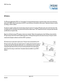
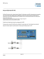
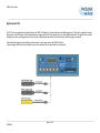
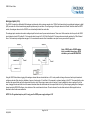
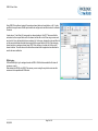
VBOX 3i User Guide VBOX 3iV2 100Hz GPS Data Logger User Guide Page 1 of 46 28/08/2013 VBOX 3i User Guide Page 2 of 46 28/08/2013 VBOX 3i User Guide Contents EC Declaration of Conformity .................................................................................................................................................................. 5 Introduction ............................................................................................................................................................................................... 6 Features ..................................................................................................................................................................................................... 6 Quickstart Guide ....................................................................................................................................................................................... 7 Parts Supplied with VBOX 3i V2 .............................................................................................................................................................. 9 Optional Accessories ............................................................................................................................................................................... 9 Operation ................................................................................................................................................................................................. 10 Power ......................................................................................................................................................................................................................................... 10 Buttons ....................................................................................................................................................................................................................................... 11 Logging ....................................................................................................................................................................................................................................... 12 LED Indicators ............................................................................................................................................................................................................................ 13 Memory Cards ............................................................................................................................................................................................................................ 14 GPS Antenna ............................................................................................................................................................................................................................. 15 Analogue and Digital outputs (AD1 & AD2) ............................................................................................................................................................................... 16 Digital Inputs (D IN) .................................................................................................................................................................................................................... 17 Analogue inputs (A In) ................................................................................................................................................................................................................ 18 RS232 Serial / CAN.................................................................................................................................................................................................................... 20 CAN Pass through...................................................................................................................................................................................................................... 22 Dynamic Modes.......................................................................................................................................................................................................................... 24 Satellite Elevation Mask ............................................................................................................................................................................................................. 24 VBOX Tools Version. ................................................................................................................................................................................................................. 25 USB ............................................................................................................................................................................................................................................ 26 Bluetooth .................................................................................................................................................................................................................................... 26 Audio .......................................................................................................................................................................................................................................... 27 VBOX 3i „.VBO‟ file format ......................................................................................................................................................................................................... 28 VBOXTools Software .............................................................................................................................................................................. 29 Software Installation ................................................................................................................................................................................................................... 29 Local DGPS Basestation ........................................................................................................................................................................ 30 Enabling the DGPS modes. ....................................................................................................................................................................................................... 30 IMU Integration ........................................................................................................................................................................................ 31 Page 3 of 46 28/08/2013 VBOX 3i User Guide Hardware configuration .............................................................................................................................................................................................................. 32 Hardware Set Up ........................................................................................................................................................................................................................ 34 Upgrading the VBOX 3i’s Firmware....................................................................................................................................................... 35 How to Upgrade the Firmware ................................................................................................................................................................................................... 35 Troubleshooting Guide .......................................................................................................................................................................... 36 VBOX 3i V2 Specification ....................................................................................................................................................................... 38 Connection Data ..................................................................................................................................................................................... 40 Analogue Input Connector ..................................................................................................................................................................... 43 CAN Output ................................................................................................................................................................................................................................ 44 Contact Details ........................................................................................................................................................................................ 46 Document Updates..................................................................................................................................................................................................................... 46 Page 4 of 46 28/08/2013 VBOX 3i User Guide EC Declaration of Conformity We declare that this product has been tested to and meet the requirements of: EC Directive 2004/104/EC “Adapting to Technical Progress Council directive 72/245/EEC relating to the radio interference (Electromagnetic Compatibility) of vehicles and amending directive 70/156/EEC on the approximation of the laws of the member states relating to the type-approval of motor vehicles and their trailers.” And has also been assessed, via Technical Construction File, by an independent DTI Competent Body and found to be in conformance with the essential requirements of: EC Directive 89/336/EEC (and amending directives) “Council Directive of 03 May 1989 on the approximation of the laws of the member states relating to electromagnetic compatibility.” DTI Competent Body responsible for issuing certificate of compliance: 3C Test Ltd, Silverstone Technology Park, Silverstone, Northants NN12 8GX Page 5 of 46 28/08/2013 VBOX 3i User Guide Introduction rd The VBOX 3i represents the 3 generation of GPS data logging system from Racelogic. Using a powerful GPS engine, the VBOX 3i can log GPS and other data at 100Hz. The logged data is stored directly onto a compact flash card for easy transfer to a PC. The VBOX 3i also includes 4 high-resolution analogue input channels to record data from external sensors and 2 CAN bus interfaces to allow connection of Racelogic input modules while simultaneously transmitting GPS data on the second bus. In line with previous VBOX models, the VBOX 3i is compatible with all of the existing peripherals including the Multifunction display, ADC03, TC8, FIM03 and Yaw rate sensor. To use the IMU integration feature of the VBOX 3i an IMU02 is required. Features Non-contact 100Hz speed and distance measurement using GPS IMU Integration with GPS data 6.75ms Latency 4 x 24bit synchronous differential analogue inputs ±50v Brake/Event trigger input of 10ns resolution Voice Tagging of Data 2 x CAN Bus interface RS-232 serial interface USB Interface Bluetooth Interface Compact Flash Interface 2 x 16bit User configurable analogue outputs 2 x Digital outputs Brake trigger Input with 100KHz scan rate Wide 7V to 30V operating range *See Note Low current consumption Logging rate selectable from 100Hz, 50Hz, 20Hz, 10Hz, 5Hz, 1Hz Can be used with a differential basestation for positional accuracies of up to 2cm** *RACELOGIC external modules such as Multifunction display only operate from a 12v vehicle supply. Therefore, when using external can modules, VBOX III supply must not exceed 15vDC. **2cm 95% CEP positional accuracy, (requiring RTK VBOX upgrade and RLVBBS3 Basestation) Page 6 of 46 28/08/2013 VBOX 3i User Guide Quickstart Guide Required equipment (All supplied as standard unless specified) VBOX 3i Cigar lighter 12v adapter lead GPS Antenna Blank Compact Flash Card RS232 Cable VBOX Software CD Laptop PC(not supplied) 1. Mount the VBOX 3i GPS antenna in a suitable position on the roof of the vehicle. The ideal position is in the centre of the roof away from any objects that may shadow the GPS signal such as roof bars. This creates a large metal object underneath the antenna to shield it from signals reflected by the ground that can cause multi-path errors. NB: See troubleshooting section if having difficulty obtaining satellite lock. 2. Screw the gold SMA connector on the antenna cable firmly onto the VBOX 3i 'GPS' socket, making sure that the socket on the VBOX 3i is free from any contamination. NB: It is important to connect the antenna to the VBOX 3i before power is connected. The VBOX 3i adjusts the signal gain to the antenna based on the current incoming GPS signal strength. 3. Connect the power connector to the socket marked „PWR‟ on the VBOX 3i. . When power is connected, the red „PWR‟ LED will illuminate and all of the other LEDS will flash once then go off. 4. Allow the VBOX 3i time to acquire satellite lock (This should take no longer than a few minutes.) before moving off to log data. It is good practice to do this at the beginning of your day; after you have done this satellites will be instantly picked up and locked onto, even after periods of the power being switched off or overhead obstructions blocking the view of the sky. If the VBOX 3i has not been used for a long time or if it was last used many miles from its current location, it may take time to find satellite lock. If this situation arises perform a GPS Cold Start to reset the GPS engine. NB: See „Performing a GPS Engine Coldstart‟. Page 7 of 46 28/08/2013 VBOX 3i User Guide 5. The „GPS‟ LED will be lit solid red when no satellite lock has been obtained, once the VBOX 3i gets a lock on visible satellites, the „GPS‟ LED will flash Green to indicate the number satellites. At a normal test track facility you should expect to see between 7 and 12 satellites being received by the VBOX 3i. When the VBOX 3i has a lock on 4 or more satellites then the VBOX 3i is ready to use. NB: If fewer than 7 satellites are consistently seen the position of the GPS antenna on the vehicle may not be ideal, or the nature of the test surroundings may not be ideal; see troubleshooting section on antenna positioning. 6. Now simply drive the vehicle. In the VBOX 3i‟s default mode it will log all data when the vehicle is moving at a speed above 0.5 Kmh and stop recording when the vehicle‟s speed goes below 0.5 kmh. The blue CF LED on the front panel of the VBOX 3i will flash to indicate when data is being logged to the CF card. 7. When you have finished your first test with the VBOX 3i come to a halt, wait until the blue CF LED stops flashing before removing the CF card. Logging can be stopped at any time by pressing the „LOG‟ button to close the current file. NB: If the IMU integration feature of the VBOX 3i is to be used refer to the ‘IMU Integration’ section later in this manual. Page 8 of 46 28/08/2013 VBOX 3i User Guide Parts Supplied with VBOX 3i V2 Description Qty Racelogic Part # VBOX 3i Data logger 1 RLVB3I-V2 Mains Charger/Power Supply 1 2-way LEMO to cigar lighter plug 1m Description Qty Racelogic Part # 5 Way LEMO to 9 Way „D‟ Connector „Serial PC Cable‟ 1 RLCAB001 RLVBACS020 25 Way D Connector 1 ADC25IPCON 1 RLCAB010L VBOX 3i User Manual 1 VB3I-V2MAN GPS Magnetic Antenna 1 RLACS158 Bluetooth Antenna 1 RLACS119 4GB Compact Flash Card 1 RLACS098 USB 2.0 cable 1 RLCAB066-2 PCMCIA CF Adaptor 1 RLACS163 Rigid carry case 1 RLVBACS013V4 VBOX Tools Installation CD 1 RLVBACS030 VBOX 3i Audio Headset 1 RLACS120 Optional Accessories Description Racelogic Part # Description Racelogic Part # Brake Pedal Trigger RLVBACS004 8 Channel Thermocouple Interface RLVBTC8 Hand-held brake trigger RLVBACS009 Can to Analogue Output Module RLVBDAC01 Logging Start/Stop Switch RLVBACS010 Single Yaw Rate Sensor + 2 axis G Sensor RLVBYAW03 Multifunction Display RLVBDSP03 RLVBIMU03 8 Channel (16bit) Analogue Interface RLVBADC03 Inertial Measurement Unit. 3 Yaw Rate Sensors & 3 accelerometers* RTCM DGPS Basestation for 40cm positional accuracy 4 Channel Frequency Input Module RLVBFIM03 RTK DGPS Basestation for 2cm positional accuracy RLVBBS4RG 16 Channel Vehicle CAN Interface RLVBCAN02 RLVBBS4 *RLVBIMU03 required for IMU integration Page 9 of 46 28/08/2013 VBOX 3i User Guide Operation Power Included with the VBOX 3i is a cigar lighter power cable, which is the primary source of power input. This is terminated in a 2-way connector and mates with the 2way „PWR‟ socket on the VBOX 3i. The VBOX 3i can be powered from a wide range of voltage sources, when considering batteries as a power source please note that the minimum operating voltage of the VBOX 3i is 7V. The maximum operating voltage input must not exceed 30V DC. Failure to observe this could result in damage to the VBOX. Warning The VBOX can be connected to other Racelogic input modules including the ADC03, ADC02, TC8, FIM02/3 and Multifunction display. Please note that the voltage supply to Racelogic modules connected to the VBOX will be at the same level as the VBOX power input. Therefore when using any of the Racelogic peripherals with VBOX 3i, the input voltage must not exceed 15 volts. Failure to observe this could result in damage to the module and possibly the VBOX 3i. When running the VBOX from a battery pack, the VBOX will sound a warning tone to indicate when the battery voltage is reaching the minimum operating voltage level. When this tone is heard, the battery pack requires re-charging or replacing. The VBOX 3i has been designed to generate as little heat as possible and it has a wide operating temperature range, however it is good practice to mount the VBOX 3i in a position where it has sufficient airflow around the case. You must connect the GPS antenna before connecting power to the VBOX 3i. This is necessary because on power-up the VBOX 3i will look for a connected GPS antenna and automatically adjust its gain for optimum performance. Page 10 of 46 28/08/2013 VBOX 3i User Guide Buttons VBOX 3i has two membrane buttons on the front panel, LOG and FUNC. LOG is used to start and stop logging to the compact flash card, and FUNC is used to switch between two sample rates, 100Hz and 20Hz. LOG The LOG button will override any of the automatic logging thresholds set in the VBOX. For example, if you have set the VBOX to log all the time, the LOG button will toggle logging on and off. If you have set the VBOX to ‟log only when moving‟ and you are moving, pressing the LOG button will stop the VBOX logging and close the file on the compact flash. Logging will now not continue even if you are moving until the LOG button is pressed again or the compact flash card is removed and reinserted. The VBOX will then continue to log only when moving. Every time the logging is toggled with the LOG button, a new file is created. When the VBOX is logging, the blue CF light flashes. Do not remove the CF card or power down whilst this LED is flashing, if you need to remove the card or power down whilst the CF light is flashing, then press the LOG button first to stop the VBOX logging. FUNC Pressing the FUNC button briefly flashes the LED‟s to indicate the current sample rate. A slow flash (once per second) on all the LED‟s indicates 20Hz, and rapid flashing (5 times a second) indicates a 100Hz sample rate. A running sequence of lights indicates a sample rate other than 100Hz or 20Hz. Pressing and holding the FUNC button for 5 seconds toggles the current sample rate. The sample rate can also be set in the VBOX software. Default setup The default factory settings are restored to the VBOX by pressing and holding the FUNC and LOG buttons for 5 seconds. This will put the VBOX 3i into the default factory settings, 100Hz logging when moving, and the standard logging parameters : sats, time, latitude, longitude, velocity, heading, height, vertical velocity, and brake trigger event time. (DGPS will be off by default.). Page 11 of 46 28/08/2013 VBOX 3i User Guide Logging The VBOX 3i has three Logging modes that are selected and configured via VBOXsetup with the supplied VBOXTools software Logging Modes Log Continuously: With „Log Continuously‟ ticked the VBOX will log data, regardless of movement. Log Only when moving: Without „Log Continuously‟ ticked then the VBOX will only log data to the CF card when it detects speed >0.5Km/h. Advanced: The advanced logging option on the VBOX 3i allows any of the logged data channels to be used to trigger the logging on the VBOX. This is selected and configured through VBOXsetup of the supplied VBOXTools software. This facility allows a threshold value to be set as either > or < so that the logging will start or stop when a data value is exceeded or not. Multiple Data channels can be combined in a Boolean „OR‟ manner to control the logging. Page 12 of 46 28/08/2013 VBOX 3i User Guide LED Indicators There are a series of LED indicators on the front panel of the VBOX 3i, their functionality is as follows: GPS: Flashing Red indicates no satellites in view Flashing Green sequence indicates the number of GPS Satellites currently being tracked. Each flash indicates a satellite with a short pause between each sequence. Flashing Red sequence indicates the number of GLONASS Satellites currently being tracked. Each flash indicates a satellite with a short pause between each sequence. Sequence showing 1 Satellite 1 1 1 1 Sequence showing 4 Satellites Delay 1 2 3 4 Delay 1 2 3 Sequence showing 0 Satellites Delay (Approximately 1 second ) Delay (Approximately 1 second ) Page 13 of 46 28/08/2013 4 VBOX 3i User Guide DIFF: SER: Solid Orange indicates a DGPS lock (either WAAS/EGNOS or 40cm Local DGPS) Solid Green indicates a 2cm „Fixed‟ RTK lock Flashing Yellow indicates that expected incoming CAN data has been decoded properly and is being logged. Flashing Green indicates that there is incoming Serial traffic through this socket. PWR: BLUETOOTH: Solid GREEN indicates that a suitable power source is connected. Solid Red indicates that the VBOX is not ready to operate either because it is still booting up or because there is an error condition. Flashing BLUE indicates Bluetooth is switched on and waiting for a connection. Solid BLUE indicates the VBOX 3i has a Bluetooth connection with another Bluetooth device. Flashes BLUE when data is being written to the card D IN: Solid GREEN indicates that the Brake trigger input has been activated/triggered. CF: CAN: Flashing Yellow indicates that expected incoming CAN data has been decoded properly and is being logged. Flashing Green indicates that there is incoming Serial traffic through this socket. LOG: Lights solid GREEN when data is being logged to the CF card. Flashes RED indicating current logging rate after „FUNC‟ button press, fast for 100Hz, slow for 20Hz Memory Cards The VBOX 3i stores logged data onto CF cards. The CF cards available from Racelogic are already optimised for use on the VBOX 3i and as such do not need formatting before use. Should the CF Card need formatting due to card errors it can be done through Windows, as the VBOX 3i supports the following format type: FAT FAT16 FAT32 Racelogic strongly recommends the following media card brands: SanDisk Kingston Page 14 of 46 28/08/2013 Lexar Ultra PQi VBOX 3i User Guide GPS Antenna The GPS antenna supplied with the VBOX 3i is a 5V active antenna. For the best possible signal quality, it is important to maintain a clean connection between the antenna and the VBOX 3i. Before fixing the antenna to the VBOX 3i, ensure that there are no dust particles in either connector. Replacement antennae are available by contacting your VBOX 3i distributor. The antenna is a magnetic mounting type for quick and simple mounting to the vehicle roof. For optimum GPS signal reception, make sure that the antenna is fitted to the highest point of the vehicle away from any obstructions that may block satellite reception. The GPS antenna works best with a metal ground plane underneath (a metallic vehicle roof is perfect for this). Please also note that when using any GPS equipment, a clear sky view is important. Objects in the surrounding area such as tall buildings or trees can block the GPS signal causing a reduction in the number of satellites being tracked, or introducing reflected signals that can decrease the accuracy of the system. Note that clouds and other atmospheric conditions do not affect the VBOX 3i‟s performance. GPS antennas require a ground plane to operate correctly. This helps to reduce unwanted reflections of the GPS signal caused by nearby objects, and usually the metal roof of a vehicle performs this function. However, if a test requires an antenna to be placed either off the vehicle, or on a vehicle that does not have a metallic roof, a special ground plane antenna must be used. This has an internal ground plane and can operate perfectly without the need for mounting on a metal surface. Ground plane antennas are available from your VBOX 3I distributor. Page 15 of 46 28/08/2013 VBOX 3i User Guide Analogue and Digital outputs (AD1 & AD2) The AD1 and AD2 connectors each have 1 analogue voltage and 1 digital output. The digital output on connector AD2 is a frequency/pulse output corresponding to velocity. The pulse per meter range is adjustable in software. The digital output on connector AD1 is a simple on/off state output. This digital output can be associated with any of the data channels being logged by the VBOX. A threshold level can be set for the selected data channel where a true condition gives a 5v output and a false condition gives a 0v. i.e. Data channel –Speed, threshold 40Km/h. When speed is >40 output = 5V, speed , 40 output = 0V A hysteresis and tolerance value can also be associated to this condition. The default function of this digital output is to indicate the current logging status of the VBOX. The analogue outputs on connectors AD1 and AD2 are both user configurable. For example, analogue output 1 could be configured to output velocity while analogue output 2 might be configured to output lateral acceleration. The voltage range of both analogue outputs is 0 to 5v DC. Page 16 of 46 28/08/2013 VBOX 3i User Guide Digital Inputs (D IN) The „D IN‟ connector contains the two digital inputs for the VBOX 3I. Digital input 1 is also referred to as the Brake trigger input. This input is connected to an event capture input on the GPS engine. This captures precisely the trigger event time (10nS resolution) for use in brake distance calculation. This period of time is called the trigger event time, and is logged and used to correct the measured brake stop distance to the exact point at which the trigger was pressed. A hand-held brake trigger is also available to allow the user to record marker events in the VBOX 3I data file. A remote logging on/off switch is also available for ease of use and when the front panel switch is not accessible. Page 17 of 46 28/08/2013 VBOX 3i User Guide Analogue inputs (A In) The VBOX 3I contains four differential 24bit analogue input channels with a maximum sample rate of 100Hz. Each channel has its own dedicated analogue to digital (A/D) converter with all four channels being sampled synchronously to each other. The voltage range of the input channels is ±50volts. Note that unlike the ADC03 module, the analogue channels in the VBOX 3I are not electrically isolated from each other. The analogue input connector also contains voltage outputs that can be used to power external sensors. These are a Vbatt connection which is equal to the VBOX input voltage level and a DC isolated 5 V Out connection which is equal to 5V ±2%. Both Vbatt and 5V Out connections are internally protected by 100mA thermal fuses. For connector pin configuration see page 16. A screw-terminal connector block is available as an option for easy connection of signal pins. Note: A 25W D-sub to 4W BNC adaptor block is available through your VBOX distributor, part number RLVBACS054 Using the VBOXTools software, logging of the analogue channel data can be switched on or off. It is also possible to change the name of each input channel and configure scale and offset values for calibration of sensors. A scale value of 1 and offset of 0 correspond to a channel reading in Volts DC. This means that the value stored on the compact flash card for the channel will also be in volts. When using a sensor such as a load cell, it may be desirable to store a reading in Kg. In this case, changing the scale and offset to suit the sensor data sheet allows the data stored onto the compact flash to be in Kg. When changing settings for an analogue channel using the VBOX.EXE software, a live data view of the current channel is shown. The value shown is the value after scale and offset is applied and can therefore be used to aid sensor calibration. NOTE: The 5V regulated output on pin16 is only good for VBOX power supply voltages >8.5V Page 18 of 46 28/08/2013 VBOX 3i User Guide Using VBOXTools software, logging of the analogue channel data can be switched on or off. It is also possible to change the name of each input channel and configure scale and offset values for calibration of sensors. A scale value of 1 and offset of 0 correspond to a channel reading in Volts DC. This means that the value stored on the compact flash card for the channel will also be in volts. When using a sensor such as a load cell, it may be desirable to store a reading in Kg. In this case, changing the scale and offset to suit the sensor data sheet allows the data stored onto the compact flash to be in Kg. When changing channel setup for an analogue channel using VBOX Tools software, a live data view of the current channel is shown. The value shown is the value after scale and offset is applied and can therefore be used to aid sensor calibration. 500Hz logging VB3i has the ability to log 4x analogue channels at 500Hz. With this feature enable the file sizes will increase as a result. When loading the VBO file into VBOX Tools ensure you are running the very latest version as older versions are not compatible with 500Hz data. Page 19 of 46 28/08/2013 VBOX 3i User Guide RS232 Serial / CAN VBOX 3i is equipped with 2 CAN Bus interfaces and 2 RS232 serial ports. The primary RS232 port is used for all communication between the VBOX and laptop PC. The primary port is marked RS232 on the VBOX 3i front panel. The primary RS232 port is able to transmit live data from the VBOX to the PC for viewing and performing real-time tests. It is important to note however that due to limitations of the PC serial port, live data transfer of all channels is limited to 20Hz, at 50Hz only standard GPS channels should be transmitted, and at 100Hz only Sats, Time, Speed, and Trigger Event Time should be transmitted. Logging too many channels at too high a rate is likely to cause drop-outs and loss of data. Therefore for maximum accuracy, tests performed at a GPS sample rate above 20Hz should be logged to compact flash and post processed. The secondary RS232 port is used for connection to a Telemetry Radio module allowing the reception of Differential GPS (DGPS) data for local correction from a Racelogic Local DGPS basestation. The secondary RS232 port is located in the connector marked CAN on the VBOX 3i front panel. The CAN Bus ports A and B are located in the VBOX 3i connectors “CAN” and “RS232” respectively. The function of these ports is configurable by the user for use by either Racelogic external modules or the users own CAN Bus equipment. For dual use of RS232 and CAN from one of the sockets you will require a 5Way Lemo splitter RLVBACS024. Power supplied to external Racelogic CAN modules through the “CAN” or “RS232” cables is at the same voltage as the input power supply. Therefore when using Racelogic external CAN modules (eg; MFD or ADC03), the VBOX 3I supply voltage must not exceed 15vDC. Page 20 of 46 28/08/2013 VBOX 3i User Guide VCI CAN input (Vehicle CAN Interface) The VBOX 3i can log up to 16 user defined CAN bus signals on CAN port B. Configuration is performed using the VCI Modules tab under Log Channels in VBOXTools software setup window. CAN signal parameters can be entered manually by the user or imported directly from a CAN database (.DBC) file if available. Racelogic supplies a free encrypted Vehicle CAN Database, giving the user the ability to log basic CAN data from a large number of current vehicles from a broad selection of manufacturers. This CANALLCAR.REF file should be installed as part of the supplied VBOXTools installation. CAN termination The VBOX 3i contains an active termination between 0 Ohms and 120 Ohms, the active terminations are selectable via VBOXTools as shown above right. NOTE: When the Usage of the CAN ports is swapped from one output socket to the other the Termination resistor setting does not follow. So you should check that the Termination is correctly set for the output socket that you are then using. Page 21 of 46 28/08/2013 VBOX 3i User Guide CAN Pass through Ability to output channel data from modules on the secondary bus with user defined identifiers. Eg; VBOX3i can log IMU data on one CAN bus and output the IMU data to third-party equipment on second CAN bus with a user defined identifier. The VBOX3i can output up to 6 CAN messages and 12 CAN channels over the secondary bus. Note: These output CAN channels will be in a 32 bit IEEE float format. 29 bit extended identifiers optional. Page 22 of 46 28/08/2013 VBOX 3i User Guide CANVEL If an input channel is given the name “CANVEL” then the VBOX3i will translate the data of this channel directly through to the GPS speed channel under the following criteria. IMU integration is not enabled and The VBOX3i cannot calculate speed, i.e. no satellite signal (complete satellite drop out) The VBOX3i will scale the input channel to the default speed output format of Km/h according to what the units have been assigned to the substitution speed channel. VBOX3i will recognise the following unit names: MPH KM/H KPH Knots m/s ms-1 Note: If no UNITS have been assigned to the input channel then VBOX3i will assume that it is KPH This function is useful while testing around built up areas or driving under large bridges. Page 23 of 46 28/08/2013 VBOX 3i User Guide Dynamic Modes The VBOX3iSL has three Dynamic modes. These Dynamic modes directly change the SMI smoothing index applied by the GPS engine to all Doppler-derived data, notably speed and heading. The lower smoothing levels have a higher dynamic response but are adversely noisier. The three options are: High Dynamics: The „High dynamics‟ setting should be used for high accuracy Trigger Brake Stops or any test where time and distance are critical and the vehicle test incorporates highly dynamic manoeuvres. Normal: The „Normal‟ mode should only be used for any testing that does not involve any high dynamic manoeuvres. Low Dynamics: The „Low dynamics‟ mode can be used for smoother velocity and heading data and less acceleration noise only in lower dynamic tests. Page 24 of 46 28/08/2013 VBOX 3i User Guide Satellite Elevation Mask This feature can be used to improve GPS signal quality when nearby obstacles like trees and building are reflecting or temporarily obscuring the signal from satellites at low elevation. Raising the mask will cause the GPS engine to ignore satellites below the mask angle, so must be used carefully as it also reduces the total number of received satellites. The elevation mask angle can be changed in the GPS section within VBOX Tools Setup. VBOX Tools Version 2.2.2b42 and above now has an option to change the SEM value for the VBOX 3i series. Page 25 of 46 28/08/2013 VBOX 3i User Guide USB The VBOX 3i includes an USB 2.0 connection that can be used for VBOX configuration and the output of real-time VBOX 3i serial data at the full 100Hz data rate. Ensure that before you connect your VBOX 3i to your PC that you have installed the supplied VBOXTools software, as this will also put the required USB drivers onto your PC. The VBOXTools software installation will place the VBOX 3i USB drivers in the following location on your computer. C:\program files\Racelogic\Drivers These drivers can also be found on the actual VBOXTools installation CD. When you connect you powered up VBOX 3i to your PC with the supplied RLVBCAB066 USB A to USB mini lead your PC will recognise the presence of new hardware and open the typical Windows install window for new hardware Follow the on screen prompts and point the Windows installation to the location of your drivers. Note: USB drivers are available on the Racelogic website, also installed into C:\program files\Racelogic\Drivers after VBOX Tools installation. Bluetooth The VBOX 3i comes equipped with a Bluetooth Radio allowing configuration of the VBOX remotely along with remote output of real-time VBOX 3i serial data, at the full 100Hz data rate, to any Bluetooth capable PC or Data logger. Pairing your computer with the VBOX 3i The VBOX3i will need the Bluetooth antenna connected and the computer will require a Bluetooth module or dongle to establish a virtual connection. VBOX3i will connect to the computer via SPP (Serial Port Profile) this can be done as a secure or unsecure connection. Note: Pairing code for secure connection is 1234 Page 26 of 46 28/08/2013 VBOX 3i User Guide Audio Voice Tagging The VBOX 3i has the ability to record audio tags with a GPS „synched‟ timestamp accuracy of 0.5 secs along with the .VBO data file. Voice notes regarding test conditions or erroneous runs can be recorded, which can be replayed instantly when viewing logged files in the Graph facility of the VBOXTools software. A WAV file will be recorded onto the CF card along with the normal VBOX data file. The supplied Headset/Microphone includes a switch, which is used to start and stop the recording of an audio tag. Recording a Sound Wav Pressing the headset switch once will sound an audible beep, through the headset, to confirm that recording of the WAV file has begun. Pressing the switch for a second time will then stop recording, this will be confirmed by a second beep through the headset. If the switch has only been pressed once the VBOX 3i will record for 30 seconds then automatically stop recording. Replaying Voice tags in VBOXTools When a logged VBOX data file .vbo is loaded into VBOXTools and displayed in the Graph screen any associated WAV files will appear in the speed data trace as green circles provided that the logged file is in the same folder as the loaded VBOX data file. Play the associated WAV file by clicking the Green circle. NOTE: if a Red circle is seen on the graph screen in VBOXTools then the associated WAV file is not present in the same folder as the loaded VBOX data file. Page 27 of 46 28/08/2013 VBOX 3i User Guide VBOX 3i ‘.VBO’ file format The VBOX 3i data files are saved in standard space de-limited text format. This allows the data to easily be imported into third party applications such as word processors or spreadsheets. The files each contain a header section before the main data that describes the channel content and information about the VBOXIII such as serial number and firmware version. The [Column names] parameter specifies the data in each column of the data section. An example of a VBOX 3i VBO file is shown on the right. Page 28 of 46 28/08/2013 VBOX 3i User Guide VBOXTools Software The VBOXTools software is used for configuration of the VBOX 3i and also for analysis of the VBO data files. For further information on the VBOXTools software refer to the VBOXTools user manual supplied with VBOX 3i. Software Installation The VBOX 3i setup software must be installed onto the hard drive of a computer; it cannot be run from the installation CD. To install the software insert the CD into the CD drive of your computer. The default installation language is English. Press „OK‟ to continue, then follow the on-screen instructions to complete the installation. The VBOX 3i setup software is not limited to one user or computer and can be installed on multiple workstations if so desired. Page 29 of 46 28/08/2013 VBOX 3i User Guide Local DGPS Basestation When the VBOX 3i is used in conjunction with a Local DGPS Basestation the positional accuracy can be improved from the standard 3m 95% CEP. There are two available Basestation options: 40cm Positional accuracy: If the VBOX 3i is used with a RLVBBS2 then the positional accuracy is increased to 40cm 95% CEP. The height accuracy is improved to 1M 95%CEP 2cm Positional accuracy: If the VBOX 3i has an RTK upgrade option installed and is used with a RLVBBS4RG then the positional accuracy is increased to 2cm. - Racelogic proprietary 2cm correction (Not compatible with VB3i-SL RTK) CMR 2cm correction (Trimble standard message type) RTCMv3 2cm correction (RTCM standard message type) RECOMMENDED RTCMv3 is recommended as the default RTK 2cm correction type. This message format is a globally recognised type and more resilient to data loss caused by radio errors. Note: RLVBOX 3iR2G2 has a max log rate of 20Hz when in RTK mode. RLVBOX 3iR10G10 & RLVB3i-SL RTK has a max log rate of 100Hz when in RTK mode. Enabling the DGPS modes. The VBOX must have the correct DGPS mode enabled in VBOX Tools or VBOX Manager before it is capable of receiving and using the DGPS correction information transmitted by a Local Basestation. Run the latest VBOXTools software Enter the VBOX setup screen and go to the GPS page Click on the DGPS button and select the correct DGPS mode from the available option Close the VBOX setup screen. Page 30 of 46 28/08/2013 VBOX 3i User Guide IMU Integration IMU integration should not be enabled for measurement of Braking distances The main purpose of integrated navigation systems is to take advantage of the complementary attributes of two or more navigation systems (GPS and Inertial motion unit) to achieve far better performance than through the use of either system on its own. GPS derives data through two separate methods, Doppler (speed, vertical speed and heading) and Triangulation (latitude longitude and height). The Triangulation calculated position data is bounded by an error (CEP value), which depends on the quality of the GPS receiver and its environment. GPS measurements are stable but rely on weak signals, which are subject to signal blockage and interference from the surrounding environment, resulting in poor performance. The quality of the Doppler derived channels are also affected in a similar way by the same influential factors. Inertial sensor measurements on the other hand are continuously available but suffer from long-term drift due to the accumulation of integration errors of the accelerometer and gyro measurements. As a result the IMU derived position error increases without bounds. IMU‟s of a higher accuracy are available but tend to be large, bulky and expensive. These complementary properties of IMU and GPS data make them ideal candidates for integration and can accurately compensate for GPS dropouts or noise. The VBOX 3i has the capability of integrating the GPS data with inertial data from the IMU02 Inertial Measurement Unit allowing accurate smoothing of the following parameters: Latitude Velocity Height Longitude Heading Vertical Velocity To use the data from a connected IMU to perform integrated Kalman filtering the VBOX 3i first needs to be set up using VBox Tools. The screen shots here show the new IMU integrated Speed in blue and the non-integrated raw speed in red. In these screen shots you can see how the IMU integrated Speed has continued to be produced perfectly through noisy and full dropout conditions Page 31 of 46 28/08/2013 VBOX 3i User Guide Hardware configuration First the VBOX 3i needs to be configured to use the IMU data from the IMU03 it is connected to. 1. Connect the IMU to the CAN port of the VBOX 3i with the required cable and power the VBOX 3i. 2. Open VBOX Tools and connect the computer to the VBOX 3i using either serial, USB or Bluetooth. 3. Select the appropriate COM port. The „serial data OK‟ message should appear in green beneath the COM port number. 4. Click on the „VBOX Setup‟ button to open the VBOX setup window. 5. Underneath the “Channels” tab a „3-axis Modules‟ tab should be visible. This indicates the IMU has been correctly detected by the VBOX 3i. 6. If the „3 axis Modules‟ tab is not visible, click on the „CAN‟ button at the top of the window. 7. Make sure that the „Racelogic CAN Modules only‟ (red) is assigned to the CAN port that the IMU is connected to. 8. Exit setup, then re-enter. This should correctly detect the presence of the IMU data should the ports have previously been swapped. NB: If the IMU tab has still not appeared under channels, the IMU settings should be checked to make sure it is transmitting data at the correct baud rate and is configured correctly. If the LED above the CAN port is not lit green the CAN messages from the IMU are not being understood by the VBOX 3i and it is likely the IMU configuration is incorrect. Page 32 of 46 28/08/2013 VBOX 3i User Guide 9. Next click on the GPS button. Under the Kalman Filter section check the „Use IMU‟ box. 10. The VBOX 3i will now use the inertial data transmitted by the connected IMU and integrate it with the GPS data to generate filtered and smoothed data speed, heading and position data. NB: If no IMU is currently connected, the data logged by the VBOX 3i will be the raw unfiltered GPS data. If however an IMU is connected after the VBOX 3i has begun to log data the file will contain a mix of unfiltered and filtered data. 11. Once the VBOX 3i has been set up to use the IMU data it will automatically log to CF card the Speed Quality, IMU Kalman Filter Status and IMU channels. These channels allow Racelogic to troubleshoot any problems that may be encountered with the Kalman filter generated data and cannot be switched off. If the IMU channels need to be made available for viewing live in VBOX Tools click on the „Check All‟ button under „Send over serial‟. Page 33 of 46 28/08/2013 VBOX 3i User Guide Hardware Set Up 1. Setup the VBOX 3i in the vehicle as you would normally. 2. A laptop or Q1 connected to the VBOX 3i is required for the setup of the IMU to view the live X-accel and Y-accel values. 3. Position the vehicle on flat ground with the engine off but the ignition on to allow the VBOX 3i to remain powered. This prevents engine vibration creating erroneous IMU readings during IMU setup. 4. The IMU should be placed along the centreline of the vehicle and fixed in position to prevent it from moving around while the vehicle is in motion. Use a mounting procedure that allows small movement in the X and Y planes in order align the IMU perfectly. If available a tilt table can be used to accurately align the IMU to ensure the Kalman filter uses IMU data that is as accurately aligned with the vehicle. 5. Adjust the position of the IMU while observing the resulting change of the IMU X-accel and Y-accel values on a live display in VBOX Tools. By changing the position of the IMU in Pitch and Roll it should be possible to achieve values of X-accel and Y-accel very close to zero. For the best possible IMU integration results the IMU should be aligned so that the X and Y-accel values are 0g +/-0.01g NB: The IMU accelerations where chosen as the main setup input as using the X-accel and Y-accel values assumes that the IMU sensors are aligned as close to zero as possible and any errors introduced by sensor alignment will be small for the range of angles the IMU is likely to encounter. NB: Positive Pitch equates to a positive Longitudinal Acceleration, Positive Roll angle equates to a positive Lateral Acceleration. Page 34 of 46 28/08/2013 VBOX 3i User Guide Upgrading the VBOX 3i’s Firmware Occasionally Racelogic releases new versions of firmware (internal code) for VBOX 3i products, often to introduce new features. New firmware is loaded into the VBOX 3i using a computer and a CF card. The latest firmware upgrade file for the VBOX 3i is available from the Racelogic website in the „Support‟ section. http://www.racelogic.co.uk If you need the latest update file, download it from the website and copy it to your CF card How to Upgrade the Firmware To upgrade the firmware power the VBOX 3i and wait until the box has finished initialisation. Insert the CF card containing the upgrade file. Once the upgrade is complete the VBOX 3i will beep twice and resume normal operation. Once the upgrade is complete the upgrade file will be erased and a report file will be generated. If the upgrade fails for any reason the upgrade file remains on the card and the VBOX 3i retains the previous version of firmware. Once the firmware upgrade has completed successfully, the VBOX 3I should be power cycled before use. If you have any questions regarding the VBOX 3i upgrade procedure, please do not hesitate to contact: [email protected] Page 35 of 46 28/08/2013 VBOX 3i User Guide Troubleshooting Guide Trouble Locking onto Satellites If the VBOX 3i is having trouble locking onto satellites then please follow the checklist below for typical solutions: Ensure that the antenna is placed in a position where it has an unobstructed view of the sky. (See „GPS Antenna Placement‟ below) Check the antenna connection with the VBOX 3i; only small amounts of dirt in the socket can cause a significant reduction in signal strength. Also check the cable at the plug and along its length for any damage. Check that the power supply is connected and free from damage. If possible try another known working antenna, to confirm antenna functionality. Perform a GPS Coldstart and then leave the unit powered up in an open static position for at least 15 minutes. See „VBOX 3i not responding‟ below. Once the VBOX 3i has locked on to 4 or more satellites it will be ready for use. No Communication with PC If the red LED on the front of the VBOX 3i is not illuminated then there is no power to the unit; check that battery contains adequate charge or, if using a cigar lighter, check internal cigar lighter fuse. Check that the correct COM port has been selected in VBOXTools Check that no other programs are using the same COM port. Disconnect the power to the VBOX 3i then reconnect it. COM Port Unavailable The computer may have been started with a different VBOX 3i connected to it; disconnect the VBOX 3i, restart the computer then reconnect the VBOX 3i. Another software package installed on your computer may have reserved the COM port. No Data is logged to the VBO file Check satellite reception. Loss of reception may prevent data from being logged to the card (dependent on logging mode). Page 36 of 46 28/08/2013 VBOX 3i User Guide VBOX 3i not responding - GPS Coldstart The GPS engine has locked up. Perform a GPS Engine Coldstart A GPS coldstart forces the GPS engine to reset its downloaded almanac of current satellite positions. This can be useful if the VBOX 3i is having trouble locking onto satellites, which typically occurs if the VBOX 3i has not been used for several weeks or if it was last used a long distance (over one thousand miles) away from the current location. After performing a GPS coldstart leave the VBOX 3i powered up in a static location where the antenna has an unobstructed view of the skies until the „GPS‟ LED becomes solid green. Once the VBOX 3i has downloaded the new almanac it will reacquire satellites in noisy situations (such as near trees, buildings and under bridges) much more quickly. It will also acquire satellite much more quickly on power-up. To perform a GPS coldstart on the VBOX 3i perform the following actions: Press and hold the „LOG‟ button on the front of the VBOX 3i for five seconds until a long beep is sounded. When the button is released the „GPS‟ LED will start to flash red showing that the Coldstart has been performed and the GPS engine is now not locked onto any satellites. After approximately 30-45 secs the „GPS‟ LED will start to flash green indicating that satellite lock has been achieved and indicating the number of satellites that it is locked onto. Page 37 of 46 28/08/2013 VBOX 3i User Guide VBOX 3i V2 Specification GPS Velocity Accuracy Distance Accuracy 0.05% (<50cm per Km) Units Update rate Resolution Height accuracy Height accuracy with DGPS Metres / Feet 100Hz 1cm 6 Metres 95% CEP** 2 Metres 95% CEP** Brake Stop Accuracy Accuracy +/- 2cm Time Resolution Accuracy 0.01 s 0.01 s Units Update rate Maximum velocity Minimum velocity Resolution Latency 0.1 Km/h (averaged over 4 samples) Km/h or Mph 100 Hz 1000 Mph 0.1 Km/h 0.01 Km/h 6.75ms Absolute Positioning Accuracy Accuracy with SBAS DGPS Accuracy with RTCM DGPS Accuracy with RTK DGPS*** Update rate Resolution 3m 95% CEP** >1m 95% CEP** 40cm 95% CEP** 2cm 95% CEP** 100 Hz 1.8mm Heading Resolution Accuracy 0.01° 0.1° Power Input Voltage range Power 7v-30v DC Max 5.5 watts Acceleration Accuracy Maximum Resolution Update rate 0.5% 20 G 0.01 G 100Hz Environmental and physical Weight Size Operating temperature Storage temperature Approx 900 grammes 170mm x 121mm x 41mm -20C to +70C -30C to +80C Memory Compact Flash Recording time Type I Dependent on flash card capacity* *Approximately 29Mb per hour used when logging GPS data at 100Hz Approx 182Mb per hour total logging capacity Definitions ** CEP = Circle of Error Probable 95% CEP (Circle Error Probable) means 95% of the time the position readings will fall within a circle of the stated diameter Page 38 of 46 28/08/2013 VBOX 3i User Guide Outputs CAN Bus Bit rate Identifier type Data available Analogue Voltage range Default setting * Accuracy Update rate 125Kbits, 250Kbits, 500Kbits & 1Mbit selectable baud rate Standard 11bit 2.0A Satellites in View, Latitude, Longitude, Velocity, Heading, Altitude, Vertical velocity, Distance, Longitudinal acceleration & lateral acceleration, Distance from trigger, Trigger time, trigger Velocity 0 to 5Volts DC Velocity 0.0125Volts per Km/h (0 to 400Km/h) 0.1 Km/h 100Hz Digital Frequency range Default setting * DC to 44.4Khz 25Hz per Km/h (0 to 400Km/h) Accuracy Update rate 90 pulses per metre 0.1Km/h 100Hz * The range settings can be adjusted by the user in software Inputs CAN Bus Racelogic modules External CAN Bus Up to 32 channels from any combination of ADC02, ADC03, FIM02, TC8, Yaw sensor or CAN01. Limited to 16 with the Kalman Filter enabled 16 Channels of user definable CAN signal from external bus. Eg; vehicle CAN bus Can load signal data from industry standard DBC database file. Analogue Number Channels Input range Channel Sample order 4 ±50v Synchronous Digital Brake/Event Trigger On/Off Logging control 10ns resolution Remote log control from hand-held switch Resolution DC Accuracy Page 39 of 46 28/08/2013 24 bit 400 μV VBOX 3i User Guide Connection Data Front View of VBOX3i V2 2 pin LEMO socket 3 pin LEMO socket Page 40 of 46 28/08/2013 5 pin LEMO socket VBOX 3i User Guide Connector PIN 1 2 1 POWER In/Out Description I Power + I Ground Type Connector PIN 1 2 3 2 AD 1 In/Out O O I Type Connector PIN 1 2 3 3 AD 2 In/Out O O I Type Description Analogue 2 Output Digital 1 Output Lemo 3 pin Connector PIN 1 2 4 D IN In/Out I I Type Lemo 3 pin 3 I Range 7V to 30V 0V Lemo 3 pin Description Analogue 1 Output Digital 2 Output Ground Range 0V to 5V 0V to 5V Range 0V to 5V 0V to 5V Description Ground Digital Input 2. Start/Stop Logging Digital Input 1. Brake Trigger Page 41 of 46 28/08/2013 Lemo 2 pin Range 0V to 5V (14v tolerant) 0V to 5V (14v tolerant) VBOX 3i User Guide Connector PIN 1 2 3 4 5 5 CAN In/Out O I I/O I/O O Type Description RS232 Tx (PORT B) RS232 Rx (PORT B) CAN Bus High (PORT A) CAN Bus Low (PORT A) +V Power Lemo 5 pin Connector PIN 1 2 3 4 5 6 SER In/Out O I I/O I/O O Type Description RS232 Tx (PORT A) RS232 Rx (PORT A) CAN Bus High PORT B) CAN Bus Low (PORT B) +V Power Lemo 5 pin Connector PIN Center Chassis ANT In/Out - Range 12v 12v Same as Power + Range 12v 12v Same as Power + Antenna connector Type Description RF Signal / Power for active antenna Ground Page 42 of 46 28/08/2013 SMA Range VBOX 3i User Guide Analogue Input Connector View of Socket on VBOX III Connector: Analogue PIN In/Out 1 I 2 I 3 I 4 I 5 I 6 I 7 I 8 I 9 10 11 12 13 Type: Sub-D 25-way Socket Description Range Channel 1 + Channel 1 Channel 2 + Channel 2 Channel 3 + Channel 3 Channel 4 + Channel 4 - Connector: Analogue PIN In/Out 14 O 15 O 16 O 17 O 18 19 20 21 22 23 24 25 Note: A screw terminal connector block is available to purchase on request from your VBOX supplier. Page 43 of 46 28/08/2013 Type: Sub-D 25-way Socket Description Range Vbatt Equal to Input Voltage. 100mA GND Iso. 5 V Out Isolated 5V ±2%. 100mA Iso. GND Isolated Ground VBOX 3i User Guide CAN Output The VBOX 3i has a CAN output which is present on the 5-way connector output; Data format: Motorola; Baud rate: 500Kb/s. Format ID** 0x301 Update rate * 10ms 0x302 0x303 0x304 0x305 0x306 0x307 0x308 0x309 10ms 10ms 10ms 10ms 10ms 10ms 10ms 10ms Motorola Data Bytes 1 2 3 4 5 6 7 8 (1) Sats in (2) Time since midnight UTC (3) Position – Latitude MMMM.MMMMM view (4) Position – Longitude MMMMM.MMMMM (5) Velocity. (Knots) (6) Heading. (Degrees) (7) Altitude. WGS 84. (Metres) (8) Vertical velocity. (M/S) Unused (9) Status (10) Status (11) Distance. (Meters) (12) Longitudinal Accel. (G) (13) Lateral Accel. (G) (14) Distance travelled since VBOX reset (15) Trigger time (16) Trigger Velocity (17) Velocity Quality Unused Unused Unused Unused Unused Unused Unused (18) Position latitude (19) Status (20) Position longitude Unused Page 44 of 46 28/08/2013 VBOX 3i User Guide *Update rate depends on GPS update rate. 10ms Update rate shown corresponds to 100Hz GPS setting. **Default Identifiers. The identifier values can be changed using the configuration software. (1) If Satellites in view < 3 then only Identifier 0x301 transmitted and bytes 2 to 8 are set to 0x00. (2) Time since midnight. This is a count of 10mS intervals since midnight UTC. (5383690 = 53836.90 seconds since midnight or 14 hours, 57 minutes and 16.90 seconds) (3) Position, Latitude * 100,000 (311924579 = 51 Degrees, 59.24579 Minutes North). This is a true 32bit signed integer, North being positive. (4) Position, Longitude * 100,000 (11882246 = 1 Degrees, 58.82246 Minutes West). This is a true 32bit signed integer, West being positive. (5) Velocity, 0.01 knots per bit. (6) Heading, 0.01 per bit. (7) Altitude, 0.01 meters per bit, signed. (8) Vertical Velocity, 0.01 m/s per bit, signed. (9) Status. 8 bit unsigned char. Bit 0=VBOX Lite, Bit 1=Open or Closed CAN Bus (1=open), 2=VBOX3 (10) Status is an 8 bit unsigned char. Bit 0 is always set, Bit 3=brake test started, Bit 4 = Brake trigger active, Bit 5 = DGPS active (11) Distance, 0.000078125 meters per bit, unsigned. Corrected to trigger point. (12) Longitudinal Acceleration, 0.01G per bit, signed. (13) Lateral Acceleration, 0.01G per bit, signed. (14) Distance travelled in meters since VBOX reset. (15) Time from last brake trigger event. 0.01 Seconds per bit. (16) Velocity at brake trigger point in Knots. (17) Velocity Quality, 0.01 km/h per bit. (18) Position, Latitude 48bit signed integer, Latitude * 10,000,000 (minutes). North being positive. (19) Bit 0 = Kalman filter status (20) Position, Longitude 48bit signed integer, Longitude * 10,000,000 (minutes). East being positive. The VBOX CAN database is available in Vector Database (DBC File) format on request from Racelogic Page 45 of 46 28/08/2013 VBOX 3i User Guide Contact Details Racelogic Unit 10 Swan Business Centre Osier Way Buckingham Bucks MK18 1TB United Kingdom Email: [email protected] Web: www.racelogic.co.uk Document Updates Rev Date Changes Init Page Change Draft 28-Jan-09 -- Draft Version of Document. AM 1 29-April-09 31 - 34 IMU integration setup added AM 2 6-May-09 34 Change to Pitch and Roll statement in IMU integrations section KB 3 11-May-09 37 Update to GPS description of coldstart procedure KB 4 08-Dec-09 17 Update to AD1 and AD2 function 5 01-Mar-11 multiple General update of text and images SG 6 13-Jan-12 multiple Image updates LN 7 07-Mar-12 multiple Change manual from VB3i to VB3i V2 LN 8 28-May-12 44-45 Update CAN Output information SN 9 27-Aug-13 9 Parts supplied table update SN Page 46 of 46 28/08/2013