1
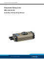
Translation of the original manual Pneumatic Rotary Unit SRU-mini 8-14 Assembly and Operating Manual Superior Clamping and Gripping Imprint Imprint Copyright: This manual remains the copyrighted property of SCHUNK GmbH & Co. KG. It is solely supplied to our customers and operators of our products and forms part of the product. This documentation may not be duplicated or made accessible to third parties, in particular competitive companies, without our prior permission. Technical changes: We reserve the right to make alterations for the purpose of technical improvement. Document number: 0389439 Edition: 08.03 |07/11/2014|en © SCHUNK GmbH & Co. KG All rights reserved. Dear customer, congratulations on choosing a SCHUNK product. By choosing SCHUNK, you have opted for the highest precision, top quality and best service. You are going to increase the process reliability of your production and achieve best machining results – to the customer's complete satisfaction. SCHUNK products are inspiring. Our detailed assembly and operation manual will support you. Do you have further questions? You may contact us at any time – even after purchase. Kindest Regards Yours SCHUNK GmbH & Co. KG Spann- und Greiftechnik Bahnhofstr. 106 – 134 D-74348 Lauffen/Neckar Tel. +49-7133-103-0 Fax +49-7133-103-2399 [email protected] www.schunk.com 2 08.03|SRU-mini 8-14|en Table of contents Table of contents 1 About this manual .................................................................................................... 5 1.1 Warnings ................................................................................................................... 5 1.2 Applicable documents .............................................................................................. 6 2 Basic safety notes .................................................................................................... 7 2.1 Intended use ............................................................................................................. 7 2.2 Not intended use ...................................................................................................... 7 2.3 Environmental and operating conditions................................................................. 7 2.4 Product safety........................................................................................................... 8 2.4.1 Protective equipment ................................................................................... 8 2.4.2 Constructional changes, attachments, or modifications .............................. 8 2.5 Personnel qualification ............................................................................................. 8 2.6 Using personal protective equipment...................................................................... 8 2.7 Notes on particular risks........................................................................................... 9 3 Warranty ................................................................................................................. 10 4 Scope of delivery ..................................................................................................... 11 5 Accessories .............................................................................................................. 11 5.1 Sensors.................................................................................................................... 11 6 Technical data ......................................................................................................... 12 7 Assembly ................................................................................................................. 13 7.1 Mechanical connection .......................................................................................... 13 7.2 Air connection ........................................................................................................ 15 7.3 Adjustment of the end positions ............................................................................ 17 7.4 Adjustment of the shock absorber stroke (Variant H) ........................................... 18 7.5 Adjustment of the shock absorber stroke (Variant S)............................................ 19 7.6 Adjustment of the central position (Variant M) .................................................... 20 7.7 Sensors.................................................................................................................... 21 7.7.1 MMS 22 magnetic switch ............................................................................ 21 8 Commissioning ........................................................................................................ 23 8.1 Setting the speed .................................................................................................... 23 8.2 Adjustment of the shock absorber stroke.............................................................. 25 9 Trouble shooting ..................................................................................................... 26 9.1 Module does not move? ........................................................................................ 26 9.2 The module does not travel through the entire stroke? ....................................... 26 9.3 The module rotates abruptly? ................................................................................ 27 9.4 Torque diminishes? ................................................................................................ 27 08.03|SRU-mini 8-14|en 3 Table of contents 10 Maintenance and care ............................................................................................. 28 10.1 Notes....................................................................................................................... 28 10.2 Maintenance and lubrication intervals. ................................................................. 28 10.3 Lubricants/Lubrication points (basic lubrication) ................................................. 28 10.4 Disassembly of the module ................................................................................... 29 10.5 Servicing and assembling the module .................................................................... 29 10.5.1 Screw tightening torques ............................................................................ 30 11 Assembly drawing ................................................................................................... 31 12 Seal kit .................................................................................................................... 33 13 Translation of original declaration of incorporation ................................................. 35 4 08.03|SRU-mini 8-14|en About this manual 1 About this manual This instruction is an integral part of the product and contains important information for a safe and proper assembly, commissioning, operation, maintenance and help for easier trouble shooting. Before using the product, read and note the instructions, especially the chapter "Basic safety notes". 1.1 Warnings To make risks clear, the following signal words and symbols are used for safety notes. DANGER Danger for persons. Non-compliance will inevitably cause irreversible injury or death. WARNING Dangers for persons. Ignoring a safety note like this can lead to irreversible injury and even death. CAUTION Dangers for persons. Non-observance can cause minor injuries. NOTICE Material damage Information about avoiding material damage. DANGER Danger of explosion in potentially explosive areas! 08.03|SRU-mini 8-14|en 5 About this manual 1.2 Applicable documents • General terms of business • Catalog data sheet of the purchased product • Assembly and Operating manuals of the accessories • Supplementary sheet "Installation and operating instructions - EX" The documents listed here, can be downloaded on our homepage www.schunk.com 6 08.03|SRU-mini 8-14|en Basic safety notes 2 Basic safety notes 2.1 Intended use The product was designed to swivel permissible attachments or workpieces. The product is intended for installation in a machine/system. The requirements of the applicable guidelines must be observed and complied with. The product may be used only in the context of its defined application parameters ( 6, Page 12). The product is designed for industrial use. To use this unit as intended, it is also essential to observe the technical data and installation and operation notes in this manual and to comply with the maintenance intervals. 2.2 Not intended use Use which is not specified as an intended use is for instance when the product is for example used as a pressing tool, stamping tool, lifting tool, guide for tools, cutting tool, tensioning mean, boring tool. 2.3 Environmental and operating conditions • Make sure that the product has a sufficient size for the application. • Observe Maintenance and lubrication intervals ( 10.2, Page 28). • Make sure that the environment is free from splash water and vapors as well as from abrasion or processing dust. Exceptions are products that are designed especially for contaminated environments. 08.03|SRU-mini 8-14|en 7 Basic safety notes 2.4 Product safety Dangers arise from the product, if: • the product is not used in accordance with its intended purpose. • the product is not installed or maintained properly. • the safety and installation notes are not observed. Avoid any manner of working that may interfere with the function and operational safety of the product. Wear protective equipment. NOTE More information are contained in the relevant chapters. 2.4.1 Protective equipment Provide protective equipment per EC Machinery Directive. 2.4.2 Constructional changes, attachments, or modifications Additional drill holes, threads, or attachments that are not offered as accessories by SCHUNK may be attached only with permission of SCHUNK. 2.5 Personnel qualification The assembly, initial commissioning, maintenance, and repair of the product may be performed only by trained specialist personnel. Every person called upon by the operator to work on the product must have read and understood the complete assembly and operating manual, especially the chapter "Basic safety notes" ( 2, Page 7). This applies particularly to personnel only used occasionally, such as maintenance personnel. 2.6 Using personal protective equipment When using this product, observe the relevant industrial safety regulations and use the personal protective equipment (PPE) required! • Use protective gloves, safety shoes and safety goggles. • Observe safe distances. • Minimal safety requirements for the use of equipment. 8 08.03|SRU-mini 8-14|en Basic safety notes 2.7 Notes on particular risks Generally valid: • Remove the energy supplies before installation, modification, maintenance, or adjustment work. • Make sure that no residual energy remains in the system. • Do not move parts by hand when the energy supply is connected. • Do not reach into the open mechanism or the movement area of the unit. • Perform maintenance, modifications, and additions outside the danger zone. • Secure the product during all operations against uncontrolled activation. • Take a precautionary approach by maintenance and disassembly. • Only specially trained staff should disassemble the product. WARNING Risk of injury from objects falling and being ejected • The danger zone must be surrounded by a safety fence during operation. WARNING Risk of injury due to rotating components! Avoidance: The danger zone must be surrounded by a safety fence during operation. 08.03|SRU-mini 8-14|en 9 Accessories 3 Warranty If the product is used as intended, the warranty is valid for 24 months from the date of delivery from the production facility under the following conditions: • Intended use in 1-shift operation • Observe the mandatory maintenance and lubrication intervals • Observe the environmental and operating conditions Parts touching the work piece and wear parts are not part of the warranty. 10 08.03|SRU-mini 8-14|en Accessories 4 Scope of delivery The scope of delivery includes • Pneumatic Rotary Unit SRU in the ordered model. • Accessory pack 5 Accessories A wide range of accessories is available for this module. For information about which accessories can be used with the appropriate product version ☞ catalog. 5.1 Sensors Overview of the compatible sensors Designation Type Magnetic switch MMS • Exact type designation of the compatible sensors see ☞ catalog. • If you require information on sensor operation, contact your SCHUNK contact person or download information from our homepage. www.schunk.com 08.03|SRU-mini 8-14|en 11 Technical data 6 Technical data Mechanical operating data Angle of rotation [°] 180 Adjustability of end positions Min. -3 Max. +90 Repeatability [mm] < 0.07 Ambient temperature [°C] Min. -10 Max. (with shock absorber) +60 Max. (without shock absorber) +90 Relative humidity Min. 35 Max. (condensation-free) 85 IP rating 65 Noise emission [dB(A)] ≤ 70 Operating data for media connection Pressure medium Compressed air, compressed air quality according to ISO 8573-1:7 4 4 Min. pressure [bar] 4.5 Max. pressure [bar] 8 More technical data are included in the catalog data sheet. Whichever is the latest version. 12 08.03|SRU-mini 8-14|en Assembly 7 Assembly 7.1 Mechanical connection WARNING Warning: Risk of injury when the machine/system moves unexpectedly! Remove the energy supplies before starting with assembly and adjustments. Make sure that no residual energy remains in the system. Check the evenness The values relate to the entire bolting surface. of the bolting surface Requirements for levelness of the bolting surface (Dimensions in mm) Diameter < 100 > 100 Permissible unevenness < 0.02 < 0.05 NOTICE Risk of damage to the bearings! • Insert the centering pins by hands. • Assembly and disassembly the pins without forces. 08.03|SRU-mini 8-14|en 13 Assembly Mounting The module can be mounted from the top, from the bottom or from the side. Fig. 1 Assembly options Mounting material Item SRU Designation 8 Ø5 M2.5 / 25 deep Ø3 x 8 91 Centering sleeves 92 2 Screws for mounting from the top (output side) Cylindrical pin for locating the adapter plate Screws for mounting form the bottom (floor side) Screws for side mouting 3 Screse for mounting the adapter plate 93 1 10 Ø5 M2.5 / 25 deep Ø3 x 8 12 Ø6 M3 / 35 deep Ø4 x 8 14 Ø6 M3 / 35 deep Ø4 x 8 M3 / M3 / 4.5 deep 4.5 deep M3 / M3 / 4.5 deep 4.5 deep M3 / M3 / 4 deep 4 deep M4 / 6 deep M4 / 6 deep M4 / 5 deep M4 / 6 deep M4 / 6 deep M4 / 5 deep Screw tightening torques Item 14 SRU 8 10 12 14 92 0.75 0.75 1.3 1.3 1 1.3 1.3 3 3 2 1.3 1.3 3 3 3 1.3 1.3 3 3 08.03|SRU-mini 8-14|en Assembly 7.2 Air connection DANGER Danger of explosion in explosion risk areas! • Follow the instructions in supplementary sheet "Installation and operating instructions - EX" for modules in explosionresistant versions (EX)! WARNING Warning: Risk of injury when the machine/system moves unexpectedly! Remove the energy supplies before starting with assembly and adjustments. Make sure that no residual energy remains in the system. NOTICE Observe the requirements for the air supply ( 6, Page 12). NOTICE Avoid causing damage by approaching the end positions softly. • Attach a one-way control valve when connecting in the central position on the module. 08.03|SRU-mini 8-14|en 15 Assembly Fig. 2 air connection Thread diameter of the air connections Item Designation SRU 8 10 12 1 Size of thread for hose connection (A ; B ; C) M3 2 Size of thread for hose-free direct connection on bottom side (A ; B ; C) M3 A Hose connection for rotating clockwise B Hose connection for rotating counter-clockwise C Hose connection for rotating in central position 14 • Only open the air connections required. • Seal air connections not required using the locking screws from the enclosed pack. • For hose-free direct connections use the two O-rings from the enclosed pack. Further information on the hose-free direct connection contains the catalog data sheet. 16 08.03|SRU-mini 8-14|en Assembly 7.3 Adjustment of the end positions Fig. 3 Adjustment of the end positions 1 Apply pressure to connection A until the rotary unit has reached its end position. 2 Loosen the lock nut (40) at stop B. 3 Set the end position with sleeve B (5) and stop B (15). 4 Hold sleeve B (5) and stop B (15) tight and tighten the lock nut (40). 5 Check the end positions. 6 Apply pressure to connection B until the rotary unit has reached its end position. 7 Loosen the lock nut (40) at stop A. 8 Set the end position with sleeve A (5) and stop A (15). 9 Hold sleeve A (5) and stop A (15) tight and tighten the lock nut (40). 10 Check the end positions. NOTE When the lock nut (40) is loosened, air can escape at the sleeve (5) and at the stop (15). This is due to the design and is normal. 08.03|SRU-mini 8-14|en 17 Assembly 7.4 Adjustment of the shock absorber stroke (Variant H) Fig. 4 Adjustment of the shock absorber Setting the 1 Apply air pressure to connection A. shock absorption 2 Loosen the lock nut (46) at stop B, providing counter support for end position 0° for the sleeve (5). 3 Unscrew the shock absorber (49) to decrease shock absorption and rotation time. 4 Load and rotate the module to check the shock absorption effect. The end position must be approached softly. 5 Hold sleeve (5) and shock absorber (49) tight and retighten the lock nut (46). Setting the 1 Apply air pressure to connection B. shock absorption 2 Loosen lock nut (49) on stop A, providing counter support for for end position 180° the sleeve (5). 3 Unscrew the shock absorber (49) to decrease shock absorption and rotation time.. 4 Load and rotate the module to check the shock absorption effect. The end position must be approached softly. 5 Hold sleeve (5) and shock absorber (49) tight and retighten the lock nut (46) firmly. NOTE When the lock nut (40) is loosened, air can escape at the shock absorber (49). This is due to the design and is normal. 18 08.03|SRU-mini 8-14|en Assembly 7.5 Adjustment of the shock absorber stroke (Variant S) Fig. 5 Adjustment of the shock absorber Pos. X SRU 10 Maximum screw-in depth of the shock absor- 20.5 ber [mm] 12 14 24 34 Setting the shock 1 Apply air pressure to connection A. absorption for 2 Loosen lock nut (46) on stop B, providing counter support for end position 0° the sleeve (61). 3 Unscrew the shock absorber (69) to decrease shock absorption and rotation time. 4 Load and swivel module to check damping effect. NOTICE! End position must be reached smoothly. 5 Hold sleeve (61) and shock absorber (69) tight and retighten the lock nut (46). Setting the shock 1 Apply air pressure to connection B. absorption for 2 Loosen lock nut (46) on stop A, providing counter support for end position 180° the sleeve (61). 3 Unscrew the shock absorber (69) to decrease shock absorption and rotation time. 4 Load and swivel module to check damping effect. NOTICE! End position must be reached smoothly. 5 Hold sleeve (61) and shock absorber (69) tight and retighten the lock nut (46) firmly. NOTE When the lock nut (40) is loosened, air can escape at the shock absorber (49). This is due to the design and is normal. 08.03|SRU-mini 8-14|en 19 Assembly 7.6 Adjustment of the central position (Variant M) Fig. 6 Adjustment of the central position 1 Depressurize connections A and B. 2 Apply air pressure to connection C. 3 Loosen the lock nuts (54) of the stop spindles (25). 4 Unscrew stop A2 as far as possible. 5 Turn the pinion clockwise and keep it pressed against stop A1. 6 Turn stop A1 until the desired central position has been reached. 7 Turn stop A2 until there is no more play in the pinion in the central position. 8 Retighten the lock nuts (54) of the stop spindles (25). 9 Rotate several times to check the correct setting of the central position. 20 08.03|SRU-mini 8-14|en Assembly 7.7 Sensors The module is prepared for a number of sensors. Other sensors can be used with a mounting kit. • If you require further information on sensor operation, contact your SCHUNK contact person or download information from our homepage. • Technical data for the sensors can be found in the data sheets (included in the scope of delivery). 7.7.1 MMS 22 magnetic switch Fig. 7 NOTICE Sensor can be damaged during assembly. Do not exceed the maximum tightening torque of 10 Ncm for the set screws. Make sure that you handle the proximity switches properly: 1 Do not pull on the cable. 2 Do not allow the sensor to dangle from the cable. 3 Do not overtighten the mounting screw or mounting clip. 4 Please adhere to a permitted bend radius of the cable. (☞ information in catalog). 5 Avoid contact of the proximity switches with hard objects and with chemicals, in particular nitric acid, chromic acid and sulphuric acid. 08.03|SRU-mini 8-14|en 21 Assembly The proximity switches are electronic components, which can react sensitively to high-frequency interference or electromagnetic fields. 1 Check to make sure that the cable is fastened and installed correctly. Provide for sufficient clearance to sources of highfrequency interference and their supply cables. 2 Parallel switching of several sensor outputs of the same type (npn, pnp) is permissible, but does not increase the permissible load current. 3 Note that the leakage current of the individual sensors (ca. 2 mA) is cumulative. Mounting of the There are two grooves (1) in the housing for mounting the sensors. magnetic switch Fig. 8 Adjustment of the sensor 1 Set the desired angle of rotation on the module. 2 Insert the magnetic switch into one of the grooves (1). 3 Move the magnetic switch along the groove until it actuates. 4 Carefully tighten the set screws of the magnetic switch until the magnetic switch is jammed in the groove. 5 Rotate several times to test the function. 22 08.03|SRU-mini 8-14|en Commissioning 8 Commissioning NOTICE Damage to the rotary module possible! The rotary module can be damaged if it arrives too abruptly in the end position. • The rotary motion must reach the end position without jerk or bounce. • Therefore flow control valves and shock absorbers must be used( 8.1, Page 23),( 8.2, Page 25). • Please observe the diagrams and information in the catalog pages. 8.1 Setting the speed NOTICE Damage to the product is possible! The rotary module can be damaged if it arrives too abruptly in the end position. • The exhaust flow control valves and the shock absorbers must be adjusted so that the rotation gradually and smoothly decelerates. Fig. 9 1 Completely close the exhaust flow control valves. 2 Slowly and gradually open the exhaust flow control valves and rotate the load. 3 Further open the exhaust flow control valves until the rotation gradually and smoothly decelerates. 08.03|SRU-mini 8-14|en 23 Commissioning Fig. 10 NOTE If the speed is too high the shock absorber will be overloaded. Fig. 11 4 Open the exhaust flow control valve until a smooth movement is reached. NOTE In most cases the rotation will still be too slow. Further adjustment and optimization of the swivel time is achieved via adjusting the shock absorber stroke. 24 08.03|SRU-mini 8-14|en Commissioning 8.2 Adjustment of the shock absorber stroke NOTE When received from the factory, the unit is set to utilize the maximum shock absorber stroke. Fig. 12 The shock absorber stroke is too long and the end position is reached too slowly. Fig. 13 The shock absorber stroke is too short and the unit arrives in the end position too abruptly. Fig. 14 Optimal shock absorber stroke. 08.03|SRU-mini 8-14|en 25 Trouble shooting 9 Trouble shooting 9.1 Module does not move? Possible cause Corrective action Pressure drops below minimum. Check the air supply. ( 7.2, Page 15) Compressed air lines switched Check compressed air lines. ( 7.2, Page 15) Proximity switch defective or set incorrect. Repair the proximity switch. Unused air connections not closed. Close the unused air connections. Flow control valve closed. Open the flow control valve. Component is broken, e.g. through overloading Replace component or send the module with a repair order to SCHUNK. Ensure that the module was only used within its defined application parameters. 9.2 The module does not travel through the entire stroke? Possible cause Corrective action Accumulation of dirt between stop / sleeve Remove the cover, clean the module and and pistons relubricate it. ( 10, Page 28) End positions are misadjusted Re-adjust end positions( 7.3, Page 17) Pressure drops below minimum. Check the air supply. ( 6, Page 12) Mounting surface is not even enough Check the levelness of the bolting surface. ( 7.1, Page 13) Component is broken, e.g. through overloading Send the module to SCHUNK with a repair order or disassemble module. 26 08.03|SRU-mini 8-14|en Trouble shooting 9.3 The module rotates abruptly? Possible cause Corrective action Too little grease in the mechanical guiding areas of the module Clean the module and relubricate it. ( 10, Page 28) Compressed air lines are blocked Check the compressed air lines for crushing or damage. Mounting surface is not even enough Check the levelness of the bolting surface. Flow control valve is missing or not set correctly Install and adjust flow control valve. Load too high Check the permissible weight. ( 7.1, Page 13) 9.4 Torque diminishes? Possible cause Corrective action Compressed air can escape Check seals, if necessary disassemble module and replace seals. ( 10.4, Page 29) Too much grease in the mechanical motion spaces of the module Clean the module and relubricate it. ( 10, Page 28) Pressure drops below minimum. Check the air supply. ( 7.2, Page 15) 08.03|SRU-mini 8-14|en 27 Maintenance and care 10 Maintenance and care 10.1 Notes DANGER Danger of explosion in explosion risk areas! • Follow the instructions in supplementary sheet "Installation and operating instructions - EX" for modules in explosionresistant versions (EX)! Original spare parts When replacing damaged parts (wearing parts/spare parts) only use SCHUNK original spares. 10.2 Maintenance and lubrication intervals. NOTICE At ambient temperature above 60°C the lubricants can harden faster. • Interval decrease accordingly. Designation SRU 8 - 14 Interval [Mio. cycles] 2 Checking the shock absorbers [Mio. cykles] 2 10.3 Lubricants/Lubrication points (basic lubrication) We recommend the lubricants listed. During maintenance, treat all greased areas with lubricant. Thinly apply lubricant with a lint-free cloth. 28 Lubricant point Lubricant the teeth and the pinion Molykote BR 2 plus Metallic sliding surfaces Renolit HLT 2 All seals Renolit HLT 2 08.03|SRU-mini 8-14|en Maintenance and care 10.4 Disassembly of the module Position of the position numbers ( 11, Page 31) WARNING Warning: Risk of injury when the machine/system moves unexpectedly! Remove the energy supplies before starting with assembly and adjustments. Make sure that no residual energy remains in the system. 1 Remove the compressed air hoses. 2 Unscrew the screws (34) and remove the cover 1 (3). 3 Unscrew the screws (60) and remove the cover 2 (14). 4 Mark the installation position of the piston (2) and the pinion (6 / 16). 5 Version with media feed-through: Unscrew the screws (41) and remove the cover (18). 6 Disassemble the safety ring (33) on the pinion. 7 Type SRU 8 and Type SRU 10: Remove the washer (7). 8 Press the pinion (6 / 16) upward out of the housing (1). 9 Servicing the module. 10.5 Servicing and assembling the module NOTICE The O-rings (42) can become damaged during assembly! • Install the cover for the internal air feed-through (18) carefully. Maintenance • Clean all parts thoroughly and check for damage and wear. • Treat all greased areas with lubricant. ( 10.3, Page 28) • Oil or grease bare external steel parts. • Replace all wear parts / seals. – Position of the wearing parts ( 11, Page 31) – Seal kit ( 12, Page 33) 08.03|SRU-mini 8-14|en 29 Maintenance and care Assembly Assembly takes place in the opposite order to disassembly. Observe the following: • Unless otherwise specified, secure all screws and nuts with Loctite no. 243 and tighten with the appropriate tightening torque.( 10.5.1, Page 30) NOTE The cover of the internal air feed-through (18) can be rotated by 180° when installed if needed. 10.5.1 Screw tightening torques Position of the position numbers ( 11, Page 31) Specified in Nm Item 30 SRU 8 10 12 14 34 0.75 0.75 1.3 1.3 41 0.75 0.75 1.3 1.3 60 0.75 0.75 1.3 1.3 08.03|SRU-mini 8-14|en Assembly drawing 11 Assembly drawing The following figures are example images. They serve for illustration and assignment of the spare parts. Variations are possible depending on size and variant. * Wearing part, replace during maintenance. Included in the seal kit. Seal kit can only be ordered completely. ** nur bei SRU 8 und SRU 10 Fig. 15 Assembly of rotary unit 08.03|SRU-mini 8-14|en 31 Assembly drawing Fig. 16 Assembly of fluid feed-through and hydraulic damping Fig. 17 Assembly of rotary unit with central position Fig. 18 Assembly of rotary unit with damper-elastomer-damping 32 08.03|SRU-mini 8-14|en Seal kit 12 Seal kit ID.-No. of the seal kit Seal kit for SRU 8 SRU 10 SRU 12 SRU 14 Variant ID number W/H/S 5517914 W/H/S-M 5517915 W/H/S-2/4 5517916 W/H/S-2/4 5517917 W/H/S 5517918 W/H/S-M 5517919 W/H/S-2/4 5517920 W/H/S-2/4 5517921 W/H/S 5517922 W/H/S-M 5517923 W/H/S-2/4 5517924 W/H/S-2/4 5517925 Contents of the seal kit ( 11, Page 31). 08.03|SRU-mini 8-14|en 33 Seal kit 34 08.03|SRU-mini 8-14|en Translation of original declaration of incorporation 13 Translation of original declaration of incorporation in terms of the Directive 2006/42/EG, Annex II, Part 1.B of the European Parliament and of the Council on machinery. Manufacturer/ Distributor SCHUNK GmbH & Co. KG Spann- und Greiftechnik Bahnhofstr. 106 – 134 D-74348 Lauffen/Neckar We hereby declare that on the date of the declaration the following incomplete machine complied with all basic safety and health regulations found in the directive 2006/42/EC of the European Parliament and of the Council on machinery. The declaration is rendered invalid if modifications are made to the product. Product designation: Pneumatic Rotary Unit / SRU 8-14 / pneumatic ID number 0356810…0356877 0356930 ... 0356973 The incomplete machine may not be put into operation until conformity of the machine into which the incomplete machine is to be installed with the provisions of the Machinery Directive (2006/42/EC) is confirmed. Applied harmonized standards, especially: EN ISO 12100:2011-03 Safety of machinery - General principles for design - Risk assessment and risk reduction The manufacturer agrees to forward on demand the relevant technical documentation for the partly completed machinery to state offices. The special technical documents according to Appendix VII, Part B belonging to the incomplete machine have been compiled. Person authorized to compile the technical documentation: Robert Leuthner, Address: see manufacturer's address Lauffen/Neckar, November 2014 p.p. Ralf Winkler, Head of Gripping Systems Development 08.03|SRU-mini 8-14|en 35 36 08.03|SRU-mini 8-14|en