1
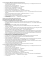
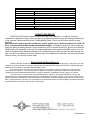
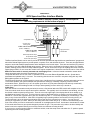
GPS-50-1 GPS Speed and Bus Interface Module IMPORTANT NOTE! When used to operate a cruise control, see the special mounting requirements on the bottom of page 4. www.dakotadigital.com [email protected] 605-332-6513 GPS-50-1 I/O I/O GROUND BATTERY ACC PWR SPEED 1 SPEED 2 CRUISE GPS INTERFACE setup/status switch Connect to main chassis ground +12V CONSTANT BATTERY POWER (fused 5 - 20 AMP max) +12V To gauge control box or another BIM KEY ON POWER (fused 5 - 20 AMP max) Standard speedometer output. AC speedometer output. Cruise control speed output. This Bus Interface Module can be used to provide an accurate speedometer signal with most manufacturers’ gauges and also with a Dakota Digital system to provide speed, compass, clock, and altimeter functions. There are two speedometer outputs to work with standard speedometers and a dedicated cruise control output. There are two interface (I/O) ports on the module for use with a Dakota Digital gauge system. Either one can be connected to the gauge system or to another module, allowing several units to be daisy chained together. Do not connect the I/O port to anything other than a Dakota Digital gauge or BIM. Do not mount the module in the engine compartment; it should be mounted in interior of the vehicle. Make sure the module is securely mounted and not hanging loose. It uses an internal acceleration sensor which cannot accurately track the vehicle acceleration if it is loose. The speed data does not use one of the 16 available bus ID’s like other Dakota Digital BIM units do. Speed data is transmitted and updated every 0.1 second. The remaining data is sent one at a time in sequence along with any other BIM modules present on the system. The GPS speed signal can be momentarily incorrect due to interference from overpasses, tunnels, and nearby structures. To avoid this problem, the system stabilizes the speedometer reading by constantly comparing it with an internal acceleration sensor. When the key is off, the system goes into a very low power standby mode and only occasionally wakes up to update GPS readings so that it is ready to start operating as soon as the key is turned on. Initial setup Once the module is mounted securely and wired, there are a few internal tasks the GPS module will complete on its own. First, the module needs time to acquire and track the satellites. This typically won’t work inside a steel building, so have the vehicle outside to speed up the process. There is a dot in the upper right of the display that will be on steady or on and flashing any time the key is on. The dot in the top center of the display will be on steady once it has gotten a GPS satellite fix. The unit won’t operate until it gets a fix and this may take 1 – 15 minutes depending on various things. This delay is only for the initial GPS fix. After this it will typically begin operating within a few seconds of turning the key on. The second step is to let the internal acceleration sensor learn how it is mounted in the vehicle. You can mount it securely in any position you want. When you are sitting still it learns which way is up. In order to learn which way is the front of the vehicle you need to accelerate or decelerate on a straight stretch of road. Accelerate or decelerate for at least 2.5 seconds and make sure your speed changes by at least 10 mph. This procedure only needs to be done initially and doesn’t need to be repeated unless you move the module to a different mounting location. If you move it to a new mounting location or a different vehicle, enter the setup menu and select the option to speed up learning the new mounting position. 1 MAN #650398:A Dakota Digital display data usage The speed outputs can each be used in place of a separate transmission connection to the gauge control unit. The clock is based on the accurate GPS time and only the hours need to be set to match it to your time zone. The compass requires no setup or calibration for the vehicle and is accurate any time the vehicle is moving. The altimeter is calculated from the GPS position data to give your current elevation. Each of these can be individually turned on or off. The compass and altimeter may not display correctly unless the gauge control has the following firmware version or higher: VHX VX04.009 VFD3 SE46 VFD3X SE55 The compass, clock, and altimeter will be displayed in the message center. Using speed from the GPS-50-1 without a BIM-01-1 connected Make sure the BIM units are all connected to the gauge control box with the supplied 3.5mm data cables. Hold the SW1 switch from the gauge system control box while turning the key on. The message display should show SETUP. Release SW1. The message display should show SPEED. Press and hold SW1. The message display should show SENDER. Release SW1. Press and release SW1 until BUS is displayed. Press and release SW1 until DONE is displayed. Turn the key off. Next, press and hold the switch on the GPS-50-1 while turning the key on. The GPS-50-1 display should show the current software revision. Release the switch. The display should show “”. Press and hold the switch until “ ” is displayed. Release the switch. The display should show “SPD”. Press and hold the switch until “ ” is displayed. Release the switch. The display will show the current setting. Press and release the switch until “ON” is displayed. Press and hold the switch until “ ” is displayed. Turn the key off. Using speed from the GPS-50-1 with a BIM-01-1 connected Make sure the BIM units are all connected to the gauge control box with the supplied 3.5mm data cables. Hold the SW1 switch from the gauge system control box while turning the key on. The message display should show SETUP. Release SW1. The message display should show SPEED. Press and hold SW1. The message display should show SENDER. Release SW1. Press and release SW1 until NORMAL is displayed. Press and release SW1 until DONE is displayed. Turn the key off. Next, press and hold the switch on the GPS-50-1 while turning the key on. The GPS-50-1 display should show the current software revision. Release the switch. The display should show ”. Press and hold the switch until “ ” is displayed. Release the switch. The display should show “SPD”. Press and hold the switch until “ ” is displayed. Release the switch. The display will show the current setting. Press and release the switch until “OFF” is displayed. Press and hold the switch until “ ” is displayed. Turn the key off. Connect the GPS-50-1 SPEED 1 terminal to the gauge control box SPD SND terminal. 2 MAN #650398:A To set or change the GPS clock ID number and the time format: Hold the switch beside the GPS-50-1 terminal strip while turning the key on. The display will show the current revision code while this is held. Release the switch. The display will show “”. Press the switch and hold the switch until “ ” is displayed. Release the switch. The BIM display will show “”. Press and release the switch until “ ” is displayed. Press the switch and hold the switch until “ ” is displayed. Release the switch. The display will show the current ID for the GPS clock. Press and release the switch to change the setting from - or . will prevent the GPS clock from being displayed. Press and hold the switch to save the setting. The BIM display will show “” or “”. Release the switch. This is the current time format. Press and release the switch to change between 12 hour and 24 hour format. Press and hold the switch until “ ” is displayed to save the settings. Turn the key off. The time is set up through the gauge display system. Only VFD3/3X controls with a plastic case support adding BIM’s. For VFD3, VFD3X, and VHX systems follow these steps: Make sure the BIM units are all connected to the gauge control box with the supplied 3.5mm data cables. Hold the SW1 switch from the gauge system control box while turning the key on. The message display should show SETUP. Release SW1. Press and release SW1 until BIM is shown on the message display. Press and hold SW1. The message display should show SCAN followed by the number of BIM channels detected. Release SW1. If 0 is shown, check all connections and then press and hold SW1 with SCAN shown to retry reading the modules. Otherwise, if any other number is shown, press and release SW1 until SETUP is shown. Press and hold SW1 until the speed display shows “ – ” or the message changes. Release SW1. On the VFD3 systems the message display will show the label assigned to the channel and the speed display will show “C” followed by the channel ID number. On the VHX systems the message display will show “CH” followed by the channel ID number on one line and the label currently assigned on the second line. Press and release SW1 until the desired channel ID number is shown. Press and hold SW1. The message display will show “LABEL”. Release SW1. The message display will show “CLOCK”. The label cannot be changed. Press and hold SW1. The message display will show the current time. Release SW1. The message display will show the current time and the hours will flash. Press and release SW1 to change the hours. Press and hold SW1. On VFD3 systems the message display will now show “DONE” and the setup is finished. On VHX systems the message display will show “USE AS MAIN” with “Y” or “N” highlighted. With VHX systems release the switch and then press and release the switch to select whether the main system clock is read from the GPS-50 (Y) or the VHX internal clock (N). Press and hold SW1 until the display shows “DONE”. This can be repeated for additional channels, or the key can be turned off to exit setup. To set or change the Compass or Altimeter ID number: Hold the switch beside the GPS-50-1 terminal strip while turning the key on. The display will show the current revision code while this is held. Release the switch. The display will show “”. Press the switch and hold the switch until “ ” is displayed. Release the switch. The BIM display will show “”. Press and release the switch until “” is displayed for compass or “” for altimeter. Press the switch and hold the switch until “ ” is displayed. Release the switch. The display will show the current ID for that reading. Press and release the switch to change the setting from - or . will prevent it from being displayed. Press and hold the switch until “ ” is displayed to save the settings. Turn the key off. 3 MAN #650398:A Using an electric speedometer with the GPS-50-1. The speedometer signal input should be connected to either SPEED 1 or SPEED 2 depending on the speedometer requirements. If you are unsure of which to use, start with SPEED 1 and then switch to SPEED 2 if it doesn’t work. You can test the speedometer connection by entering the speedometer output setup described below. While you are at the speed cal selection, the output will provide a 60mph signal for testing. If you are going to be connecting a cruise control to the GPS-50-1, the CRUISE terminal provides an ECM style speed output signal. The output rate for this terminal is the same as for the SPEED terminals. It is not uncommon for the raw GPS speed data to vary by as much as 6 MPH when going under a large bridge or other structure. While this unit does use additional sensors to monitor and remove this, it may be possible to feel the cruise change slightly even though your speedometer will not show a change. Speedometer output setup. Hold the switch beside the GPS-50-1 terminal strip while turning the key on. The display will show the current revision code while this is held. Release the switch. The display will show “”. Press and release the switch until “” is displayed. Press the switch and hold the switch until “ ” is displayed. Release the switch. The display will show the current speed pulse setting, for 4000, for 8000, for 16000, for 54400, or for 128000. It will also drive the output with a 60mph (96 km/h) speed signal so you can verify the reading on your speedometer. Press and release the switch to change the setting. Press and hold the switch until “ ” is displayed to save the settings. Turn the key off. Setup Menu , -, -, -, ,,,, , xx xx xxxx set BIM ID’s enable or disable speed data on BIM set clock ID set compass ID set altimeter ID set or test the speedometer output calibration GPS/accelerometer override settings Lowest speed accelerometer override is allowed, default setting should be used GPS > accel, default setting should be used accel > GPS, default setting should be used speed averaging update, default setting should be used reset module orientation (relearn which direction is up and forward) signal to noise ratio readings for trouble shooting and diagnostics highest signal reading lowest signal reading average signal reading number of satellites being used exit setup Cruise control operation with the GPS-50-1 While a transmission or wheel based speed signal is ideal for operating a cruise control, the GPS-50-1 can be used when this is not available. Special care must be taken in selecting the mounting location for the GPS-50-1 so that it can get a clear view of the satellites. The difference in mounting locations is not noticeable for a speedometer, but can affect the precision operation of a cruise control system. Try to locate the GPS-50-1 as high as possible. It can be under a fiberglass or wood dash or in a headliner. Avoid having the unit surrounded by steel. The setup menu will aid in selecting an acceptable mounting location. This should be done in a clear, outside area and not inside a building. Hold the switch beside the GPS-50-1 terminal strip while turning the key on. The display will show the current revision code while this is held. Release the switch. Press and release the switch until “” is displayed. Press and hold the switch until “ - ” is displayed. Press and release the switch until “ ” is displayed. It should be tracking at least 6 satellites. If it is less than this wait a few minutes for it pick up additional satellites. Press and release the switch until “ ” is displayed. The maximum signal strength will be displayed in real time. You should try different locations to obtain a reading of or higher. 4 MAN #650398:A Troubleshooting quick tips: While the GPS-50-1 is operating, the dot in the upper left corner of the display will indicate the status. On steady indicates it is powered up but not receiving any BIM bus activity. Flashing indicates it is communicating on the BIM bus. A dot in the upper center indicates that it is receiving a valid GPS signal. A dot in the lower center indicates the accelerometer is actively correcting the speedometer reading. When the key is off the dot in the upper left corner will flash very slowly. If the switch on the GPS-50-1 is held, it will flash rapidly indicating that the key is off. To see the number of satellites being tracked, signal strength, speed, and heading on the GPS display, press and hold the switch with the key on. It will toggle between displaying the number of satellites tracked followed by a dash (), the signal strength followed by three dashes, current speed in km/h, and the heading in degrees. Troubleshooting guide. Problem Sensor does not show on gauge readout. GPS will not light up at all. Sensor does not show on gauge readout. GPS has a steady dot lit Speed always reads 0. GPS has a flashing dot in the upper left corner. Speed always reads 0. SPEED terminal is used for connection. Speed reading is incorrect. Speed seems to lag or is erratic. Cruise control will not engage. Cruise control will not hold a steady speed. BIM display shows “:” Possible cause BATTERY terminal is not powered. ACC PWR terminal is not powered. GND terminal does not have a good ground. Module is damaged. Interface cable is not connected. Interface cable is loose. On VHX systems, the BIM display for this channel is disabled. Another BIM is set with the same channel IDs. GPS data is out-dated. Solution Connect to a location that has power at all times. Connect to a location that has power with the key on. Connect to a different ground location. Return for service. (see instructions) Connect the supplied 3.5mm data cable between the BIM unit and the gauge control box. Make sure both ends of the cable are seated in securely. Follow instructions in VHX manual to enable the BIM display screen. Test module works when connected to control box alone. Change ID’s on one of the modules so each module uses unique IDs. If the constant power connection has been disconnected, it may take 5 – 15 minutes for it to get valid data from the satellites. GPS receiver cannot get a signal. If the car is inside a garage or other structure it may not be able to receive a signal from the satellites. Move the vehicle to an open area and retest. Broken or loose wire connection. Inspect and reconnect wires. Wire connected to the wrong output. Switch between the #1 and #2 output types and retest. Output calibration is incorrect. See “Speedometer output setup” in the manual. Speedometer output is set incorrectly. See “Speedometer output setup” in the manual. Speedometer is not accurate. Consult your speedometer manual to determine the calibration steps. Module is not mounted securely and is Mount the module securely using screws or hook and loop tape. sliding around while driving. The internal acceleration sensor needs Accelerate or decelerate in a straight line to allow the system to calibrate to learn which direction is forward. itself. Speed output rate does not match. Change either the GPS-50-1 or cruise control speed pulse rate so they match each other. Loose wire connection. Inspect wiring connections. Cruise speed type is set incorrectly. Make sure the cruise control is set for an ECM type signal. Speed output rate does not match. Change either the GPS-50-1 or cruise control speed pulse rate so they match each other. Gain control on cruise incorrect. See cruise control manual to adjust gain or sensitivity. GPS mounting location causing Move the GPS-50-1 to a new location to minimize signal reflections. degraded signal. Be sure to perform a reset after moving the unit. Speed signal wire is picking up noise. Isolate the speed signal wire from tachometer or motor wires. Data cable is damaged. Inspect and replace 3.5mm data cable. Another module on the bus is damaged Inspect other modules on the data bus. or connected improperly. 5 MAN #650398:A Battery Power Accessory Power Update Rate SPEED 1 SPEED 2 CRUISE Accessory On Accessory Off GPS-50-1 Specifications SUPPLY VOLTAGE 6 to 22 V 6 to 22 V SPEED OUTPUTS 10 Hz Ground switching (1.4 A max) +/- 6V typical at 13V power Ground switching (0.3 A max) CURRENT DRAW ≈ 39 mA ≈ 4 mA SERVICE AND REPAIR DAKOTA DIGITAL offers complete service and repair of its product line. In addition, technical consultation is available to help you work through any questions or problems you may be having installing one of our products. Please read through the Troubleshooting Guide. There, you will find the solution to most problems. Should you ever need to send the unit back for repairs, please call our technical support line, (605) 3326513, to request a Return Merchandise Authorization number. Package the product in a good quality box along with plenty of packing material. Ship the product by UPS or insured Parcel Post. Be sure to include the RMA number on the package, and include a complete description of the problem with RMA number, your full name and address (street address preferred), and a telephone number where you can be reached during the day. Any returns for warranty work must include a copy of the dated sales receipt from your place of purchase. Send no money. We will bill you after repair. Dakota Digital 24 Month Warranty DAKOTA DIGITAL warrants to the ORIGINAL PURCHASER of this product that should it, under normal use and condition, be proven defective in material or workmanship within 24 MONTHS FROM THE DATE OF PURCHASE, such defect(s) will be repaired or replaced at Dakota Digital’s option. This warranty does not cover nor extend to damage to the vehicle’s systems, and does not cover removal or reinstallation of the product. This Warranty does not apply to any product or part thereof which in the opinion of the Company has been damaged through alteration, improper installation, mishandling, misuse, neglect, or accident. This Warranty is in lieu of all other expressed warranties or liabilities. Any implied warranties, including any implied warranty of merchantability, shall be limited to the duration of this written warranty. Any action for breach of any warranty hereunder, including any implied warranty of merchantability, must be brought within a period of 24 months from date of original purchase. No person or representative is authorized to assume, for Dakota Digital, any liability other than expressed herein in connection with the sale of this product. 6 MAN #650398:A