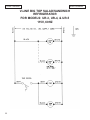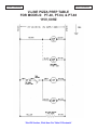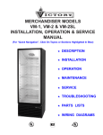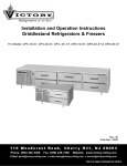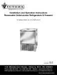
1
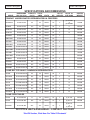
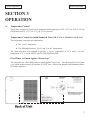
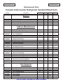
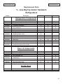
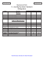
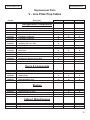
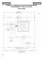
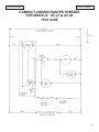
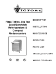
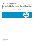
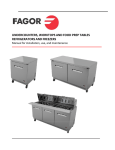
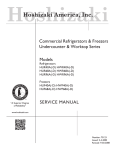
Pizza Tables, Big Top Salad/Sandwich
Refrigerators & Compact Undercounters
(For “Quick Navigation”, Click On Topics or Sections Highlighted In Blue)
★
DESCRIPTION
★
INSTALLATION
★
OPERATION
★
MAINTENANCE
★
TROUBLESHOOTING
★
PARTS LISTS
★
WIRING DIAGRAMS
Warranty
(Continental USA Only)
The Seller warrants to the original purchaser, equipment manufactured by Seller to be free from defects in material and
workmanship for which it is responsible. The Seller's obligation under this warranty shall be limited to replacing or
repairing at Seller's option, without charge, F.O.B. Sellers factory, any part found to be defective and any labor and
material expense incurred by Seller in repairing or replacing such part, such warranty to be limited to a period of one
year from date of purchase or thirteen months from date of shipment from Seller's factory, whichever is earlier, provided
terms of payment have been fully met. All labor shall be performed during regular working hours. Overtime premium
charges will be at Buyer's expense.
Proof of purchase must be supplied to Seller to validate warranty. This warranty is valid only if equipment is properly
installed, started-up and inspected by the dealer or authorized Victory Service agent.
Removal or alteration of the serial/data plate from any equipment shall be deemed to release Seller from all warranty
obligations or any other obligations, expressed or implied.
This warranty does not cover Thermostat or Defrost Timer calibration and/or adjustment, freight damage, normal
maintenance items outlined in Owner's Manual, adjustment of door mechanisms or replacement of light bulbs, fuses
or batteries.
Any repairs or replacement of defective parts shall be performed by Seller's authorized service personnel. Seller shall
not be responsible for any costs incurred if the work is performed by other than Seller's authorized service personnel.
Reimbursement claims for part(s) or labor service costs must be made in writing. Model, cabinet serial numbers and
installation location must be shown on the claim. A receipted bill from the servicing agency must accompany the claim,
together with full details of the service problems, diagnosis and work performed. Victory reserves sole discretion
whether further documentation on a claim is to be submitted.
Seller shall not be liable for consequential damages of any kind which occur during the course of installation of
equipment, or which result from the use or misuse by Buyer, its employees or others of the equipment supplied
hereunder, and Buyer's sole and exclusive remedy against Seller for any breach of the foregoing warranty or otherwise
shall be for the repair or replacement of the equipment or parts thereof affected by such breach.
The foregoing warranty shall be valid and binding upon Seller if and only if Buyer loads, operates and maintains the
equipment supplied hereunder in accordance with the instruction manual provided to Buyer. Seller does not guarantee
the process of manufacture by Buyer or the quality of product to be produced by the equipment supplied hereunder
and Seller shall not be liable for any prospective or lost product or profits of Buyer.
THE FOREGOING WARRANTY IS EXCLUSIVE AND IN LIEU OF ALL OTHER EXPRESS AND IMPLIED
WARRANTIES WHATSOEVER. SPECIFICALLY THERE ARE NO IMPLIED WARRANTIES OF MERCHANTABILITY
OR OF FITNESS FOR A PARTICULAR PURPOSE.
The foregoing shall be Seller's sole and exclusive obligation and Buyer's sole and exclusive remedy for any action,
whether in breach of contract or negligence. In no event shall Seller be liable for a sum in excess of the purchase price
of the item.
You may register online at www.victory-refrig.com, fax this completed page to (856) 428-7299, or copy and mail form below to Victory.
*NOTE: The following mail-in form or online registration must be filled out and forwarded to Victory by the installer or customer within 10 days
after start-up. Failure to do this will invalidate the warranties. Retain this information for your records.
110 WOODCREST ROAD
CHERRY HILL, NJ 08003-3648
TEL: (856) 428-4200 ● FAX: (856) 428-7299
WARRANTIES NOT VALID UNLESS REGISTERED AT
FACTORY WITHIN 10 DAYS AFTER START-UP DATE.
Cabinet Model No.______________________
Cabinet Serial No._________________
(Data plate information located inside cooler on
the upper left wall)
ORIGINAL DATE OF INSTALLATION __________________________________________________________________
INSTALLATION COMPANY NAME ____________________________________________________________________
STREET _______________________________ CITY _____________________ STATE ______ ZIP CODE___________
DISTRIBUTOR’S NAME_____________________________________________________________________________
STREET _______________________________ CITY _____________________ STATE ______ ZIP CODE___________
TABLE OF CONTENTS
Page
SECTION 1 - DESCRIPTION.........……………………………………………………..1
A. Specifications & Dimension........................…………………………………………………..... 2
SECTION 2 - INSTALLATION........... …………………………………………………. 3
A. Receiving shipment..........................…………………………………………………………….3
B. Removing plastic cover............……………………………………………………….................3
C. Locating your new storage refrigerator/freezer............................……………………………….3-4
D. Installing legs............................…………………………………………………………………4
E. Removal of drawer assembly............................………………………………………………… 4
F. Electric supply............................…………………………………………………………………5
G. Installation check list................................……………………………………………………… 5
H. Location of serial number/data plate........................…………………………………………… 6
I. Warranty cards...........….................………………………………………………………………6
SECTION 3 - OPERATION......... ………………………………………………………. 7
A. Temperature control..................................……………………………………………………… 7
B. Thermometer operation.............................………………………………………………………8
C. Important operating facts..........................……………………………………………………… 8
D. Food Pan Area..........................................……………………………………………………… 8
SECTION 4 - MAINTENANCE..........…………………………………………………...9
A. Cleaning - Proper detergent use.........................………………………………………………...9
B. Initial cleaning of cabinet.............................…………………………………………………….9
C. Periodic cleaning..............................…………………………………………………………….10-11
D. Lubrication..............................…………………………………………………………………..11
SECTION 5 - TROUBLESHOOTING.....………………………………………………. 13-15
SECTION 6 - PARTS LIST...……………………………………………………………..17
A. Compact Undercounter Refrigerator & Freezer............……………………………………........18-21
B. Compact Undercounter Refrigerator Salad/Sandwich Unit...........………………………….......22-24
C. Big Top Salad/Sandwich Refrigerator................………………………………………………...25-26
D. Pizza Prep Tables...................…………………………………………………………………... 27-28
SECTION 7 - ELECTRIC SCHEMATIC ………………………………………………29
A. Compact Undercounter Refrigerator .............………………………………………………….. 30
B. Compact Undercounter Freezer..................…………………………………………………….. 31
C. Big Top Salad/Sandwich Refrigerator ............…………………………………………………. 32
D. Pizza Prep Table ...............………………………………………………………………………33
iv
Section 1-Description
Section 1-Description
SECTION 1
DESCRIPTION
Compact Undercounter Refrigerators, Freezers, Salad/Sandwich Refrigerators and
Pizza Tables.
° Compact Undercounters - Available in 27” and 48” widths. The stainless steel top can be
flat or with a backsplash. Drawer models (27” units only) have two stainless steel drawer
fronts with heavy duty stainless steel slides and ball bearings.
° Compact Salad/Sandwich Refrigerators - Available in 27” and 48” widths with stainless
steel telescoping lid and utility shelf. The 27” unit has openings in the top for eight (8) pans.
The 48” units have openings in the top for eight (8), ten (10), or twelve (12) pans.
*Note: These units do not consist of a backsplash
° V-Line Big Top Salad/Sandwich Refrigerators - Available in 30-3/4”, 46-3/4” or 61-1/4”
widths with stainless steel telescoping lids and utility shelf. The 30-3/4” units have openings
in the top for twelve (12) pans. The 46-3/4” units have openings in the top for twelve (12)
or eighteen (18) pans. The 61-1/4” units have openings in the top for twelve (12), sixteen
(16), eighteen (18), or twenty-four (24) pans.
° V-Line Pizza Tables - Available in 40-1/4”, 64-1/4” and 88-1/4” widths. Pizza tables are
designed with a cold wall pan rail system and forced air cabinet storage. Each cold wall rail
accommodates standard serving pans.
1
Section 1-Description
Section 1-Description
SPECIFICATIONS AND DIMENSIONS
MODEL
DIMENSIONS
W X D X H (in)
CAPACITY
(Cu Ft)
TOTAL
AMPS
VOLTS
H.P.
NO. OF
SHELVES
NO.OF 1/6
SIZE PANS
CRATED
WEIGHT
COMPACT UNDERCOUNTER REFRIGERATORS & FREEZERS
UR-27-SALA
27 X 30 1/2 X 42
6.5
5.6
115-60-1
1/5
2
(6) 1/6 PANS
&
(2) 1/9 PANS
175 LBS
UR-48-8A
48 X 30 1/2 X 42
11.5
6.5
115-60-1
1/5
4
8
250 LBS
UR-48-10A
48 X 30 1/2 X 42
11.5
6.5
115-60-1
1/5
4
10
250 LBS
UR-48-12A
48 X 30 1/2 X 42
11.5
6.5
115-60-1
1/5
4
12
250 LBS
UR-27-SST
27 X 30 1/2 X 36
7.0
5.6
115-60-1
1/5
2
-
155 LBS
URD-27-SST
27 X 30 1/2 X 36
7.0
6.0
115-60-1
1/5
-
-
195 LBS
UF-27-SST
27 X 30 1/2 X 36
7.0
6.7
115-60-1
1/3
2
-
160 LBS
UFD-27-SST
27 X 30 1/2 X 36
7.0
7.1
115-60-1
1/3
-
-
200 LBS
UR-27-SBS
27 X 30 1/2 X 40 1/2
7.0
5.6
115-60-1
1/5
2
-
157 LBS
URD-27-SBS
27 X 30 1/2 X 40 1/2
7.0
6.0
115-60-1
1/5
-
-
197 LBS
UF-27-SBS
27 X 30 1/2 X 40 1/2
7.0
6.7
115-60-1
1/3
2
-
165 LBS
UFD-27-SBS
27 X 30 1/2 X 40 1/2
7.0
7.1
115-60-1
1/3
-
-
205 LBS
UR-48-SST
48 X 30 1/2 X 36
12.5
6.0
115-60-1
1/5
4
-
218 LBS
UF-48-SST
48 X 30 1/2 X 36
12.5
7.1
115-60-1
1/3
4
-
225 LBS
UR-48-SBS
48 X 30 1/2 X 40 1/2
12.5
6.0
115-60-1
1/5
4
-
220 LBS
UF-48-SBS
48 X 30 1/2 X 40 1/2
12.5
7.1
115-60-1
1/3
4
-
227 LBS
V-LINE BIG TOP SALAD / SANDWICH REFRIGERATORS
UR-3-BT
30 3/4 X 34 X 45 3/4
8.0
4.9
115-60-1
1/5
2
12
225 LBS
UR-4-12-BT
46 3/4 X 34 X 45 3/4
10.0
7.0
115-60-1
1/4
4
12
240 LBS
UR-4-18-BT
46 3/4 X 34 X 45 3/4
10.0
7.0
115-60-1
1/4
4
18
250 LBS
UR-5-12
61 1/4 X 28 1/2 X 42 7/8
15.0
7.0
115-60-1
1/4
4
12
300 LBS
UR-5-16
61 1/4 X 28 1/2 X 42 7/8
15.0
7.0
115-60-1
1/4
4
16
305 LBS
UR-5-18-BT
61 1/4 X 34 X 45 3/4
15.0
7.0
115-60-1
1/4
4
18
350 LBS
UR-5-24-BT
61 1/4 X 34 X 45 3/4
15.0
7.0
115-60-1
1/4
4
24
355 LBS
V-LINE PIZZA TABLES
PT-40-S
40 1/4 X 34 X 45
7.7
6.8
115-60-1
1/4
2
(1) 12 X 35
400 LBS
PT-64-S
64 1/4 X 34 X45
16.9
7.5
115-60-1
1/3
4
(2) 12 X 27
490 LBS
PT-88-S 88
88 1/4 X 34 X45
26.2
10.0
115-60-1
1/2
6
(2) 12 X 27
&
(1) 12 X 20
525 LBS
50 CYCLE UNITS AVAILABLE - CONTACT FACTORY
“End Of Section, Click Here For Table Of Contents”
Section 2-Installation
Section 2-Installation
SECTION 2
INSTALLATION
A.
Receiving Shipment
Upon arrival, examine the exterior of the carton for any signs of rough handling. It is advisable that the
shipping carton be partially removed in order to examine the cabinet for any possible concealed damages
which might have occurred during shipment.
If no damages are evident, replace the shipping carton to protect the cabinet during local delivery. If the
cabinet is damaged, it should be noted on the delivery slip or Bill of Lading and signed to that effect. A
claim must be filed immediately against the carrier indicating extent and estimated cost of damage
incurred.
B.
Removing Protective Plastic Covering
WARNING
DO NOT, Under Any Circumstances
Lay Your New Equipment Down on Either
The Back, Front or Sides.
Remove the plastic covering by starting from one edge or corner carefully peeling the plastic from the
metal surfaces.
CAUTION:
Do not use scrapers or putty knives
to remove plastic covering.
C.
Locating your New Storage Freezer, Refrigerator
The following conditions should be considered when selecting a location for your refrigerator or
freezer!!!!
1. Floor Load - The floor on which the refrigerator will rest must be free of vibration and suitably strong
enough to support the combined weights of the refrigerator plus the maximum product load weight, it is
generally conceded that a safe figure is 35 pounds for each net cubic foot of storage space. For example,
a 10 cubic foot refrigerator could possibly hold approximately 350 pounds of products. (10 x 35 = 350)
2. Clearance - Do not remove the spacer from the rear of the compact undercounter. This guarantees
sufficient air circulation to the condensing unit. Pizza tables and Big Top refrigerators require a
minimum clearance of 3” between the back of the cabinet and the wall.
3
Section 2-Installation
C.
Section 2-Installation
Locating your New Storage Freezer, Refrigerator (continued)
3. Ventilation - The air cooled, self-contained refrigerator or freezer demands a sufficient amount of
cool clean air. Avoid placing the refrigerator or freezer near heat generating equipment, such as
ovens, ranges, heaters, fryers, steam kettles, etc., and out of direct sunlight. Avoid locating the selfcontained refrigerator or freezer in an unheated room or where the room temperature drops below
55°F.
4. Ambient Temperature - Salad/Sandwich refrigerator and pizza tables are approved for operation
under NSF-7 (+41°F) in a maximum ambient of +86°F.
D.
Installing Legs or Casters
Correct installation is very important to proper operation. This model must be - level when it is installed.
If cabinet is not level….
1. Doors may not seal properly.
2. Defrost water may overflow coil drain pan.
3. An excessive amount of ice may accumulate in coil drain pan of freezer models.
This model is supplied with adjustable type legs for leveling purposes. Legs are packaged and taped with
the cabinet for shipment. The legs must be secured to the leg braces on the underside of the cabinet. The
legs should be installed immediately after shipping skid has been removed.
Tip the model in one direction, block it from falling by using several pieces of 2 x 4 lumber or other
suitable material. Install legs securely while the model is in that position. Repeat this procedure to install
the remaining two legs.
Note: The above information pertains to “Casters” also.
E.
Removal of Drawer Assembly
1. Remove drawers from cabinet by pulling the drawer forward and lifting rollers out of notched front
end of slide.
2. Push slide back so that slide support rollers clear retaining strap. Lift out left hand and right hand
slides.
3. Lift front end of slide support channels to disengage rivets from keyhole slots in front of mounting
bracket. Pull forward slightly to disengage rear rivets from keyholes in rear bracket. Lift out side
support channel.
4. Remove screws holding front brackets on both sides of tank.
5. Rear brackets may be taken out if necessary by removing thumb screws holding them to the sides of
the tank.
4
Section 2-Installation
F.
Section 2-Installation
Electric Supply
The wiring must be done by a qualified electrician in accordance with local electrical codes. A separate
ground wire must be supplied for all installations.
A properly wired refrigerator or freezer will assure proper operation. Please consult the “Data” plate
attached to the compressor for the correct electrical requirements. Supply voltage requirements are on
the cabinet serial plate.
It is recommended that a direct, properly fused line of the proper size wire be installed from the main
supply to your refrigerator or freezer. It is most important that a voltage reading be made at the
compressor motor electrical connections, or as close to the compressor motor as possible at start-up and
while the refrigerator or freezer is in operation, to insure that the correct voltage required by the
compressor is being supplied.
Low or high voltage can detrimentally affect the refrigeration unit and thereby void its warranty.
G.
Installation Check List
After the cabinet has been installed, leveled and cleaned as described in the preceding paragraphs, refer
to the following check list prior to start-up.
°
Full voltage of the correct type, on a line not affected by the operation of other electrical
appliances, must be available at the condensing unit junction box during operation. Condensing
units are designed to operate with a voltage fluctuation of plus or minus 10% of the voltage
indicated on the cabinet electrical data plate. Burnout of a condensing unit due to exceeding the
high or low voltage limits will void the factory warranty.
°
Check all refrigeration lines to make sure they are not severely dented, kinked or rubbing.
°
Check condenser fan for freedom to rotate without striking any stationary members.
°
Cabinet must be properly leveled.
5
Section 2-Installation
H.
Section 2-Installation
Location of Serial Number/Data Plate
The serial data plate is mounted on the upper left interior tank wall inside the cabinet.
Note: When ordering replacement parts, you must include the complete cabinet model and serial
numbers!
I.
Warranty Cards
Locate the warranty cards at the rear of this manual. Fill out all three cards (“Factory Record Card”,
“Distributor’s Record Card” and “Customer’s Record Card”) and mail the Factory and Distributor’s cards
as directed. The customer’s card must be retained by the customer.
“End Of Section, Click Here For Table Of Contents”
Section 3-Operation
Section 3-Operation
SECTION 3
OPERATION
A.
Temperature Control
Temperature controls are factory set to maintain a food temperature of 38°F (3.3°C) to 40°F (4.4°C) for
refrigerators and 0°F (-17°C) to -5°F (-20.5°C) for freezers.
Temperature Control for Salad/Sandwich Units (UR-27-SALA; UR-48-8A, 10A & 12A)
The temperature control has two adjustments:
a. The “Cut in” temperature
b. The differential between “Cut in” and “Cut out” temperatures
The salad units have been adjusted to provide a “Cut in” temperature of 39° F and a “Cut out”
temperature of 32° F for the INLET AIR TO THE EVAPORATOR.
Fixed Timer to Guard Against “Freeze Ups”
The salad units use a fixed defrost timer to guard against “Freeze Ups”. Also the timer has a six (6) hour
cycle which includes twenty (20) minutes of “OFF” time. Observe the diagram and information below
for further assistance.
7
Section 3-Operation
B.
Section 3-Operation
Thermometer Operation
The thermometer is located so that opening the door for even a brief period of time may cause the
thermometer to indicate danger. The recover rate of the length of time required for the thermometer to
indicate safe temperature is also rapid (usually a few minutes).
C.
Important Operating Facts
Your new model is completely self-defrosting. Frost is automatically removed from concealed coil
finned surfaces at predetermined intervals. All defrost condensate water is directed to a vaporizer pan
and is disposed of automatically, no floor drain is required.
A fan motor circulates cold air throughout the fresh food and freezer storage compartments. This
provides more uniform temperatures and very rapid recovery to proper operating temperatures after door
opening, with its admission of warm room air.
The length of time required to remove the “heat” admitted due to prolonged or frequent door openings
or the “heat” from a product load is dependent upon several factors. One is the amount of heat introduced
into the cabinet due to duration and frequency of door openings; another is the temperature and size of
the load being refrigerated. For example, placing a hot load of dough in a refrigerator will definitely
cause the thermometer display to go into, and remain in, the danger zone for a prolonged period of time.
This is normal and must be expected. However, you should be concerned if the thermometer indicates
danger and the door(s) have NOT been opened or a warm product load has NOT been placed in the
refrigerator. This may indicate a malfunction.
D.
Food Pan Area
This is a “Food Holding” area only and is not approved for food storage. At the close of each work day,
the food pans should be moved to a storage refrigerator. The pan area should be cleaned and left with
empty pans and closed lid(s) . When loaded with +35°F cold product, the pans will maintain a
temperature of +41°F or less for up to four (4) hours with the lid(s) open, as required by NSF (National
Sanitation Foundation) in a +86°F ambient.
*Note: Food products must be 1/2” or more below the top of the pan(s). NSF protocol is for 4” deep
pans.
Continued use of this equipment will allow you to become familiar with its operation and functions.
“End Of Section, Click Here For Table Of Contents”
Section 4-Maintenance
Section 4-Maintenance
SECTION 4
MAINTENANCE
A.
Cleaning and Proper Detergent Use
Follow requirements of local health authorities.
1. Use a detergent-sanitizer or a mild detergent (neutral) or mildly alkaline (recommended for metal
surfaces) followed by a sanitizing rinse solution. These chemicals are necessary to kill or deactivate
the micro-organisms on the surface areas in contact with stored food. Choose these chemicals
carefully. Some are toxic and should only be used on non-food surfaces.
CAUTION:
DO NOT USE ABRASIVE CLEANING SOLVENTS!!!!
Never scour any part of your refrigerator. Scouring powders or chemicals may cause damage by
scratching or dulling the gleaming surface finish. Use alkaline, alkaline chlorinated or non-chloride
cleaners.
2. Avoid cleaners containing quaternary salts as they also can attack stainless steel and cause pitting and
rusting.
3. When using these products, it is important to follow label directions exactly to obtain the correct
cleaning action.
B.
Initial Cleaning of Cabinet
CAUTION:
DO NOT USE ABRASIVE CLEANING SOLVENTS!!!!
Prior to placing your new refrigerator into operation, it is advisable that the interior be washed thoroughly
with a mild detergent and water solution. Rinse with clear water and a sanitizing solution. Allow cabinet
to air dry.
9
Section 4-Maintenance
C.
Section 4-Maintenance
Periodic Cleaning
It is more convenient to clean your refrigerator or storage freezer when the product load is at its lowest
point.
1. Daily Exterior Surface Cleaning
Cleaning and sanitizing agents for stainless steel and aluminum exteriors should be used daily.
a. Dip sponge in cleaning solution, wipe down surfaces.
b. Polish with clean soft cloth. Wipe in direction of grain. Once a week a film cutting agent may
be used for metal finishes to maintain a shining surface.
2. Weekly Interior Accessory Cleaning
It is recommended a minimum of once a week to maintain good sanitary conditions and to eliminate
odors.
a. Disconnect power by switching circuit breaker “OFF”, or removing power cord from
receptacle.
b. Remove all food to protective temporary storage.
c. Open doors and allow warm room air to enter cabinet.
d. Remove all accessories (shelves, racks, etc.) from within the cabinet and scrub with a
detergent solution and a nylon bristled brush.
e. Rinse with clear water.
f. Soak in a final rinse of sanitizing solution for recommended period of time.
g. Remove and air dry.
3. Weekly Interior Surface Cleaning
a. When storage compartment(s) is sufficiently warm, remove all loose food particles.
b. Scrub all interior surfaces with warm detergent solution 100°F - 120°F (38°C - 39°C) and a
nylon bristled brush. Scrub the floor and ceiling surfaces of the interior walls, corners, inner
door surface, gaskets, and latches.
c. Rinse with warm clean water using a sponge.
d. Remove excess rinse water with sponge.
e. Rinse with clear water.
10
Section 4-Maintenance
Section 4-Maintenance
3. Weekly Interior Surface Cleaning (continued)
f. Allow to air dry.
g. Return accessories to unit.
h. Return power (electric) to unit.
i. Return food to cabinet when temperature indicator reaches safety zone.
4. Every Three Months, Condenser Maintenance
Cleaning is recommended at least once every three (3) months. However, once a month is
recommended when unit is located near cooking equipment which produces grease laden vapors,
i.e.: fryers, grills, steam kettles, etc.
a. Disconnect power by switching circuit breaker to “OFF” position or removing power cord
from receptacle.
b. Use a vacuum cleaner with proper brush attachments to clean the condenser, compressormotor and related parts.
c. In extreme cases of dust and grease build-up, the condenser fins may require blowing out with
compressed air.
Note: The air cooled condensing unit depends upon the amount of air passing through the condenser.
Grease, lint and dust accumulation reduces required air flow. The refrigerator will consume less current
and operate more efficiently if the condenser is kept clean.
WARNING:
Failure to keep condenser clean may cause
premature failure of motor/compressor
which will NOT be covered by warranty!
D.
Lubrication
Unless otherwise specified, all Victory refrigerators are equipped with oilless type motors. The
compressor motor is a sealed unit and is constantly being lubricated when in operation. The condenser
and the evaporator motors are equipped with “Life-time” oiled bearings. These bearings are oiled at the
factory and need never be oiled again.
“End Of Section, Click Here For Table Of Contents”
Section 4-Maintenance
Section 4-Maintenance
NOTES
Section 5-Troubleshooting
Section 5-Troubleshooting
SECTION 5
TROUBLESHOOTING
13
TROUBLESHOOTING & SERVICING REFRIGERATION SYSTEM
PROBLEM
1. Condensing unit fails to start - no
hum.
2. Condensing unit fails to start hums, but trips on overload
protector.
POSSIBLE CAUSE
1. Line disconnect switch open.
2. Fuse removed or blown.
3. Overload protector tripped.
4. Control stuck in open position.
5. Wiring improper or loose.
1. Close start or disconnect switch.
2. Replace fuse.
3. Determine reason and
correct/replace control.
4. Repair or replace control.
5. Check wiring against diagram.
1.
2.
3.
4.
1.
2.
3.
4.
Improperly wired.
Low voltage to unit.
Starting capacitor defective.
Relay failing to close.
5. Compressor motor has a winding
open or shorted.
6. Internal mechanical trouble in
compressor.
3. Condensing unit starts, but fails
to switch off of “start” winding.
1. Improperly wired.
2. Low voltage to unit.
3. Relay failing to open.
4. Run capacitor defective.
5. Excessively high discharge
pressure.
6. Compressor motor has a winding
open or shorted.
7. Internal mechanical trouble in
compressor.
4. Condensing unit starts and runs,
but short cycles on overload
protector.
1. Additional current passing through
overload protector.
2. Low voltage to unit (or
unbalanced if three phase.)
3. Overload protector defective.
4. Run capacitor defective.
5. Excessive discharge pressure.
6. Suction pressure too high.
7. Compressor too hot - return gas.
8. Compressor motor has a winding
shorted.
5. Condensing unit runs but short
cycles on...
1. Overload protector.
2. Thermostat.
3. High pressure cut-out due to:
a. Insufficient air or water supply.
b. Overcharge.
c. Air in system.
4. Low pressure cut-out due to:
a. Liquid line solenoid leaking.
b. Compressor valve leak.
c. Undercharge.
d. Restriction in expansion
device.
6. Condensing unit operates for
prolonged periods or
continuously.
14
REMEDY
1. Shortage of refrigerant.
2. Control contacts stuck or frozen
closed.
3. Excessive heat load placed into
cabinet.
4. Prolonged or too frequent door
openings.
5. Evaporator coil iced.
6. Restriction in refrigeration
system.
7. Dirty condenser.
8. Filter dirty.
Check wiring against diagram.
Determine reason and correct.
Determine reason and replace.
Determine reason and
correct/replace if necessary.
5. Replace compressor.
6. Replace compressor.
1. Check wiring against diagram.
2. Determine reason and correct.
3. Determine reason and
correct/replace if necessary.
4. Determine reason and replace.
5. Check discharge shut-off valve,
possible overcharge, or
insufficient cooling on condenser.
6. Replace compressor.
7. Replace compressor.
1. Check wiring diagram. Check for
added fan motors, pumps, etc. connected to wrong side of protector.
2. Determine reason and correct.
3. Check current , replace protector.
4. Determine reason and replace.
5. Check ventilation, restrictions in
cooling medium, restrictions in
refrigeration system.
6. For salad models, temperature
control differential set to closeincrease differential.
7. Check refrigerant charge (fix leak)
add if necessary.
8. Replace compressor.
1. See (4) above.
2. Differential set too close - widen.
3.
a. Check air or water supply to
condenser-correct.
b. Reduce refrigerant charge.
c. Purge.
4.
a. Replace.
b. Replace.
c. Fix leak, add refrigerant.
d. Replace device.
1. Fix leak, add charge.
2. Clean contacts or replace control.
3. Allow unit sufficient time for
removal of latent heat.
4. Plan or organize schedule to
correct condition.
5. Defrost.
6. Determine location and remove.
7. Clean condenser.
8. Clean or replace.
TROUBLESHOOTING & SERVICING REFRIGERATION SYSTEM
PROBLEM
POSSIBLE CAUSE
7. Start capacitor open or shorted
blown.
1. Relay contacts not opening
properly.
2. Prolonged operation on start cycle
due to:
a. Low voltage to unit.
b. Improper relay.
c. Starting load too high.
3. Excessive short cycling.
4. Improper capacitor.
8. Run capacitor open, shorted or
blown.
1. Improper capacitor.
2. Excessively high line voltage
(110% of rated-max.)
9. Relay defective or burned out.
1.
2.
3.
4.
Incorrect relay.
Incorrect mounting angle.
Line voltage too high or too low.
Excessive short cycling.
5. Relay being influenced by loose
vibrating mounting.
6. Incorrect run capacitor.
REMEDY
1. Clean contacts or replace relay if
necessary.
2.
a. Determine reason and correct.
b. Replace.
c. Correct by using pump down
arrangement if necessary.
3. Determine reason for short cycling
(see 5 above) and correct.
4. Determine correct size and
replace.
1. Determine correct size and
replace.
2. Determine reason and correct.
1.
2.
3.
4.
Check and replace.
Remount relay in correct position.
Determine reason and correct.
Determine reason (see 5 above)
and correct.
5. Remount rigidly.
6. Replace with proper capacitor.
10. Product zone temperature too
high.
1. Control setting too high.
2. Inadequate air circulation.
1. Reset control.
2. Rearrange product load to
improve air circulation.
11. Suction line frosted or sweating.
1. Overcharge of refrigerant.
2. Evaporator fan not running.
3. If remote model, expansion valve
stuck open.
4. If remote model expansion valve
is passing excess refrigerant or is
oversized.
1. Correct charge.
2. Determine reason and correct.
3. Clean valve of foreign particles.
Replace if necessary.
4. Readjust valve or replace with
smaller valve.
12. Liquid line frosted or sweating.
1. Restriction in dehydrator or
strainer.
2. Liquid shut-off (king valve)
partially closed.
1. Replace part.
1.
2.
3.
4.
1.
2.
3.
4.
13. Noisy condensing unit.
Loose parts or mounting.
Tubing rattle.
Bent fan blade causing vibration.
Fan motor bearings worn.
2. Open valve fully.
Find and tighten.
Reform to be free of contact.
Replace blade.
Replace motor.
“End Of Section, Click Here For Table Of Contents”
Section 5-Troubleshooting
16
NOTES
Section 5-Troubleshooting
Section 6-Parts List
Section 6-Parts List
SECTION 6
PARTS LIST
Page
Compact Undercounter Refrigerators and Freezers…………………………………18-21
Compact Undercounter Refrigerator Salad/Sandwich Units………………………..22-24
V - Line Big Top Salad/Sandwich Refrigerators……………………………………25-26
V - Line Pizza Prep Tables....………………………………………………………..27-28
17
Section 6-Parts List
Section 6-Parts List
Replacement Parts
Compact Undercounter Refrigerators & Freezers
Part No.
Description
UR-27
UR-48
UF-27
UF-48
X
X
X
X
X
X
X
X
Refrigeration Components
50629701
50180701
50785501
Coil, Evaporator (63F16)
Accumulator, 1/2” Ports Suction Line
Drier, Filter
X
X
X
X
X
X
50783501
50788101
Compressor 1/5 h.p. R-134A
Compressor 1/3 h.p. R-404A
X
X
10708801
10719201
Heat Exchanger AssemblyX
Heat Exchanger Assembly
X
50785601
50639801
50602602
10708503
10708504
04433101
Coil, Condenser (63C12)
Fan Motor, Condenser
Fan Blade, Condenser
Fan & Coil Assembly, Condenser
Fan & Coil Assembly, Condenser
Bracket, Condenser Fan
10708701
10719001
X
X
X
X
X
X
X
X
X
X
X
X
X
X
X
X
X
X
X
X
X
X
Coil, Evaporator Assembly, R-134A
Coil, Evaporator Assembly, R-404A
X
X
X
X
44131501
44131502
10708401
10708404
50639801
50602603
04119901
50625701
Evaporator Fan Panel Assembly
Evaporator Fan Panel Assembly
Evaporator Fan Assembly
Evaporator Fan Assembly
Fan Motor, Evaporator
Fan Blade, Evaporator
Bracket, Evaporator Fan
Guard, Fan
X
X
X
X
X
X
X
X
X
X
X
X
50198901
50199101
50654101
Capillary Tube 10’ x .036 R-404A
Capillary Tube 10’ x .049 R-134A
Condensate Drain Pan
X
X
X
X
50616101
50616201
50569502
Temperature Control, Freezer
Temperature Control, Refrigerator
Thermometer, Hanging Stem
X
X
X
X
X
X
X
X
X
X
X
X
X
X
X
X
X
X
X
X
X
X
X
X
X
X
X
X
X
X
X
X
X
Electrical Components
50631501
50518901
50636401
50632701
50657001
50636201
18
Heater, Evaporator Coil Defrost (115V, 200W)
Heater, Center Mullion
Timer, Defrost
Electric Harness (Power Cord & Plug Assembly)
Electric Harness (Power Cord & Plug Assembly)
Safety, Defrost Limit
X
X
X
Section 6-Parts List
Section 6-Parts List
Replacement Parts
Compact Undercounter Refrigerators & Freezers
Part No.
Description
UR-27
UR-48
UF-27
UF-48
Doors & Components
55113501
55113502
55113601
55113602
55114401
55114402
55114403
55114404
55113505
55113506
55115001
Door Assembly, RH
Door Assembly, LH
Door Assembly, RH
Door Assembly, LH
Door Assembly with
Door Assembly with
Door Assembly with
Door Assembly with
Door Assembly with
Door Assembly with
Latch Assembly
X
X
50630601
50630602
50635201
50635202
50635203
50635301
50635302
Gasket
Gasket
Gasket Retainer, Door Sides
Gasket Retainer, Top & Bottom
Gasket Retainer, Top & Bottom
Liner, Inner Door
Liner, Inner Door
X
X
X
X
Locks, RH
Locks, LH
Locks, RH
Locks, LH
Dial Thermometer, RH
Dial Thermometer, LH
X
X
X
X
X
X
X
X
X
X
X
X
X
X
X
X
X
X
X
X
X
X
X
X
X
X
X
X
X
X
X
X
Drawers & Components (URD 27’s)
55113703
55113704
Drawer Assembly, Lower
Drawer Assembly, Upper
X
X
50630603
50635202
50635201
Gasket, Drawer (Product)
Gasket, Retainer, Drawer, Top & Bottom
Gasket, Retainer, Drawer, Side
X
X
X
50714801
50635303
55113901
Pan, Drawer (12 x 20 x 6)
Pan, Drawer
Front Assembly, Drawer
X
X
X
55114701
55114702
05109902
Track, Drawer Slide, Right
Track, Drawer Slide, Left
Channel, Slide Support
X
X
X
55114303
55114304
50543803
Slide Support Assembly with Rollers, Left
Slide Support Assembly with Rollers, Right
Roller Bearing, Slide Support
X
X
X
09145901
09145902
09146001
09146002
Bracket,
Bracket,
Bracket,
Bracket,
X
X
X
X
Drawer
Drawer
Drawer
Drawer
Slide
Slide
Slide
Slide
Lower Front, Left
Lower Front, Right
Upper Front, Left
Upper Front, Right
19
Section 6-Parts List
Section 6-Parts List
Replacement Parts
Compact Undercounter Refrigerators & Freezers
Part No.
Description
UR-27
UR-48
UF-27
UF-48
Drawers & Components cont’d
09146101
09146102
09146201
09146202
Bracket,
Bracket,
Bracket,
Bracket,
Drawer
Drawer
Drawer
Drawer
Slide
Slide
Slide
Slide
Lower Rear, Left
Lower Rear, Right
Upper Rear, Left
Upper Rear, Right
X
X
X
X
Hardware
99147201
99147301
Hinge Kit Assembly, Upper
Hinge Kit Assembly, Lower
X
X
X
X
X
X
X
X
50621901
50641801
50651102
50586002
50671801
Bushing, Nylon, Hinge Bracket
Spacer, Hinge with Screws
Handle, Door
Leg, Stainless Steel
Leg, Black
X
X
X
X
X
X
X
X
X
X
X
X
X
X
X
X
X
X
X
X
50096002
50648301
50648302
50642201
50648305
50648306
50703101
11115101
11115102
10714101
10714102
Caster, Swivel 5” with Brake
Caster, Swivel 3” with Brake (Front)
Caster, Swivel 3” without Brake (Rear)
Caster, 1 1/4” Mighty Mite
Caster, 2 1/2” with Brake (Front)
Caster, 2 1/2” without Brake (Rear)
Heli Coil Insert (used with part number 50642201)
Leg Brace, Front
Leg Brace, Front
Leg Brace, Rear
Leg Brace, Rear
X
X
X
X
X
X
X
X
X
X
X
X
X
X
X
X
X
X
X
X
X
X
X
X
X
X
X
X
X
X
X
X
X
X
X
X
Shelves
50631602
50631701
50022501
33110201
33110301
Shelf, Wire Type
Shelf, Wire Type
Clip, Shelf
Support, Shelf Front
Support, Shelf Rear
X
X
X
X
X
X
X
X
X
X
Cabinet, Miscellaneous
50736401
50736501
50736502
09144801
09144901
20
Victory Logo, Plastic
Nameplate, “Victory” Refrigerator
Nameplate, “Victory” Freezer
Scrap Receptacle, Front
Scrap Receptacle, Rear
X
X
X
X
X
X
X
X
X
X
X
X
X
X
X
X
Section 6-Parts List
Section 6-Parts List
Replacement Parts
Compact Undercounter Refrigerators & Freezers
Part No.
Description
UR-27
UR-48
UF-27
UF-48
X
X
X
X
X
X
X
X
X
X
Cabinet, Miscellaneous cont’d
06116007
06116008
06116009
Back Panel, Galvanized (Top)
Back Panel, Galvanized (Bottom)
Back Panel, Galvanized (Left)
“End Of Section, Click Here For Table Of Contents”
Section 6-Parts List
Section 6-Parts List
Replacement Parts
Compact Undercounter Refrigerator Sandwich/Salad Units
Part No.
Description
UR-27-SALA UR-48-8A UR-48-10A UR-48-12A
Refrigeration Components
50629701
50180701
50785501
Coil, Evaporator (63F16)
Accumulator, 1/2” Ports Suction Line
Drier, Filter
X
X
X
X
X
X
X
X
X
X
X
X
50783501
Compressor 1/5 h.p. R-134A
X
X
X
X
10708801
Heat Exchanger AssemblyX
X
X
X
50785601
50639801
50602602
10708504
04433101
Coil, Condenser (63C12)
Fan Motor, Condenser
Fan Blade, Condenser
Fan Assembly, Condenser
Bracket, Condenser Fan
X
X
X
X
X
X
X
X
X
X
X
X
X
X
X
X
X
X
X
X
10708701
Coil, Evaporator Assembly R-134A
X
X
X
X
10792101
10792012
50639801
50602603
50830501
50830502
50625701
Evaporator Fan Assembly
Evaporator Fan Assembly
Fan Motor, Evaporator
Fan Blade, Evaporator
Fan Blade, Evaporator (White in Color)
Fan Blade, Evaporator (Gray in Color)
Guard, Fan
X
X
X
X
X
X
X
X
X
X
X
X
X
X
X
X
50199101
04454301
Capillary Tube 10’ x .049 R-134A
Condensate Drain Pan
X
X
X
X
X
X
X
X
50181402
50569502
Temperature Control, Refrigerator
Thermometer, Hanging Stem
X
X
X
X
X
X
X
X
X
X
X
X
X
X
X
X
X
X
X
X
X
X
X
X
X
Electrical Components
50518901
50744804
50833601
50836101
Heater, Center Mullion
Timer, Defrost (for 20 minute shutdown period)
Electric Harness (Power Cord & Plug Assembly)
Harness, Evaporator Fan Wire
*Note: The defrost timer shown on this parts list is not for an actual defrost cycle, but to assist in the twenty (20)
minute shutdown period every six (6) hours!!!!
22
Section 6-Parts List
Section 6-Parts List
Replacement Parts
Compact Undercounter Refrigerator Sandwich/Salad Units
Part No.
Description
UR-27-SALA UR-48-8A UR-48-10A UR-48-12A
Doors & Components
55113501
55113502
55113601
55113602
55114401
55114402
55114403
55114404
55113505
55113506
55115001
Door Assembly, RH
Door Assembly, LH
Door Assembly, RH
Door Assembly, LH
Door Assembly with
Door Assembly with
Door Assembly with
Door Assembly with
Door Assembly with
Door Assembly with
Latch Assembly
X
X
50630601
50630602
Gasket, Door
Gasket, Door
X
50635201
50635202
50635203
50635301
50635302
Gasket Retainer, Door Sides
Gasket Retainer, Top or Bottom
Gasket Retainer, Top or Bottom
Liner, Inner Door
Liner, Inner Door
X
X
Locks, RH
Locks, LH
Locks, RH
Locks, LH
Dial Thermometer, RH
Dial Thermometer, LH
X
X
X
X
X
X
X
X
X
X
X
X
X
X
X
X
X
X
X
X
X
X
X
X
X
X
X
X
X
X
Hardware
99147201
99147301
Hinge Kit Assembly, Upper
Hinge Kit Assembly, Lower
X
X
X
X
X
X
X
X
50621901
50641801
50651102
50586002
50671801
Bushing, Nylon, Hinge Bracket
Spacer, Hinge with Screws
Handle, Door
Leg, Stainless Steel
Leg, Black
X
X
X
X
X
X
X
X
X
X
X
X
X
X
X
X
X
X
X
X
50096002
50648301
50648302
50642201
50648305
50648306
50703101
11115101
11115102
10714101
10714102
Caster, Swivel 5” with Brake
Caster, Swivel 3” with Brake (Front)
Caster, Swivel 3” without Brake (Rear)
Caster, 1 1/4” Mighty Mite
Caster, 2 1/2” with Brake (Front)
Caster, 2 1/2” without Brake (Rear)
Heli Coil Insert (used with part number 50642201)
Leg Brace, Front
Leg Brace, Front
Leg Brace, Rear
Leg Brace, Rear
X
X
X
X
X
X
X
X
X
X
X
X
X
X
X
X
X
X
X
X
X
X
X
X
X
X
X
X
X
X
X
X
X
X
X
X
23
Section 6-Parts List
Section 6-Parts List
Replacement Parts
Compact Undercounter Refrigerator Sandwich/Salad Units
Part No.
Description
UR-27-SALA UR-48-8A UR-48-10A UR-48-12A
Shelves
50631602
50631701
50022501
33110201
33110301
Shelf, Wire Type
Shelf, Wire Type
Clip, Shelf
Support, Shelf Front
Support, Shelf Rear
X
X
X
X
X
X
X
X
X
X
X
X
X
Cabinet, Miscellaneous
50736401
50736501
“Victory” Logo, Plastic
Nameplate, “Victory” Refrigerator
X
X
X
X
X
X
X
X
50621101
50830401
50830403
Pin, Cutting Board
Cutting Board
Cutting Board
X
X
X
X
X
X
X
10803601
10803602
10803603
10803604
50632001
Hinged Lid Assembly
Hinged Lid Assembly
Hinged Lid Assembly
Hinged Lid Assembly
Handle, Lid with Screws
10804001
10804101
10804201
10804301
Assembly,
Assembly,
Assembly,
Assembly,
10803701
10803702
10803703
10803704
Back
Back
Back
Back
06116008
01378401
01379301
Back Panel, Galvanized (Bottom)
Back Panel, Galvanized (Left)
Back Panel, Galvanized (Top)
Case
Case
Case
Case
Top
Top
Top
Top
Cover Assembly
Cover Assembly
Cover Assembly
Cover Assembly
X
X
X
X
X
X
X
X
X
X
X
X
X
X
X
X
X
X
X
X
X
X
X
X
X
X
X
X
X
X
X
X
X
X
Pan Supports
09349701
09349702
50700601
50700602
Pan Support Bar
Pan Support Bar
Pan, Food Storage 1/6
Pan, Food Storage 1/9
01379201
01379001
01378801
01378601
Hood,
Hood,
Hood,
Hood,
Hinged
Hinged
Hinged
Hinged
X
X
X
X
X
X
X
“End Of Section, Click Here For Table Of Contents”
Section 6-Parts List
Section 6-Parts List
Replacement Parts
V - Line Big Top Salad / Sandwich
Refrigerators
Part No.
Description
UR-3
UR-4
UR-5
X
X
X
X
X
X
X
X
X
X
X
X
Refrigeration Components
50749901
50750001
50750101
50750201
Coil, Evaporator (2 x 5 x 14)
Coil, Evaporator (2 x 5 x 18)
Fan Motor, Evaporator
Fan Blade, Evaporator
X
50750301
50750401
50750501
50750601
Coil, Condenser
Fan Motor, Condenser
Fan Blade, Condenser
Fan Blade, Condenser
X
X
X
50750701
50750801
50750901
Capillary Tube 6’ x .031
Capillary Tube 10’ x .042
Capillary Tube 8 1/2’ x .042
X
50751001
50751101
50569502
Filter Drier
Temperature Control
Thermometer
X
X
X
50751201
50751301
Compressor Aspera 1/5 h.p. R-22
Compressor Aspera 1/4 h.p. R-22
X
X
X
X
X
X
X
X
X
X
X
X
X
Doors & Components
50751401
50751501
50751601
50751701
Door Assembly,
Door Assembly,
Door Assembly,
Door Assembly,
RH
LH
RH
LH
X
50751801
50751901
Gasket, Door
Gasket, Door
X
10685101
50752101
Hinge Assembly, Door
Handle, Door
X
X
X
X
X
X
X
X
X
X
X
X
Divider Bars
50834901
50819502
Divider Bar, Horizontal
Divider Bar, Vertical
X
X
25
Section 6-Parts List
Section 6-Parts List
Replacement Parts
V - Line Big Top Salad / Sandwich
Refrigerators
Part No.
Description
UR-3
UR-4
UR-5
Shelves
50752201
50752301
50752401
50768402
50762101
Shelf with Four (4) Clips
Shelf with Four (4) Clips
Shelf with Four (4) Clips
Clip, Shelf
Pilaster (w/ 2 accessory screws part no. 50257101)
X
X
X
X
X
X
X
X
X
X
X
X
X
Cabinet, Miscellaneous
50096002
50671801
50586002
50801901
Casters
Legs, Black
Legs, Stainless Steel
End Panel, Glue On
X
X
X
X
X
X
50752601
50752602
50752603
Cutting Board 12” x 30 1/2”
Cutting Board 12” x 46 1/2”
Cutting Board 12” x 61”
X
50632501
Pan, Food Storage 1/6 Size
X
X
X
50766001
50766101
50766201
50766301
Hood UR-3, UR-4, & UR-5-24
Hood UR-4-18 & UR-5-18
Roll Cover UR-3, UR-4-12 & UR-5-24
Roll Cover UR-3, UR-4-18 & UR-5-18
X
X
X
X
X
X
X
X
X
X
X
X
X
“End Of Section, Click Here For Table Of Contents”
Section 6-Parts List
Section 6-Parts List
Replacement Parts
V - Line Pizza Prep Tables
Part No.
Description
PT-40
PT-64
PT-88
Refrigeration Components
50752901
50750101
50750201
Coil, Evaporator (4 x 7 x 14 1/2)
Fan Motor, Evaporator
Fan Blade, Evaporator
X
X
X
X
X
X
X
X
X
50753001
50753101
50753201
Fan Motor, Condenser
Fan Blade, Condenser
Fan Blade, Condenser
X
X
X
X
X
X
50750801
50750901
50753301
Capillary Tube 10’ x .042
Capillary Tube 8 1/2’ x .042
Capillary Tube 9’ x .049
X
50751001
50751101
50569502
Filter Drier
Temperature Control
Thermometer
X
X
X
50753401
50753501
50753601
Compressor, Aspera 1/4 h.p. R-22
Compressor, Aspera 1/3 h.p. R-22
Compressor, Aspera or Tecumseh R-22
X
X
X
X
X
X
X
X
X
X
X
Doors & Components
50753701
50753801
Door Assembly, RH
Door Assembly, LH
X
X
X
X
X
50753901
Gasket, Door
X
X
X
10685101
50752101
Hinge Assembly, Door
Handle, Door
X
X
X
X
X
X
X
X
X
X
X
X
X
X
X
X
X
X
X
X
X
X
X
Shelves
50754001
50754101
50768402
50762101
Shelf with Four (4) Clips
Shelf with Four (4) Clips
Clip, Shelf
Pilaster (w/ 2 accessory screws part no. 50257101)
X
Cabinet, Miscellaneous
50096002
50671801
50586002
Casters
Leg, Black
Leg, Stainless Steel
27
Section 6-Parts List
Section 6-Parts List
Replacement Parts
V - Line Pizza Prep Tables
Part No.
Description
PT-40
PT-64
PT-88
Cabinet, Miscellaneous cont’d
50754201
50754202
50754203
Cutting Board 20” x 40”
Cutting Board 20” x 64”
Cutting Board 20” x 88”
X
50755501
50755502
Garnish Rack
Rubber Boot, Garnish Rack
X
X
50766401
50766501
50766601
50767001
50767201
50804201
50804301
Lid with Handle
Lid with Handle (Outer Section PT-88)
Lid with Handle (Center Section PT-88)
Lid Brackets & Pin Set
Lid Handle, 4”
Lid Bumper (Rubber)
Wall Bumper (Rubber)
X
50804701
50804801
Drawer Slide Kit
Roller (Drawer Model)
X
X
X
X
X
X
“End Of Section, Click Here For Table Of Contents”
X
X
X
X
X
X
X
X
X
X
X
X
X
X
X
X
X
Section 7-Schematics
Section 7-Schematics
SECTION 7
SCHEMATICS
29
Section 7-Schematics
Section 7-Schematics
COMPACT UNDERCOUNTER REFRIGERATOR
FOR MODELS: UR-27 & UR-48
115V, 60HZ
30
Section 7-Schematics
Section 7-Schematics
COMPACT UNDERCOUNTER FREEZER
FOR MODELS: UF-27 & UF-48
115V, 60HZ
31
Section 7-Schematics
Section 7-Schematics
V-LINE BIG TOP SALAD/SANDWICH
REFRIGERATOR
FOR MODELS: UR-3, UR-4, & UR-5
115V, 60HZ
32
Section 7-Schematics
Section 7-Schematics
V-LINE PIZZA PREP TABLE
FOR MODELS: PT-40, PT-64, & PT-88
115V, 60HZ
“End Of Section, Click Here For Table Of Contents”
VICTORY REFRIGERATION
110 Woodcrest Road
Cherry Hill, NJ 08003
Phone (856) 428-4200 Fax (856) 428-7299
Website: www.victory-refrig.com
E-Mail:[email protected]
[email protected]
or
[email protected]
Manual Part Number: 50647203
Rev: 03
Print Date: 11/5/01
Price: $15.00
Website: www.agafoodservice.com