1
OWNER'S
MANUAL
MODEL NO.
917.255520
..................................
::::iii,_
........
®
Caution:
Read and follow
all Safety Rules
and Instructions
Before Operating
This Equ=pment
oAssembly
o Operation
° Maintenance
° Service and Adjustment
° Repair Parts
,,ll
Sears,
Roebuck
,,N
i
,
i
and Co., Chicago,
...........................................
I,IMll,
II,l,lllllllll
IIllll
IL 60684 U.S.A.
SAFETY RULES
PLUG TO PREVENT ACCIDENTAL STARTING WHEN SETTING-UP, TRANSPORTING, ADJUSTING OR MAKING
CAUTION: ALWAYS DISCONNECT SPARK PLUGWtREAND PLACE WIRE WHERE IT CANNOT CONTACTSPARK
REPAIRS
&
INPORTANT
SAFETY STANDARDS REQUIRE O PERATOR PRESENCE CONTROLS TO MINIMIZE THE RISK OF INJURY, YOUR UNIT IS EQUIPPED WITH SU CH
CONTROLS,
DO NOT ATTEMPT TO DEFEAT THE FUNCTION OF THE OPERATOR PRESENCE CONTROLS UNDER ANY CIRCUMSTANCES,
•r
TRAINING:
•
•
•
,
•
•
Know the controls and how to stop quickly. Read this owner's
manual and instructions furnished with attachment&
Do not allow children to operate the machine. Do not allow
adults to operate it without proper instruction
Do not carry passengers Do not mow when children and
others are around
Do not attempt to operate your veh[cte or mower when not in
the driver's seat.
Always get on or off your vehicle from the operator's left hand
side.
The vehicle and attachments should be stopped and in_
spected for damage after striking a foreign object, and the
damage should be repaired before restarting and operating
the equipment
•
Never mow in wet or slippery grass, when traction is unsure,
or at a speed which could cause a skid.
•
Stay alert for holes in the terrain and other hidden hazards.
Keep away from drop-offs,
*
Do not drive too close to creeks, ditches, and public highways.
.
Exercise special care when mowing around fixed objects in
order to prevent the blades from striking them. Never detib.
erately run vehicle or mower into or over any foreign object&
•
Never shift gears until vehicle comes to a stop.
Never place hands or feet under the mower, in discharge
chute, or near any moving parts while vehicle or mower is
running Always keep clear of discharge chute,
•
Use care when pulling loads or using heavy equipmenL
Use only approved drawbar hitch points,
Limit loads to those you can safely control
Do not turn sharply, Use care when backing.
Use counterweight or wheel weights when suggested in
owner's manual
Watch out for traffic when crossing or near roadways.
•
When using any attachments, never direct discharge of
material toward bystanders nor allow anyone near the ve"-'_"f_icle while in operation
. E_xcept for adjustments, do not operate engine if air cleaner
Qr cover directly over carburetor air intake is removed.
Removal of such part could create a fire hazard.
iDo not change the engine governor settings or overspeed
the engine; severe damage or injury may result
When using the vehicle with mower, proceed as follows:
• \ Mow only in daylight or in good artificial light.
'k_
Shut the engine off when unclogging chute.
-\
Check the b]ade mounting beits for proper tightness at
PREPARATION:
Always wear substantial footwear. Do not wear loose fitting
clothing that could get caught in moving part&
Clear the work area of objects (wire, rocks, etc.) which might
be picked up and thrown
Disengage all attachment clutches before attempting to start
the engine.
Handle gasoline with care - it is highly flammable.
Use approved gasoline containers.
Never remove the fuel cap of the fuel tank or add gasoline
to a running or hot engine or an engine that has not been
allowed to cool for several minutes after running Never
fill tank indoors. Always clean up spiiled gasoline.
Open doors if the engine is run in the garage, exhaust
fumes are dangerous Do not run the engine indoors
Do not operate the mower without the entire grass catcher,
on mowers so equipped, or the deflector shield in place
OPERATION:
,
•
•
•
•
•
.
.
Keep your eyes and mind on your vehicle, mower, and the
area being CUL Do not let other interests distract you.
Disengage power to attachments and step the engine before
leaving the operator's position°
Disengage power to mower, stop the engine, and disconnect
spark plug wire(s) from spark plug(s) before cleaning, making
an adjustment, or repair. Be careful to avoid touching hot
muffler or engine component&
Disengage power to attachments when transporting or not in
use
Take all possible precautions when leaving the vehicle unattended Disengage the power take-off, lower the attachmerits, shift into neutral, set the parking brake, stop the
engine, and remove the key.
Do not stop or start suddenty when going uphill or downhitI
Mow up and down the face of slopes (not greater than 15"),
never across the face
Reduce speed on slopes and make turns gradually to prevent
tipping or loss of control Exercise extreme caution when
changing direction on slope&
While going up or down slopes, place gearshift controi _ever
in 1st gear position to negotiate the slope without stopping.
n_fr equent intervals.
Diseqgage power to mower before backing up., Do not mow
in reverse unless absolutely necessary and then only after
careful observation of the entire area behind the mower.
MAINTENANCE
•
•
•
•
•
AND STORAGE
Keep the vehicle and attachments in good operating condition, and keep safety devices in place and working
Keep all nuts, bolts, and screws tight to be sure the equipment is in safe working condition.
Never store the equipment with gasoline in the tank inside a
building where fumes may reach an open flame or spark
Allow the engine to cool before storing in any enclosure
To reduce fire hazard, keep the engine free of grass, leaves,
or excessive grease Do not clean product while engine is
running
Do not operate without a muffler, or tamper with exhaust
system. Damaged mufflers or spark arresters could create a
fire hazard. Inspect periodically and replace if necessary_
Under normal usage the grass catcher bag material is
sub ect to deterioration and wear. It Should be checked
frequent y for bag rep acemenL Replacement bags should
be checked
to ensure compliance
with the original
manufacturer's recommendations or specifications.
LOOK FOR THIS SYMBOL TO POINT OUT IMPORTANT SAFETY PRECAUTIONS.
tT MEANS - ATTENTIONHI
BECOME ALERTtl! YOUR SAFETY IS INVOLVED.
2
!
PRODUCT
CONGRATULATIONS
on your purchase of a Sears
Tractor. It has been designed, engineered and manufactured to give you the best possible dependability and
performance.
Should you experience any problem you cannot easily
remedy, please contact your nearest Sears Service
Center!Department.
We have competent, well-trained
technicians and the proper tools to service or repair this
unit.
Please read and retain this manual. The instructions will
enable you to assemble and maintain your unit properly.
Always observe the "SAFETY RULES".
MODEL
NUMBER
917255520
SPECIFICATIONS
HORSEPOWER:
125
GASOLINE
5 QUARTS
UNLEADED
CAPACITY:
OIL (3 0 PINTS):
SAE 30 (or 10W-30)
WINTER: SAE 5W-30
SPARK PLUG (GAP.030 IN ):
CHAMPION
STD361458
VALVE CLEARANCE:
INTAKE 005- 007 IN.
EXHAUST .009 - 011 IN.
GROUND SPEED:
FORWARD
1st 110 MPH
2nd 140 MPH
3rd 200 MPH
4th 3 O0 MPH
5th 4.20 MPH
6th 5OO MPH
REVERSE: 150 MPH
TIRE PRESSURE:
FRONT: 14 PSI
REAR: 10 PSi
CHARGING SYSTEM:
3 AMPS BATTERY
5 AMPS HEADLIGHTS
BLADE BOLT TORQUE:
30-35 FT. LBS
SERIAL
NUMBER
DATE OF PURCHASE
THE MODELAND SERIAL NUMBERS WILL BE FOUND
ON A PLATE UNDER THE SEAT.
YOU SHOULD RECORD BOTH
DATE OF PURCHASE AND KEEP IN A SAFE PLACE
FOR FUTURE REFERENCE.
MAINTENANCE
AGREEMENT
RESPONSIBILITIES
•
Read and observe
•
Follow a regular schedule
using your unit.
in maintaining,
•
Follow
under
"Storage"
the
the safety
instructions
sections
rules.
of this owner's
in the state of California the above is required by law
(.Section 4442 of the California Public Resources Code).
Other states may have similar laws. Federal laws apply on
federal land& A spark arrester for the muffler is available
through your nearest Sears Authorized Service Center
(S,ee,,REPA1R,,,PAR,
T S section of this manual).
caring for and
"Maintenance"
and
manual
LIMITED TWO YEAR WARRANTY
RJ-I9LM
WARNING: This unit is equipped with an internal combustion engine and should not be used on or near any unimproved forest-covered, brush-covered or grass-covered
land unless the engine's exhaust system is equipped with
a spark arrester meeting applicable local or state laws (if
any). If a spark arrester _sused, it should be maintained in
effective working order by the operator.
A Sears Maintenance
Agreement
is available on this product. Contact your nearest Sears store for details°
CUSTOMER
REGULAR
ON ELECTRIC
START RIDING EQURPMENT
For two years from date of purchase, when this riding equipment is maintained, lubricated, and tuned up according to the
operating and maintenance instructions in the owner's manual, Sears will repair free of charge any defect in material or
workmanship.
This Warranty does not cover:
•
,
Tire replacement or repair caused by punctures #ore outside objects (such as nails, thorns, stumps, or glass).
Expendable items which become worn during normal use, such as blades, spark plug, air cleaners and belts
•
Repairs necessary because of operator abuse or negligence, including
equipment according to the instructions contained in the owner's manual.
bent crankshafts
and the failure to maintain tile
Riding equipment used for commercial or rental purposes.
FULL 90 DAY WARRANTY
ON BATTERY
For 90 days from date of purchase, if any battery included with this riding equipment proves defective [n material or workmanship
and our testing determines the battery will not hold a charge, Sears will replace the battery at no charge,
WARRANTY SERVICE IS AVAILABLE BY CONTACTING THE NEAREST SEARS SERVICE CENTER/DEPARTMENT
UNITED STATES. THIS WARRANTY APPLIES ONLY WHILE THIS PRODUCT IS tN USE IN THE UNITED STATES
This Warranty gives you specific legal rights, and you may also have other rights which vary from state to state.
SEARS, ROEBUCK AND CQ, D/731CR-W SEARS TOWER, CHICAGO, IL 6&S84
3
IN THE
TABLE OF CONTENTS
OPERATION ...........................................................
10-13
SAFETY RULES ............................................................
2
MAINTENANCE ......................................................
14-17
PRODUCT SPECIFICATIONS ....................................... 3
SERVICE AND ADJUSTMENTS ............................ 18-24
CUSTOMER RESPONSIBILITIES
................................ 3
STORAGE ....................................................................
25
WARRANTY ...................................................................
3
TROUBLESHOOTING
............................................
26-27
TABLE OF CONTENTS .................................................
4
REPAIR PARTS - TRACTOR .............. ;...,; ......... ;;.30-43
INDEX .............................................................................
4
REPAIR PARTS - ENGINE ..................................... 44-48
TRACTOR ACCESSORIES ........................................... 5
PARTS ORDERING/SERVICE ................... BACK PAGE
ASSEMBLY ................................................................
7-9
NDEX
A
P
Parking Brake ................................ 10-11
Parts Bag .............................................. 6
Pads, Replacement/Repair ...........30-48
Product Specifications ...........................3
R
Accessories .......................................................
5
Adjustments:
Brake ...................................................21
Carburetor ..............................................
24
Mower
Front-To-Back ........................... l 9
Side-To-Side ........................... 18
Throttle Control Cable ..........................
24
Repair Parts .................................... 30-48
S
Air FRet, Engine ..................................... 16
Air Screen, Engine .........................................
17
Assembly ..........................................................
7-9
Safety Rules .........................................
2
Seat ......................................................
8
Service and Adjustments .............. 18-24
Carburetor ..................................... 24
Fuse ..........................................
23
Hood Removal/installation
.......... 23
Motion Drive Belt
Removal/Replacement
.......... 21
Mower Blade Drive Belt
Removal/Replacement
......... 20
Mower Adjustment
Front- to-Back ....................... 19
Side-to-Side ............................ 18
Mower Removal .......................... 18
Tire Care ............................ 8,1522
Slope Guide Sheet ............................. 51
Spark Plugs ........................................
17
Specifications ....................................... 3
Starting the Engine ........................ t 2-13
Steering Wheel .............................
722
Stopping the Tractor ........................... 11
Storage ...............................................
25
B
Battery:
Charging ....................................................
8
Cleaning .................................................
16
fnstal]ation ........................................................
9
Levels .......................................................
8, t 6
Preparation ....................................................
8
Starting with Weak Battery ..................
22
Storage ............................................ 25
Terminals ...................................................
16
Belt:
Motion Drive
Removal/Replacement
..............21
Mower Blade Drive
Removal/Replacement
........... 20
Blade:
Sharpening .........................................15
Replacement ......................................
15
Brake Adjustment .................................. 21
C
T
Carburetor Adjustment ....................... 24
Controls, Tractor
10
CuLting Height, Mower _.......................... 1t
Throttle Control Cable
Adjustment ..................................
....................................................
Tires ................................................... 8, l 5,22
E
Electrical:
Interlocks and Relays .......................
23
Schematic ..................................... 29
Wiring Diagram ......................................
30
Engine:
Air Filter ......................................................
16
Air Filter Foam Pre-Cleaner ........ 16
Air Screen
17
Cooling Fins, Engine ..................... 17
Oil Change ....................................... 16
Oil Level .......................................12,t6
Oil Type .....................................................
16
Preparation
12
Repair Parts .........................................
44-48
Starting ................................................13
Stor age
25
Trouble Shooting Chart .................. 26-27
Transaxle:
Repair Parts ........................... 42-43
W
Warranty ..............................................
Wiring Diagram ................................
Oil:
.....................................................
.........................................
24
Cold Weather Conditions ....... 12,16
Engine .........................................
16
Storage ........................................
25
Operation .......................................
10-13
Operating Mower .................................. 12
Options:
Accessories .......... _........................ 5
Spark Arrester, ......................... 3,34
..................................................
4
3
30
................
•
ill,ll,i
i i1,111ii ii1,11111111,1111.
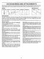
ACCESSORIES
,llllll i,
AN
ATTACH
ENTS
iii
These accessories and attachments were available when the unit was purchased, They are also available at most Sears retail outlets,
catalog and service centers. Most Sears stores can order these items for you when you provide the model number of your tractor.
EN GI NE
SPARK PLUG
MAI NTE NAN CE
MUFFLER
AIR FILTER
GAS CAN
ENGINE OtL
STABILIZER
BLADES
BELTS
PERFORMANCE
Sears offers a wide variety of attachments that fit your vehicle
Many of these are listed befow with brief explanations of how they
can help you. This list was current at the time of publication; however, it may change in future years - more attachments may be added,
changes may be made in these attachments, or some may no longer be available or fit your model. Contact your nearest Sears
store for the accessories
and attachments
that are available for your unit,
Most of these attachments
attaching and detaching
do not require additional hitches or conversion
PERMANEX BAGGER lets you collect
grass clippings and
leaves for a healthier, nearer looking lawn
Two Permanex
containers hold 30-gallon plastic bags,
LAWN SWEEPERS
let you collect grass clippings and leaves,
LAWN VAOS for powerful collections of heavy grass clippings
and leaves Wand attachment to pick up debris in hard-to-reach
places
CARTS make hauling easy. Variety of sizes available.
ROLLER for smoother lawn surface,
36-inch wide, I8 inch
diameter water-tight drum holds up to 390 Ibs. of weight. Rounded
edges prevent harm to turf. Adjustable scraper automatically
c_eans drum.
SPREADER/SEEDERS
make seeding, fertilizing, and weed kilting easy. Broadcast spreaders are also useful for granular deicers and sand.
CORING AERATOR takes small plugs out of soil to allow moisture and nutrients to reach grass roots. 36-inch swath
24
hardened steel coring tips, 150 Ib capacity weight tray.
AERATOR promotes deep root growth for a healthy lawn Ta*
pered 2.5" steei spikes mounted on 10-in. diameter discs puncture holes in soil at close intervals to let moisture soak in Steel
weight tray for increased penetration,
DETHATCHER loosens soil and flips thatch and matted leaves to
lawn surface for easy pick up. Twenty spring tine teeth. Useful
to prepare bare areas for seeding. Available for front or rear
mounting.
SPRAYERS use 12-voit DC electric motor that connects to the
tractor battery or other 12-volt source.
Includes booms for
automatic spraying when puffing, and hand held wand for spot
spraying
Wand has adjustable spray pattern. For applying
herbicides, insecticides, fungicides, and liquid fertilizers•
kits (those that do are indicated) and are designed for easy
SNOW BLADE for snow removal only
14-inch high, 42-inch
wide blade clears 38 inch path when angled left or right Raises,
lowers with side lever. Adjustable skids; replaceable, reversible
scraper bar (Use with tire chains, wheelweights, or rear drawbar
weight )
SNOW'FHROWER has 40-inch swath. Drum-type auger handles
powdery and wet/heavy snow. Mounts easily with simple pin
arrangement. Discharge chute adjusts from tractor seat 6-inch
diameter spout discharges snow t0 to 50 feet. Lift controlled at
tractor seat. (Use with chains, wheel weights, or rear drawbar
weight )
TIRE CHAINS are heavy duty; closely spaced extra-large cross
links give smooth ride, outstanding traction.
WHEEL WEIGHTS for rear wheels provide needed traction for
snow removal or dozing heavy materials In pairs (30 lbs each )
TRACTOR CAB has heavy duty vinyl fabric over tubular steel
frame, ABS plastic top; clear plastic windshield offers 360 degree
visibility. Hinged metal doors with catch, Keeps operator warm
and dry Remove vinyl and windshields for use as sun protector
in summer
Optional accessories for tractor cab: tinted/tempered solid safety
glass windshtefd with hand operated wiper; 12-voit amber caution
light for mounting on cab top
TRACTOR COVER protects tractor from weather.
Made of
Evolution 3 fabric (water-repellent, extremely breathable, light
weight, soft, non-abrasive, pliable in all temperatures, durable,
stain/tear/puncture resistant, will not shrink or stretch)
i ,
u n n n n n i,nll
lul, ii ,,
I, u un,I,,,,HW,I,,I
CONTENTS OF HARDWARE
Parts
,
n,,,
Bag contents
shown
full size
PACK
Parts packed
separately
in carton
,,i ,u,,,,,,,
(2) Sheet
Seat
Screws
Meta!
#10-16 x 1/2
(1) Locknut
1/2o20
Steering
Wheel
(1) 2-t/4" Dis, Washer
Battery
Steering
Boot
(I) Shoulder' Bolt 5/t6q8
(1) Hex Bolt
1/2-13 x 1
vner's Manual
@
(1) Washer
17/32 x 1-3/16 x 12 Ga,
%'_Steering
Bushing
(1) Lockwasher
(2) Battery Carriage Bolts 1/4-20 x 7-I/2
(2) Hex Nuts 1/4-20
Steering Wheel
Adapter
i
(2) Washers
Wheel
Steering
Insert
O
1/2
@
(2) Hex Bolts 1/4-20 x 3/4
_
(2) Keys
9/32 x 518 x 16 Ga, (2) Lock Washers
1/4
Terminal Guard
7
I
I
I
I
I
I
I
I
1
I
I
(2) Wing Nuts t/4-20
15 ° Slope Sheet
6
Battery Caps
and Instructions
ASSEM
LY
ii iii iii, u.,
TOOLS
REQUIRED
FOR ASSEMBLY
A socket wrench set will make assembly easier
wrench sizes are listed,
(1) 5/16" wrench
INSERT
Standard
(2) 7118" wrenches
(1) 3/4" wrench
Tire pressure gauge
(1) 1/2" wrench
Screwdriver
(1) 9/16" wrench
Utility knife
1t
2-1/4" DIA, WASHER
When right and left hand is mentioned in this manual, it
means when you are in the operating position (seated behind the steering wheel),
TO REMOVE
UNPACK
STEERING
BUSHING
CARTON
•
Remove all toose parts from carton (See page 6)
•
Cut, from top to bottom, all four corners of carton and
lay panels flat
ATTACH
STEERING
WHEEL
(See Fig. 1)
•
Sfide the steering bushing over the steering shaft
•
Raise steering shaft forward until screw holes in dash
line up with steering bushing. Install two (2) sh@t
metal screws and tighten securely
\
•
•
Position steering boot over steering shaft
\
Place tabs of steering boot over slots in dash and push',k
down to secure
•
Slide steering wheel adapter onto upper steering shaft
•
Position front wheels of the tractor so they are pointing
straight forward
Position steering wheel so cross bars are horizontal//
•
,
(left to right) and slide onto adapter
/
Assemble large flat washer and 1/2-20 hex nut ar_tJ
tighten securely
•
Snap insert into center of steering wheel
•
Remove protective plastic from tractor hood
BEFORE
STEERING
BOOT
UNIT FROM CARTON
ROLLING
STEERING SHAFT
(SHIPPING
POSITION)
STEERING SHAFT
(ASS EMBLY POSITION)
FIG, 1
UNIT OFF SKID
(See Fig. 6)
IMPORTANT:
CHECK
FOR AND REMOVE
ANY
STAPLES 1N SKID THAT MAY PUNCTURE TIRES WHERE UNIT IS TO ROLL
OFF SKID.
•
Raise attachment lift lever to its highest position.
•
Release parking brake by depressing
pedal.
Roll unit backwards off skid
•
clutch/brake
7
AS E
LY
HOW TO SET UP YOUR TRACTOR
INSTALL
PREPARE
Adjust seat before tightening adjustment bolt,
BATTERY
(See Fig, 2)
•
CAUTION: Wear eye and face shield.
Wash hands or clothing immediately tf
accldent ally In contact with battery acid,
Do not smoke. Fumes from
battery acid are explosive.
charged
Read the instructions included with the
battery vent caps. Alwayswear gloves,
clotMng and goggles to protect your
hands, skin and eyes.
Remove cardboard packing on seat pan.
•
Place seat on pan and assemble shoulder bolt.
•
Assemble adjustment bolt, tockwasher and fiat washer
loosely, Do not tighten.
•
Tighten shoulder bolt securely,
•
Lower seat into operating position and sit on seat.
•
Slide seat until a comfortable position is reached
which allows you to press clutchib_ake pedal all the
way down (See Fig, 6),,
•
Get off seat without moving its adjusted position
•
Raise seat and tighten adjustment bolt securely.
Your unit has a battery charging system which is sufficient
for normal use However, periodic charging of the battery
with an automotive charger will extend its life
•
See instructions packed with vent caps in parts bag.
•
Fill battery with acid. Fill each celt until it reaches the
bottom of the vent wells Do not ovedill
•
Atlow battery to stand and settle for at least thirty
minutes After standing, check the level of acid
If
below the vent wells, add more acid until the correct
level is reached..
SEAT (See Fig. 3)
SEAT
SEAT PAN
\
SHOULDER
BOLT
While battery is standing (after adding acid) and later, while
battery is being charged, continue with assembly of unit
•
•
,
To maximize the life of your battery, it is necessary that
the battery be charged before use Use a 12 volt battery
charger. Charge battery at a rate of 6 amperes for 1
hour. Observe all safety precautions required for battery charging Failure to charge battery can result in a
shortened battery life.
ADJUSTMENT
BOLT
CHECK
•
Disposeofexcessbatte_acid
Neutralize acidfordisposal by adding it to four inches of water in a five gallon
plastic container. Stir with a wooden or plastic paddle
while adding baking soda until the addition of more
soda causes no more foaming.
•
VENT
DECK LEVELNESS
For best cutting results, mower housing should be propedy
leveled.
See TO LEVEL MOWER HOUSING" in the
Service and Adjustments section of this manual
CHECK
BELTS
CAP
FOR
PROPER
POSITION
OF
ALL
See the figures that are shown for replacing motion and
mower blade drive belts in the Service and Adjustments
section of this manual
Verify that the belts are routed
correctly_
VENTWELL
BATTERY
CELL ACID
LEVEL
FIG. 2
Reduce tire pressure to PSI shown in "PRODUCT
SPECIFICATIONS" on page 3 of this manual,
CHECK
Follow instructions on how to install battery.
CUT AWAY VIEW
TIRE PRESSURE
The tires on your unit were overinflated at the factory for
shipping purposes. Correct tire pressure is important for
best cutting performance.
Install the vent caps to cover the vent wells, Wash the
top of the battery with water to remove any acid, then
wipe dry,
Check battery case for leakage to make sure that no
damage has occurred in handling
LOCKWASHER
FIG. 3
Check the acid level after the battery is charged, If the
acid has fallen below the correct level, add distilled or
iron free water
•
•
, FLAT WASHER
CHECK
8
BRAKE
SYSTEM
After you learn how to operate your tractor, check to see
that the brake is properly adjusted. See "TO ADJUST
BRAKE" in the Service and Adjustments section of this
manual.
ASSEMBLY
INSTALL BATTERY
(See Figs. 4 & 5)
WING
NUT
TERMINAL
GUARD
ACCESS
DOOR
CAUTION: Do not short battery terminals. Before Installing battery, remove
metal bracelets,
wristwatch
bands,
rings, etco
Positive terminal must
first to prevent sparking
tal grounding,
I
be connected
from acciden1
•
Lift seat to raised position
•
Lower battery into fender welt with battery terminals
toward front of unit. Make sure battery rests in battery
tray
•
Be sure battery drain tube has not come loose and is
securely attached to drain in battery tray
•
First connect RED battery cable to positive (+) battery
terminal with hex bolt, flat washer, Iockwasher and hex
nut as shown Tighten securely
•
Connect BLACK grounding cable to negative (-) battery terminal with remaining hex bolt, flat washer, lockwasher and hex nut Tighten securely
•
•
•
•
BATTERY
BOLT
KEY
HOLE
Slide the two battery bolts through the terminal guard
and start the wing nuts onto the threads
f
Position terminaf guard over the battery as shown_
lower bolts into key holes and slide square shafts oy
bolts into slots of key holes°
\
Tighten wing nuts by hand making sure battery bolts
remain in slots of the key holes in the battery support.
Be sure terminal access doors are closed°
VENT
CAPS
BATTERY
DRAIN TUBE
FIG. 5
/CHECKLIST
BEFORE YOU OPERATE AND ENJOY YOUR NEW
TRACTOR, WE WISH TO ASSURE THAT YOU RECEIVE
THE BEST PERFORMANCEAND SATISFACTION FROM
THIS QUALITY PRODUCT.
PLEASE REVIEW THE FOLLOWING
Use terminal access doors for:
inspection for secure connections
ware).
(to tighten
BATTERY
TRAY
hard-
CHECKLIST'
At] assembly instructions have been completed
No remaining loose parts in carton
•
Inspection for corrosion.
•
Testing battery
•
Jumping (if required),
¢"
Seat is adjusted comfortably and tightened securely
•
Periodic charging,
/
All tires are properfy inflated (For shipping purposes,
the tires were over-inflated at the factory)
POSITIVE (+)
TERMINAL
POSITIVE
CABLE
(RED)
Battery is properly prepared and charged
1 hour at 6 amps)
,/
Be sure mower deck is properly leveled side-to-side/
front-to-rear for best cutting results
(Tires must be
properly inflated for leveling).
€" Check mower and drive belts. Be sure they are routed
properly around pulleys and inside all belt keepers
NEGATIVE ( - )
TERMINAL
NEGATIVE
(BLACK)
FLATWASHERS
(Minimum
CABLE
/
Check wiring See that all connections are still secure
and wires are properly clamped
WHILE LEARNING HOW TO USE YOUR TRACTOR, PAY
EXTRA ATTENTION TO THE FOLL OWING IMPORTANT
ITEMS:
HEX NUT
LOCKWASHERS
€"
Engine oil is at proper level.
•/
Fuel tank is filled with fresh, clean, regular unleaded
gasoline.
Become familiar with all controls - their location and
function. Operate them before you start the engine
HEX NUT
,/
FIG. 4
v"
9
Be sure brake system is in safe operating condition
KNOW YOUR TRACTOR
READ
THIS
OWNER'S
MANUAL
AND
SAFETY
RULES
BEFORE
OPERATING
YOUR
TRACTOR
Compare the illustrations with your tractor to familiarize yourself with the locations of various controls and adjustments,
this manual for future reference,
Save
IGNITION
ATTACHMENT
CLUTCH LEVER
SWITCH
_,...,.,,_LIFTLEVER
PLUNGER
ATTACHMENT
LIFT LEVER
LIGHTSWITCH_
THROTTL_CHOKE
CONTROL
f
\
CLUTCH/BRAKE
PEDAL
[
PARKING
MOWER DECK
HEIGHT ADJUSTMENT
POSITIONS
1
BRAKE
-'--_GEARSHIFT
LEVER
FIG. 6
Sears tractors conform to the safety standards of the American National Standards Institute_
ATTACHMENT CLUTCH LEVER: Used to engage the
mower blades, or other attachments mounted to your
tractor.
LIGHT SWITCH:
GEARSHIFT LEVER: Selects the speed and direction of
tractor.
ATTACHMENT LIFT LEVER: Used to raise, lower, and
adjust the mower deck or other attachments mounted to
your tractor_
LIFT LEVER PLUNGER: Used to release attachment lift
lever when changing its position.
Turns the headlights on and off_
THROTTLE/CHOKE
CONTROL:
controlling engine speed.
Used for starting and
CLUTCH/BRAKE
PEDAL:
Used for declutching
braking the tractor and starting the engine_
and
IGNITION SWITCH:
engine,
PARKING BRAKE LEVER: Locks clutch/brake pedal into
the brake position.
10
Used for starting and stopping the
, ,
,, ,,,
, ,,
i
OPERATION
your tractor or performing any adjustments or repairs We recommend wide vision safe_y
mask for over the spectacles or standard safety glasses, available at Sears Retail or
Catalog stores
HOW TO USE YOUR TRACTOR
TO SET
PARKING
BRAKE
(See
Fig. 7)
IGNITION
KEY
•
Depress clutch/brake pedal into full "BRAKE" position
and hold
•
Place parking brake lever in "ENGAGED' position and
release pressurefrom clutch/brake pedal Pedal should
remain in "BRAKE" position Make sure parking brake
will hold vehicle secure
STOPPING
ATTACHMENT
CLUTCH LEVER
"ENGAGED"
POSITION
\'X.,
'DISENGAGED
POSITION
'
THROTTLE/
CHOKE
CONTROL
LEVER
(See Fig. 7)
MOWER BLADES Move attachment clutch lever to "DISENGAGED"
sition
poPOSITION
GROUND DRIVE Depress clutch/brake pedal into full "BRAKE" position
•
Move gearshift
ENGINE •
lever to "NEUTRAL" position
"BRAKE"
POSITION
Move throttle control to "SLOW" position
IIBRAKE
PEDAL "DRIVE"
POSITION
Turn ignition key to "OFF" position and remove key
Always remove key when leaving vehicle to prevent
unauthorized use
•
GEAR
SHIFT
LEVER
"CLUTCH"
POSITION
Never use choke to stop engine
FIG. 7
TO USE THROTTLE
CONTROL
(See Fig, 7)
TO ADJUST
Fig. 6)
Always operate engine at full throttle
MOWER
CUTTING
•
Operating engine at less than full throttle reduces the
batterv charging rate and the engine cooling air flow
The position of the attachment
cutting height
•
Full throttle offers the best bagging and mower performance
,
TO MOVE FORWARD
Fig. 6)
AND BACKWARD
Move gearshift
Slowly release clutch/brake pedal to start movement
lever to desired
lift lever determines
the
Grasp lift lever
The cutting height range is approximately t-1/4 to 3-3/4"
The heights are measured from the ground to the blade tip
with the engine not running These heights are approximate and may vary depending upon soil conditions, height
of grass and types of grass being mowed
The direction and speed of movement is controlled by the
gearshift lever
•
Start tractor with clutch/brake pedal depressed and
gearshift lever in "NEUTRAL" position
•
(See
Press plunger with thumb and move lever to desired
position
(See
•
HEIGHT
The average lawn should be cut approximately 2-1/2
inches during the cool season and over 3 inches during
hot months For healthier and better looking lawns,
mow often and after moderate growth
position
•
11
For best cutting performance, grass over 6 inches in
height should be mowed twice
Make the first cut
relatively high; the second to desired height
OPERATUON
TO OPERATE
MOWER
(See Fig. 8)
Your' unit is equipped with an operator presence sensing
switch. Any attempt by the operator to leave the seat with
the engine running and the attachment clutch engaged will
shut off the engine,
•
Select desired height of cut
.
Engagemower
by slowly moving attachment clutch
lever to ENGAGED' position,
TO STOP MOWER - Move attachment clutch lever to
"DISENGAGED" position_
•
•
If stopping is absolutely necessary, push clutch/brake
pedal quickly to brake position and engage parking
brake
•
Move gearshift lever to 1st gear and be sure you have
allowed room for tractor to roll slightly as you restart
movement.
•
To restart movement, slowly release parking brake and
clutch/brake pedal.
•
Make at1turns slowly.
TO TRANSPORT
CAUTION:
DO NOT OPERATE THE
MOWER WITHOUT EITHER THE ENTIRE GRASS CATCHER, ON MOWERS
SO EQUIPPED, OR THE DISCHARGE
GUARD IN PLACE.
•
Raise attachment lift control to highest position.
•
When pushing or towing your unit, be sure gearshift
lever' is in "NEUTRAL" position.,
.
Do not push or tow unit at more than five (5) MPH
BEFORE
"ENGAGED"
ATTACHMENT CLUTCH LEVER
"DISENGAGED"
POSITION
POSITION
CHECK
ATTACHMENT
LIFT LEVER
HIGH POSITION
LOW
)SITION
STARTING
ENGINE
THE ENGINE
OIL LEVEL
(See Fig. 16)
•
The engine in your unit has been shipped, from the
factory, already filled with summer weight oil,,
•
Check engine oil with unit on level ground
•
Remove oil fill dipstick and wipe clean, replace and
screw cap tight, wait for a few seconds, remove and
read oil level. If necessary, add oil until "FULL" mark
on dipstick is reached Do not overfill.
°
For cold weather operation you should change oil for
easier starthg (see "OIL VISCOSITY CHART" in the
Maintenance section of this manual).
.
To change engine oil, see the Maintenance
this manual.
section in
ADD GASOLINE
•
Fill fuel tank, Use fresh, clean, regular unleaded gasoline. (Use of leaded gasoline will-increase carbon and
lead oxide deposits and reduce valve life),
IMPORTANT:
R,H,
RUNNER
WARNING:
Experience indicates that alcohol blended
fuels (called gasohol or using ethanol or methanol) can
attract moisture which leads to separation and formation of
acids during storage, Acidic gas can damage the fuel
system of an engine while in storage. To avoid engine
problems, the fuel system should be emptied before storage of 30 days or longer,. D_ain the gas tank, start the
engine and let it run until the fuel lines and carburetor are
empty. Use fresh fuel next season. See Storage Instructions for additional information,,
Never use engine or
carburetor cleaner products in the fuel tank or permanent
damage may occur.,
DISCHARGE
GUARD
FIG, 8
TO OPERATE
WHEN OPERATING
IN TEMPERATURES BELOW 32°F(0°C), USE FRESH,
CLEAN WINTER GRADE GASOLINE TO
HELP INSURE GOOD COLD WEATHER
STARTtNG_
ON HILLS
CAUTION:
DO NOT DRIVE UP OR
DOWN HILLS WITH SLOPES GREATER
THAN 15 °AND DO NOT DRIVE ACROSS
ANY SLOPE.
•
Choose the slowest speed before starting up or down
hills,
CAUTION;
•
Avoid stopping or changing speed on hills
•
If slowing is necessary, move throttle control lever to
slower position.
FILL. WIPE OFF ANY SPILLED OIL OR
TANK
NOTOR
OVERFUEL. FILLER
DO NOTNECK.
STORE,DO
SPILL
USE
GASOLINE NEAR AN OPEN FLAME,
12
FILL T'O BOTTOM OF GAS
,
=,,,=
,
, =
=,, ,,,,,,,,,,,, ,,
,,
m,m,L,
OPERATION
TO START
ENGINE
(See Fig. 7)
When starting engine for the first time or if engine has
run out of fuel, it will take extra cranking time to move
fuel from the tank to the engine
•
Depress the clutch/brake
brake.
•
Place gearshift lever in "NEUTRAL"
•
Move attachment clutch to "DISENGAGED"
•
Move throttle control lever to "CHOKE" position for
cold engine start
For warm engine start, move
throttle control to "FAST" position
•
pedal and set the parking
•
Drive so that clippings are discharged onto the area
that has been cut. Have the cut area to the right of
the machine. This will result in a more even distribution of clippings and more uniform cutting.
•
When mowing large areas, start by turning to the
right so that clippings will discharge away from
shrubs, fences, driveways, etc, After one or two
rounds, mow in the opposite direction making left
hand turns until finished (See Fig. 9).
position.
position
Turn ignition key clockwise to "START" position and
release key as soon as engine starts. Do not run
starter continuously for more than fifteen seconds
per minute. If engine does not start after several
attempts, move throttle control to "FAST" position,
wait a few minutes and try again
•
When engine starts, move throttle control to desired
position.
•
Allow engine to warm up for a few minutes before
engaging drive or attachment clutch.
,
NOTE: If at a high altitude (above 3000 feet) or in cold
temperatures (below 32 ° F), the carburetor fuel mixture
may ,need to be adjusted for best engine performance,
See TO ADJUST CARBURETOR
in the Service and
Adjustments section of this manual,
MOWING
,
,,
FIG. 9
•
If grass is extremely tall, it should be mowed twice
to reduce load and possible fire hazard from dried
clippings. Make first cut relatively high; the second
to the desired height
TIPS
•
Tire chains cannot be used when the mower housing is attached to unit
•
•
Mower should be properly leveled for best mowing
performance. See "TO LEVEL MOWER HOUSING"
m the Service and Adjustments
section of this
manual
Do not mow grass when it is wet, Wet grass will
plug mower and leave undesirable clumps
Allow
grass to dry before mowing.
•
Always operate engine at full throttle when mowing
to assure better mowing performance and proper
discharge of material.
Regulate ground speed by
selecting a low enough gear to give the mower
cutting performance as well as the quality of cut
desired.
•
When operating attachments, select a ground speed
that will suit the terrain and give best performance of
the attachment being used.
•
•
Use the runner on the right hand side of mower as
a guide.
The blade cuts approximately
an inch
outside the runner (See Fig. 8).
The left hand side of mower should be used for trim_
ming.
13
MAINTENANCE
MAINTENANCE
SCHEDULE
_"___/_o_,,_._
'_
AS
You
COMPLETE
REGU_R
SERVICE
ATES
Check Brake Operation
Check Tire Pressure
_
......
v'
,Check for Loose Fas!e,ners,,
,
Sharpen/Replace Mower Blades
T
0
Check Battery Level/Recharge
Clean Battery and Terminals
R
Check Transmission Cooling
J
J
Adjust Blade Belt(s) Tension
Adjust Motion Drive Belt(s) Tension
Check Engine Oil Level
Change Engine Oil
E
Clean Air Ffiter
N C!ean A!! Screen
G
.......
Inspect Mufffer/SparkArrester
I
Replace Oil Filter (If equipped)
N
,_2
....
E' g+ne
Co oi+og
F+os...................
v'
Replace Spark Plug
ReplaceAirFilter
PaperCa.ridge
Replace Fuel Filter
1 - Change more often when operating under • heavy toad or in high ambient
2 - Semite more often when operating in dirty or dusty cond{tions
GENERAL
temperatures
3 - If equipped with oil filter, change oil every 50 hours
4 ..Replace blades mere often when mowing In sandy sell
RECOMMENDATIONS
LUBRICATION
The warranty on this vehicle does not cover items that have
been subjected to operator abuse or negligence,
To
receive full value from the warranty, operator must main-
(_)
tain unit as instructed inthis manual
Some adjustments will need to be made periodically to
properly maintain your unit..
(_)
CHART
RK@
(If equipped)
(If equipped)
BEARING
BEARING
®
ZERK
Al! adjustments in the Service and Adjustments section of
this manual should be checked at least once each seasom
•
ENGINE(_)
Once a yea_ you should replace the spark ptug, clean
or replace air filter, and check blades and belts for
wear. A new spark plug and clean ai+ filter' assure
proper air.fuel mixture and help your engine run better
and last IongeL
BEFORE
ZERK
(_
CLUTCH PIVOT
EACH USE
•
Check engine oil level
•
Check brake operation
•
•
Check tire pressure,
Check for loose fastenei'&
(_) SAE 30 OR t0W30
MOTOR OIL API * SF/CC
(_) GENERAL PURPOSE
(_
14
REFER TO ENGINE
GREASE
MAINTENANCE
SECTION
IMPORTANT;
DO NOT OIL OR GREASE
THE PIVOT POINTS
WHICH HAVE SPECIAL
NYLON BEARINGS
VISCOUS
LUBRICANTS WILL ATTRACT
DUST AND DiRT THAT WILL SHORTEN
THE LIFE OF THE SELF-LUBRICATING
BEARINGS.
IF YOU
FEEL THEY MUST BE LUBRICATED,
USE ONLY A DRY, POWDERED GRAPHITE
TYPE LUBRICANT
SPARINGLY.
ii
AINTENANCE
i llll,ll
i
i i ......................
TRACTOR
TO SHARPEN
Always observe safety rules when performing any maintenance
Care should be taken to keep the blade balanced
An
unbalanced blade will cause excessive vibration and eventual damage to mower and engine,
•
TIRES
•
Maintain proper air pressure in all tires (See "PRODUCT SPECIFICATIONS" on page 3 of this manual),
•
Keep tires free of gasoline, oil, or insect control chemicals which can harm rubber
•
Avoid stumps, stones, deep ruts, sharp objects and
other hazards that may cause tire damage,
•
BLADE
(See Fig. 11)
The blade can be sharpened with a file or on a grinding
wheel Do not attempt to sharpen while on the mower
To check blade balance, drive a nail into a beam or wa!l
Leave about one inch of the straight nail exposed.
Place center hole of blade over the head of the nai! If
blade is balanced, it should remain in a horizontal
position if either end of the blade moves downward,
sharpen the hea W end until the blade is bafanced
BLADE CARE
CENTER
HOLE
For best results mower blades must be kept sharp The
blades can be sharpened with a file or on a grinding wheel,
We suggest they be sharpened or replaced after every 25
hours of mowing Check blades more often if mowing in
sandy conditions
•
Do not attempt to sharpen blades while they are on the
mower,
•
Replace bent or damaged blades.
BLADE
REMOVAL
(See Fig, 10)
•
Raise mower to highest position to allow access to
blades.
•
Remove hex bolt, tockwasher and flat washer securing
blade_
•
Install new or resharpened blade with trailing edge up
towards deck as shown.
•
Reassemble hex bolt, lockwasher and f{at washer in
exact order as shown.
•
Tighten bolt securely (30-35 Ft, Lbs, torque).
FIG. 11
IMPORTANT: BLADE BOLT IS GRADE 5 HEATTR EATED°
_ACKSHAF_
ASSEMBLY
FLANGES
FLAT WASHER
TRAILING
EDGE
UP
(GRADE5)*
*A GRADE 5 HEAT TREATED BOLT
CAN BE IDENTIFIED BYTHREE LINES
ON THE BOLT HEAD AS SHOWN AT
LEFT_
FIG. 10
15
MAINTENANCE
,
111 ,
,
11,,1,,1,, , ,,
BATTERY
, ,,,
,1,,,
,,
(See Fig. 12)
•
CUT AWAY VIEW
Remove oil fill dipstick° Be careful not to allow dirt to
enter the engine when changing oil.
Remove drain plug,
After oil has drained completely, replace oil drain plug
and tighten securely,
Refill engine with oil through oil fill dipstick tube, Pour
slowly, Do not overfill. For approximate capacity see
Product Specifications on page 3 of this manual,
Use gauge on oil fill dipstick for checking level. Be sure
dipstick cap is tightened securely for accurate reading.
Keep oil at "FULL" line on dipstick_
.
•
Acid solution level in each battery cell should be even
with bottoms of vent wells. Add only distilled or iron flee
water if necessary° Do not overfill.
=
Catch oil in a suitable container,
•
Your unit has a battery charging system which is sufficient
for normal use. However, periodic charging of the battery
with an automotive charger will extend it's life.
•
=H,
•
CAP
WELL
RECOMMENDEDSAE VISCOSITY GRADES
BATTERY
CELL ACID
LEVEL
-20 °
0°
32 _
60 °
80 °
100 °
FIG. 12
•
•
•
•
TO
Keep battery and terminals clean.
Keep battery bofts tight.
Keep vent caps tight and small vent holes in caps open
Recharge at 6 amperes for 1 hour,
CLEAN BATTERY AND TERMINALS -
OIL FILL DIPSTICK
Corrosion and dirt on the battery and terminals can cause
the battery to "leak" power.
•
Remove terminal guard_
•
Disconnect BLACK battery cable first then RED battery cable and remove battery from tractor.
.
Wash battery with solution of four tablespoons of baking soda to one gallon of water Be careful not to get
the soda solution into the cells.
•
•
•
•
Rinse the battery with plain water and dry
Clean terminals and battery cable ends with wire brush
until bright
Coat terminals with grease or petroleum jelly
Reinstall battery (See "INSTALL BATTERY" in assembly section of this manual).
DRAIN PLUG
FIG, 13
AIR FILTER
ENGINE
Your engine witl not run properly and may be damaged by
using a dirty air filter= Replace paper cartridge once a year
or after every 100 hours of operation, more often if used in
very dusty, dirty conditions.
•
Remove knobs and cover.
LUBRICATION
Change the oil after the first two hours of operation and
every 25 hours thereafter or at least once a year if the
tractor is not used for 25 hours in one year_
Check the crankcase oil level before starting the engine
and after each eight (8) hours of continuous use° Add SAE
30W motor oil or equativent
Tighten oil lill cap/dipstick
securely each time you check the oil level, SAE 5W-30
motor oil may be used to make starting easier in areas
where temperature is consistently 32 _ F or lower.
TO CHANGE ENGINE OIL (See Fig 13)
Be sure vehicle is on level surface.
•
Oil will drain more freely when warm.
•
Remove cartridge nut and replace cartridge.
•
Reassemble and tighten securely.
NOTE:
Determine temperature range expected before oii change,
All oil must meet APt service classification SD, SE or SF.
•
(See Fig. 14)
16
Do not attempt to clean or oil the paper cartridge.
,=, ,,
,,,
MAINTENANCE
MUFFLER
COVER
KNOB _
Inspect and replace corroded muffler and spark arrester (if
equipped) as it could create a fire hazard and/or damage.
T
SPARK
PLUGS
Replace spark plugs at the beginning of each mowing
season or after every 100 hours of use, whichever comes
first. Spark plug type and gap setting is shown in "PRODUCT SPECIFICATIONS" on page 3 of this manual
IN-LINE
FUEL FILTER
(See Fig. 16)
Fuelfilter should be replaced once each season. If fuelfilter
becomes clogged, obstructing fuel flow to carburetor, replacement is required.
•
With engine cool, remove filter and plug fuel line
sections,
•
Place new fuel filter in position in fuel line.
•
Be sure there are no fuel Iine leaks and clamps are
properly positioned.
•
immediately wipe up any spilled gasoline.
FIG. 14
AIR SCREEN
(See Fig. 13)
The engine air screen must be kept free of dirt and chaff to
prevent engine damage from overheating. Clean with a
wire brush or compressed air to remove dirt and stubborn
dried gum fibers.
ENGINE
COOLING
FUEL FILTER
FINS (See Fig. 15)
Remove any dust, dirt or oil from engine cooling fins to
prevent engine damage from overheating.
•
Remove oil fill dipstick and cover opening to prevent
entry of dirt,
•
Remove screws from blower housing and lift housing
off engine.
.
Remove the screws securing the starter housing and
lift housing off engine.
•
Use compressed air or stiff bristle brush to thoroughly
clean engine cooling fins_
•
To reassemble, reverse above procedure_
FIG. '16
CLEANING
BLOWER HOUSING
SCREWS
•
Clean engine, battery, seat, finish, etc, of all foreign
matter,
•
Keep finished surfaces and wheels free of all gasoline,
oil, etc,
•
Protect painted surfaces with automotive type wax,
SCREWS
SCREWS
We do not recommend using a garden hose to clean your
unit unless the electrical system, muffler, air filter and carburetorare covered to keep water out_ Water in engine can
result in a shortened engine life,
ENGINE COOLING FINS
STARTER
HOUSING
OIL FILL
DIPSTICK
SPARK
PLUG
FIG, 15
17
......................................
I,,L=
i i ,i
ERV CE A
CAUTION:
i i ill,i
,,,,,,
r
.
Depress
•
•
Place gearshift lever in "NEUTRAL" position.
Place attachment clutch in "DISENGAGED" position°
•
•
•
Turn ignition key "OFF" and remove key.
Make sure the blades and all moving parts have completely stopped.
Disconnect spark plug wire from spark plug and place wire where it cannot come in contact with
plug,
TO REMOVE
clutch/brake
pedal fully and set parking
TO INSTALL
MOWER
(See Fig. 17)
Remove mower blade drive belt from engine pulley
only (See TO REPLACE MOWER BLADE DRIVE
BELT" through step removing belt from engine pulley)
Pull retainer springs out of rear suspension trunnions,
Remove rear suspension trunnions from lift brackets.
Pull retainer springs from front hinge pins,
•
Slide mower under tractor with discharge guard to right
side of tractor
•
Install parallel link to front axle and mower with hinge
pins, Secure hinge pins with retainer springs
Install clutch rod in clutch lever and secure with retainer
spring
•
Lower attachment lift lever to lower suspension arms,
Slide trunnions through lift bracket holes and secure
with retainer springs_
,
Roll bett over engine pulley Make sure belt is inside all
pulley grooves and inside belt guides.
Raise attachment lift tever to raise mower,
Slide mower
TO LEVEL
IF AN ATTACHMENT OTHER THAN THE
MOWER IS TO BE MOUNTED TO THE
TRACTOR, THE R.H. AND L.H. SUSPENSION ARMS MUST BE REMOVED
FROM TRACTOR,
CLUTCH
LEVER
RETAINER
SPRING
ENGINE
PULLEY
MOWER
HOUSING
Adjust the mower while tractor is parked on level ground or
driveway
Make sure tires are properly inflated (See
"PRODUCT SPECIFICATIONS" on page 3). If tires are
over or under inflated, you will not properly adjust your
mower
SIDE-TO-SIDE
RETAINER
SPRING
ADJUSTMENT
(See Figs18 and19) -
•
Raise attachment lift lever to its highest position.
•
Measure height from bottom of deck curl to ground
level at front corners of mower Distance "A" should be
the same_
•
If distance "A" needs to be changed, snap out access
hole cover on left side of tractor above footrest.
CLUTCH
ROD
MF'T
BRACKET
(See Fig, 17)
Raise attachment lift lever to its highest position.
Remove hinge pins attaching parallel link to mower
and front axle
Raise lift lever to [aise suspension arms
out from under tractor,
MOWER
, N ,=
•
•
Remove retainer spring from clutch rod; pull clutch rod
out of clutch lever,
CLUTCH
ROD
,
brake.
= HN,l= ,m,,,m,,i
Mower will be easier to remove from the right side of uniL
IMPORTANT:
i_
BEFORE PERFORMING ANY SERVICE OR ADJUSTMENTS;
TRACTOR
•
i
D ADJUSTMENTS
.................................
•
'
RETAINER
SPRINGS
To raise left side of mower, loosen nut "B" and tighten
nut "C".
_PARALL,EL
To lower left side of mower, loosen nut "C" and tighten
nut "B".
HINGE
PINS
FIG. 17
18
•
When distance "A" is equal, securely tighten nuts "B"
and "C".
:
Replace access hole cover.
REAR SUSPENSION
ARM
\
BOTTOM
OF CURL
BOTTOM
OF CURL
=-t*
D'['_
REAR SUSPENSION
TRUNNION
D
GR OU ND J
LINE
FIG. 2O
\
NUT"E"
GROUND
LINE
REAR
SUSPENSION
TRUNNION
FIG. 18
REAR
SUSPENSION
ARM
NUT "F"
SIDE TO SIDE
ADJUSTMENT
TRUNNION
LIFTBRACKET
FIG. 21
FIG. 19
FRONT-TO=BACK ADJUSTMENT(See Figs. 20 and 2I) To obtain the best cutting results, the mower housing
should be adjusted so the rear is approximately 3/4 to 7/8"
higher than the front when the mower is in its highest
position,
Check adjustment on right side of tractor. Measure distance "D" at front and rear flanges of mower housing as
shown,
•
To raise rear of mower, loosen nut "E" on both rear
suspension arms. Screw both nuts "F" on both rear
suspension arms an equal number of turns.
•
When distance "D" is 3/4 to 7/8" higher at rear than
front, retighten nuts "E",
•
Recheck side-to-side
adjustment_
IMPORTANT:
WHEN ADJUSTING
REAR SUSPENSION
TRUNNIONS,
ALWAYS ADJUST BOTH
EQUALLY
SO
MOWER
WILL STAY LEVEL SIDE-TO-SIDE
19
tw
S1ERVUCEAN
TO ADJUST
MOWER
(See Fig. 22)
BLADE
DRIVE
ADJUSTMENTS
BELT
IDLER BELT
GUIDE
Your tractor has been manufactured with the ability to
readjust the mower blade drive belt to provide you with
longer belt life.
Remove the bolt, nut
rock shaft assembly.
,
Move extension spring from lower to upper end of
slot in rock shaft assembly and install bolt, nut and
the D-shaped washers (flat side of washers down),
ENGINE PULLEY
L.H,
MANDREL
With the engine off and the lift lever in the highest position, move clutch lever up slowly until resistance is felt.
If distance from bottom of slot in dash to clutch lever is
greater than 4-1/2 inches, adjustment is necessary.
*
Lower the mower deck for easier access.
•
BELT'
EXTENSION
and D-shaped washers from
R.H,
Tighten bolt and nut to secure the D-shaped washers (fiat side down as shown).
TO REPLACE
(See
Figs.
MOWER
22 and
BLADE
DRIVE
ROCK SHAFT
BELT
23)
The mower blade drive belt may be replaced without
tools Park the tractor on level surface Engage parking
brake For assistance, there is a belt installation guide
decal on the mower housing
BELT REMOVAL Place attachment
clutch in "DISENGAGED"
BRAKE
ROD
position,
•
Move attachment lift lever forward to lower mower to
its lowest position
•
Roll belt off engine pulley.
•
Pull belt off both mandrel pulleys.
•
Spring belt guide away from idler pulley and pull belt
off idler pulley
•
$iide belt from under extension spring
BELT INSTALLATION
SPRING
_'-.....
-
•
Slide belt under extension
•
Place belt around back side and in groove of both
mandrel pulleys.
•
Spring idler belt guide down and place belt around
rear side of idler pulley
.
Roll belt over engine pulley
•
Make sure belt is in all pulley grooves and inside all
belt guides
FIG, 22
BELT
GUIDES
spring,
FIG. 23
2O
ENGINE
PULLEY
$ERVUCE AND ADJUSTMENTS
i
ii
TO ADJUST
BRAKE
iii ill ii illll
,Ulllllllllll,l,,,i
TO REPLACE
Fig. 25)
(See Fig. 24)
Your unit is equipped with an adjustable brake system
which is mounted on the right side of the transaxle
Depress clutch/brake pedal and engage parking brake,
•
Measure distance between brake operating arm and
nut "A" on brake red,
tf distance is other than 1-1/2", disengage parking
brake, loosen jam nut and turn nut "A" until distance
becomes 1-1/2", Retighten )am nut against nut "A",
Engage parking brake and recheck distance,
Road test unit for proper stopping distance as stated
above, Readjust if necessary. If stopping distance is
still greater than six (6) feet in highest gear, further
maintenance is necessary
Contact
your nearest
Sears Service Center,
W_H
PARKING BRAKE
MOTION
DRIVE BELT (See
The tractor drive belt may be replaced without tools,
Park the tractor on level area, Engage parking brake,
For assistance, there is a belt installation guide decal on
bottom side of left footrest,
•
Remove mower (See "TO REMOVE MOWER" in this
section of this manual)_
•
Roll belt over top of transaxle pulley°
•
Roll beft over engine pulley and off idler,
•
Release parking brake, Pull belt as far as possible
over top of clutch pulfey.
•
Reset parking brake
Pull belt over top of clutch
pulley,
•
Pull belt out up through gearshift lever gate opening
to remove from tractor,
•
install new belt by reversing above procedure
IMPORTANT:
REPLACE ONLY WITH BELT LISTED IN
THIS MANUAL
if unit requires more than six (6) feet stopping distance at
high speed in highest gear, then brake must be adjusted.
•
:T
"ENGAGED"
NUT"A"
C LUTC H
NGINE
PULLEY
IDLER
BELT
NUT "A"
\
/
_opE_j
JAM NUT
/
-
ARMRATING
FIG, 24
VIEWED
FROM BOTTOM
FIG. 25
21
OF TRACTOR
m
SERVICE AN
i
i i
TO ADJUST
i lll
illllUlllllliHlll
i
STEERING
WHEEL
ADJUSTMENTS
i,!l,llll,ll,i
TO START ENGINE WITH A WEAK BATTERY
ALIGNMENT
(See Figs. 27 & 28)
If steering wheel crossbars are not horizontal (left to right)
when wheels are positioned straight forward, remove
steering wheel and reassemble per instructions in the
Assembly section of this manual
FRONT
CAUTION: Lead-acid batteries generate explosive gases. Keep sparks, flame
and smoking materials away from batteries.
Always wear eye protection
when around batteries.
WHEEL TOE-IN/CAMBER
The fiont wheel toe-in and camber are not adjustable on
your unit, If damage has occured to affect the front wheel
toe-in or camber, contact your nearest Sears Service
Center.
TO REMOVE
Fig. 26)
WHEEL
FOR REPAIRS
If your battery is too weak to start the engine, it should be
recharged.
If "jumper cables" are used for emergency
starting, follow this procedure:
IMPORTANT:
YOUR UNIT IS EQUIPPED WITH A 12
VOLT NEGATIVE GROUNDED SYSTEM,_ THE OTHER
VEHICLE MUST ALSO BE A 12 VOLT NEGATIVE
GROUNDED SYSTEM. DO NOT USE YOUR TRACTOR
BATTERY TO START OTHER VEHICLES_
TO ATTACH JUMPER CABLES •
Connect each end of the RED cable to the POSITIVE
(+) terminal of each battery, taking care not to short
against chassis.
•
Connect one end of the BLACK cable to the NEGATIVE (-) terminal of fully charged battery_
(See
•
Block up axle securely.
•
Remove hub cap, retaining ring and washers to allow
wheel removal (_ear wheel contains a square key - Do
not lose).
•
Repair tire and reassemble.
•
On rear wheels only: align grooves in rear'wheef hub
and axle, Insert square key.
•
Replace washers and snap retaining ring securely in
axle groove.,
.
Connect the other end of the BLACK cable to a panel
bott on the left side of the chassis, away from fuel tank
and battery,
TO REMOVE CABLES, REVERSE ORDER •
BLACK cable first from left side of chassis and fully
charged battery,
i
RED cable last from both batteries.
Replace hub cap,
WASHERS
RETAINING
RING
"POSITIVE
....
NEGATIVE"
(+)
!
HUBCAP
(-)
FIG. 27
_SGUAREKEY
(REARWHEELONL_
FIG, 26
FIG. 28
22
SERVICE AN
ADJUSTMENTS
ii
TO REPLACE
iiii NIIIII, ,NN,, ,,,,,,
,,,
I L,,JJUL_III JlJI,,UUL
FUSE (See Fig. 29)
HOOD
Replace with 30 amp automotive-type plug-in fuse. The
fuse holder is located in the engine compartment, directly
in front of the dash.
CONNECTOR
HOOD SPRING
FUSE
HOLDER
HINGEBRACKET
FIG, 29
TO REPLACE
HEADLIGHT
FIG. 30
Raise hood.
•
Pull bulb holder out of the hole in the backside of the
grill.
•
Replace bulb in holder and push bulb holder securely
back into the hole in the backside of the grill
•
Close hood.
INTERLOCKS
AND
[
BULB
•
HOOD PIVOT ROD
HINGE BRACKET
RELAYS
Loose or damaged wiring may cause your tractor to run
poorly, stop running or prevent it from starting.
•
Check wiring, See electrical wiring diagram in Repair
Parts section of this manual,
TO REMOVE HOOD, GRILL
ELS (See Fig's. 30 and 31)
AND SIDE PAN-
•
Raise hood°
•
•
Unsnap headlight wire connector,
Stand at side of tractor, Grasp hood and tilt forward
and lift off hinge brackets,
•
SLOT
FIG. 31
To reinstall,slide hood pivot rod into slot in hinge
brackets, and carefully reinstall hood springs,
23
,..............................
,i,J,J,J,J,,=,l
in =
u ,,,
,=it,,,
_*twm
SERVICE AND ADJUSTMENTS
nil
n
=
nln
FINAL SETTING -
ENGINE
TO ADJUST
THROTTLE
CONTROL
CABLE
•
Start engine and allow to warm for five minutes. Make
final adjustments with engine running and shift/motion
control lever' in "NEUTRAL" position.
•
Move throttle control lever to "SLOW" position. With
finger, rotate and hold throttle lever against idle speed
screw. Turn idle speed screw to attain 1750 RPM
•
While still holding throttle lever against idle speed
screw, turn idle mixture valve in (clockwise) until engine begins to die and then turn out (counterclockwise)
until engine runs rough. Turn valve to a point midway
between those two positions. Release throttle lever..
(See Fig. 32)
The throttle control has been preset at the factory and ad_dustmentshould not be necessary Check adjustment as
escribed below before loosening cable tf adjustment is
necessary, proceed as follows:
•
With engine not running, move throttle control lever
from "SLOW" to "CHOKE" position Slowly move lever
from "CHOKE" to "FAST" position
,
Check that holes "A" in govet nor control lever and hole
in governor plate line-up. If holes "A" are not aligned,
loosen clamp screw and move throttle cable until holes
are aligned. Tighten clamp screw securely.
ACCELERATION
•
GOVERNOR
CONTROL LEVER
GOVERNOR
CONTROL PLATE
TEST -
Move throttle control lever from "SLOW" to "FAST"
position. If engine hesitates or dies, turn idle mixture
valve out (counterclockwise) 1/8 turn. Repeat test and
continue to adjust, if necessary, until engine accelerates smoothly.
High speed stop is factory adjusted.
damage may result.
IMPORTANT:
HOLES "A"
CLAMP
SCREW
THROTTLE
CABLE
Do not adjust -
NEVER TAMPER WITH THE ENGINE
GOVERNOR, WHICH IS FACTORY SET
FOR PROPER ENGINE SPEED, OVERSPEEDING THE ENGINE ABOVE THE
FACTORY HIGH SPEED SETTING CAN
BE DANGEROUS
IF YOU THINK THE
ENGINE-GOVERNED
HIGH SPEED
NEEDS ADJUSTING, CONTACT YOUR
NEAREST
AUTHORIZED
SERVICE
CENTER, WHICH HAS PROPER EQUIPMENTAND EXPERIENCETO MAKEANY
NECESSARY ADJUSTMENTS
FIG, 32
TO ADJUST
CARBURETOR
(See Fig. 33)
THROTTLE
LEVER
The carburetor has been preset at the factory and adjustmerit should not be necessary. However, minor adjustment may be required to compensate for differences in fuel,
temperature, altitude or load. If the carburetor does Reed
adjustment, proceed as follows:
IDLE SPEED
SCREW
In general, turnig idle mixture valve in (clockwise) decreases the supply of fuel to the engine giving a leaner fuel/
air mixture, Turning the idle mixture valve out (counterclockwise) increases the supply of fuel to the engine giving
a richer fuel/air mixture
IMPORTANT:
DAMAGETOTHENEEDLEVALVE
AND
THE SEAT tN CARBURETOR MAY RE_
SULT IF SCREW IS TURNED IN TOO
TIGHT.
PRELIMINARY
SETTING -
•
Air cleaner assembly must be assembled to the carburetor when making carburetor adjustments.
•
Be sure the throttle control cable is adjusted properly
(see above).
•
With engine off turn idle mixture valve in (clockwise)
closing it finger tight and then turn out (counterclockwise) 1 full turn
IDLE MIXTURE
VALVE
24
FIG. 33
Immediately
prepareyourtractorforstorageat theendof
theseasonoriftheunitwillnotbeusedfor30daysormore,
CAUTION: Never store the tractor with
gasoline in the tank inside a building
where fumes may reach an open flame
or spark, Allow the engine to cool
before storing In any enclosure,
CJean entire tractor (See "CLEANING" in the Maintenance section of this manual).
•
Inspect and replace belts, if necessary (See belt replacement instructions in the Service and Adjustments
section of this manual),
Lubricate as shown in the Maintenance section of this
manual.
•
•
Be sure that all nuts, bolts and screws are securely
fastened. Inspect moving parts for damage, breakage
and wear_ Replace if necessary.
•
Touch up all rusted or chipped paint surfaces; sand
lightly before painting,
Start the engine and let it run until the fuel lines and
carburetor are empty,,
•
Never use engine or carburetor cleaner products in the
fuel tank or permanent damage may occur,
Use fresh fuel next season,
NOTE= Fuel stabilizer is an acceptable alternative in minimizing the formation of fuel gum deposits during storage,
Add stabilizer to gasoline in fuel tank or storage container,
Always follow the mix ratio found on stabilizer container°
Run engine at least 10 minutes after adding stabilizer to
allow the stabilizer to reach the carburetor° Do not drain the
gas tank and carburetor if using fuel stabilizer.,
When
it thorblades
or rust
,
Drainthefueltank,
•
•
TRACTOR
Remove mower from tractor for winter storage.
mower is to be stored for a period of time, clean
oughly, remove all dirt, grease, Jeaves, etc. Give
and underside of housing a good coat of grease
preventative. Store in a clean, dry area.
.
ENGINE
OIL
Drain oil (with engine warm) and replace with clean engine
oil,, (See "ENGINE" in the Maintenance section of this
manual).
CYLINDERS
•
Remove spark plug(s)_
°
Pour one ounce of oil through spark plug hole(s) into
cylinder°
•
Turn ignition key to "START" position for a few seconds
to distribute oil.
,
Replace with new spark plug(s)o
OTHER
BATTERY
•
Do not store gasoline from one season to another.
•
Fully charge the battery for storage.
•
•
After a period of time in storage, battery may require
recharging.
Replace your gasoline can if your can starts to rusL
Rust and/or dirt in your gasoline will cause problem&
•
,
To help prevent corrosion and power leakage during
long periods of storage, battery cables should be
disconnected and battery cleaned thoroughly (see "TO
CLEAN BATTERY AND TERMINALS" in the Maintenance section of this manual).
tf possible, store your unit indoors and cover it to give
protection from dust and dirL
•
Cover your unit with a suitable protective cover that
does not retain moisture. Do not use plastic. Plastic
cannot breathe which allows condensation to form and
will cause your unit to rust°
IMPORTANT:
NEVER
COVER TRACTOR
WHILE
ENGINE AND EXHAUST AREAS ARE STILL WARM
After cleaning, leave cables disconnected and place
cables where they cannot come in contact with battery
terminals,
Be sure battery drain tube is securely attached to drain
in battery tray
ENGINE
FUEL SYSTEM
IMPORTANT:
IT IS IMPORTANT TO PREVENT GUM
DEPOSITS FROM FORMING IN ESSENTIAL FUEL
SYSTEM PARTS SUCH AS CARBURETOR, FUEL FILTER,
FUEL HOSE, OR TANK DURING STORAGE. ALSO,
EXPERIENCE iNDICATES THAT ALCOHOL BLENDED
FUELS (CALLED GASOHOL OR USING ETHANOL OR
METHANOL) CAN ATTRACT MOISTURE WHICH LEADS
TO SEPARATION AND FORMATION OF ACIDS DURING
STORAGE
ACIDIC GAS CAN DAMAGE THE FUEL
SYSTEM OF AN ENGINE WHILE IN STORAGE
25
TROUBLESHOOTING
PROBLEM
CAUSE
CORRECTION
iiiii
Will not start
POmNTS
n iiii nnl i UUll
1.
Out of fuel.
t.
F_llfuettank
2.
3.
4
5.
6.
7.
Engine not"CHOKED"properly.
Engine flooded.
Bad sparkplug.
Dirty a{r filter.
Ditty fuel filter.
Water In fuel.
2.
3.
4.
5_
6.
7.
See TO START ENGINE in operation section.
Wait several minutes before attemptfng to start.
Replace spark plug.
Clean/replace air filter.
Replace fuel filter.
Drain fuel tank and carburetor, refill tank with fresh
&
9.
10.
Loose or damagedwldng.
Carburetor out ofadjustmerit.
Engine vaives out of adjustment.
8.
9.
10.
Hard to start
1
2
3.
4.
5.
6.
7.
8.
Dirty a_r _ter
Bad sparkplug.
Weak or dead battery.
D_rty fuel filter.
Stale or dirty fuel
Loose ot damagedwlrlng_
Carburetor out of adjustment.
Engine valves out of adjustment
1.
2_
3.
4.
5.
6.
7.
8.
Engfhe will not turn over
1.
Clutch/brake pedal not depressed
Attachment clutch Is engaged.
Spark plug wire is disconnected.
Weak or dead battery_
Blown fuse.
Corroded battery terminals
Loose or damaged wiring.
Faulty Ignitlan switch.
Faulty solenoEdor starter
Faulty operator presence swltch(es).
2.
4_
5
6
8.
9
10
gasoline and replace fuel filter.
Check allwlring.
Contact Sears Sewice Department.
Contact Sears Service Department.
Clean/replace air filter.
Replace spark plug
Recharge or replace battery.
Replace fuel filter,
Drain fuel tank and refill with fresh gasoline
Check all wiring.
Contact Sears Service Department.
Contact Seats Service Department.
1.
2.
3.
4.
5.
6
7.
8
9
10.
Depress Clutch!brake pedal
Disengage attachment clutch
Connect wire to spark plug
Recharge or replace battery.
Replace fuse.
Clean battery terminals.
Check all wiring.
Check/replace ignlt{on switch.
Check/replace solenoid or starter.
Contact Sears Service Department.
\
Engine clicks but will not
start
1
2.
3,
4_
Weak or dead battery.
Corroded battery terminal&
Loose or damaged wiring.
Faultysolenotd or starter.
1
2_
3.
4_
Recharge or replace battery.
Clean battery terminals.
Check al_wiring.
Check/replace solenoid or starter.
Loss of power
1.
2.
3.
4.
5,
6
7.
8
9.
Cutting too much grass/foe fast.
Throttle In "CHOKE" position.
Build-up of grass, leaves and trash under mower_
Dirty air filter.
Low oil laveildlrty oil
Faulty sparkplug.
D_rty fuel filter,
Stale or dirty fuel
Water in fuel
1.
2.
3.
Set In "Higher Cut" position/reduce speed.
Adjust throttle control.
Clean underside of mower housing.
4.
5.
6.
7.
8
9.
Clean!replace air filter.
Check ott level/change oil
Clean and regap or change spark plug.
Replace fuel filter
Drain fuet tank and refill with fresh gasoline.
Drain fuel tank and carburetor, refilt tank with fresh
10.
I
12.
13.
14.
15.
Excessive vibration
Spark plug wire looser
Dirty engine air screen/fins
Dirty/clogged muffler.
Loose or damaged wiring.
Carburetor out of adjustment.
Engine valves out of adjustment.
1,
2
Worn, bent or loose b/ode.
Bent blade mandrel,
3
Loose/damaged
10.
11o
12.
13.
14.
15.
1.
2
3
part(s)
26
gasoline and replace fuel _ter.
Connect and tighten spark plug wire.
CFean engine air screen/fins
Clean/replace muffler.
Check alt w_r{ng_
Contact Sears Service Department.
Contact Sears Service Department.
Replace blade. Tighten blade boll
Replace blade mandrel.
Tighten loose part(s). Replace damaged parts.
_:
ii HIIIIIIIIll
I
TROUBLESHOOTING
CAUSE
PROBLEM
POBNT$
CORRECTION
Engine contlnuas to run
when operator leaves seat
with attachment clutch
engaged
1
Faulty ope_to_sa_
Poorcut-uneven
1.
2,
p_sence
cont_l
system
1
Check widng, switches and connections If not
corrected, contact Sears Service Department,
Worn, bent or loose blade
Mower deck nottevel.
1.
2.
Replace blade
Tighten blade bolt,
Level mower deck
3_
4,
Build-up of grass, leaves, and trash under mower
Bent blade mandrel
3.
4.
CIean underside of mower housing.
Repiace blade mandrel.
Mower blades will not
rotate
1,
Obstruction
2_
3,
4,
5
Mower drive belt out of adjustment,
Worn/damaged mower drive belt.
Frozen idler pulley
Frozen blade mandrel.
1,
2,
3.
4,
5.
Remove obstruction.
Adjust mower drive belt.
Replace mower drive beltReplace Idler pulley.
Replace blade mandrel.
Poor grass discharge
1.
2.
3.
4
Engine speed too slow
Travel speed too fast
Wet grass
Mower deck not ]eve],
t.
2r
3.
4,
Place throttle control in "FAST' position.
Shift to slower speed
AI]OW grass to dry before mowing
Level mower deck°
ii
5.
6
7
8,
9.
I0
Head_ight(s) not working
(_f so equipped)
Battery will not charge
in clutch mechanism,
Low/uneven tire air pressure.
Worn, bent or loose bEade.
Build-up of grass, leaves and trash under mower.
Mower drive belt worn or out of adjustment
Blades tmproperlytnstalled
improper blades used,
5.
6o
7,
8,
9.
10,
Check tires for proper air pressure,
Replace/sharpen
b]ade. Tighten blade bolt.
Clean underside of mower housing
Replacetadjust mower drive be[tr
Relnstall blades sharp edge downReplace with blades listed in this manual-
1,
Sw{tch is"OFF"
2.
3,
4.
5
Bufb(s) burned out.
Faulty Itght switch,
Loose or damaged wiring
Blown fuse
1.
2.
3
4_
5,
Turn switch "ON".
Replace bulb(s).
Checklrep[ace flght switch
Checkwtrlng and connections,
Replace fuse.
12.
Bad battery ceil(s).
Poor cable connections
1.
2,
Replace battery.
Check/clean aF[ connections.
3.
4,
Fautlyregulator
(if so equipped).
Faulty alternator
3.
4
Replace regu/ator_
Replace alternator.
27
i
ill
illlll i
illlllllll
SERVICE NOTES
ill i lllllllllllllll,ll
i, ii,
28
REPAIR PARTS
12.5 HP 38" RIDING
LAWN TRACTOR
-- MODEL NUMBER
917.255520
SCHEMATIC
÷Ill-BATTERY
cello
RED
[
RED
FUSE 30 AMP
!
STARTER
WHITE
1
?OLENO,O
|
IGNITION SWITCH
--_
'%.
Of,'
,_J
,O"_---O,
'I
i
......
L
I
I
I
]
BLACK
I
CLUTCH/BRAKE
(PEDAL UP)
..__.._
-_
BLACK
t
,
8LAC4K
SEAT
SWITCH
(NOT OCCUPIED)
ATT'MENT CLUTCH
(CLUTCH OFF)
BLACK
-
iGNITiON
UNIT
_.._____@
PLUG
RED
-..
AMPS DO
@ 3600 RPM
(BATTERY
IGNITION
SWITCH
POSITION
CIRCUIT
OFF
ON
START
M+G
B+L
B+S
®
NON-REMOVABLE
CONNECTIONS
REMOVABLE
CONNECTIONS
29
" 2.0VOLTS AC {MIN)
IN LINE)
NOTE
YOUR TRACTOR IS EQUIPPED
WITH A SPECIAL ALTERNATOR
SYSTEM, THE LIGHTS ARE NOT
CONNECTED TO THE BATTERY,
BUT HAVE THEIR OWN
ELECTRICAL SOURCE°
BECAUSE OF THIS, THE BRIGHTNESS OF THE LIGHTS WILL
CHANGE WITH ENGINE SPEED
AT IDLE THE LIGHTS WiLL DIM
AS THE ENGINE tS SPEEDED UP,
THE LIGHTS WILL BECOME
THEIR BRtGHTEST,
---_'_-----
ALTERNATOR
"X
" 5AMPS
@ tl VOLTS AC @ 3600 RPM
'.....
_,
HEADLIGHT
SWITCH
(OFF)
WIRING INSULATED
I
[
_
_
I HEAD
I LIGHTS
_._-"'
CLIPS
NOTE: If wiring ins_dated clips were removed for servicing of unit, they should
be replaced to properly secure your wiring.
F
30