1
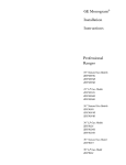
GE Monogram ®
Installation
Instructions
with
Optional Trim Kit
Installation
Instructions
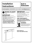
Built-In
Dishwashers
Modd._
ZBD 5600
ZBD5700
ZBD 5 900
gefl)re you begin - Read these instructions
completely
and carefldly.
IMPORTANT
- Save these ii1structioi1s for local inspector's
use.
IMPORTANTOBSERVE ALL GOVERNING
CODES AND ORDINANCES.
Note to Installer - Be sure to leave these instructions
with tile Consmner.
Note
to (:onsumer
- Keep
these
instructions
with your
Use and
Care Book tot flmue
grounded.
See "Power
i'elei'ellce.
IW:I
_i_R
fl
This appliance
must
be properly
_ ;_ | [_$'_ _ iT]]_ kl| lira Cet apvareil
dolt _tre correctemeut
Consulter
_<Alimentation
_lectrique
If tile dishwasher
is a new installation,
most of
tile work must be done beflwe tile dishwasher
is moved into place. If this dishwasher
is
replacing
another
dishwasher,
tile comaections
must be checked
tor compatibility
and replaced as necessary.
94 hours
Con_n_
local
For Monogram
1-888-880-3030.
service
For Monogram
1-800-626-2002.
Parts
Design
Models
Product
service
in your
mis _ la terre.
- page 8.
Installation
of this dishwasher
requires
basic
mechanical
and electrical
skills. Proper
installation
is tile responsibility
of tile installer. Product
failure due to improper
installation
is not covered under tile GE
service is required.
• Use this appliance
purpose.
only tot its intended
area,
• Ce lavewaisselle
in Cmlada,
and Accessories,
8.
• This dishwasher
must be installed
to allow
fin" flmn'e removal ti'om tile enclosure
if
a day, 7 days a week.
If vou received a damaged
dishwashei _,you
should immediately
contact vom _ dealer or
builder.
For Monogram
1-800-444-1845.
page
Appliance
_'al'rallty.
See tile Use & Care
Guide for warranty
infln'mation.
If vou have a question
concerning
tile installation of this product,
call tile GE Answer
(:enter ® Consmuer
hfformation
Service at
800.696.9000,
Supply",
a permettre
l'enceinte
call
Information
Available .............................................
Dimensions
.......................................
dolt _tre install_
la sortie ult_riem'e
en cas d'intervention,
de thcon
de
• I1 ne flint utiliser cet appareil
que pour
l'usage pore" lequel il a 6t6 construit.
Installation
3
3
Adwmce Plmming
..........................................
Standard
Installation
in 24" Deep Cabinets.
Optional
Trim Kits .........................................
Corner
Installation
.........................................
3
4
4
4
Installation
Preparation
Parts Supplied
.................................................
Materials You _]11 Need ................................
Tools xkm Will Need .......................................
5
6
6
Prepare
tile Opening
.....................................
Water Supply ...................................................
Power Supply ..................................................
Prepare
Drain Plmnbing
...............................
7
7
8
9
Step 1 Remove Wood Base ..........................
Step 2 Install Leveling
Legs
and Toekick Brackets
.................................
10
Step 3 Install Water Inlet Fittings ................
Step 4 Install Power Cord ............................
Step 5 Level the Dishwasher.
.......................
Step 6 Slide Dishwasher
into Opening
.......
Step 7 (kmnect
_Vatei _ Line .........................
Step 8 Install Drain Line ..............................
Step 9 (kmnect
Electrical
............................
Step 10 Secm'e Dishwasher
to
Co/mtertop
or Cabinetry
...........................
Step l 1 Install Toekick Assembly
................
Step 19 Install Side Filler Strips ..................
ll
11
12
19
19
13
13
10
14
15
15
Panel Kits
ZPF25 Door
Panel
Kit ..................................
16
1/4" Thick
ZPF75 Door
Custom Door Panel
Panel Kit ..................................
19
3/4"
Thick
Custom
Door
Panel
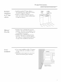
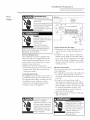
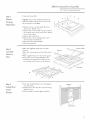
Design Information
Stai,less
Models
Available
ZBD5600 WW, ZBD5700
White Dishwashers
Steel
I, terior
Dishwasher,s
WW
ZBD5600 BB, ZBD5700 BB
Black Dishwashers
ZBD5900 SS
Stainless Steel Dishwasher
These
dishwashers
adaptable
are
to virtually
designed
any
for
versatility,
installation.
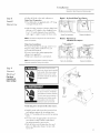
These models have a hill length trimless door
without
the traditional
access panel, The
black and white models can be customized
with decorative
material.
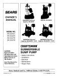
Product
A-34"
panels
Min. adjustable
of wood
or other
G
to 35" max.
Dimensions
B - 23-5/8"
C - 23-1/2" total depth
D -4" max., 2-7/8" rain.
E- 5" escutcheon height
F - Adjustable, to 3-1/4"
G -25-1/4" from cabinets
face (depending on depth
of cabinets)
Toekick_
Advance
Planning
• The black and white models may be covered
with custom decorative
door panels of wood
or other materials
to match cabinetry.
See
"Optional
Trim Kits," page 4.
• The stainless steel model does not accept
custom panels.
• A custom toekick can be installed
to match
cabinet
toekick material.
A continuous
toekick may be installed to form an
unbroken
line at floor level.
-A continuous
toekick should be installed
in such a manner
that it can be removed
if
service
is reqtfired.
• Tub
flange
trim
is supplied
between
the
ac!jacent
cabinetrv.
• These
dishwashers
may
slight
gap
countertops
of stone
will
not
accept
See
"Secure
screws.
No
trim
14.
beneath
materials
that
kit required.
to cotmtertop
page
may
and
be installed
or other
dishwasher
ac!jacent cabinetry",
to conceal
dishwasher
or
Design
Inff)rmation
SlaDde,s,_
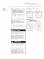
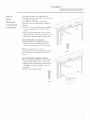
Standard
installation
in 24" de@
• With
thce
a 3/4"
place,
cabinets
01btional
7_im Kits
of ac!jacent
the
thick
to a(!jacent
the
cabinetry.
custon_
exterior
door
panel
is trimless
and
fits
l_Herior
Di,_hwa,_her,_
Cabinet
• Install
in standard
24" deep
cabinets:
- The dishwasher
door will be flush with
front
Sled
Resting
AgainstWall
in
flush
cabinetry.
• ZPF25_V, white
or ZPF25B,
black
custom
panel kit - Provides
flw the installation
of a
1/4" thick custom door panel, See page 16
flw installation
instructions.
• ZPF75_.
white
or ZPF75B,
black
custom
panel kit - Provides
flw a trimless appem_
mace using a 3/4" thick custom door panel.
See page 19 for installation
instructions.
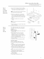
COrTler
installation
• For
a corner
between
or wall.
allow
and
2" clearai'Jce
ac!jacent
cabinet
Countertop
• Dishwasher
10 feet
installation,
dishwasher
fl'om
nltlst
sink
be placed
fl)i" proper
no
more
drainage.
than
Dishwasher
Door
Opening2" Minimum
Installation
hdbrmation
Slai_less
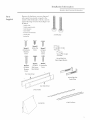
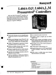
Parts
Remove
Supplied
other
parts
fl'om inside
outside
of the dishwasher.
against
included.
the
hardware
drawings
accessory
or
bag
taped
Check
to insure
that
Steel Interior
Dishwasher,_
and
to the
contents
all parts
are
2 toekick slides
2 teekick support brackets
2 side trim pieces
2-piece teekick
16 Screws (see illustration}
2 leveling legs
2 LevelingLegs
Junction box
"_
Screw B
Screw A
(2) Countertop
Mounting
Screws
(4)SideTrim
Screw C
Screws
(4)Toekick
Bracket
Screws
Leftand RightSide
ToekickSupportBrackets
Screw E
Screw F
Screw D
(2)Cabinet
(2)Toekick (2)JunctionBox
Slide ScrewsScrews
Mounting
Screws
ColorMatched
FrontToekick Panel
Leftand RightSide
ToekickSlides
InnerToel<ickPanel
2 PieceToekick
JunctionBox
2 SideTrim Pieces
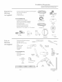
Installation
Preparation
Slai_le,s,_
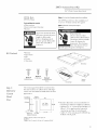
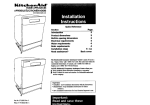
MateriaLs
You
Sleel
I_lerior
l)i,shwa,_her
%° elbow (3/8" NPTexternal thread on one end and opposite
Will Need:
end to fit hot water supply line)
(not supplied)
UL listed wire nuts (3)
Thread seal tape
Fer new iastallalioas
Electrical Cable
or Power Cord
90° Elbow
©
ealy:
Air gap for drain hose, if required
Screw Type Clamps
Waste tee for house plumbing, if applicable
Electrical cable or power cord, if applicable
Thread Seal
Tape
Screw type hose clamps
Strain relief for electrical connection
Hand shut-off valve (recommended)
Water line 3/8" O.D.min. copper or 1/2" O.D.min plastic.
Air
Gap
Wire Nuts
Hot Water Line
Shut-Off
Valve
Waste
Tee
Strain Relief
7boLs you
Will Need:
(Not Supplied)
Coupler
Flat Blade Screwdriver
Phillips head and flat blade screwdrivers
Adjustable wrench (6")
3/8", 5/16" and 1/4" nut drivers
Level
Carpenter's square
Phillips Head
Screwdriver
Measuring tape
Safety glasses
Safety Glasses
Flashlight
Fer new ieslallalio,
only:
Tubing cutter
Drill and appropriate bits
Holesaw set
Tubing
Cutter
Adjustable
Wrench
Flashlight
Hole
Saw Set
Measuring Tape
Drill
and Bits
,,,,,,,,,,,i
Level
dddddddddddd
Square
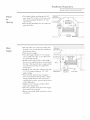
Installation
Preparation
Slai_le,_,_ Sled
the
Openin, g
• The rough
rain. deep,
The
opening
and
_5"
• The
pipes
cabinet
23-5/8"
l)i,_hwa,sher
opening
must be 24"
rain. to 24" max. wide.
height
should
be 34" rain.
should
be fl'ee of extraneous
II/ax,
opening
I_Herior
34"to35"
Underside
of Countertop
to Floor
and wires.
ThisWallArea
mustbeFreei
PipesorWires
24"Max
Water
Supply
• Hot water line may enter fl'om either side,
fl'om the rear, or fl'om the floor within the
shaded area shown.
offwater
supply.
• Cut a hole approximately
eter to admit water line.
be round and smooth.
//
• TtlI'n
1-1/2" in diamAccess hole must
shut-oil valve is optional,
and may be required
by
but
• Install the hot water line, using no less than
3/8" O.D. copper
tubing or 1/9" O.D.
plastic tubing.
• The water line must be long enough
to
torm a smooth
natural loop with no sharp
bends or kinks between
the cutout entry
and fill valve location,
of the dishwasher.
centered
Shut-offValve
\
• Install a hand shut-oil valve in the supply
line in an accessible
location,
such as under
the sink. (The
recomm ended
local codes.)
//J
at the fl'ont
• At!just the water heater to deliver 120°F
rain. water temperature.
• The water pressure
of the hot water supply
line must be 20 to 120 psi.
• Before connecting,
flush water line to clean
otlt debris.
//
d
X
\
I
\
\,
//
I
X
RightSide Entry
Approx.40"
,,_
ii
Li
ii
ii
Hot ::
ii
ii
ii
CabinetFace_
SideEntry ...... F_
Approx.30"
from Wall
2" from Floor
Installation
Preparation
Slai_le,_,_ Steel I_Herior Di,_hwa,_her,s
FORPERSONAL
SAFETY:
REMOVE
HOUSE
FUSEOROPEN
CIRCUIT
BREAKER
BEFORE
BEGINNING
INSTALLATION.
....
/
,
/C,
\
Receptacle t \\
Alternate
\
Location
DONOTUSEAN EXTENSION
CORDOR
ADAPTER
PLUGWITHTHISAPPLIANCE
FOLLOW
NATIONAL
ELECTRICAL
CODES
ORPREVAiLiNG
LOCAL
CODES
ANDORDINANCES.
Cabinet
2"
SI_CURITE
ILFAUTENLEVER
LEFUSIBLE
DELA
MAiSONOUOUVRiR
LEDISJONCTEUR
AVANTDECOMMENCER
L'INSTALLATiON.
ILNEFAUTPASUTILISER
DE
RALLONGE
NI D'ADAPTATEUR
DE
FICHE
AVECCETAPPAREiL.
[LFAUTRESPECTER
TOUSLES
CODES
D'ELECTRICITE
NATIONAUX
OULESCODES
ET
%GLEMENTS
LOCAUX
ENVIGUEUR.
Ground--/
Blacl<
_
Cabinet
Preparation
& Wiring:
• Wiring may enter fl'om either side, tile rear,
or fl'om tile floor within tile shaded area
sh
Electrical
Requirements:
These dishwashers
inust be supplied
with a
120 volt, 60 Hz power supply with an individual, properly
gr(mn(led
branch
circuit,
protected
by a 15 or 20 amp filse or circuit
breaker
or time delay filse.
• Wiring inust be 2 wire with gromacl.
• If electrical
supply does not meet the above
requirements,
call a licensed
electrician
befi_re proceeding.
own.
• Cut hole 1-1/2" max.
shaded area to admit
com_ected
to tile equipment-grounding
terminal
or lead on tile appliance.
Electrical
Connections:
is on tile
Tile electrical
com_ection
of the dishwasher.
cable
direct
be routed
extend
rear
• For
com_ections,
as illustrated.
fi)rward
a minimum
power
corcl
side
cable
inust
cable
must
of 24"
fl'om
c(mnections,
3-prong
type receptacle
sink cabinet
ilext
to the
the
the
The
right
the
wall.
receptable
18" fl'om
receptacle
more
than
• Allow
a(!jacent
THEiMPROPER
CONNECTION
OFTHE
EQUIPMENTGROUNDING
CONDUCTOR
CANRESULT
iN A RiSK
OFELECTRIC
SHOCK.
CHECK
WiTHA
QUALiFiED
ELECTRiCiAN
ORSERVICE
REPRESENTATIVE
iFYOUAREiN
DOUBT
WHETHER
THEAPPLIANCE
iS
PROPERLY
GROUNDED.
diameter
within tile
tile electrical
cable or
power cord. Tile hole must be fl'ee of sharp
edges. If tile cabinet wall partition
is metal,
tile edge of tile hole must be covered with a
rubber
protector.
• For
Grounding
Instructions:
This appliance
must be either cmmected
to a
grounded-metal
permanent
wiring system, or
an equipment-grounding
Coilductor
must be
rim with tile circuit conductors
and be
White
at least
the
dishwasher
install
6" and
cabinetr
not
wall of
Install
more
opening.
should
be at least
] S" off tile floor.
approximately
a
in the rear
dishwasher.
6" and
3" between
than
The
not
cable
and
v.
LEMAUVAISBRANCHEMENT
DU
CONNECTEUR
DEMISEA LATERRE
DE
L'EQUIPEMENT
PEUTCAUSER
UN
RISQUE
D'ELECTROCUTION.
ENCASDE
DOUTESURLAMISEA LATERRE
DE
L'APPAREIL,
CONSULTER
UN
ELECTRICIEN
QUALIFIE
OUUN
PREPOSE
DESERVICE.
Installation
Preparation
Slai_le,_,_ Sled
drain
plumbin, g
• Follow local codes and ordinances.
• Dishwasher
drain hose must not exceed
I_lerior
Di,_hwa,sher
Method 1 - Air Gap with Waste Tee or Disposer
10
feet in length for proper
drainage.
- Tire dishwasher
is supplied with a 3/4"
I.D. drain hose, 78" long. Add tip to 42"
length to the fhctory supplied
hose if
Usethis methodwhen waste tee or disposer connection is less
than 12" above the floor.
necessaiw.
• Dishwasher
must
be comaected
to waste
Mth an air gap (not supplied)
or 30"
minimum,
high drain loop (depending
local codes and ordinances)
to prevent
back flow into the dishwasher.
line
on
• An air gap must be used if waste tee or
disposer
com_ection
is less than 12" above
floor to prevent
siphoning.
• Install waste tee or disposer
and air gap
according
to the manufilcturer's
instructions.
Waste Tee Installation
DisposerInstallation
Method2- HighDrainLoop
with WasteTee or Disposer
Usethis methodwhen highdrainloopis at least30" abovethe
floor.
• Cut a hole in cabinet wall, approximately
1-1/2" in diameter
for drain hose.
• Install drain hose hook to underside
of
countei'top.
-Waste TeeInstallation
An air gap MUST BE USED if the drain
hose is connected
to x_aste tee or disposer
lower than 12" aboxe the floor lexel.
Failure to provide the proper
drain connecti(m height,
12", with air gap or 30"
minim um high drain loop will result in
improper
draining
of the dishwasher
which
IIlav
catlse
dalnage.
!
i
I
IL DOlT YAVOIR un dispositif
anti-retour
si le tuwm de vidange est branch_
hun tO
d'_gout
ou fi un broveur
d'ordures
qui est _l
Illoins de 30 cI/l (12 po) atl-(lesstls (hi sol.
Si le tuyau d'_)gout n'est pas branch,) h une
bom'Je hauteur,
au moiFJs 30 cm (12 po),
avec un dispositif
anti-retour,
ou si la
boucle d'()gout haute n'est pas {i une
hauteur
d'au moins 75 cm (30 po), le
lave-vaisselle
se vidange real, ce qui petit
causer des d&gfits.
4DisposerInstallation
Installation
StaD_le,s,_
Door Panel
• If you intend
to install custom door panels,
refer to installation
instructions
provided
in
this booklet.
The panels should be in place
beIore installing
the dishwasher.
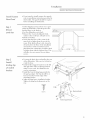
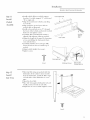
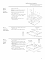
Step l
Cut
Remove
trader
finished
wood base
• Lay
hi, stall
Custom
the
shipping
carton
the dishwasher,
floor in the
the
dishwasher
• Remove
washer
on
wood
• lnsm'e
that
or
If the
elevated
floor
protect
the
its back,
cutout.
Pieces
placed
into
of the
dishscrews.
cutout
higher
than
the
kitchen
floor
is tile,
above
or higher
will allow
Di,_hwa,_her
base,
the
level
room.
I_Herior
use it as a pad
will
the 4 screws
holding
the
to the wood
base.
Discard
• Retain
same
and
This
kitchen,
Steel
the
floor
of the
the
rest
of the
wood
cutout
of the
it may
be
installation
base
floor
is the
may
be
to make
it level
than with the kitchen
floor,
This
fin" easy rein oval fl_r any fllture
service,
St@ 2
Install
• Un-wrap
the drain
of the dishwasher,
_velin, g legs
& toekick
• Install
brackets
crush
the
right
using
the
parts
least
pull
not
to the rear
to kink or
brackets
of the
each,
on
mounting
See
the
left
brackets
illustration
for
orientation,
• Install
the
support
sides
2 screws
correct
and
care
hose.
toekick
and
hose
Take
fl'ont
package.
2" fl'om
motmting
• A({just
Tighten
leveling
The
the
bottom
legs
legs
provided
should
edge
in
be at
of the
bracket.
leveling
legs
to installation
leveling leg locking
nuts
height.
on
the
rear.
2" Min.
Mounting Bracket
Screw C
Toekick Support Bracket
10
Installation
Slai_le,vs
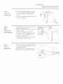
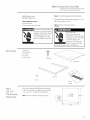
Step 3
Install
Water Inlet
• Install
the 90 ° elbow
Use thread
C()IIlp()/lI1
sealing
onto
tape
the water
or pipe
Sleel I_lerior
Di,shwa,sher
inlet.
thread
d,
• The 90 ° elbow
side, depending
should tace the left or right
on water line routing.
Fittin,_s
st@ 4
Install
powo cord
(g" used)
Skip this step
If dishwasher
will be wired
direct.
• Install strain relief ontojmaction
box and
tighten against incoming
wires.
• Strip 1/2" insulation
fl'om end of power
cord wires.
• Comaect incoming
wires to dishwasher
wires
using wire mlts of appropriate
size.
• Comaect tile white to white, black to black
and incoming
gro/md to green wire.
• Push all wires into thejm_ction
box and
secm'e cover with screws onto dishwasher
ti'all/e.
Note: Tile power cord and connections
II/[Ist
comply with tile National
Electrical
Code,
Section 429 and/or
local codes and
ordinances.
IMPORTANT: The p(mer cord illt/st be no
longer than 6 fl fl'om thejmlction
box to tile
plug. DO NOT PLUG IN PO_ ER CORD .AT
THIS TIME.
ScrewF
11
Installation
StaD_le,s,_ Steel I_lerior
Step 5
Level
the
Dishwasher
• Careflllly
upright
tile dishwasher,
taking
care not to bend tile leveling legs. Make
sure tile leveling leg locking nuts are
sectlre.
• Check to be sure tile dishwasher
is level and
at tile cutout
Step 6
Slide
Di,_hwa,_her
Level
And
Sides
height.
• Insert drain hose into tile hole
drilled in tile cabinet wall.
previously
Dishwasher
• Slide tile dishwasher
inches at a time.
into tile opening
a few
Into Openin, g
• As you proceed,
pull tile drain hose
through
tile cabinet wall under tile sink.
• If a power cord is used, guide tile end
through
a separate
hole.
• Check to be sure there is no interference
with waterline
Step 7
Connect
Water Line
or house
wiring.
• Tile water supply line should be flushed to
clear any foreign
material
before connecting to tile dishwasher.
• Make sure there are no sharp bends
kinks which could restrict tile water
or
flow.
HotWater
Supply
90° Elbow
12
Installation
Slaiule,vs
Step 8
• Follow
[nstall
Drain Line Preparation
• The dishwasher
is supplied
corrugated
drain hose.
Drain Line
• If the
all local
location
add
up
Use
3/4"
wall
copper
Note:
codes
and
requires
to 42"
length
inside
ordinances.
a longer
diameter
draiil
supplied
hose
to join
and
the
hose
hose,
hose.
thin
ends.
Total drain hose length must not exceed 10 feet for
Line
• (_om_ect
disposer
drain
previously
• SecHre
clamps
• Make
Waste Tee Installation
Method 2 - High Drain Loop
Fasten to underside
line
to air gap,
either
method
waste
tee
__
or
(not
sm'e
using
supplied).
drain
hose
ofcountertop
Fasten to underside
1 or 2 as
determined.
c(mnection
DisposerInstallation
with Waste Tee or Disposer
Installation
using
Di,shwa,sher
Method1 - Air Gapwith WasteTee or Disposer
proper drain operation.
Drain
Iulerior
with a 78" hmg
to the
coupler
Sleel
30"
appropriate
is not
30"
kinked.
Note: Removedrain plug before connecting to disposer.
Waste Teelnstallation
Disposerlnstallation
Dishwasher cannot drain if plug is left in place.
Step 9
lf house wiring is not 2-wire with a
Connect
by the installer. When house wiring is
Electrical
(Fordirect
connectionto
aluminum, be sure to use U.L. listed
anti-oxidant compound and aluminum__
ground wire,
to-copper
connectors.
a ground must be provided
housewiring)
Si le circuit de la maison n'a pas deux
ills, plus un fil de terre, Vinstallateur
dolt installer un fil de terre. Quand les
ills de la maison sent en aluminium, il
\
\
/
Screw F
faut prendre soin d'utiJiser une p_te
/
/
anti-oxydante et des connecteurs
aluminium a cuivre sur la liste UL.
Verify
that power
is turned
off
at the
/
/
source.
• Install a strain relief onto the junction
box
and tighten against the incoming
wires.
• Strip l/2" insulation
fl'om end of incoming
wires.
• Use wire mlts of appropriate
size and c(mnect white t()white,
black to black and
incoming
ground
to green wire.
• Push all wires into the junction
box and
place on dishwasher
fl'ame. Secure with
screws "g".
13
Installation
Stai_less
Step 10
5 cure
Dishwasher
to Countertop
or Cabinetry
Steel I_Herior
Dishwasher
To maintain
position
and alignment
the
dishwasher
nlust be secured to tile COUlltertop
or to a(!jacent
cabinetry.
If co/mtertop
is of stone or other hard
material,
secure the dishwasher
to a(!jacent
cabin ets.
• Check to be s/ire that dishwasher
to correct height and is centered
cutout.
is a(!justed
in tile
• Open and close dishwasher
door to insure
proper
operation
of tile door. If there is anv
binding
or rubbing,
reac!just leveling legs.
Secure dishwasher
to countertop:
• Drill pilot holes through
tile mounting
bracket and into tile underside
of tile
countertop.
Install
2 screws
"A" provided.
Note: Take special care to ensure
CO/lllterI//O/lIlt
screws are driven flush
do not damage
closed.
Secure
top of do()); when
dishwasher
to adjacent
• Remove
plastic
the dishwasher
plug buttoi_
fl'ame.
One
• Drill
the
pilot
holes
ac!jacent
through
cabinets,
tile
Install
so thev
door
is
cabinets:
on tile inside
(hi each side.
holes
and
2 screws
of
into
"D"
provided.
• Replace
plastic
plug
buttons.
Screw D
14
Installation
Slai_le,s,s
Step l l
[nstall
7bekick
Assembly
• Install toekick slides to toekick support
brackets.
Use slide stamped
"L" on left and
"R" on right side.
• Align fl'ont and ironer toekicks, matching
screw holes.
• Align toekick to second screw
toekick slide as illustrated.
hole
Sleel I_lerior
l)i,shwa,sher
FrontToel<icl<
Panel
in
• Install color matched
screws "E" through
the flxmt of the toekick and into the toekick
slides. Do not tighten screws.
• Carefldly,
slide assembly
back until it is
aligned with a(!jacent
cabinetry
toekick.
• A(!just the height of the panel by loosening
screws and sliding the fl'ont panel down,
even x_ith the floor.
InnerToel<icl<
LeftSide
Toekicl<
Slide
• Carefully,
hold the door and open flflly.
Ensure that door does not strike top of
toekick.
• A(!just toekick height
• Tighten
screws.
if necessary.
i:
Slidetoekick
out_
ScrewE
St@ 12
Install
Side 7?ira
AttachmentScrews
Pulltab while
Pushingtoekickin
• Side trim filler strips are packed with this
dishwasher. If the cabinet cutout is wider
than the dishwasher, install the filler strips
on both sides of the dishwasher to cover
gaps.
• Open the door fidlv.
• Place side trim against dishwasher tub and
install 2 screws, loosely on each side.
• At!just trim to correct width. Tighten screws.
Side
Trim
Screw B
15
ZPF25
Custom
l/4"
7, 5 B, Black
ZPI_2r
Tkick
Panel
(u,slom
Door
Kit
Pa_el
Moto: It is best that 2 peopleperformthis installation.
trim
ZPF2,cF_ _,, r White
Door
trim
The ZPF25 trim kit provides
thick custoln door panel.
Tools and Materials required
support
for 1/4"
• Phillips screwdriver
Moto: Maximumcustompanelweight is
10pounds.
• Gloves to protect against sharp edges.
To pre_ent
electrical
shock,
clisc(mnect electrical
pox_er
supply to dishwasher
before
changing
panels. Do not
operate
dishwasher
when
door asseinblv
is i'ei/love(l.
Pore" &viter les
&lectrocutions,
il flint
cl_brancher
l'alimentation
&lectriq ue du lave-vaisselle
event de changer
les
pam_eaux.
I1 ne thut pas
thire follctiollller
le lavevaisselle
Kit Contents
q uand
la porte
est cl&pos&e.
• Metal door
• 8 wood screws
• 6 "6" clips
• Door Trim
• 2 Door Springs
(8)Screws
Door Trim
"(;" Olips
2 Door
Springs
St@ l
Cut l/4"
• Cut
door
• The
bottom
be
cut
panel
at 1/4"
to the
left
and
radius.
dimensions
right
corners
shown.
should
See illustration.
Thick Custo"nz
Panel
to Size
Rote: The trim will conceal the cut edges of the panels.
1/4" Thick
DoorPanel
25-1/2"
23-1/8"
16
ZPF25
Custom
l/4"
• Open
Step 2
Remove
Existin, g
Metal
Door
the door
Door
Tkick
Panel
(ustom
Door
Kit
Pa_el
fllllv.,
Caution:
One person should hold the door
while the other backs out s('rex_s to prex eat
the metal door fron/falling.
• Remove
door
6 screws
fl'ame,
on the
Retain
inside
the
inner
screws,
• Remove
the 2 screws
with o-rings
located
in
the bottom
center
of the ironer door. Retain
screws
and o-rings.
• [x)eIuove the ()liter
• Remove
the
door
bracket
Assemble
Panel
• Retain
bracket
and
• Discard
metal
door,
• Place
the
s/li't_lce,
Step 3
to
Door
door,
2 screws
holding
to metal
door,
supplied
the
center
insulation,
metal
door
Deco
Oll a fiat
Panel
DoorTrim
• Place the custom panel on top of the metal
door.
• Place
supplied
• Press
trim
matched
on each
trim
to panel
over
and
the
custom
install
screws
provided.
side and 9 screws
panel.
the
Install
on the
color
3 screws
bottom.
_orPanel
s@ 4
[nstall Door
C_nter
Bracket
• Turn
ance
• Install
original
• Place
the assembled
side down,
center
door
door
bracket
over
onto
with
appear-
door
Insulation
using
screws,
insulation
around
support
bracket,
Install Screws
17
ZPF25
Custom
l/4"
Step 5
fnstall
As sembled
Door onto
Dishwasher
• Locate
the
"(7'
Place
one
screw
holes,
Note:
clips
clip,
flat
3 on
in the
side
parts
tip,
each
Tkick
Panel
Custom
Kit
Door Pa_el
package.
oxer
side
Door
each
of the
of the
door.
One personshould hold the door while the other installs
screws to preventthe door assemblyfrom falling.
• Hold
the assembled
door
to dishwasher
ironer door and slide tip against control
panel. Control
panel has posts that should
engage the 9 holes in the top of the metal
door.
• Install the original
o-rings.
Note:
center
screws and
Center screws and o-rings must be securely fastened to
preventfuture leaks.
• Install
flame,
Step 6
original
3 each
screx_ s to sides of imaer
side.
door
Door
The additional
weight of the custom panel
may require
that the heavy door springs be
installed.
Test Door Balance
5 rincs
• With one hand
the door filllv.
[nstall
under
the door,
slowly open
• Open and close the door to check t0r
proper
balance.
Correct
door balance
should prevent
the door fl'om raising by
itself fl'om a fifll open position
and prevent
the door fl'om talling heavilv.
• If the door talls heavil}; damage
will occur
ti'om repeated
use.
• Install one or both new springs provided.
Install
• Close
New
and
• Locate
washer.
Springs:
latch
the
door
spring
• Disengage
the
down
on
guide
out
the
of the
• Carefldly
and
rod.
the
that
• Reassemble
door.
of dish-
left
rod
and
the
guide
by pushing
slowly
pulling
the
tension
push
rod
spring
and
push
the
position.
on
guide
replace
has a yellow
the
side
mounting
release
remove
• Remove
spring
push
guide
dishwasher
on
the
fl'om
spring
the
with
the
into
the
marking,
rod
guide
original
position,
• Test door balance,
• Install
right
side
spring
if needed,
18
ZPF75
Custom
/4
ZPF75B,
ZPF75_,
Black
_ hite
Note:
Panel
Thick
Kit
(usi0m
l)oor
Panel
It is best that 2 people perform this installation.
The ZPF75 provides
fin" the installation
1/2" to 3/4" thick custom door panel.
Tools and Materials mqu#ed
• Phillips screwdriver
of
Noto: Maximumcustompanelweight is
10 pounds.
• Glovesto protect against sharp edges
• Nut driver
_To
prexent
discmmect
electrical
shock,
Pour
electrical
power
_)lectrocutions,
supply
to dishwasher
befin'e
changing
panels.
Do not
operate
dishwasher
when
door
reiilo','ed.
les
il thut
d_)brancher
assembly
l'alimentation
_lectrique
avant
is
du
lave-vaisselle
de changer
les
pmmeaux.
I1 ne thut pas
thire tinactimmer
le lavevaisselle
Kit Contents
&viter
quand
la porte
est d6pos6e.
• Metal door
• Support bracket
• Label
• 18 Screws
• 2 Door springs
Metal Door
Screw Y
(6) Not Used
Screw X
(1O)Wood Screws
Screw Z
(2) Support Bracket
Screws
Support
Bracket
Door Springs
St@ l:
The
Determine
the
can
Custom
appearance.
Panel
custoin
panel
same
nlanner
be seen
and
C0untert0p
__
,
-t
Sizes
should
be
constructed
in
as cabinet
doors.
All edges
must be finished
for the best
Custom
Panel Size
Cabinets Dim A_'
Top
3/4"Thick
Door Panel
• Measm'e
_Height
dimension
countertop
- Subtract
Allow
F
Floor
/ Bottom of
_ll_3/4" Max. _23-1/8"
Adjacent Cabinetry
5-1/8".
1/8"
countertop
-Add
behind
A, fl'om
to bottom
and
1/4".
Control
fin" gap
The
control
underside
of ac!jacent
panel
between
top
of control
custom
panel
of
cabinets.
height
bottom
is 5".
of
panel.
will
slide
tip,
panel.
_Height is equal to A minus 5-1/8" plus 1/4"
EXAMPLE:
_Height =30-1/2" minus 5-1/8" plus 1/4" is equal to 25-5/8".
19
ZPF75
Custom
/4
Step 2
• Open
Remove
Caution:
Thick
Kit
( u,stom Door Panel
flflly.
One person should hold the door while the other
2 "0" Rings
hacks out screws to preventthe metal door from falling.
Existing
Metal
tile door
Panel
Door
• Remove 6 screws on tile inside
fi'ame. Retain screws.
of tile
• Remove tile 2 screws with o-rings located
tile bottom
center of tile door. Retain
in
screws and o-rings.
• Renlove tile door.
• Remove
discard
insulation
and loam
metal door.
Step 3
• Install
[nstall Door
using screws "Z'.
• Place insulation
aroui]d
Center
new center
door
inserts,
bracket
onto
door
Supp!_:_!_acl<et
support
2- Depresslons_Fla
bracket.
t Face
i
i
Bracket
&
ScrewZ
Metallntegrated Door
Step4
Assemble
Custo' nz"
Pand
• Lay custom panel (m a fiat surtace,
ance side down.
appear-
• Place tile new metal door panel onto tile
back of tile custom door panel. Align sides
and top edges.
• Drill 1/8" pilot holes, 3/8" deep, through
the metal panel and into tile custom panel,
3 each side.
Drill 1/8" Holes
(3 EachSide)
ScrewX
1
• Secure custonl panel to metal door with
3 screws "X" on each side.
• Drill 1/4" pilot holes through tile top
return flange, approximately
1/4" deep.
Drill 1/4"
Holes
_mPanel
2O
ZPF75
Custom
3/4"
Step 5
Note:
Panel
Thick
Custom
Door Pa_el
One personshould hold the door while the other installs
screws to preventthe door assemblyfrom falling.
2 "0" Rings_
hi, stall
As s embled
• Check
Door onto
place.
• Hold
assembled
door
Dishwasho
ironer
door
and
up
panel,
The
control
to be sure
the
should
that
fl)am
slide
engage
metal
inserts
in
i Insert
to dishwasher
against
panel
the
are
control
has posts
9 holes
that
in the
top
Fo
of the
Insert l
panel,
• Install
the original
center
screws
mad
O-I'ings.
MoistureStrip
Note:
Kit
ControlPanel
PostHoles
Centerscrews and o-rings must be securely fastened to
prevent leaks.
• Install
original
fl'ame,
screws
3 each
to sides
of imaer
door
side.
fnstall
The additional
weight of the custom panel
may require
that the heavv door springs be
installed.
Door
Test Door
Step 6
Balance
• With one hand
the door flfllv.
under
the dooi,
slowly open
• Open and close the door to check tot
proper
balance.
Correct
door balance
Push
Rod
Guide
should prevent
the door ti'om raising by
itself ti'om a flfll open position
and prevent
the door ti'om thlling heavily.
• If the door fidls heavily, damage
will occur
fi'om repeated
use.
• Install one or both new springs
provided.
Install
• (]lose
dishwasher
door.
on
of dish-
New
and
• Locate
washer,
Springs:
latch the
door
spring
• Disengage
the
down
(m the
guide
out
• Remove
spring
the
that
• Reassemble
the
and
the
guide
by pushing
slowly
pulling
tension
push
rod
and
on the
guide
replace
a yellow
push
the
position.
the
spring
has
side
mounting
release
remove
rod
guide
of the
• Careflfllv
and
rod.
push
left
fl'om
spring
the
with
the
into
the
marking,
rod
guide
original
position,
• Test door balance.
• Install
right
side
spring
if needed.
21
ZPF75
Custom
3/4"
Step 7
fnstall
Custom
7b&ick
• Slip toekick slides
the metal tabs.
into guides
by pulling
• Hold custom panel against toekick
and mark screw hole locations.
Panel
Thick
Kit
( ustom
Door Pa_el
out
slides
• Remove toekick and drill 1/8" pilot holes.
• Remove toekick slides and secure panel to
slides with 2 screws each. Use screws "X'. If
panels are 1/2" thick, use caution when
driving these screws.
• Insert the assembled
toekick into the
support
tabs.
brackets
by pulling
out the metal
• Carefldl>
slide assemblv back until it is
aligned with ac!jacent cabinetrv
toekick.
• See product
installation
instructions
to
reinstall
the dishwasher.
• Carefldl>
hold the door and open fldly,
Insure that door does not strike top of
toekick.
ScrewX
PullTabWhile Pushingtoel<ickin
2_
Notes
Slai*_le,s,s
Sleel
I_lerior
l)i,shwa,sher
9_D°
NOTE: While performinginstaflations describedin this hook,
safeWglassesor gogglesshould beworn.
7_, obmhz V,e<ific hq;.mal_o_z
co_*cenzh_g a_9
_onsumer i_q_,w_<ttio_z ser vi< e <tl _qO0.626.2000--<_ly
lil_z< d_0 or _lighL
For Mo_mgv<tm Io<<d s_,rvic_, _z your <n_<_,_<dl
l -+_00-444-1 +_45. h_ C<_+_+_d<t
<<dl, l -+_8_,'-&_O-3030.
NOTE:
@
Monogram:
P_oduc_
Eleclric
There,>re,
subiecl
Io cha_+ge
implovemenl
is t c<mdmfil_g
male_ials_
will_<>_l
appearance
J_olice
ende
aJ_d
tvol
specilicalions
al (;ene_
are
d
Pub.
Part
Issue
49-5860-1
in USA
4, 1999
(N.D.
General Electric Company
Louisville, KY40225
No.
Primed
GE Appliarlces
458)
Number:
A
9/99
(82
0017x