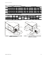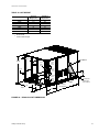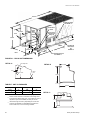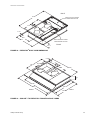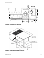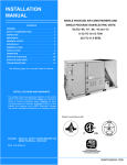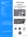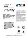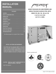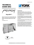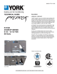
1
036-21551-001-B-0305
®
TECHNICAL
GUIDE
®
DESCRIPTION
ASHRAE 90.1 COMPLIANT
MagnaDRY™
SINGLE PACKAGE AIR CONDITIONERS
AND SINGLE PACKAGE GAS/ELECTRIC
UNITS
DR090, 120 and 150
YORK® Predator® MagnaDry™ units are convertible single
packages with a common footprint cabinet and common roof
curb for all 7-1/2 through 12-1/2 ton models. All units have
two compressors with independent refrigeration circuits to
provide 2 stages of cooling. The units were designed for light
commercial applications and can be easily installed on a roof
curb, slab, or frame.
All Predator® MagnaDry™ units are self-contained and
assembled on rigid full perimeter base rails allowing for 3-way
forklift access and overhead rigging. Every unit is completely
charged, wired, piped, and tested at the factory to provide a
quick and easy field installation.
All units are convertible between side and down airflow. Independent economizer designs are used on side and down discharge applications, as well as all tonnage sizes.
Predator® MagnaDry™ units are available in the following
configurations: cooling only, cooling with electric heat, and
cooling with gas heat. Electric heaters are available as factory-installed options or field-installed accessories.
DR090, 120
The Predator® MagnaDry™ provides energy-savings, efficient removal of moisture through a balanced coil design.
Because the unit doesn’t increase sensible cooling, it allows
temperatures to be maintained within the comfort zone.
Unlike competitive systems, you’re not subjected to over
cooling. You save through more efficient matching of dehumidification and cooling needs. This makes the MagnaDry™
perfect for applications that need to remove large amounts of
moisture or maintain low humidity levels.
Tested in accordance with:
DR150
FOR DISTRIBUTION USE ONLY - NOT TO BE USED AT POINT OF RETAIL SALE
036-21551-001-B-0305
TABLE OF CONTENTS
DESCRIPTION . . . . . . . . . . . . . . . . . . . . . . . . . . . . . . . . . . . . . 1
29 TYPICAL LOW VOLTAGE FIELD WIRING . . . . . . . . . . . 53
FEATURES . . . . . . . . . . . . . . . . . . . . . . . . . . . . . . . . . . . . . . . . 5
30 FIELD WIRING DISCONNECT-COOLING UNIT WITH/
WITHOUT ELECTRIC HEAT . . . . . . . . . . . . . . . . . . . . . . 54
FACTORY INSTALLED OPTIONS . . . . . . . . . . . . . . . . . . . . . 7
FIELD INSTALLED ACCESSORIES . . . . . . . . . . . . . . . . . . . 8
REHEAT MODE SEQUENCE OF OPERATION . . . . . . . . . . 9
NOMENCLATURE . . . . . . . . . . . . . . . . . . . . . . . . . . . . . . . . . 14
NOMENCLATURE ADDITIONAL OPTIONS: . . . . . . . . . . . 15
31 FIELD WIRING DISCONNECT-COOLING UNIT
WITH GAS HEAT . . . . . . . . . . . . . . . . . . . . . . . . . . . . . . . 54
32 DR090, 120 COOLING UNIT WITH GAS
HEAT WIRING 230 VOLT DIAGRAM . . . . . . . . . . . . . . . 55
GUIDE SPECIFICATIONS . . . . . . . . . . . . . . . . . . . . . . . . . . 63
33 DR150 COOLING UNIT WITH GAS
HEAT WIRING 230 VOLT DIAGRAM . . . . . . . . . . . . . . . 56
LIST OF FIGURES
34 DR090, 120 COOLING UNIT WITH/WITHOUT
ELECTRIC HEAT WIRING DIAGRAM . . . . . . . . . . . . . . . 57
Fig. #
Pg. #
1 PREDATOR® MAGNADRY™ DR090, 120 . . . . . . . . . . . . 4
2 PREDATOR® MAGNADRY™ DR150 . . . . . . . . . . . . . . . . 5
3 REHEAT CONTROL BOARD . . . . . . . . . . . . . . . . . . . . . . 10
35 DR150 COOLING UNIT WITH/WITHOUT
ELECTRIC HEAT WIRING DIAGRAM . . . . . . . . . . . . . . . 58
36 DR090, 120 COOLING UNIT WITH GAS HEAT
WIRING 460, 575 VOLT 50 HZ DIAGRAM . . . . . . . . . . . 59
4 DR090 & 120 REHEAT CONTROLS . . . . . . . . . . . . . . . . 11
37 DR150 COOLING UNIT WITH GAS HEAT WIRING
460, 575 & 50 HZ DIAGRAM . . . . . . . . . . . . . . . . . . . . . . 60
5 DR150 REHEAT CONTROLS. . . . . . . . . . . . . . . . . . . . . . 12
38 DR090 AND 120 REHEAT WIRING DIAGRAM . . . . . . . . 61
6 DR090 MOISTURE REMOVAL - ALTERNATE MODE . . 26
39 DR150 REHEAT WIRING DIAGRAM . . . . . . . . . . . . . . . . 62
7 DR090 MOISTURE REMOVAL - NORMAL MODE . . . . . 26
LIST OF TABLES
8 DR120 MOISTURE REMOVAL - ALTERNATE MODE . . 27
9 DR120 MOISTURE REMOVAL - NORMAL MODE . . . . . 27
Tbl. #
Pg. #
10 DR150 MOISTURE REMOVAL - ALTERNATE MODE . . 28
1 ACCESSORIES . . . . . . . . . . . . . . . . . . . . . . . . . . . . . . . . 13
11 DR150 MOISTURE REMOVAL - NORMAL MODE . . . . . 28
2 PHYSICAL DATA . . . . . . . . . . . . . . . . . . . . . . . . . . . . . . . 18
12 DOWNFLOW APPLICATION POWER
EXHAUST ACCESSORY . . . . . . . . . . . . . . . . . . . . . . . . . 45
3 DR CAPACITY RATINGS. . . . . . . . . . . . . . . . . . . . . . . . . 19
4 UNIT VOLTAGE LIMITATIONS . . . . . . . . . . . . . . . . . . . . 19
13 HORIZONTAL APPLICATION POWER
EXHAUST ACCESSORY . . . . . . . . . . . . . . . . . . . . . . . . . 45
5 COOLING CAPACITY DR090 UNIT . . . . . . . . . . . . . . . . 20
14 DR090, 120 UNITS 4 POINT LOAD . . . . . . . . . . . . . . . . . 46
6 COOLING CAPACITY DR090 UNIT
(ALTERNATE REHEAT MODE) . . . . . . . . . . . . . . . . . . . . 21
15 DR090, 120 UNITS 6 POINT LOAD . . . . . . . . . . . . . . . . . 46
7 COOLING CAPACITY DR120 UNIT . . . . . . . . . . . . . . . . 22
16 UNIT CENTER OF GRAVITY DR090, 120 . . . . . . . . . . . . 46
17 DR150 UNIT 4 POINT LOAD . . . . . . . . . . . . . . . . . . . . . . 46
18 DR150 UNIT 6 POINT LOAD . . . . . . . . . . . . . . . . . . . . . . 46
19 UNIT CENTER OF GRAVITY DR150 . . . . . . . . . . . . . . . . 46
20 DR090/120 UNIT DIMENSIONS . . . . . . . . . . . . . . . . . . . . 47
21 DR150 UNIT DIMENSIONS . . . . . . . . . . . . . . . . . . . . . . . 48
8 COOLING CAPACITY DR120 UNIT
(ALTERNATE REHEAT MODE) . . . . . . . . . . . . . . . . . . . . 23
9 COOLING CAPACITY DR150 UNIT . . . . . . . . . . . . . . . . 24
10 COOLING CAPACITY DR150 UNIT
(ALTERNATE REHEAT MODE) . . . . . . . . . . . . . . . . . . . . 25
22 PREDATOR® ROOF CURB DIMENSIONS . . . . . . . . . . . 49
11 ELECTRICAL DATA DR090 W/O PWRD
CONVENIENCE OUTLET . . . . . . . . . . . . . . . . . . . . . . . . 29
23 SUNLINE™ TO PREDATOR® TRANSITION
ROOF CURBS . . . . . . . . . . . . . . . . . . . . . . . . . . . . . . . . . . 49
12 ELECTRICAL DATA DR090 WITH PWRD
CONVENIENCE OUTLET . . . . . . . . . . . . . . . . . . . . . . . . 29
24 BOTTOM DUCT OPENINGS (FROM ABOVE) . . . . . . . . 50
13 ELECTRICAL DATA DR120 W/O PWRD
CONVENIENCE OUTLET . . . . . . . . . . . . . . . . . . . . . . . . 30
25 DR090, 120 REAR DUCT DIMENSIONS . . . . . . . . . . . . . 50
26 DR150 REAR DUCT DIMENSIONS . . . . . . . . . . . . . . . . . 51
27 DOWNFLOW ECONOMIZER HOOD DETAIL . . . . . . . . . 51
28 DOWNFLOW ECONOMIZER HOOD DETAIL . . . . . . . . . 52
2
14 ELECTRICAL DATA DR120 WITH PWRD
CONVENIENCE OUTLET . . . . . . . . . . . . . . . . . . . . . . . . 30
15 ELECTRICAL DATA DR150 W/O PWRD
CONVENIENCE OUTLET . . . . . . . . . . . . . . . . . . . . . . . . 31
Unitary Products Group
036-21551-001-B-0305
16 ELECTRICAL DATA DR150 W/PWRD
CONVENIENCE OUTLET . . . . . . . . . . . . . . . . . . . . . . . . . 31
26 BLOWER PERFORMANCE DR150 SIDEFLOW . . . . . . . 40
17 ELECTRIC HEAT MULTIPLIERS . . . . . . . . . . . . . . . . . . . 31
27 BLOWER PERFORMANCE DR150
SIDEFLOW ECONOMIZER . . . . . . . . . . . . . . . . . . . . . . . 41
18 BLOWER PERFORMANCE DR090 SIDEFLOW . . . . . . . 32
28 BLOWER PERFORMANCE DR150 DOWNFLOW . . . . . 42
19 BLOWER PERFORMANCE DR090
SIDEFLOW ECONOMIZER . . . . . . . . . . . . . . . . . . . . . . . . 33
29 BLOWER PERFORMANCE DR150
DOWNFLOW ECONOMIZER . . . . . . . . . . . . . . . . . . . . . . 43
20 BLOWER PERFORMANCE DR090 DOWNFLOW . . . . . . 34
30 ADDITIONAL STATIC RESISTANCE . . . . . . . . . . . . . . . . 44
21 BLOWER PERFORMANCE DR090
DOWNFLOW ECONOMIZER . . . . . . . . . . . . . . . . . . . . . . 35
31 ELECTRIC HEAT MINIMUM SUPPLY AIR CFM . . . . . . . 44
22 BLOWER PERFORMANCE DR120 SIDEFLOW . . . . . . . 36
23 BLOWER PERFORMANCE DR120
SIDEFLOW ECONOMIZER . . . . . . . . . . . . . . . . . . . . . . . . 37
24 BLOWER PERFORMANCE DR120 DOWNFLOW . . . . . . 38
25 BLOWER PERFORMANCE DR120
DOWNFLOW ECONOMIZER . . . . . . . . . . . . . . . . . . . . . . 39
Unitary Products Group
32 INDOOR BLOWER SPECIFICATIONS . . . . . . . . . . . . . . 45
33 POWER EXHAUST SPECIFICATIONS . . . . . . . . . . . . . . 45
34 4 POINT LOAD WEIGHT . . . . . . . . . . . . . . . . . . . . . . . . . 46
35 6 POINT LOAD WEIGHT . . . . . . . . . . . . . . . . . . . . . . . . . 46
36 UNIT WEIGHT . . . . . . . . . . . . . . . . . . . . . . . . . . . . . . . . . . 47
37 UNIT CLEARANCES. . . . . . . . . . . . . . . . . . . . . . . . . . . . . 48
3
036-21551-001-B-0305
Simplicity® control board w/
screw connector for T-stat wiring
and network connections
Disconnect location
(optional disconnect switch)
Filter access (2” throw-away)
Filter drier (solid core)
Terminal block for
hi-voltage connection
Condenser section
Second model
nameplate
inside hinged
access panel
Slide-out motor and
blower assembly fo
easy adjustment
and service
Dual stage
cooling for
maximum
comfort
Belt-drive
blower motor
Power ventor motor
Compressor #2
access (highefficiency compressor w/crankcase heater)
20-gauge aluminized steel tubular
heat exchanger for
long life (stainless
steel option)
Base rails w/forklift
slots (three sides)
and lifting holes
Roof curbs in eight- and fourteeninch heights. Roof curbs for transitioning from York Sunline™ footprint to the DH Series footprints
are also available
(field-installed accessory)
Slide-out drain pan
with steel 3/4” NPT,
female connection
Tool-less door latch
Side entry power
and control wiring
knockouts
Compressor #1 access
(high-efficiency compressor w/crankcase heater)
Two-stage gas
heating to maintain
warm, comfortable
temperature
Intelligent control
board for safe and
efficient operation
FIGURE 1 - PREDATOR® MagnaDRY™ DR090, 120
4
Unitary Products Group
036-21551-001-B-0305
Second model
nameplate inside
hinged access panel
Simplicity™ Control
board w/screw
connectors for T-stat
wiring and Network
Connection
Disconnect
location (optional
disconnect switch)
Filter access
(2" throw-away)
Filter drier (solid core)
Condenser Section
Dual stage cooling
for maximum
comfort
Belt-drive blower
motor
Slide out motor
and blower
assembly for easy
adjustment and
service
Compressor #2
access
(high-efficiency
compressor w/
crankcase heater)
Power ventor
motor
20-gauge
aluminized steel
tubular heat
exchanger for
long life
(stainless steel
option)
Base rails w/
forklift slots
( three sides)
and lifting
holes
Roof curbs in eight-and
fourteen-inch heights.
Roof curbs for
transitioning from York Tool-less door
Sunline TM footprint to
latch
the DM/DH/DJ Series
Side entry power
footprint are available
and control wiring
(field-installed accessory)
knockouts
Slide-out drain pan
with brass ¾" NPT,
female connection
Compressor #1 access
(high-efficiency
compressor w/crankcase
heater)
Two-stage gas heating to
maintain warm,
comfortable temperature
Intelligent control
board for safe and
efficient operation
FIGURE 2 - PREDATOR® MagnaDRY™ DR150
FEATURES
•
•
Service windows have been placed in both condenser
section walls. Rotation of the cover allows easy access
to the condenser coils for cleaning or inspection.
High Efficiency – High efficiency units reach as high as
11.2 EER. Gas/electric units have electronic spark ignition and power vented combustion with steady state efficiencies of 80%. These efficiencies exceed all legislated
minimum levels and provide low operating costs.
Both the unit control board and ignition control board utilize
flash codes to aid in diagnosis of unit malfunctions. Unique
alarm codes quickly identify the source of the unit alarm.
All units use the same standard filter size. This standardization removes any confusion on which filter sizes are
needed for replacement.
Service Friendly – The Predator® incorporates a number of enhancements which improve serviceability.
The motor and blower slide out of the unit as a common
assembly. This facilitates greater access to all the indoor
airflow components, thus simplifying maintenance and
adjustment.
Service time is reduced through the use of hinged, toolless panels. Such panels provide access to frequently
inspected components and areas, including the control
box, compressors, filters, indoor motor & blower, and the
heating section. The panels are screwed in place at the
factory to prevent access by children or other unauthorized persons. It is recommended that the panels be
secured with screws once service is complete.
Unitary Products Group
The non-corrosive drain pan slides out of the unit to permit easy cleaning. The drain pan is accessed by removing the drain pan cover plate on the rear of the unit. Once
the plate is removed, the drain pan slides out through the
rear of the unit.
All Predator® units have a second model nameplate
located inside the control access door. This is to prevent
deterioration of the nameplate through weathering.
•
Environmentally Aware – For improved Indoor Air
Quality, foil faced insulation is used exclusively throughout the units.
5
036-21551-001-B-0305
•
Balanced Heating – The Predator® offers “Ultimate Heating Comfort” with a balance between 1st and 2nd stage
gas heating. The first stage of a gas heat Predator® unit
provides 60% of the heating capacity. Balanced heating
allows the unit to better maintain desired temperatures.
•
Convertible Airflow Design – The side duct openings
are covered when they leave the factory. If a side supply/
return is desired, the installer simply removes the two
side duct covers from the outside of the unit and installs
them over the down shot openings. No panel cutting is
required. Convertible airflow design allows maximum
field flexibility and minimum inventory.
•
System Protection - Suction line freezestats are supplied on all units to protect against loss of charge and coil
frosting when the economizer operates at low outdoor air
temperatures while the compressors are running. Every
unit has solid-core liquid line filter-driers and high and lowpressure switches. Internal compressor protection is standard on all compressors. Crankcase heaters are standard
on reciprocating compressors. Scroll compressors do not
require crankcase heaters. Phase Monitors are standard
on units with scroll compressors. This accessory monitors
the incoming power to the unit and protects the unit from
phase loss and reversed phase rotation.
•
•
On Board Diagnostics - Each alarm will energize a
trouble light on the thermostat, if so equipped, and
flash an alarm code on the control board LED. Each
high and low-pressure switch alarm as well as each
freezestat alarm has its own flash code. The control
board saves the five most recent alarms in memory,
and these alarms can be reviewed at any time.
Alarms and programmed values are retained
through the loss of power.
•
Reliable – From the beginning – All units undergo computer automated testing before they leave the factory.
Units are tested for refrigerant charge and pressure, unit
amperage, and 100% functionality. For the long term –
All Predator® units are painted with a long lasting, powder paint that stands up over the life of the unit. The paint
used has been proven by a 750 hour salt spray test.
•
Flexible Placement – All models and configurations
share the same cabinet/footprint and thus the same roof
curb. You have the flexibility to set one curb and choose
the correct tonnage size and heating option after the
internal loads have been determined.
To further simplify planning and installation, Predator®
cabinets are designed to fit your roof. With the optional
roof curb, the unit ductwork is designed to fit around 24”
on-center joists or between 48” on-center joists.
Advanced Controls - Simplicity® control boards have
standardized a number of features previously available
only as options or by utilizing additional controls.
•
Low Ambient - An integrated low-ambient control
allows all units to operate in the cooling mode down
to 0°F outdoor ambient without additional assistance. Optionally, the control board can be programmed to lockout the compressors when the
outdoor air temperature is low or when free cooling
is available.
•
•
Anti-Short Cycle Protection - To aid compressor
life, an anti-short cycle delay is incorporated into the
standard controls. Compressor reliability is further
ensured by programmable minimum run times. For
testing, the anti-short cycle delay can be temporarily
overridden with the push of a button.
Full Perimeter Base Rails – The permanently attached
base rails provide a solid foundation for the entire unit
and protect the unit during shipment. The rails offer forklift access from 3 sides, and rigging holes are available
so that an overhead crane can be used to place the units
on a roof.
•
•
Fan Delays - Fan on and fan off delays are fully programmable. Furthermore, the heating and cooling
fan delay times are independent of one another. All
units are programmed with default values based
upon their configuration of cooling and heat.
Easy Installation – Gas and electric utility knockouts are
supplied in the unit underside as well as the side of the
unit. A clearly identified location is provided to mount a
field supplied electrical disconnect switch. Utility connections can be made quickly and with a minimum amount
of field labor.
•
Safety Monitoring - The control board monitors the
high and low-pressure switches, the freezestats, the
gas valve, if applicable, and the temperature limit
switch on gas and electric heat units. The unit control board will alarm on ignition failures, compressor
lockouts and repeated limit switch trips.
•
6
three times within two hours before the unit control
board will lock out the associated compressor.
Nuisance Trip Protection and Strikes - To prevent
nuisance trouble calls, the control board uses a
“three times, you’re out” philosophy. The high and
low-pressure switches and the freezestats must trip
The drain pan can be rotated to drain to either the front
or the rear of the unit. Additionally, the drain pan can be
fitted to drain through the roof curb. As it is sometimes
difficult to have a level installation, the drain pan features
a generous slope to ensure proper drainage.
All units are shipped with 2” throw-away filters installed.
•
Wide Range of Indoor Airflows – All indoor fan motors
are belt-drive type providing maximum flexibility to handle most airflow requirements. For high static applications, factory installed alternate indoor fan motors are
available. With the optional indoor fan motor, all units can
supply nominal airflow at a minimum of 1.5” ESP.
•
Warranty - All models include a 1-year limited warranty
on the complete unit. Compressors and electric heater
elements each carry a 5-year warranty. Aluminized steel
Unitary Products Group
036-21551-001-B-0305
and stainless steel tubular heat exchangers carry a 10year warranty.
door air dampers open to the preset position when the
indoor fan motor is energized. The damper has a range
of 0% to 100% outdoor air entry. Factory installed option
or field installed accessory.
FACTORY INSTALLED OPTIONS
YORK® offers several equipment options factory installed, for
the Predator® line.
•
Downflow Economizer - (With barometric relief) - The
economizer is provided with a single enthalpy input. The
economizer is 2% low leakage type, and is shipped
installed and wired. The installer needs only to assemble
and mount the outdoor air hood (Provided). The economizer has spring return, fully modulating damper actuators
and is capable of introducing up to 100% outdoor air. As
the outdoor air intake dampers open, the return air dampers close. The changeover from mechanical refrigeration
to economizer operation is regulated by the standard single enthalpy input. There is an optional input dual dry bulb
available. To meet regulated air standards, the economizer
control accepts an optional CO2 input for demand ventilation. With single enthalpy input, the economizer control
monitors outdoor air. The dual enthalpy kit provides a second input used to monitor the return air. With a dual input
kit installed, the economizer control compares the values
of the two enthalpy or temperature inputs and positions the
dampers to provide the maximum efficiency possible.
•
Horizontal Economizer - (Without barometric relief) All features of the downflow economizer exist except you
must order the duct mount barometric relief separately.
You must order a 1EH0408 if you are installing a
power exhaust. You can order a 1RD0411 Barometric
Relief for horizontal flow economizers only.
•
Slab Economizer for Energy Recovery Ventilators(With barometric relief and Fresh Air Hood) - The
economizer is provided with a single enthalpy input. The
economizer is 2% low leakage type, and is shipped
installed and wired. The economizer has spring return,
fully modulating damper actuators and is capable of introducing up to 100% outdoor air. As the outdoor air intake
dampers open, the return air dampers close. The
changeover from mechanical refrigeration to economizer
operation is regulated by the standard single enthalpy
input. There is an optional input dual dry bulb available. To
meet regulated air standards, the economizer control
accepts an optional CO2 input for demand ventilation.With
single enthalpy input, the economizer control monitors
outdoor air. The dual enthalpy kit provides a second input
used to monitor the return air. With a dual input kit
installed, the economizer control compares the values of
the two enthalpy or temperature inputs and positions the
dampers to provide the maximum efficiency possible.
•
Power Exhaust (Downflow only) - This accessory
installs in the unit with a down flow economizer.
•
Motorized Outdoor Air Damper - The motorized outdoor air damper includes a slide-in/plug-in damper
assembly with an outdoor air hood and filters. The out-
Unitary Products Group
•
Alternate Indoor Blower Motor - For applications with
high static restrictions, units are offered with optional
indoor motors that provide higher static output and/or
higher airflow, depending upon the installer’s needs.
•
Aluminized Steel Gas Heat Exchanger - For applications in non-corrosive environments.
•
Stainless Steel Gas Heat Exchanger - For applications
in corrosive environments, this option provides a full
stainless steel heat exchanger assembly.
•
Stainless Steel Drain Pan - Provides years of trouble
free operation in corrosive environments.
•
Electric Heaters - The electric heaters range from 9kW
to 54kW and are available in all the voltage options of the
base units. All heaters are dual staged. All heaters are
intended for single point power supply.
•
Disconnect Switch - For gas heat units and cooling
units with electric heat, a HACR breaker sized to the unit
is provided. For cooling only units, a switch sized to the
largest electric heat available for the particular unit is
provided. Factory installed option only.
•
Convenience Outlet - (Non-Powered/Powered) - This
option locates a 120V single-phase GFCI outlet with
cover, on the corner of the unit housing adjacent to the
compressors. The “Non-powered” option requires the
installer to provide the 120V single-phase power source
and wiring. The “Powered” option is powered by a stepdown transformer in the unit. Factory installed option only.
•
Smoke Detectors - The smoke detectors stop operation
of the unit by interrupting power to the control board if
smoke is detected within the air compartment. Available
for both the supply and/or return air.
•
Phase Monitors - Designed to prevent unit damage.
The phase monitor will shut the unit down in an out-of
phase condition. (Standard on units with Scroll Compressors.)
•
Coil Guard - Customers can purchase a coil guard kit to
protect the condenser coil from damage. Additionally,
this kit stops animals and foreign objects from entering
the space between the inner condenser coil and the
main cabinet. This is not a hail guard kit.
•
Dirty Filter Switch - This kit includes a differential pressure switch that energizes the fault light on the unit thermostat, indicating that there is an abnormally high
pressure drop across the filters. Factory installed option
or field installed accessory.
•
Technicoat Condenser Coils - The condenser coils are
coated with a phenolic coating for protection against corrosion due to harsh environments.
7
036-21551-001-B-0305
•
•
Technicoat Evaporator Coil - The evaporator coils are
coated with a phenolic coating for protection against corrosion due to harsh environments.
BAS - Building Automation System Controls
Simplicity® Intelli-Comfort™ Control - The York
Simplicity® Intelli-Comfort™ control is factory installed. It
includes a supply air sensor, a return air sensor, and an
outside air sensor. There are provisions for a field
installed dirty filter indicator switch, an air-proving switch,
an Outside Air Humidity sensor, a Return Air Humidity
sensor, an Inside IAQ sensor, and an Outside Air IAQ
sensor. Construction mode operation, 365-day real time
clock with 7 day programming plus holiday scheduling is
built-in. Two different modes of demand ventilation are
achieved through the Intelli-Comfort™ using CO2
sensors. It uses an inside CO2 sensor to perform
Demand Ventilation. It can also use an Outside CO2
sensor to perform Differential Demand Ventilation. It
uses a Patented Comfort Ventilation algorithm to provide
comfortable ventilation air temperature. The patented
economizer-loading algorithm will protect the equipment
when harsh operating conditions exist. Humidity in the
occupied space or return duct can be monitored and
controlled via humidity sensors and the on-board
connection for hot gas re-heat system. It uses the
Intelli-Start algorithm to maximize energy savings by
recovering the building from the Unoccupied Setpoints to
the Occupied Setpoints just in time for the Occupied
Time Period to begin. The Simplicity® Intelli-Comfort™
balances space temperature, ventilation air temperature,
CO2 and humidity for ultimate comfort.
•
Simplicity® Intelli-Comfort™ with ModLINC Control The York Simplicity® Intelli-Comfort™ with ModLINC
control is factory installed. It includes all the features of
the Intelli-Comfort™ control with an additional control to
translate communications from MODBUS to the BACnet
MSTP protocol.
•
Novar® BAS Control - The Novar® ETC-3 building
automation system controller is factory installed. Incudes
supply air sensor, return air sensor, dirty filter indicator
switch, and air proving switch.
•
Johnson Controls BAS Control - The Johnson Control
YK-UNT-1126 building automation system controller is
factory installed. Includes supply air sensor, return air
sensor, dirty filter indicator switch, and air proving switch.
•
CPC BAS Control - The Computer Process Controls
Model 810-3060 ARTC Advanced Rooftop building automation system controller is factory installed. Includes
supply air sensor, return air sensor, dirty filter indicator
switch and air proving switch.
•
8
Honeywell BAS Control - The Honeywell W7750C
building automation system controller is factory installed.
Includes air supply sensor, return air sensor, dirty filter
indicator switch, and air proving switch.
FIELD INSTALLED ACCESSORIES
YORK® offers several equipment accessories for field installation, for the Predator® line.
•
Downflow Economizer - (With barometric relief) - The
economizer is provided with a single enthalpy input. The
economizer is 2% low leakage type. The economizer has
spring return, fully modulating damper actuators and is
capable of introducing up to 100% outdoor air. As the outdoor air intake dampers open, the return air dampers
close. The changeover from mechanical refrigeration to
economizer operation is regulated by the standard single
enthalpy input. There is an optional input dual dry bulb
available. To meet regulated air standards, the economizer
control accepts an optional CO2 input for demand ventilation. With single enthalpy input, the economizer control
monitors outdoor air. The dual enthalpy kit provides a second input used to monitor the return air. With a dual input
kit installed, the economizer control compares the values
of the two enthalpy or temperature inputs and positions the
dampers to provide the maximum efficiency possible.
•
Horizontal Economizer - (Without barometric relief) All features of the downflow economizer exist except you
must order the duct mount barometric relief separately.
You must order a 1EH0408 if you are installing a
power exhaust. You can order a 1RD0411 Barometric
Relief for horizontal flow economizer.
•
Slab Economizer for Energy Recovery Ventilator(Without barometric relief or Fresh Air Hood) - The
economizer is provided with a single enthalpy input. The
economizer is 2% low leakage type. The economizer has
spring return, fully modulating damper actuators and is
capable of introducing up to 100% outdoor air. As the
outdoor air intake dampers open, the return air dampers
close. The changeover from mechanical refrigeration to
economizer operation is regulated by the standard single
enthalpy input. There is an optional input dual dry bulb
available. To meet regulated air standards, the economizer control accepts an optional CO2 input for demand
ventilation.With single enthalpy input, the economizer
control monitors outdoor air. The dual enthalpy kit provides a second input used to monitor the return air. With
a dual input kit installed, the economizer control compares the values of the two enthalpy or temperature
inputs and positions the dampers to provide the maximum efficiency possible.
You can order 1EH0409 Barometric Relief/FA Hood for
field installations without an ERV.
•
Dual Enthalpy Control, Accessory - This kit contains
the required components to convert a single enthalpy
economizer to dual enthalpy.
•
Barometric Relief Damper - Zero to 100% capacity
barometric relief dampers for use with horizontal flow, or
field installed slab economizers.
•
Power Exhaust - This accessory installs in the unit with
a down flow economizer. Power exhaust plugs into the
Unitary Products Group
036-21551-001-B-0305
connector in the unit bulkhead. You must purchase
1EH0408 barometric relief when applying to a horizontal flow application.
•
Manual Outdoor Air Damper - Like the motorized outdoor air damper, each manual outdoor air damper
includes a slide-in damper assembly with an outdoor air
hood and filters. Customers have a choice of dampers
with ranges of 0% to 100% or 0% to 35% outdoor air
entry.
•
Motorized Outdoor Air Damper - The motorized outdoor air damper includes a slide-in/plug-in damper
assembly with an outdoor air hood and filters. The outdoor air dampers open to the preset position when the
indoor fan motor is energized. The damper has a range
of 0% to 100% outdoor air entry. Factory installed option
or field installed accessory.
•
Smoke Detectors - The smoke detectors stop operation
of the unit by interrupting power to the control board if
smoke is detected within the air compartment.
•
CO2 Sensor - Senses CO2 levels and automatically
overrides the economizer when levels rise above the
preset limits.
•
Dirty Filter Switch - This kit includes a differential pressure switch that energizes the fault light on the unit thermostat, indicating that there is an abnormally high
pressure drop across the filters.
•
Coil Guard - Field installed decorative wire coil guard.
•
Hail Guard - This kit includes a sloped hood which
installs over the outside condenser coil and prevents
damage to the coil fins from hail strikes. Field installed
accessory only.
•
Flue Exhaust Extension Kit - In locations with wind or
weather conditions which may interfere with proper
exhausting of furnace combustion products, this kit can
be installed to prevent the flue exhaust from entering
nearby fresh air intakes.
•
-60°F Gas Heat Kit - For installations which require gas
heat units to perform in low ambient temperatures, a gas
section heating kit is available. This kit provides electric
heat in the gas heat controls section to ensure the gas
valve and controls will continue to function properly at
extremely low temperatures.
•
Gas Heat High Altitude Kit - This kit converts a gas heat
unit to operate at high altitudes, 2,000 to 6,000 feet. Conversion kits are available for natural gas and propane.
•
Gas Heat Propane Conversion Kit - This kit converts a
gas-fired heater from natural gas to propane. It contains
the main burner orifices and gas valve replacement
springs.
•
Gas Piping Kit - Contains pipe nipples, fittings and gas
cock required for gas supply connection with external
shut off.
•
Electric Heaters - The electric heaters range from 9 kW
to 54kW and are available in all the voltage options of the
base units. All heaters are dual staged. Cooling units
include an adapter panel for easy installation of the elec-
Unitary Products Group
tric heaters. Necessary hardware and connectors are
included with the heaters. All heaters are intended for
single point power supply.
•
Low Limit / Compressor Lockout Kit
1. Compressor Lockout (CLO): To prevent mechanical
(compressorized) operation of the unit during cold
outdoor conditions where there is a risk of returning
liquid refrigerant back to the compressors.
2. Low Limit Control (LLC): To prevent the supply air
from dropping below a specified setpoint by utilizing
the units first stage heating means when there is a
demand for cooling during cold outside conditions.
•
Metal Frame Filter Kit - Metal frame with polyester filter
medium.
•
Permanent Filters - Permanent filters are available.
•
Roof Curbs - The roof curbs have insulated decks and
are shipped disassembled The roof curbs are available
in 8” and 14” heights. For applications with security concerns, burglar bars are available for the duct openings of
the roof curbs.
•
Roof Curb Transition - Single Piece Adapter (10” High) Roof curbs for transitioning from Sunline™ units to Predator® units. Fits 7.5 to 12.5 Sunline™ roof curbs only.
•
Burglar Bars - Mount in the supply and return openings
to prevent entry into the duct work.
•
Thermostat - The units are designed to operate with 24volt electronic and electro-mechanical thermostats. All
units (with or without an economizer) operate with twostage heat/two-stage cool or two-stage cooling only thermostats, depending upon unit configuration.
REHEAT MODE SEQUENCE OF OPERATION
The reheat control board allows the user to select two different modes of operation via a jumper connection on the
board. (See Figure 3.) Each mode is described below. Refer
to Figures 3 - 5 when reading this section.
“NORMAL” MODE
When the reheat control board (RCB) detects a need for
dehumidification (24VAC) at "HUM" via the field supplied
dehumidistat connected to RHTB-1 and RHTB-2 and there is
not a call for cooling, it energizes the hot gas relay (HGR),
which energizes the 3-way valve (SOL 3), the condenser coil
valve (SOL 2), and de-energizes the reheat coil bleed valve
(SOL 1). (In the DR150, SOL 2 is only energized when the
discharge pressure in circuit #1 rises above 235 psig and deenergizes SOL 2 after the discharge pressure falls below 175
psig. Both outdoor fans of circuit #1 in the DR150 also disengage to conserve energy.) The Y1 signal is passed to the unit
control board (UCB), which engages circuit # 1, resulting in
circuit #1 reheat mode operation.
When the room thermostat calls for first stage cooling, with or
without a call for dehumidification, the RCB senses a signal
through "Y1", de-energizing the HGR, which de-energizes
SOL 3 and SOL 2 and energizes SOL 1, engaging circuit #1,
resulting in circuit #1 cooling mode operation.
9
036-21551-001-B-0305
When the room thermostat calls for second stage cooling, the
RCB senses a signal through "Y1" & "Y2" and engages circuit
#1 and circuit #2 in cooling mode.
Indoor blower operation is initiated upon a call for first stage
cooling, second stage cooling or dehumidification.
Anytime there is a call for 2 stages of cooling, the unit will not
operate in the reheat mode, even if there is a call for dehumidification at "HUM".
The unit will not operate in the reheat mode if there is any call
for heating.
On units with economizers, the unit will not operate in the
reheat mode if there is a call for cooling and the economizer
is operating as first stage of cooling.
All safety devices function as previously described.
"ALTERNATE” MODE
When the RCB detects a need for dehumidification (24VAC)
at "HUM" via the field supplied dehumidistat connected to
RHTB-1 and RHTB-2, and there is not a call for cooling, it
energizes the HGR, which energizes the SOL 3, SOL 2, and
de-energizes SOL 1. (In the DR150, SOL 2 is only energized
when the discharge pressure in circuit #1 rises above 235
psig and de-energizes SOL 2 after the discharge pressure
falls below 175 psig. Both outdoor fans of circuit #1 in the
DR150 also disengage to conserve energy.) The unit then
operates with circuit #1 in reheat mode and circuit #2 in cooling mode.
When the room thermostat calls for first stage cooling while
there is still a call for dehumidification, no operational change
is made. The call for cooling is ignored and the unit continues
to operate with circuit #1 in reheat mode and circuit #2 in
cooling mode.
When the room thermostat calls for second stage cooling, the
RCB senses a signal through "Y1" and "Y2" and de-energizes the HGR, which de-energizes SOL 3 and SOL 2, and
energizes SOL 1. Both circuits operate in the cooling mode.
Indoor blower operation is initiated upon a call for first stage
cooling, second stage cooling or dehumidification.
Anytime there is a call for 2 stages of cooling, the unit will not
operate in the reheat mode, even if there is still a call for
dehumidification at "HUM".
The unit will not operate in the reheat mode if there is any call
for heating.
All safety devices function as previously described.
R
Y1
P4
Y2
K1
G
W1
K2
W2
OCC
K4
C
K3
COM
`
P6
P5
P3
HGRR
HGR
MODE
SELECTION
JUMPER
HUM
DEHUMIDISTAT
HARNESS
CONNECTION
3
FIGURE 3 - REHEAT CONTROL BOARD
10
Unitary Products Group
036-21551-001-B-0305
FIGURE 4 - DR090 & 120 REHEAT CONTROLS
Unitary Products Group
11
036-21551-001-B-0305
FIGURE 5 - DR150 REHEAT CONTROLS
12
Unitary Products Group
036-21551-001-B-0305
TABLE 1: ACCESSORIES
Part Number
1RC0470
1RC0471
1RC0472
1BD0408
2TP04520925
2TP04521825
2TP04522425
2TP04523625
2TP04525425
2TP04520946
2TP04521846
2TP04522446
2TP04523646
2TP04525446
2TP04520958
2TP04521858
2TP04522458
2TP04523658
2TP04525458
1FA0411
1FA0412
2MD04702724
2MD04703324
2EE04705024
2EE04705124
2EE04705224
2PE04703225
2PE04703246
2PE04703258
2EC04700924
1EH0407
1RD0411
1EH0408
1EH0409
2AQ04700424
2AQ04700324
2SD04700424
2MK04700624
1CG0419
1CG0420
1CG0424
1CG0425
1HG0411
1GP0404
1NP0441
1HA0442
1HA0443
1FE0411
2BC04700106
2BC04700151
2BC04700154
1FL0402
2DF0401
1FF0410
Description
Weight
Roof Curb, 8" Height
Roof Curb, 14" Height
Roof Curb, Transition (7.5 T through 12.5 T)
Burglar Bars, Downflow
Electric Heat 9kW 230V
Electric Heat 18kW 230V
Electric Heat 24kW 230V
Electric Heat 36kW 230V
Electric Heat 54kW 230V
Electric Heat 9kW 460V
Electric Heat 18kW 460V
Electric Heat 24kW 460V
Electric Heat 36kW 460V
Electric Heat 54kW 460V
Electric Heat 9kW 575V
Electric Heat 18kW 575V
Electric Heat 24kW 575V
Electric Heat 36kW 575V
Electric Heat 54kW 575V
Manual Outside Air Damper 0-35%, Downflow (Incl. Hood, Damper & Filters, No Barometric Relief)
Manual Outside Air Damper 0-100%, Downflow (Incl. Hood, Damper & Filters, No Barometric Relief)
Motorized Damper, Downflow (Incl. Hood, Damper & Filter, no Barometric Relief)
Motorized Damper, Horizontal (Incl. Hood, Damper & Filter, no Barometric Relief)
Economizer, Downflow (Incl. Barometric Relief & All Hoods)
Economizer, Horizontal (Incl. Dampers & Hoods, no Barometric Relief)
Economizer, Slab, Downflow (Incl. Dampers only no Hoods or Barometric Relief)
Power Exhaust, Downflow, 230V (For Units with Economizer only)
Power Exhaust, Downflow, 460V(For Units with Economizer only)
Power Exhaust, Downflow, 580V (For Units with Economizer only)
Dual Enthalpy Control (Use with Single Enthalpy Economizer)
Hood Kit, Downflow Economizer (Included with all Downflow Economizers)
Barometric Relief Kit, Ductmount for Horizontal Application (Incl. Damper & Hood)
Barometric Relief Kit, Ductmount for Horizontal Application w/Power Exhaust (Incl. Damper & Hood)
Barometric Relief / Hood Kit, for Field Installed Slab Econ. w/o ERV (Incl. Barometric Relief & FA Hood)
CO2 Detector Unit Mount
CO2 Detector Space Mount
Smoke Detector, Supply or Return (Return Not Available with Horizontal Economizer)
Low Limit / Compressor Lockout Kit
Coil Guard (Electric / Electric & HP models): DR090 & 120
Coil Guard (Gas / Electric models): DR090 & 120
Coil Guard (Electric / Electric & HP models): DR150
Coil Guard (Gas / Electric models): DR150
Hail Guard Kit
Gas Piping Kit
Propane Conversion Kit
High Altitude Kit for Natural Gas
High Altitude Kit for Propane
Flue Exhaust Extension Kit
Gas Heat Kit, -60 deg F, 230V
Gas Heat Kit, -60 deg F, 460V
Gas Heat Kit, -60 deg F, 575V
Permanent Filter Kit
Dirty Filter Switch
Filter Frame Kit, Metal
-
Unitary Products Group
124 lbs.
97 lbs.
-
25 lbs.
-
13
036-21551-001-B-0305
NOMENCLATURE
Predator MagnaDRY™ Model Number Nomenclature
D R 090 N10 A 2 A AA 3
Product Generation
Product Category
3 = Third Generation
4 = Fourth Generation
D = Air Cond., Single Package
Product Identifier
R = R-22 Reheat
Voltage
2 = 208/230-3-60
4 = 460-3-60
5 = 575-3-60
Nominal Cooling Capacity - MBH
090 = 7-1/2 Ton
120 = 10 Ton
150 = 12-1/2 Ton
Heat Type & Nominal Heat Capacity
C00 = Cooling Only. Suitable for field installed electric heat
Gas Heat Options
N 10 = 100 MBH Output Aluminized Steel
N 15 = 150 MBH Output Aluminized Steel
N 20 = 200 MBH Output Aluminized Steel
S 10 = 100 MBH Output Stainless Steel
S 15 = 150 MBH Output Stainless Steel
S 20 = 200 MBH Output Stainless Steel
Installation Options
A = No Options Installed
B = Option 1
C = Option 2
D = Options 1 & 2
E = Option 3
F = Option 4
G = Options 1 & 3
H = Options 1 & 4
J = Options 1, 2 & 3
K = Options 1, 2 & 4
L = Options 1, 3 & 4
M = Options 1, 2, 3 & 4
N = Options 2 & 3
P = Options 2 & 4
Q = Options 2, 3 & 4
R = Options 3 & 4
S = Option 5
T = Options 1 & 5
U = Options 1, 3 & 5
V = Options 1, 4 & 5
W = Options 1, 3, 4 & 5
X = Options 3 & 5
Y = Options 4 & 5
Z = Options 3, 4 & 5
Additional Options
(See Next Page)
Options
Electric Heat Options
1 = Disconnect
2 = Non-Pwr’d Conv Outlet
3 = Smoke Detector S. A.
4 = Smoke Detector R. A.
5 = Pwr’d Conv Outlet
E09 = 9 kW Electric Heat
E18 = 18 kW Electric Heat
E24 = 24 kW Electric Heat
E36 = 36 kW Electric Heat
E54 = 54 kW Electric Heat
Airflow
A = Standard Motor
B = Standard Motor/Economizer/Barometric Relief (Downflow only)
C = Standard Motor/Economizer/Power Exhaust (Downflow only)
D = Standard Motor/Motorized Damper (Downflow only)
E = Standard Motor/Horizontal Economizer (No Barometric Relief)
F = Standard Motor/Slab Economizer/Power Exhaust (Downflow only)
G = Standard Motor/Slab Economizer/Barometric Relief (Downflow only)
L = Standard Motor/BAS Ready Econ (NoBASController)/Barometric Relief w/2" Pleated Filters (Downflow only)
M = Standard Motor/BAS Ready Econ (NoBASController)/Power Exhaust w/2" Pleated Filters (Downflow only)
N = High Static Motor
P = High Static Motor/Economizer/Barometric Relief (Downflow only)
Q = High Static Motor/Economizer/Power Exhaust (Downflow only)
R = High Static Motor/Motorized Damper (Downflow only)
S = High Static Motor/Horizontal Economizer (No Barometric Relief)
T = High Static Motor/Slab Economizer/Power Exhaust (Downflow only)
U =High Static Motor/Slab Economizer/Barometric Relief (Downflow only)
Y = High Static Motor/BAS Ready Econ (NoBASController)/Barometric Relief w/2" Pleated Filters (Downflow only)
Z = High Static Motor/BAS Ready Econ (NoBASController)/Power Exhaust w/2" Pleated Filters (Downflow only)
14
Unitary Products Group
036-21551-001-B-0305
NOMENCLATURE ADDITIONAL OPTIONS:
AA
AB
AC
AD
AE
AF
AG
AH
AJ
AK
AL
AM
AN
CA
CB
CC
CD
CE
CF
CG
CH
CJ
CK
CL
CM
CN
CP
CQ
CR
CS
CT
CU
CV
CW
CX
JA
JB
JC
JD
JE
JF
JG
JH
JJ
JK
JL
JM
JN
JP
JQ
JR
JS
JT
JU
JV
JW
JX
HA
None
Phase Monitor
Coil Guard
Dirty Filter Switch
Phase Monitor & Coil Guard
Phase Monitor & Dirty Filter Switch
Coil Guard & Dirty Filter Switch
Phase Monitor, Coil Guard, & Dirty Filter Switch
SS Drain Pan
SS Drain Pan & Phase Monitor
SS Drain Pan & Coil Guard
SS Drain Pan & Dirty Filter Switch
SS Drain Pan, Phase Monitor, Coil Guard & Dirty Filter Switch
CPC Controller with Dirty Filter Switch & Air Proving Switch
CPC Controller, DFS, APS & Phase Monitor
CPC Controller, DFS, APS & Coil Guard
CPC Controller, DFS, APS, Phase Monitor, & Coil Guard
CPC Controller, DFS, APS & Technicoat Cond. Coil
CPC Controller, DFS, APS, Technicoat Cond. Coil, & Phase Monitor
CPC Controller, DFS, APS, Technicoat Cond. Coil, & Coil Guard
CPC Controller, DFS, APS, Technicoat Cond. Coil, Phase Monitor, & Coil Guard
CPC Controller, DFS, APS & Technicoat Evap. Coil
CPC Controller, DFS, APS, Technicoat Evap. Coil, & Phase Monitor
CPC Controller, DFS, APS, Technicoat Evap. Coil, & Coil Guard
CPC Controller, DFS, APS, Technicoat Evap. Coil, Phase Monitor, & Coil Guard
CPC Controller, DFS, APS & Technicoat Evap. & Cond Coils
CPC Controller, DFS, APS, Technicoat Evap. & Cond Coils, & Phase Monitor
CPC Controller, DFS, APS, Technicoat Evap. & Cond Coils, & Coil Guard
CPC Controller, DFS, APS, Technicoat Evap. & Cond Coils, Phase Monitor, & Coil Guard
CPC Controller, DFS, APS, SS Drain Pan
CPC Controller, DFS, APS, SS Drain Pan, Phase Monitor, & Coil Guard
CPC Controller, DFS, APS, SS Drain Pan, & Technicoat Cond Coils
CPC Controller, DFS, APS, SS Drain Pan, & Technicoat Evap Coil
CPC Controller, DFS, APS, SS Drain Pan, & Technicoat Evap and Cond Coils
CPC Controller, DFS, APS, SS Drain Pan, Phase Monitor, Coil Guard, & Technicoat Evap and Cond Coils
Johnson UNT Controller with Dirty Filter Switch & Air Proving Switch
Johnson UNT Controller, DFS, APS & Phase Monitor
Johnson UNT Controller, DFS, APS & Coil Guard
Johnson UNT Controller, DFS, APS, Phase Monitor, & Coil Guard
Johnson UNT Controller, DFS, APS & Technicoat Cond. Coil
Johnson UNT Controller, DFS, APS, Technicoat Cond. Coil, & Phase Monitor
Johnson UNT Controller, DFS, APS, Technicoat Cond. Coil, & Coil Guard
Johnson UNT Controller, DFS, APS, Technicoat Cond. Coil, Phase Monitor, & Coil Guard
Johnson UNT Controller, DFS, APS & Technicoat Evap. Coil
Johnson UNT Controller, DFS, APS, Technicoat Evap. Coil, & Phase Monitor
Johnson UNT Controller, DFS, APS, Technicoat Evap. Coil, & Coil Guard
Johnson UNT Controller, DFS, APS, Technicoat Evap. Coil, Phase Monitor, & Coil Guard
Johnson UNT Controller, DFS, APS & Technicoat Evap. & Cond Coils
Johnson UNT Controller, DFS, APS, Technicoat Evap. & Cond Coils, & Phase Monitor
Johnson UNT Controller, DFS, APS, Technicoat Evap. & Cond Coils, & Coil Guard
Johnson UNT Controller, DFS, APS, Technicoat Evap. & Cond Coils, Phase Monitor, & Coil Guard
Johnson UNT Controller, DFS, APS, SS Drain Pan
Johnson UNT Controller, DFS, APS, SS Drain Pan, Phase Monitor, & Coil Guard
Johnson UNT Controller, DFS, APS, SS Drain Pan, & Technicoat Cond Coils
Johnson UNT Controller, DFS, APS, SS Drain Pan, & Technicoat Evap Coil
Johnson UNT Controller, DFS, APS, SS Drain Pan, & Technicoat Evap and Cond Coils
Johnson UNT Controller, DFS, APS, SS Drain Pan, Phase Monitor, Coil Guard, & Technicoat Evap and Cond Coils
Honeywell Excel 10 Controller with Dirty Filter Switch & Air Proving Switch
Unitary Products Group
15
036-21551-001-B-0305
HB
HC
HD
HE
HF
HG
HH
HJ
HK
HL
HM
HN
HP
HQ
HR
HS
HT
HU
HV
HW
HX
WA
WB
WC
WD
WE
WF
WG
WH
WJ
WK
WL
WM
WN
WP
WQ
WR
WS
WT
WU
WV
WW
WX
NA
NB
NC
ND
NE
NF
NG
NH
NJ
NK
NL
NM
NN
NP
NQ
NR
16
Honeywell Excel 10 Controller, DFS, APS & Phase Monitor
Honeywell Excel 10 Controller, DFS, APS & Coil Guard
Honeywell Excel 10 Controller, DFS, APS, Phase Monitor, & Coil Guard
Honeywell Excel 10 Controller, DFS, APS & Technicoat Cond. Coil
Honeywell Excel 10 Controller, DFS, APS, Technicoat Cond. Coil, & Phase Monitor
Honeywell Excel 10 Controller, DFS, APS, Technicoat Cond. Coil, & Coil Guard
Honeywell Excel 10 Controller, DFS, APS, Technicoat Cond. Coil, Phase Monitor, & Coil Guard
Honeywell Excel 10 Controller, DFS, APS & Technicoat Evap. Coil
Honeywell Excel 10 Controller, DFS, APS, Technicoat Evap. Coil, & Phase Monitor
Honeywell Excel 10 Controller, DFS, APS, Technicoat Evap. Coil, & Coil Guard
Honeywell Excel 10 Controller, DFS, APS, Technicoat Evap. Coil, Phase Monitor, & Coil Guard
Honeywell Excel 10 Controller, DFS, APS & Technicoat Evap. & Cond Coils
Honeywell Excel 10 Controller, DFS, APS, Technicoat Evap. & Cond Coils, & Phase Monitor
Honeywell Excel 10 Controller, DFS, APS, Technicoat Evap. & Cond Coils, & Coil Guard
Honeywell Excel 10 Controller, DFS, APS, Technicoat Evap. & Cond Coils, Phase Monitor, & Coil Guard
Honeywell Excel 10 Controller, DFS, APS, SS Drain Pan
Honeywell Excel 10 Controller, DFS, APS, SS Drain Pan, Phase Monitor, & Coil Guard
Honeywell Excel 10 Controller, DFS, APS, SS Drain Pan, & Technicoat Cond Coils
Honeywell Excel 10 Controller,DFS, APS, SS Drain Pan, & Technicoat Evap Coil
Honeywell Excel 10 Controller,DFS, APS, SS Drain Pan, & Technicoat Evap and Cond Coils
Honeywell Excel 10 Controller,DFS, APS, SS Drain Pan, Phase Monitor, Coil Guard, & Technicoat Evap and Cond Coils
Intelli-Comfort w/ModLINC Controller with Dirty Filter Switch & Air Proving Switch
Intelli-Comfort w/ModLINC Controller, & Phase Monitor
Intelli-Comfort w/ModLINC Controller, & Coil Guard
Intelli-Comfort w/ModLINC Controller, Phase Monitor, & Coil Guard
Intelli-Comfort w/ModLINC Controller, & Technicoat Cond. Coil
Intelli-Comfort w/ModLINC Controller, Technicoat Cond. Coil, & Phase Monitor
Intelli-Comfort w/ModLINC Controller, Technicoat Cond. Coil, & Coil Guard
Intelli-Comfort w/ModLINC Controller, Technicoat Cond. Coil, Phase Monitor, & Coil Guard
Intelli-Comfort w/ModLINC Controller, & Technicoat Evap. Coil
Intelli-Comfort w/ModLINC Controller, Technicoat Evap. Coil, & Phase Monitor
Intelli-Comfort w/ModLINC Controller, Technicoat Evap. Coil, & Coil Guard
Intelli-Comfort w/ModLINC Controller, Technicoat Evap. Coil, Phase Monitor, & Coil Guard
Intelli-Comfort w/ModLINC Controller, & Technicoat Evap. & Cond Coils
Intelli-Comfort w/ModLINC Controller, Technicoat Evap. & Cond Coils, & Phase Monitor
Intelli-Comfort w/ModLINC Controller, Technicoat Evap. & Cond Coils, & Coil Guard
Intelli-Comfort w/ModLINC Controller, Technicoat Evap. & Cond Coils, Phase Monitor, & Coil Guard
Intelli-Comfort w/ModLINC Controller, SS Drain Pan
Intelli-Comfort w/ModLINC Controller, SS Drain Pan, Phase Monitor, & Coil Guard
Intelli-Comfort w/ModLINC Controller, SS Drain Pan, & Technicoat Cond Coils
Intelli-Comfort w/ModLINC Controller, SS Drain Pan, & Technicoat Evap Coil
Intelli-Comfort w/ModLINC Controller, SS Drain Pan, & Technicoat Evap and Cond Coils
Intelli-Comfort w/ModLINC Controller, SS Drain Pan, Phase Monitor, Coil Guard, & Technicoat Evap and Cond Coils
Novar ETC-3 Controller with Dirty Filter Switch & Air Proving Switch
Novar ETC-3 Controller, DFS, APS & Phase Monitor
Novar ETC-3 Controller, DFS, APS & Coil Guard
Novar ETC-3 Controller, DFS, APS, Phase Monitor, & Coil Guard
Novar ETC-3 Controller, DFS, APS & Technicoat Cond. Coil
Novar ETC-3 Controller, DFS, APS, Technicoat Cond. Coil, & Phase Monitor
Novar ETC-3 Controller, DFS, APS, Technicoat Cond. Coil, & Coil Guard
Novar ETC-3 Controller, DFS, APS, Technicoat Cond. Coil, Phase Monitor, & Coil Guard
Novar ETC-3 Controller, DFS, APS & Technicoat Evap. Coil
Novar ETC-3 Controller, DFS, APS, Technicoat Evap. Coil, & Phase Monitor
Novar ETC-3 Controller, DFS, APS, Technicoat Evap. Coil, & Coil Guard
Novar ETC-3 Controller, DFS, APS, Technicoat Evap. Coil, Phase Monitor, & Coil Guard
Novar ETC-3 Controller, DFS, APS & Technicoat Evap. & Cond Coils
Novar ETC-3 Controller, DFS, APS, Technicoat Evap. & Cond Coils, & Phase Monitor
Novar ETC-3 Controller, DFS, APS, Technicoat Evap. & Cond Coils, & Coil Guard
Novar ETC-3 Controller, DFS, APS, Technicoat Evap. & Cond Coils, Phase Monitor, & Coil Guard
Unitary Products Group
036-21551-001-B-0305
NS
NT
NU
NV
NW
NX
LA
LB
LC
LD
LE
LF
LG
LH
LJ
LK
LL
LM
LN
LP
LQ
LR
LS
LT
LU
LV
LW
LX
TA
TB
TC
TD
TE
TF
TG
TH
TJ
TK
TL
TM
TN
TP
TQ
TR
TS
TT
TU
TV
TW
TX
TY
TZ
T1
T3
T4
T6
T7
T9
Novar ETC-3 Controller, DFS, APS, SS Drain Pan
Novar ETC-3 Controller, DFS, APS, SS Drain Pan, Phase Monitor, & Coil Guard
Novar ETC-3 Controller, DFS, APS, SS Drain Pan, & Technicoat Cond Coils
Novar ETC-3 Controller, DFS, APS, SS Drain Pan, & Technicoat Evap Coil
Novar ETC-3, DFS, APS, SS Drain Pan, & Technicoat Evap and Cond Coils
Novar ETC-3 Controller, DFS, APS, SS Drain Pan, Phase Monitor, Coil Guard, & Technicoat Evap and Cond Coils
Simplicity Intelli-Comfort Controller
Simplicity Intelli-Comfort Controller, & Phase Monitor
Simplicity Intelli-Comfort Controller, & Coil Guard
Simplicity Intelli-Comfort Controller, Phase Monitor, & Coil Guard
Simplicity Intelli-Comfort Controller, & Technicoat Cond. Coil
Simplicity Intelli-Comfort Controller, Technicoat Cond. Coil, & Phase Monitor
Simplicity Intelli-Comfort Controller, Technicoat Cond. Coil, & Coil Guard
Simplicity Intelli-Comfort Controller, Technicoat Cond. Coil, Phase Monitor, & Coil Guard
Simplicity Intelli-Comfort Controller, & Technicoat Evap. Coil
Simplicity Intelli-Comfort Controller, Technicoat Evap. Coil, & Phase Monitor
Simplicity Intelli-Comfort Controller, Technicoat Evap. Coil, & Coil Guard
Simplicity Intelli-Comfort Controller, Technicoat Evap. Coil, Phase Monitor, & Coil Guard
Simplicity Intelli-Comfort Controller, & Technicoat Evap. & Cond Coils
Simplicity Intelli-Comfort Controller, Technicoat Evap. & Cond Coils, & Phase Monitor
Simplicity Intelli-Comfort Controller, Technicoat Evap. & Cond Coils, & Coil Guard
Simplicity Intelli-Comfort Controller, Technicoat Evap. & Cond Coils, Phase Monitor, & Coil Guard
Simplicity Intelli-Comfort Controller, SS Drain Pan
Simplicity Intelli-Comfort Controller, SS Drain Pan, Phase Monitor, & Coil Guard
Simplicity Intelli-Comfort Controller, SS Drain Pan, & Technicoat Cond Coils
Simplicity Intelli-Comfort Controller, SS Drain Pan, & Technicoat Evap Coil
Simplicity Intelli-Comfort Controller, SS Drain Pan, & Technicoat Evap and Cond Coils
Simplicity Intelli-Comfort Controller, SS Drain Pan, Phase Monitor, Coil Guard, & Technicoat Evap and Cond Coils
Technicoat Condenser Coil
Technicoat Condenser Coil & Phase Monitor
Technicoat Condenser Coil & Coil Guard
Technicoat Condenser Coil & Dirty Filter Switch
Technicoat Condenser Coil, Phase Monitor, & Coil Guard
Technicoat Condenser Coil, Phase Monitor, & Dirty Filter Switch
Technicoat Condenser Coil, Coil Guard, & Dirty Filter Switch
Technicoat Condenser Coil, Phase Monitor, Coil Guard, & Dirty Filter Switch
Technicoat Evaporator Coil
Technicoat Evaporator Coil & Phase Monitor
Technicoat Evaporator Coil & Coil Guard
Technicoat Evaporator Coil & Dirty Filter Switch
Technicoat Evaporator Coil, Phase Monitor, & Coil Guard
Technicoat Evaporator Coil, Phase Monitor, & Dirty Filter Switch
Technicoat Evaporator Coil, Coil Guard, & Dirty Filter Switch
Technicoat Evaporator Coil, Phase Monitor, Coil Guard, & Dirty Filter Switch
Technicoat Evaporator & Condenser Coils
Technicoat Evaporator & Condenser Coils & Phase Monitor
Technicoat Evaporator & Condenser Coils & Coil Guard
Technicoat Evaporator & Condenser Coils & Dirty Filter Switch
Technicoat Evaporator & Condenser Coils, Phase Monitor, & Coil Guard
Technicoat Evaporator & Condenser Coils, Phase Monitor, & Dirty Filter Switch
Technicoat Evaporator & Condenser Coils, Coil Guard, & Dirty Filter Switch
Technicoat Evaporator & Condenser Coils, Phase Monitor, Coil Guard, & Dirty Filter Switch
Technicoat Condenser & SS Drain Pan
Technicoat Condenser Coil, SS Drain Pan, Phase Monitor, Coil Guard, & Dirty Filter Switch
Technicoat Evaporator & SS Drain Pan
Technicoat Evaporator Coil, SS Drain Pan, Phase Monitor, Coil Guard, & Dirty Filter Switch
Technicoat Evaporator & Condenser Coils & SS Drain Pan
Technicoat Evaporator & Condenser Coils, SS Drain Pan, Phase Monitor, Coil Guard, & Dirty Filter Switch
Unitary Products Group
17
036-21551-001-B-0305
TABLE 2: PHYSICAL DATA
Component
Evaporator
Blower
Evaporator Coil
Reheat Coil
Condenser Fan
Condenser Coil
Refrigerant
Charge
Compressors
Air Filters
18
Blower, Centrifugal (Dia. X Wd. In.)
Motor, Standard (HP)
Motor, Optional (HP)
Rows
Fins per Inch
Height (in.)
Face Area (ft.2)
Rows
Fins per Inch
Height (in.)
Face Area (ft.2)
Quantity
Propeller Dia. (in., each)
Motor (HP, each)
CFM, Nominal (each)
Number of Coils
Rows (each)
Fins per Inch
Height (in., each)
Face Area (ft.2 each)
System 1 (lb./oz.)
System 2 (lb./oz.)
Quantity
Type
Size (Wd. X Ht. X Thickness in.)
Quantity
Models
90
120
150
15 x 15
1-1/2
2
3
15
32
10.6
2
13
28
7.8
2
24
1/3
3400
2
1
20
44
14.5
8/0
6/6
2
Recip.
25 x 20 x 2
4
15 x 15
2
3
4
15
40
13.2
2
13
36
10
2
24
3/4
4400
2
2
20
44
14.5
12/12
10/2
2
Recip.
25 x 20 x 2
4
15 x 15
3
5
4
15
40
13.2
2
13
36
10
4
24
1/3
3500
4
2
15
36
11.9
22/8
21/4
2
Scroll
25 x 20 x 2
4
Unitary Products Group
036-21551-001-B-0305
TABLE 3: DR CAPACITY RATINGS
Cooling Capacity
ARI Ratings1
Size
Nominal
Electric
Heat
Capacity3
(kW)
Input
(MBH)
Output
(MBH)
Seasonal
Efficiency
(%)
Temp.
Rise
(°F)
-
-
-
-
-
-
9, 18, 24,
36
-
-
-
-
-
Gas Heat
-
120
96
80
15-45
3/4
Gas Heat
-
180
144
80
30-60
3/4
Cooling
Only
-
-
-
-
-
-
18, 24, 36,
54
-
-
-
-
-
Gas Heat
-
180
144
80
20-50
3/4
Gas Heat
-
240
192
80
35-65
3/4
Cooling
Only
-
-
-
-
-
-
18, 24, 36,
54
-
-
-
-
-
Gas Heat
-
180
144
80
10-40
3/4
Gas Heat
-
240
192
80
25-55
3/4
Model
CFM
MBH
EER
IPLV
Sound
Rating
(dB)2
Cooling
Only
090
120
150
Electric
Heat
Electric
Heat
Electric
Heat
90
116
148
11.2
11.2
11.1
11.65
11.40
11.7
3000
3480
3750
84
90
86
1.
Rated at 95°F ambient 80°F dry bulb and 67°F wet bulb.
2.
Rated in accordance with ARI 270 standard.
3.
See Table 15.
Gas Heat Capacity
Gas
Line
Size
(in. OD)
TABLE 4: UNIT VOLTAGE LIMITATIONS
POWER RATING
MIN.
MAX.
208/230-3-60
187
252
460-3-60
432
504
575-3-60
540
630
Unitary Products Group
19
036-21551-001-B-0305
TABLE 5: COOLING CAPACITY DR090 UNIT
Air On
Evap. Coil
Temperature of Air on Condenser Coil 85°F
Temperature of Air on Condenser Coil 95°F
CFM
WB (°F)
86
Sensible Capacity (MBH)
Return Dry Bulb (°F)
83
80
77
74
71
68
Total
Cap.*
(MBH)
105
6.7
60
54
47
41
35
28
22
96
7.3
2250
72
67
62
57
94
6.5
73
67
61
54
48
41
35
87
85
82
6.3
6.3
85
82
79
82
72
75
66
69
60
62
53
56
47
50
109
6.8
67
59
51
44
36
29
2625
72
67
62
57
97
6.6
81
73
66
58
50
43
88
85
6.4
6.4
88
85
85
85
78
82
71
74
63
66
113
6.9
73
64
55
47
3000
72
67
62
57
101
6.8
88
79
71
62
90
88
6.6
6.6
90
88
90
88
84
88
72
67
62
57
115
7.0
79
69
3375
103
6.8
95
85
92
90
6.6
6.6
92
90
92
90
72
67
62
57
118
7.0
85
74
62
51
40
3750
105
6.8
102
91
80
69
57
94
92
6.6
6.6
94
92
94
92
94
92
83
81
72
69
88
7.8
55
48
42
35
2250
72
67
62
57
79
7.6
67
61
54
72
72
7.4
7.4
72
72
70
71
91
7.9
61
2625
72
67
62
57
82
7.6
74
74
75
7.4
7.4
72
67
62
57
95
3000
85
3375
Total
Cap.*
(MBH)
Tot.
Input†
(kW)
Tot.
Input†
(kW)
86
Sensible Capacity (MBH)
Return Dry Bulb (°F)
83
80
77
74
71
68
57
50
44
38
31
25
18
7.1
70
64
57
51
45
38
32
78
78
6.9
6.9
78
78
74
76
68
70
62
63
55
57
49
50
42
44
21
100
7.4
63
56
48
40
33
25
18
35
90
7.2
78
70
63
55
48
40
32
56
59
48
51
81
81
7.0
7.0
81
81
79
80
74
76
67
68
59
61
51
53
44
46
38
29
20
104
7.5
70
61
52
43
35
26
17
53
44
36
93
7.3
85
77
68
59
50
42
33
76
79
67
70
58
62
49
53
84
84
7.1
7.0
84
84
84
84
80
82
72
74
63
65
54
56
45
47
59
49
39
29
19
105
7.5
75
65
55
45
35
25
15
75
65
55
45
35
94
7.3
90
82
72
62
52
42
32
89
90
79
80
70
70
60
60
50
50
85
85
7.1
7.1
85
85
85
85
83
84
73
74
63
64
54
54
44
44
29
18
106
7.6
80
69
58
47
36
25
13
46
35
96
7.3
96
87
76
65
53
42
31
61
58
50
47
86
86
7.1
7.1
86
86
86
86
86
86
75
74
64
63
53
52
42
41
29
23
16
81
8.3
52
46
40
33
27
20
14
48
41
35
28
71
8.0
64
57
51
44
38
31
25
63
64
57
58
50
51
44
45
38
39
65
66
7.8
7.8
65
66
65
65
58
59
52
52
46
46
39
40
33
33
53
46
38
31
23
15
83
8.4
58
51
43
36
28
21
13
67
59
51
44
36
29
74
8.1
70
63
55
48
40
33
25
74
75
73
74
69
70
61
63
54
55
46
47
39
40
68
68
7.9
7.9
68
68
67
68
64
64
56
57
49
49
41
42
34
34
8.0
67
58
50
41
32
23
15
86
8.5
65
56
47
38
30
21
12
7.7
81
73
64
55
47
38
29
76
8.2
76
69
60
51
43
34
25
77
77
7.5
7.5
77
77
77
77
75
76
66
67
57
59
49
50
40
41
70
71
8.0
8.0
70
71
70
71
69
70
61
61
52
52
43
44
34
35
72
67
62
57
95
8.0
72
62
52
42
32
22
12
86
8.6
69
59
49
39
29
19
9
85
7.8
83
77
68
58
48
38
28
76
8.3
76
73
63
53
43
33
23
78
78
7.6
7.6
78
78
78
78
76
77
67
67
57
57
47
47
37
37
70
71
8.0
8.1
70
71
70
71
70
70
60
60
50
50
40
40
30
30
72
67
62
57
96
8.1
77
66
55
44
33
21
10
86
8.6
74
63
52
40
29
18
7
3750
86
7.8
86
82
71
60
49
37
26
76
8.4
76
76
66
55
44
33
21
78
78
7.6
7.6
78
78
78
78
78
78
67
67
56
56
45
45
33
33
70
71
8.1
8.2
70
71
70
71
70
71
59
59
47
48
36
37
25
26
73
8.8
50
44
37
31
25
18
12
2250
72
67
62
57
64
8.5
60
54
47
41
35
28
22
59
61
8.2
8.3
59
61
59
60
54
53
47
47
41
41
34
34
28
28
75
8.9
56
49
41
33
26
18
11
2625
72
67
62
57
66
8.6
66
59
52
44
37
29
22
61
62
8.3
8.4
61
62
61
62
59
59
51
51
44
43
36
36
28
28
77
9.0
62
53
45
36
27
18
10
3000
72
67
62
57
67
8.6
67
65
56
48
39
30
21
62
64
8.4
8.5
62
64
62
64
62
64
55
55
46
46
38
37
29
29
72
67
62
57
76
9.1
66
56
46
36
27
17
7
3375
67
8.7
67
67
59
49
39
29
19
62
64
8.5
8.6
62
64
62
64
62
63
53
53
43
43
33
33
23
23
72
67
62
57
76
9.2
71
60
48
37
26
15
4
3750
66
8.9
66
66
61
50
39
28
17
61
63
8.6
8.7
61
63
61
63
61
63
50
52
39
41
28
30
17
18
Temperature of Air on Condenser Coil 115°F
Temperature of Air on Condenser Coil 105°F
Temperature of Air on Condenser Coil 125°F
20
* - These capacities are gross ratings. For net capacity,
deduct air blower motor, MBh = 3.415 x kW. Refer to the
appropriate Blower Performance Table for the kW of the
supply air blower motor.
† - These ratings include the condensate fan motors (total 1
kW) and the compressor motors but not the supply air
blower motor.
-
No sensible cooling capacity.
Unitary Products Group
036-21551-001-B-0305
TABLE 6: COOLING CAPACITY DR090 UNIT (ALTERNATE REHEAT MODE)
Air On Evap. Coil
Temperature of Air on Condenser Coil 85°F
Tot.
Temperature of Air on Condenser Coil 95°F
Sensible Capacity (MBH)
Return Dry Bulb (°F)
83
80
77
74
71
Tot.
Sensible Capacity (MBH)
Return Dry Bulb (°F)
83
80
77
74
71
Total
Cap.*
(MBH)
Input†
(kW)
86
44
6.6
10
3
-
-
-
-
2250
72
67
62
57
39
6.3
17
11
4
-
-
35
37
6.0
5.7
24
28
18
21
11
15
5
8
2
72
67
62
57
45
6.6
9
2
-
-
-
-
-
40
6.9
8
-
-
-
-
-
-
2625
41
6.3
23
15
8
-
-
-
-
35
6.6
20
12
5
-
-
-
-
36
39
6.1
5.7
31
34
28
31
21
27
13
20
5
12
4
-
30
35
6.3
6.0
25
28
22
25
17
21
9
14
2
6
-
-
72
67
62
57
47
6.6
9
-
-
-
-
-
-
41
6.9
5
-
-
-
-
-
-
3000
42
6.3
29
20
11
2
-
-
-
37
6.7
25
16
8
-
-
-
-
37
40
6.1
5.7
37
40
37
40
30
39
21
31
12
22
4
13
4
31
36
6.3
6.0
31
36
31
36
27
35
19
27
10
18
1
9
-
72
67
62
57
48
6.7
10
-
-
-
-
-
-
42
7.0
4
-
-
-
-
-
-
3375
43
6.3
34
24
14
4
-
-
-
37
6.7
30
20
10
-
-
-
-
38
41
6.1
5.7
38
41
38
41
35
41
25
31
15
21
5
11
1
32
37
6.4
6.0
32
37
32
37
30
36
20
26
10
16
6
-
72
67
62
57
50
6.7
10
-
-
-
-
-
-
43
7.0
3
-
-
-
-
-
-
3750
44
6.4
38
27
16
5
-
-
-
38
6.7
35
23
12
1
-
-
-
40
42
6.1
5.7
40
42
40
42
40
42
28
31
17
20
6
9
-
33
37
6.4
6.0
33
37
33
37
33
37
22
26
10
15
4
-
34
7.2
20
17
13
7
-
-
-
29
7.5
29
29
29
22
16
10
3
2250
72
67
62
57
29
6.8
12
6
-
-
-
-
-
25
7.1
10
3
-
-
-
-
-
25
29
6.5
6.2
-
-
-
-
-
-
-
21
25
6.8
6.5
-
-
-
-
-
-
-
72
67
62
57
35
7.2
11
5
-
-
-
-
-
30
7.5
14
10
5
-
-
-
-
2625
30
6.9
17
10
2
-
-
-
-
26
7.1
15
7
-
-
-
-
-
26
30
6.5
6.2
13
13
10
10
5
7
-
-
-
-
22
26
6.8
6.5
2
-
-
-
-
-
-
-
72
67
62
57
36
7.2
2
-
-
-
-
-
-
31
7.5
-
-
-
-
-
-
-
3000
31
6.9
22
14
5
-
-
-
-
26
7.1
20
11
2
-
-
-
-
27
31
6.6
6.3
27
31
27
31
24
31
15
22
6
14
5
-
23
27
6.8
6.6
23
27
23
27
20
27
11
18
2
9
1
-
72
67
62
57
36
7.3
-
-
-
-
-
-
-
30
7.6
-
-
-
-
-
-
-
3375
32
6.9
26
17
7
-
-
-
-
26
7.2
22
13
3
-
-
-
-
27
31
6.6
6.3
27
31
27
31
25
31
15
21
5
11
1
-
22
26
6.9
6.6
22
26
22
26
21
26
11
16
1
6
-
-
72
67
62
57
37
7.3
-
-
-
-
-
-
-
30
7.6
-
-
-
-
-
-
-
3750
32
7.0
30
19
8
-
-
-
-
25
7.3
25
15
4
-
-
-
-
27
32
6.7
6.4
27
32
27
32
27
32
16
20
5
9
-
-
22
26
6.9
6.7
22
26
22
26
22
26
10
15
3
-
-
25
7.7
25
25
25
25
25
25
19
2250
72
67
62
57
20
7.3
7
1
-
-
-
-
-
17
21
7.0
6.8
-
-
-
-
-
-
-
25
7.8
18
15
12
4
-
-
-
2625
72
67
62
57
21
7.4
12
4
-
-
-
-
-
18
22
7.1
6.8
-
-
-
-
-
-
-
26
7.8
-
-
-
-
-
-
-
3000
72
67
62
57
21
7.4
17
8
-
-
-
-
-
18
22
7.1
6.8
18
22
18
22
16
22
7
14
5
-
-
72
67
62
57
24
7.9
-
-
-
-
-
-
-
3375
20
7.5
19
10
-
-
-
-
-
17
21
7.2
6.9
17
21
17
21
16
21
6
11
1
-
-
72
67
62
57
23
7.9
-
-
-
-
-
-
-
3750
19
7.5
19
11
-
-
-
-
-
16
20
7.2
7.0
16
20
16
20
16
20
5
9
-
-
-
CFM
WB (°F)
68
Total
Cap.*
(MBH)
Input†
(kW)
86
-
39
6.9
10
4
-
-
-
-
-
-
-
34
6.6
14
8
2
-
-
-
-
-
-
29
33
6.2
5.9
19
20
12
14
6
8
1
-
-
-
68
Temperature of Air on Condenser Coil 115°F
Temperature of Air on Condenser Coil 105°F
Temperature of Air on Condenser Coil 125°F
Unitary Products Group
* - These capacities are gross ratings. For net capacity,
deduct air blower motor, MBh = 3.415 x kW. Refer to the
appropriate Blower Performance Table for the kW of the
supply air blower motor.
† - These ratings include the condensate fan motors (total 1
kW) and the compressor motors but not the supply air
blower motor.
-
No sensible cooling capacity.
21
036-21551-001-B-0305
TABLE 7: COOLING CAPACITY DR120 UNIT
Temperature of Air on Condenser Coil 85°F
Air On Evap. Coil
Temperature of Air on Condenser Coil 95°F
CFM
WB (°F)
Cap.1
(MBH)
Input2
(kW)
86
Sensible Capacity (MBH)
Return Dry Bulb (°F)
83
80
77
74
71
68
Total
Cap.1
(MBH)
134
8.6
80
72
63
54
46
37
29
126
9.4
3000
72
67
62
57
121
8.4
96
88
79
71
62
53
45
113
110
108
8.3
8.2
110
108
105
108
97
99
88
91
79
82
71
74
62
65
103
100
139
8.7
89
79
68
58
48
38
28
130
9.4
84
74
63
53
43
33
23
3500
72
67
62
57
125
8.5
106
96
86
76
66
56
46
117
9.2
102
92
82
72
62
52
42
114
112
8.3
8.3
114
112
112
112
105
108
95
98
85
88
75
78
65
67
106
104
8.9
8.9
106
104
105
104
100
100
89
90
79
80
69
70
59
60
144
8.8
97
86
74
62
51
39
27
135
9.5
91
80
68
56
45
33
22
4000
72
67
62
57
130
8.6
116
105
93
81
70
58
46
121
9.2
112
100
88
77
65
53
42
119
117
8.4
8.4
119
117
119
117
113
117
102
105
90
93
78
82
67
70
110
108
9.0
8.9
110
108
110
108
107
108
95
96
84
84
72
73
60
61
72
67
62
57
147
8.8
105
92
78
65
52
39
25
137
9.6
99
86
73
59
46
33
20
4500
133
8.6
125
112
99
85
72
59
45
123
9.3
119
107
94
81
68
54
41
121
119
8.4
8.4
121
119
121
119
118
119
105
106
92
92
79
79
65
66
112
109
9.0
9.0
112
109
112
109
110
109
97
96
84
83
70
70
57
56
72
67
62
57
150
8.9
113
98
83
68
53
38
23
139
9.6
107
92
77
62
47
32
18
5000
135
8.7
134
119
104
89
74
59
45
125
9.3
125
115
100
85
70
55
40
123
121
8.5
8.4
123
121
123
121
123
121
109
107
94
92
79
77
64
62
113
111
9.1
9.1
113
111
113
111
113
111
98
96
84
81
69
66
54
51
117
10.0
73
64
55
47
38
30
21
108
10.6
69
61
52
44
35
27
18
3000
72
67
62
57
105
9.7
90
81
72
64
55
47
38
97
10.2
86
77
69
60
52
43
35
94
94
9.4
9.4
94
94
93
94
85
86
77
78
68
69
60
61
51
52
86
88
9.9
10.0
86
88
86
88
78
80
70
71
61
63
53
54
44
46
121
10.1
80
70
60
50
40
30
19
111
10.7
77
67
56
46
36
26
16
3500
72
67
62
57
109
9.7
98
88
78
68
58
48
38
100
10.3
94
85
74
64
54
44
34
97
97
9.5
9.5
97
97
97
97
92
93
82
83
72
73
62
63
52
53
88
90
10.0
10.1
88
90
88
90
85
86
74
76
64
66
54
56
44
46
72
67
62
57
124
10.1
88
76
64
53
41
29
18
114
10.8
84
72
61
49
37
26
14
4000
112
9.8
107
96
84
72
61
49
37
103
10.4
103
92
80
68
57
45
33
100
100
9.5
9.5
100
100
100
100
99
100
87
89
76
77
64
65
52
54
91
93
10.1
10.1
91
93
91
93
91
93
79
81
67
69
56
58
44
46
72
67
62
57
126
10.2
95
82
69
55
42
29
16
115
10.9
91
78
65
51
38
25
12
4500
114
9.9
111
103
90
76
63
50
37
104
10.5
104
98
85
72
59
45
32
102
102
9.6
9.6
102
102
102
102
101
102
88
88
74
75
61
62
48
48
92
94
10.1
10.2
92
94
92
94
92
94
79
81
65
67
52
54
39
41
72
67
62
57
128
10.3
103
88
73
58
43
28
13
117
10.9
98
84
69
54
39
24
9
5000
115
9.9
115
110
95
80
65
51
36
105
10.5
105
105
91
76
61
46
31
103
103
9.7
9.7
103
103
103
103
103
103
88
88
73
73
58
58
44
43
93
95
10.2
10.3
93
95
93
95
93
95
78
80
63
65
48
50
33
35
99
11.2
66
58
49
41
32
23
15
3000
72
67
62
57
89
10.8
82
74
65
57
48
40
31
78
82
10.4
10.6
78
82
78
82
71
74
63
65
54
57
46
48
37
40
72
67
62
57
102
11.3
73
63
53
43
33
23
13
3500
91
10.9
90
81
70
60
50
40
30
79
83
10.5
10.6
79
83
79
83
77
80
67
69
57
59
47
49
37
39
72
67
62
57
104
11.4
80
68
57
45
33
22
10
4000
94
11.0
94
87
76
64
52
41
29
81
85
10.6
10.7
81
85
81
85
81
85
71
74
59
62
48
50
36
39
72
67
62
57
105
11.5
87
74
61
47
34
21
8
4500
94
11.0
94
94
81
67
54
41
28
82
86
10.7
10.8
82
86
82
86
82
86
69
73
56
60
43
46
30
33
72
67
62
57
106
11.6
94
79
64
50
35
20
5
5000
95
11.1
95
95
86
71
56
41
26
83
87
10.8
10.9
83
87
83
87
83
87
68
72
53
57
38
42
23
27
Total
Tot.
Temperature of Air on Condenser Coil 105°F
Tot.
86
Sensible Capacity (MBH)
Return Dry Bulb (°F)
83
80
77
74
71
68
76
67
59
50
42
33
24
9.1
93
85
76
67
59
50
42
8.9
8.9
103
100
101
100
92
93
84
84
75
76
66
67
58
58
Input2
(kW)
Temperature of Air on Condenser Coil 115°F
Temperature of Air on Condenser Coil 125°F
22
1- These capacities are gross ratings. For net capacity,
deduct air blower motor, MBh = 3.415 x kW. Refer to the
appropriate Blower Performance Table for the kW of the
supply air blower motor.
2- These ratings include the condensate fan motors (total 1
kW) and the compressor motors but not the supply air
blower motor.
-
-No sensible cooling capacity.
Unitary Products Group
036-21551-001-B-0305
TABLE 8: COOLING CAPACITY DR120 UNIT (ALTERNATE REHEAT MODE)
Air On Evap.
Coil
CFM
3000
3500
4000
4500
5000
Temperature of Air on Condenser Coil 85°F
Temperature of Air on Condenser Coil 95°F
Total
Tot.
Cap.
(MBH)
1
Input
(kW)
86
72
67
62
57
72
67
62
57
72
67
62
57
72
67
62
57
72
67
62
57
56
8.8
9
1
-
-
-
-
50
8.4
21
13
4
-
-
43
44
8.0
7.8
32
37
24
28
15
20
6
11
2
56
8.8
8
-
-
-
-
-
-
49
9.1
10
-
-
-
-
-
-
50
8.4
27
17
7
-
-
-
-
44
8.7
23
13
3
-
-
-
-
43
44
8.0
7.8
38
40
33
36
24
32
14
22
4
12
1
-
39
38
8.3
8.1
28
28
24
23
16
19
6
9
-
-
-
56
8.8
6
-
-
-
-
-
-
51
9.1
3
-
-
-
-
-
-
51
8.4
33
21
10
-
-
-
-
45
8.7
30
18
6
-
-
-
-
43
44
8.0
7.8
43
44
43
44
34
44
22
32
10
21
9
-
40
39
8.3
8.1
40
39
40
39
33
39
21
28
9
16
-
-
58
8.8
1
-
-
-
-
-
-
52
9.2
-
-
-
-
-
-
-
52
8.4
41
27
14
1
-
-
-
47
8.7
37
24
11
-
-
-
-
45
45
8.0
7.8
45
45
45
45
40
45
27
32
14
19
6
-
41
41
8.3
8.2
41
41
41
41
38
41
24
27
11
14
1
-
60
8.8
-
-
-
-
-
-
-
54
9.2
-
-
-
-
-
-
-
54
8.4
48
33
18
4
-
-
-
48
8.8
45
30
15
-
-
-
-
46
47
8.0
7.9
46
47
46
47
46
47
31
32
17
17
2
2
-
43
42
8.4
8.2
43
42
43
42
43
42
28
27
13
12
-
-
72
67
62
57
72
67
62
57
72
67
62
57
72
67
62
57
72
67
62
57
41
9.5
-
-
-
-
-
-
-
33
9.9
-
-
-
-
-
-
-
36
9.0
12
4
-
-
-
-
-
29
9.4
8
-
-
-
-
-
-
31
31
8.6
8.5
20
21
16
16
12
12
3
3
-
-
-
24
25
9.0
8.9
24
25
24
25
24
25
16
17
7
8
-
-
43
9.5
-
-
-
-
-
-
-
36
9.9
-
-
-
-
-
-
-
38
9.0
19
9
-
-
-
-
-
31
9.4
15
5
-
-
-
-
-
33
33
8.6
8.5
27
27
25
25
20
23
10
13
3
-
-
26
27
9.0
8.9
26
27
26
27
24
27
14
17
4
7
-
-
45
9.5
-
-
-
-
-
-
-
39
9.9
-
-
-
-
-
-
-
39
9.0
26
14
-
-
-
-
-
33
9.3
22
11
-
-
-
-
-
34
34
8.6
8.5
34
34
34
34
29
34
17
23
5
11
-
-
28
29
8.9
8.9
28
29
28
29
24
29
13
17
1
6
-
-
46
9.5
4
-
-
-
-
-
-
40
9.9
17
11
5
-
-
-
-
40
9.0
33
20
6
-
-
-
-
34
9.4
29
16
2
-
-
-
-
35
35
8.6
8.5
-
-
-
-
-
-
-
29
30
9.0
8.9
-
-
-
-
-
-
-
47
9.6
11
3
-4
-19
-34
-
-
41
9.9
41
41
41
26
11
-
-
42
9.1
40
25
10
-5
-19
-
-
35
9.4
35
20
5
-
-
-
-
36
36
8.7
8.6
-35
-49
-42
-56
-50
-64
-65
-79
-80
-94
-
-
29
31
9.0
8.9
-
-
-
-
-
-
-
72
67
62
57
72
67
62
57
72
67
62
57
72
67
62
57
72
67
62
57
26
10.3
-
-
-
-
-
-
-
21
9.7
3
-
-
-
-
-
-
17
19
9.3
9.3
17
19
17
19
17
19
17
19
17
19
11
12
2
4
29
10.2
-
-
-
-
-
-
-
24
9.7
11
1
-
-
-
-
-
19
22
9.3
9.3
19
22
19
22
19
22
18
21
8
11
1
-
33
10.2
-
-
-
-
-
-
-
27
9.7
19
7
-
-
-
-
-
22
24
9.3
9.2
22
24
22
24
20
24
9
12
1
-
-
33
10.2
29
27
25
12
-
-
-
28
9.7
24
11
-
-
-
-
-
22
25
9.3
9.3
-
-
-
-
-
-
-
34
10.3
34
34
34
34
34
-
-
28
9.7
28
15
1
-
-
-
-
23
25
9.3
9.3
-190
-
-
-
-
-
-
-
WB
(°F)
2
Sensible Capacity (MBH)
Return Dry Bulb (°F)
83
80
77
74
71
Tot.
1
68
Cap.
(MBH)
Input
(kW)
86
-
48
9.1
18
9
1
-
-
-
-
-
-
43
8.7
17
8
-
-
-
-
-
-
-
38
37
8.3
8.1
16
16
8
7
-
-
-
-
-
Temperature of Air on Condenser Coil 105°F
3000
3500
4000
4500
5000
Sensible Capacity (MBH)
Return Dry Bulb (°F)
83
80
77
74
71
Total
2
68
Temperature of Air on Condenser Coil 115°F
Temperature of Air on Condenser Coil 125°F
3000
3500
4000
4500
5000
Unitary Products Group
1 - These capacities are gross ratings. For net capacity,
deduct air blower motor, MBh = 3.415 x kW. Refer to the
appropriate Blower Performance Table for the kW of the
supply air blower motor.
2 - These ratings include the condensate fan motors (total 1
kW) and the compressor motors but not the supply air
blower motor.
-
-No sensible cooling capacity.
23
036-21551-001-B-0305
TABLE 9: COOLING CAPACITY DR150 UNIT
Air On Evap. Coil
CFM
3750
4375
5000
5625
6250
Temperature of Air on Condenser Coil 85°F
Total
Cap.1
(MBH)
Tot.
Input2
(kW)
72
67
62
57
72
67
62
57
72
67
62
57
72
67
62
57
72
67
62
57
174
10.9
160
Temperature of Air on Condenser Coil 95°F
68
Total
Cap.1
(MBH)
Tot.
Input2
(kW)
86
Sensible Capacity (MBH)
Return Dry Bulb (°F)
83
80
77
74
71
34
168
11.9
97
86
75
65
54
43
32
72
62
153
11.7
122
112
101
90
80
69
58
94
95
84
84
141
136
11.4
11.6
141
136
134
131
124
120
113
110
102
99
92
88
81
78
86
Sensible Capacity (MBH)
Return Dry Bulb (°F)
83
80
77
74
71
98
87
77
66
55
45
10.7
126
115
104
94
83
147
143
10.5
10.7
147
143
137
138
127
127
116
116
105
106
179
10.9
109
96
83
71
58
46
33
171
12.0
107
95
82
69
57
44
32
164
10.7
139
126
114
101
89
76
63
156
11.7
135
123
110
98
85
72
60
151
146
10.6
10.7
151
146
146
144
138
138
125
126
113
113
100
100
87
88
144
139
11.5
11.7
144
139
141
137
135
131
122
119
110
106
97
93
84
81
183
11.0
120
105
90
76
61
47
32
175
12.0
118
103
89
74
60
45
31
168
10.7
152
138
123
109
94
79
65
160
11.8
149
134
119
105
90
76
61
155
150
10.6
10.7
155
150
155
150
149
150
135
135
120
121
106
106
91
91
147
142
11.6
11.8
147
142
147
142
146
142
132
128
117
113
102
98
88
84
185
11.0
128
111
94
78
61
45
28
177
12.0
126
110
93
77
60
43
27
170
10.8
162
145
129
112
96
79
62
162
11.8
156
142
125
109
92
75
59
156
151
10.7
10.8
156
151
156
151
154
151
137
135
120
118
104
102
87
85
149
144
11.6
11.8
149
144
149
144
148
144
132
127
115
111
99
94
82
77
187
11.1
136
117
99
80
61
43
24
179
12.0
135
116
98
79
60
42
23
172
10.8
172
153
134
116
97
79
60
164
11.8
164
150
131
113
94
75
57
158
153
10.7
10.8
158
153
158
153
158
153
139
134
121
116
102
97
84
79
151
146
11.6
11.8
151
146
151
146
151
146
132
127
113
108
95
90
76
71
72
67
62
57
72
67
62
57
72
67
62
57
72
67
62
57
72
67
62
57
159
13.2
94
83
72
62
51
40
29
150
14.5
91
80
69
58
48
37
26
144
13.0
119
108
98
87
76
66
55
136
14.3
116
105
95
84
73
62
52
133
128
12.8
12.9
133
128
128
123
117
113
106
102
96
91
85
81
74
70
125
120
14.1
14.1
125
120
121
116
110
105
99
95
89
84
78
73
67
62
162
13.2
104
91
79
66
54
41
28
152
14.5
101
88
75
63
50
38
25
147
13.1
132
119
107
94
81
69
56
138
14.4
128
116
103
91
78
65
53
136
131
12.8
12.9
136
131
133
128
128
123
115
110
102
98
90
85
77
72
128
122
14.1
14.2
128
122
126
120
120
115
108
102
95
90
82
77
70
64
165
13.3
114
100
85
71
56
42
27
155
14.6
111
96
82
67
53
38
23
150
13.1
145
130
116
101
86
72
57
141
14.4
141
126
112
97
83
68
53
139
133
12.9
13.0
139
133
139
133
138
133
124
119
109
104
94
90
80
75
130
124
14.2
14.2
130
124
130
124
130
124
116
110
101
95
86
81
72
66
167
13.3
123
106
90
73
57
40
23
157
14.6
120
103
87
70
53
37
20
152
13.1
149
138
122
105
89
72
55
143
14.4
143
135
118
102
85
68
52
140
135
12.9
13.0
140
135
140
135
140
135
123
118
107
102
90
85
74
69
132
126
14.2
14.2
132
126
132
126
132
126
115
109
99
93
82
76
65
60
169
13.3
132
113
94
76
57
39
20
159
14.5
128
110
91
73
54
35
17
154
13.1
154
147
128
109
91
72
53
144
14.4
144
143
125
106
87
69
50
142
137
12.9
13.0
142
137
142
137
142
137
123
118
105
99
86
81
68
62
133
128
14.2
14.2
133
128
133
128
133
128
115
109
96
90
78
72
59
53
72
67
62
57
72
67
62
57
72
67
62
57
72
67
62
57
72
67
62
57
141
15.7
88
77
66
55
45
34
23
127
15.6
113
102
91
81
70
59
49
118
112
15.4
15.4
118
112
114
108
103
98
93
87
82
76
71
66
61
55
143
15.8
97
85
72
60
47
34
22
129
15.7
125
112
100
87
74
62
49
120
114
15.4
15.4
120
114
118
112
113
107
100
94
88
81
75
69
62
56
145
15.8
107
93
78
64
49
34
20
132
15.7
132
123
108
93
79
64
50
122
116
15.5
15.4
122
116
122
116
122
116
108
101
93
86
79
72
64
57
147
15.8
116
100
83
67
50
33
17
133
15.7
133
131
115
98
81
65
48
123
117
15.5
15.4
123
117
123
117
123
117
107
100
90
84
74
67
57
51
149
15.8
125
107
88
69
51
32
13
135
15.7
135
135
121
103
84
66
47
125
118
15.5
15.4
125
118
125
118
125
118
106
100
88
81
69
63
50
44
WB (°F)
Temperature of Air on Condenser Coil 105°F
3750
4375
5000
5625
6250
68
Temperature of Air on Condenser Coil 115°F
Temperature of Air on Condenser Coil 125°F
3750
4375
5000
5625
6250
24
1- These capacities are gross ratings. For net capacity,
deduct air blower motor, MBh = 3.415 x kW. Refer to the
appropriate Blower Performance Table for the kW of the
supply air blower motor.
2- These ratings include the condensate fan motors (total 1
kW) and the compressor motors but not the supply air
blower motor.
-
-No sensible cooling capacity.
Unitary Products Group
036-21551-001-B-0305
TABLE 10: COOLING CAPACITY DR150 UNIT (ALTERNATE REHEAT MODE)
Air On Evap. Coil
CFM
3750
4375
5000
5625
6250
Temperature of Air on Condenser Coil 85°F
Temperature of Air on Condenser Coil 95°F
Total
Cap.1
(MBH)
Tot.
2
Input
(kW)
86
72
67
62
57
72
67
62
57
72
67
62
57
72
67
62
57
72
67
62
57
70
10.7
14
4
-
-
-
-
63
10.2
28
17
6
-
-
57
52
9.7
9.8
42
43
31
33
21
22
10
11
74
10.5
11
-
-
66
10.0
38
25
13
60
55
9.5
9.6
52
50
47
45
41
44
77
10.3
8
-
-
-
-
-
-
72
10.8
4
-
-
-
-
-
-
69
9.8
48
33
19
4
-
-
-
63
10.3
43
29
14
-
-
-
-
62
58
9.3
9.4
62
58
62
58
62
66
48
52
33
37
19
22
4
8
56
52
10.0
10.1
56
52
56
52
56
62
41
47
27
33
12
18
-
78
10.4
8
-
-
-
-
-
-
73
10.8
-
-
-
-
-
-
-
70
9.9
55
39
22
5
-
-
-
65
10.3
52
36
19
2
-
-
-
63
58
9.5
9.6
63
58
63
58
63
63
46
46
30
29
13
13
-
57
53
10.0
10.1
57
53
57
53
57
58
41
42
24
25
7
8
-
79
10.6
8
-
-
-
-
-
-
75
10.8
-
-
-
-
-
-
-
71
10.1
62
44
25
7
-
-
-
66
10.3
61
42
24
5
-
-
-
64
59
9.6
9.7
64
59
64
59
64
59
45
40
27
22
8
3
-
59
54
10.0
10.2
59
54
59
54
59
54
40
36
21
17
3
-
-
72
67
62
57
72
67
62
57
72
67
62
57
72
67
62
57
72
67
62
57
64
11.8
35
28
17
7
-
-
-
60
12.7
60
56
45
34
24
13
2
54
11.4
23
12
2
-
-
-
-
49
12.6
19
8
-
-
-
-
-
50
46
11.1
11.2
5
3
-
-
-
-
-
-
48
43
12.3
12.4
-
-
-
-
-
-
-
64
11.8
17
6
-
-
-
-
-
58
12.7
27
17
5
-
-
-
-
54
11.4
30
18
5
-
-
-
-
47
12.5
25
12
-
-
-
-
-
50
46
11.1
11.2
28
24
22
19
17
19
4
6
-
-
-
46
42
12.3
12.3
5
-
-
-
-
-
-
-
64
11.8
-
-
-
-
-
-
-
55
12.7
-
-
-
-
-
-
-
54
11.4
37
23
8
-
-
-
-
45
12.5
31
17
2
-
-
-
-
50
46
11.1
11.2
50
46
50
46
50
56
35
41
21
27
6
12
-
44
40
12.3
12.3
44
40
44
40
44
50
30
36
15
21
6
-
66
11.8
-
-
-
-
-
-
-
59
12.7
-
-
-
-
-
-
-
56
11.4
47
30
13
-
-
-
-
48
12.5
41
25
8
-
-
-
-
52
48
11.1
11.2
52
48
52
48
52
53
36
37
19
20
3
3
-
48
43
12.3
12.3
48
43
48
43
48
48
31
31
14
15
-
-
69
11.8
-
-
-
-
-
-
-
64
12.7
-
-
-
-
-
-
-
59
11.4
56
37
19
-
-
-
-
51
12.5
51
32
14
-
-
-
-
55
50
11.1
11.3
55
50
55
50
55
50
36
32
17
13
-
-
51
46
12.3
12.4
51
46
51
46
51
46
32
27
14
9
-
-
72
67
62
57
72
67
62
57
72
67
62
57
72
67
62
57
72
67
62
57
56
13.7
56
56
56
56
51
41
30
43
13.7
15
4
-
-
-
-
-
46
41
13.5
13.5
-
-
-
-
-
-
-
52
13.7
36
28
16
3
-
-
-
39
13.6
20
7
-
-
-
-
-
42
37
13.5
13.5
-
-
-
-
-
-
-
47
13.6
-
-
-
-
-
-
-
35
13.6
25
10
-
-
-
-
-
38
34
13.4
13.4
38
34
38
34
38
34
24
30
9
15
-
-
53
13.6
-
-
-
-
-
-
-
40
13.6
36
19
2
-
-
-
-
43
38
13.4
13.4
43
38
43
38
43
38
26
26
9
10
-
-
58
13.6
-
-
-
-
-
-
-
44
13.6
44
28
-
-
-
-
-
47
42
13.4
13.5
47
42
47
42
47
42
28
23
10
5
-
-
WB (°F)
Sensible Capacity (MBH)
Return Dry Bulb (°F)
83
80
77
74
71
68
Tot.
2
Input
(kW)
86
-
67
10.8
11
-
-
-
-
-
-
-
-
60
10.3
27
17
6
-
-
-
-
-
-
-
53
49
9.9
10.1
44
47
34
36
23
25
12
15
1
4
-
-
-
-
-
-
70
10.8
7
-
-
-
-
-
-
-
-
-
-
61
10.3
35
23
10
-
-
-
-
29
31
16
19
4
6
-
54
51
10.0
10.1
50
49
45
44
39
44
27
31
14
18
1
6
-
Temperature of Air on Condenser Coil 105°F
3750
4375
5000
5625
6250
Sensible Capacity (MBH)
Return Dry Bulb (°F)
83
80
77
74
71
Total
1
Cap.
(MBH)
68
Temperature of Air on Condenser Coil 115°F
Temperature of Air on Condenser Coil 125°F
3750
4375
5000
5625
6250
Unitary Products Group
1 - These capacities are gross ratings. For net capacity, deduct
air blower motor, MBh = 3.415 x kW. Refer to the appropriate
Blower Performance Table for the kW of the supply air blower
motor.
2 - These ratings include the condensate fan motors (total 1 kW)
and the compressor motors but not the supply air blower
motor.
-
-No sensible cooling capacity.
25
036-21551-001-B-0305
Moisture Removal Rate
(lbs Water/Hour)
DR090 Moisture Removal @ 3000 cfm
Alternate Mode @ various
indoor (dry bulb / wet bulb) conditions
70
60
50
40
30
20
10
0
65
75
85
95
105
Outdoor Temperature (°F)
75db/71wb
85db/71wb
80db/71wb
80db/67wb
75db/67wb
85db/67wb
FIGURE 6 - DR090 MOISTURE REMOVAL - ALTERNATE MODE
DR090 Moisture Removal @ 3000 cfm
Normal Mode @ various
indoor (dry bulb / wet bulb) conditions
Moisture Removal Rate
(lbs Water/Hour)
30
25
20
15
10
5
65
75
85
95
105
Outdoor Temperature (°F)
75db/71wb
85db/71wb
80db/71wb
80db/67wb
75db/67wb
85db/67wb
FIGURE 7 - DR090 MOISTURE REMOVAL - NORMAL MODE
26
Unitary Products Group
036-21551-001-B-0305
DR120 Moisture Removal @ 4000 cfm
Alternate Mode @ various
indoor (dry bulb / wet bulb) conditions
90
Moisture Removal Rate
(lbs Water/Hour)
80
70
60
50
40
30
20
10
0
65
75
85
95
105
Outdoor Temperature (°F)
75db/71wb
85db/71wb
80db/71wb
80db/67wb
75db/67wb
85db/67wb
FIGURE 8 - DR120 MOISTURE REMOVAL - ALTERNATE MODE
DR120 Moisture Removal @ 4000 cfm
Normal Mode @ various
indoor (dry bulb / wet bulb) conditions
Moisture Removal Rate
(lbs Water/Hour)
40
35
30
25
20
15
10
5
65
75
85
95
105
Outdoor Temperature (°F)
75db/71wb
85db/71wb
80db/71wb
80db/67wb
75db/67wb
85db/67wb
FIGURE 9 - DR120 MOISTURE REMOVAL - NORMAL MODE
Unitary Products Group
27
036-21551-001-B-0305
Moisture Removal Rate (lbs
Water / Hour)
DR150 Moisture Removal @ 5000cfm
Alternate Mode @ various
indoor (dry bulb / wet bulb) conditions
100
90
80
70
60
50
40
30
20
10
0
65
75
85
95
105
Outdoor Temperature
75db/71wb
80db/71wb
75db/67wb
85db/71wb
80db/67wb
85db/67wb
FIGURE 10 - DR150 MOISTURE REMOVAL - ALTERNATE MODE
DR150 Moisture Removal @ 5000cfm
Normal Mode @ various
indoor (dry bulb / wet bulb) conditions
Moisture Removal Rate (lbs
Water / Hour)
50
40
30
20
10
0
65
75
85
95
105
Outdoor Temperature (°F)
75db/71wb
85db/71wb
80db/71wb
75db/67wb
80db/67wb
85db/67wb
FIGURE 11 - DR150 MOISTURE REMOVAL - NORMAL MODE
28
Unitary Products Group
036-21551-001-B-0305
TABLE 11: ELECTRICAL DATA DR090 W/O PWRD CONVENIENCE OUTLET
Compressors
Voltage
208
230
460
575
*
OD Fan
Motors
Supply Blower
Motor FLA
RLA
LRA
FLA
1.5
2
ea.
ea.
ea.
HP
HP
13.1
13.1
6.7
5.1
110.0
110.0
54.0
44.0
1.5
1.5
0.8
0.6
6.2
6.2
3.1
2.4
8.2
8.2
4.1
3.6
Pwr Exh
Motor
Pwr
Conv
Outlet
FLA
FLA
5.5
5.5
2.2
1.8
0.0
0.0
0.0
0.0
Electric Heater
Model No.
Actual
KW
Heater
Amps
Min. Circuit
Ampacity
(Amps)
MCA w/Power Max Fuse* Size
Exhaust (Amps)
(Amps)
Max Fuse* Size
w/Power
Exhaust (Amps)
1.5
2
1.5
2
1.5
2
1.5
2
HP
HP
HP
HP
HP
HP
HP
HP
None
--
--
38.7
40.7
44.2
46.2
50
50
50
50
2TP04520925
6.8
18.9
38.7
40.7
44.2
46.2
50
50
50
50
2TP04521825
13.5
37.5
54.6
57.1
61.5
64.0
60
60
70
70
2TP04522425
18.0
50.0
70.2
72.7
77.1
79.6
80
80
80
80
2TP04523625
25.5
70.8
96.2
98.7
103.1
105.6
100
100
110
110
None
--
--
38.7
40.7
44.2
46.2
50
50
50
50
2TP04520925
9.0
21.7
38.7
40.7
44.2
46.2
50
50
50
50
2TP04521825
18.0
43.3
61.9
64.4
68.8
71.3
70
70
70
80
2TP04522425
24.0
57.7
79.9
82.4
86.8
89.3
80
90
90
90
2TP04523625
34.0
81.8
110.0
112.5
116.9
119.4
110
125
125
125
None
--
--
19.8
20.8
22
23
25
25
25
25
2TP04520946
9
11.3
19.8
20.8
22
23
25
25
25
25
2TP04521846
18
22.6
30.9
32.2
33.7
34.9
35
35
35
35
2TP04522446
24
30.1
40
41.2
42.7
44
40
45
45
45
2TP04523646
34
42.7
55
56.2
57.7
59
60
60
60
60
None
--
--
15.1
16.3
16.9
18.1
20
20
20
20
2TP04520958
9
9.0
15.1
16.3
16.9
18.1
20
20
20
20
2TP04521858
18
18.1
24.7
26.2
26.9
28.4
25
30
30
30
2TP04522458
24
24.1
31.9
33.4
34.1
35.6
35
35
35
40
2TP04523658
34
34.1
43.9
45.4
46.1
47.6
45
50
50
50
Maximum HACR breaker of the same AMP size is applicable.
TABLE 12: ELECTRICAL DATA DR090 WITH PWRD CONVENIENCE OUTLET
Compressors
Voltage
208
230
460
575
*
OD Fan
Motors
Supply Blower
Motor FLA
RLA
LRA
FLA
1.5
2
ea.
ea.
ea.
HP
HP
13.1
13.1
6.7
5.1
110.0
110.0
54.0
44.0
1.5
1.5
0.8
0.6
6.2
6.2
3.1
2.4
8.2
8.2
4.1
3.6
Pwr Exh
Motor
Pwr
Conv
Outlet
FLA
FLA
5.5
5.5
2.2
1.8
10.0
10.0
5.0
4.0
Electric Heater
Model No.
Actual
KW
Heater
Amps
Min. Circuit
Ampacity
(Amps)
MCA w/Power Max Fuse* Size
Exhaust (Amps)
(Amps)
Max Fuse Size
w/Power
Exhaust (Amps)
1.5
2
1.5
2
1.5
2
1.5
2
HP
HP
HP
HP
HP
HP
HP
HP
None
--
--
48.7
50.7
54.2
56.2
60
60
60
60
2TP04520925
6.8
18.9
48.7
50.7
54.2
56.2
60
60
60
60
2TP04521825
13.5
37.5
67.1
69.6
74.0
76.5
70
70
80
80
2TP04522425
18.0
50.0
82.7
85.2
89.6
92.1
90
90
90
100
2TP04523625
25.5
70.8
108.7
111.2
115.6
118.1
110
125
125
125
None
--
--
48.7
50.7
54.2
56.2
60
60
60
60
2TP04520925
9.0
21.7
48.7
50.7
54.2
56.7
60
60
60
60
2TP04521825
18.0
43.3
74.4
76.9
81.3
83.8
80
80
90
90
2TP04522425
24.0
57.7
92.4
94.9
99.3
101.8
100
100
100
110
2TP04523625
34.0
81.8
122.5
125.0
129.4
131.9
125
125
150
150
None
--
--
24.8
25.8
27
28
30
30
30
30
2TP04520946
9
11.3
24.8
25.8
27
28
30
30
30
30
2TP04521846
18
22.6
37.2
38.4
39.9
41.2
40
40
40
45
2TP04522446
24
30.1
46.2
47.5
49
50.2
50
50
50
60
2TP04523646
34
42.7
61.2
62.5
64
65.2
70
70
70
70
None
--
--
19.1
20.3
20.9
22.1
20
25
25
25
2TP04520958
9
9.0
19.1
20.3
21.1
22.6
20
25
25
25
2TP04521858
18
18.1
29.7
31.2
31.9
33.4
30
35
35
35
2TP04522458
24
24.1
36.9
38.4
39.1
40.6
40
40
40
45
2TP04523658
34
34.1
48.9
50.4
51.1
52.6
50
60
60
60
Maximum HACR breaker of the same AMP size is applicable.
Unitary Products Group
29
036-21551-001-B-0305
TABLE 13: ELECTRICAL DATA DR120 W/O PWRD CONVENIENCE OUTLET
Compressors
Voltage
208
230
460
575
*
OD Fan
Motors
Supply Blower
Motor FLA
RLA
LRA
FLA
2
3
ea.
ea.
ea.
HP
HP
16.0
16.0
8.3
6.4
137.0
137.0
69.0
58.0
3.5
3.5
1.6
1.3
8.2
8.2
4.1
3.6
10.9
10.9
5.3
4.1
Pwr Exh
Motor
Pwr
Conv
Outlet
FLA
FLA
5.5
5.5
2.2
1.8
0.0
0.0
0.0
0.0
Electric Heater
Model No.
Actual
KW
Heater
Amps
Min. Circuit
Ampacity
(Amps)
MCA w/Power Max Fuse* Size
Exhaust (Amps)
(Amps)
Max Fuse Size
w/Power
Exhaust (Amps)
2
3
2
3
2
3
2
3
HP
HP
HP
HP
HP
HP
HP
HP
None
--
--
51.2
53.9
56.7
59.4
60
60
70
70
2TP04521825
13.5
37.5
57.1
60.5
64.0
67.3
60
70
70
70
2TP04522425
18.0
50.0
72.7
76.1
79.6
83.0
80
80
80
90
2TP04523625
25.5
70.8
98.7
102.1
105.6
109.0
100
110
110
110
2TP04525425
40.6
112.7
151.1
154.5
158.0
161.4
175
175
175
175
None
--
--
51.2
53.9
56.7
59.4
60
60
70
70
2TP04521825
18.0
43.3
64.4
67.8
71.3
74.6
70
70
80
80
2TP04522425
24.0
57.7
82.4
85.8
89.3
92.7
90
90
90
100
2TP04523625
34.0
81.8
112.5
115.9
119.4
122.7
125
125
125
125
2TP04525425
54.0
129.9
140.2
143.5
147.0
150.4
150
175
175
175
None
--
--
26
27.2
28.2
29.4
30
35
35
35
2TP04521846
18
22.6
32.2
33.7
34.9
36.4
35
35
35
40
2TP04522446
24
30.1
41.2
42.7
44
45.5
45
45
45
50
2TP04523646
34
42.7
56.2
57.7
59
60.5
60
60
60
70
2TP04525446
54
67.8
70.1
71.6
72.8
74.3
80
80
80
80
None
--
--
20.6
21.1
22.4
22.9
25
25
25
25
2TP04521858
18
18.1
26.2
26.8
28.4
29
30
30
30
30
2TP04522458
24
24.1
33.4
34
35.6
36.2
35
35
40
40
2TP04523658
34
34.1
45.4
46
47.6
48.3
50
50
50
50
2TP04525458
54
54.2
56.5
57.1
58.7
59.3
70
70
70
70
Maximum HACR breaker of the same AMP size is applicable.
TABLE 14: ELECTRICAL DATA DR120 WITH PWRD CONVENIENCE OUTLET
Compressors
Voltage
208
230
460
575
*
30
OD Fan
Motors
Supply Blower
Motor FLA
RLA
LRA
FLA
2
3
ea.
ea.
ea.
HP
HP
16.0
16.0
8.3
6.4
137.0
137.0
69.0
58.0
3.5
3.5
1.6
1.3
8.2
8.2
4.1
3.6
10.9
10.9
5.3
4.1
Pwr Exh
Motor
Pwr
Conv
Outlet
FLA
FLA
5.5
5.5
2.2
1.8
10.0
10.0
5.0
4.0
Electric Heater
Model No.
Actual
KW
Heater
Amps
Min. Circuit
Ampacity
(Amps)
MCA w/Power Max Fuse* Size
Exhaust (Amps)
(Amps)
Max Fuse Size
w/Power
Exhaust (Amps)
2
3
2
3
2
3
2
3
HP
HP
HP
HP
HP
HP
HP
HP
None
--
--
61.2
63.9
66.7
69.4
70
70
80
80
2TP04521825
13.5
37.5
69.6
73.0
76.5
79.8
70
80
80
80
2TP04522425
18.0
50.0
85.2
88.6
92.1
95.5
90
90
100
100
2TP04523625
25.5
70.8
111.2
114.6
118.1
121.5
125
125
125
125
2TP04525425
40.6
112.7
163.6
167.0
170.5
173.9
175
175
175
175
None
--
--
61.2
63.9
66.7
69.4
70
70
80
80
2TP04521825
18.0
43.3
76.9
80.3
83.8
87.1
80
90
90
90
2TP04522425
24.0
57.7
94.9
98.3
101.8
105.2
100
100
110
110
2TP04523625
34.0
81.8
125.0
128.4
131.9
135.2
125
150
150
150
2TP04525425
54.0
129.9
152.7
156.0
159.5
162.9
175
175
175
175
None
--
--
31
32.2
33.2
34.4
35
40
40
40
2TP04521846
18
22.6
38.4
39.9
41.2
42.7
40
40
45
45
2TP04522446
24
30.1
47.5
49
50.2
51.7
50
50
60
60
2TP04523646
34
42.7
62.5
64
65.2
66.7
70
70
70
70
2TP04525446
54
67.8
76.3
77.8
79.1
80.6
90
90
90
90
None
--
--
24.6
25.1
26.4
26.9
30
30
30
30
2TP04521858
18
18.1
31.2
31.8
33.4
34
35
35
35
35
2TP04522458
24
24.1
38.4
39
40.6
41.2
40
40
45
45
2TP04523658
34
34.1
50.4
51
52.6
53.3
60
60
60
60
2TP04525458
54
54.2
61.5
62.1
63.7
64.3
70
70
70
70
Maximum HACR breaker of the same AMP size is applicable.
Unitary Products Group
036-21551-001-B-0305
TABLE 15: ELECTRICAL DATA DR150 W/O PWRD CONVENIENCE OUTLET
Compressors
Voltage
208
LRA
FLA
3
5
ea.
ea.
ea.
HP
HP
20.0
460
8.4
575
7.1
*
Supply Blower
Motor FLA
RLA
20.0
230
OD Fan
Motors
146.0
146.0
73.0
60.0
1.5
1.5
0.8
0.6
10.9
10.9
5.3
4.1
16.1
16.1
8.1
6.0
Pwr Exh
Motor
Pwr
Conv
Outlet
FLA
FLA
5.5
5.5
2.2
1.8
0.0
0.0
0.0
0.0
Electric Heater
Model No.
Actual
KW
Heater
Amps
Min. Circuit
Ampacity
(Amps)
MCA w/Power
Max Fuse* Size
Exhaust
(Amps)
(Amps)
Max Fuse Size
w/Power
Exhaust
(Amps)
3
5
3
5
3
5
3
5
HP
HP
HP
HP
HP
HP
HP
HP
None
--
--
61.9
67.1
67.4
72.6
80
80
80
90
2TP04521825
13.5
37.5
61.9
67.1
67.4
73.8
80
80
80
90
2TP04522425
18.0
50.0
76.1
82.6
83.0
89.5
80
90
90
90
2TP04523625
25.5
70.8
102.1
108.6
109.0
115.5
110
110
110
125
2TP04525425
40.6
112.7
154.5
161.0
161.4
167.9
175
175
175
175
None
--
--
61.9
67.1
67.4
72.6
80
80
80
90
2TP04521825
18.0
43.3
67.8
74.3
74.6
81.1
80
80
80
90
2TP04522425
24.0
57.7
85.8
92.3
92.7
99.2
90
100
100
100
2TP04523625
34.0
81.8
115.9
122.4
122.7
129.2
125
125
125
150
2TP04525425
54.0
129.9
143.5
150.0
150.4
156.9
175
175
175
175
None
--
--
27.4
30.2
29.6
32.4
35
35
35
40
2TP04521846
18
22.6
33.7
37.2
36.4
39.9
35
40
40
40
2TP04522446
24
30.1
42.7
46.2
45.5
49
45
50
50
50
2TP04523646
34
42.7
57.7
61.2
60.5
64
60
70
70
70
2TP04525446
54
67.8
71.6
75.1
74.3
77.8
80
90
80
90
None
--
--
22.5
24.4
24.3
26.2
25
30
30
30
2TP04521858
18
18.1
26.8
29.2
29
31.4
30
30
30
35
2TP04522458
24
24.1
34
36.4
36.2
38.6
35
40
40
40
2TP04523658
34
34.1
46
48.4
48.3
50.6
50
50
50
60
2TP04525458
54
54.2
57.1
59.5
59.3
61.7
70
70
70
70
Maximum HACR breaker of the same AMP size is applicable.
TABLE 16: ELECTRICAL DATA DR150 W/PWRD CONVENIENCE OUTLET
Compressors
Voltage
208
230
460
575
*
OD Fan
Motors
Supply Blower
Motor FLA
RLA
LRA
FLA
3
5
ea.
ea.
ea.
HP
HP
20.0
20.0
8.4
7.1
146.0
146.0
73.0
60.0
1.5
1.5
0.8
0.6
10.9
10.9
5.3
4.1
16.1
16.1
8.1
6.0
Pwr Exh
Motor
Pwr
Conv
Outlet
FLA
FLA
5.5
5.5
2.2
1.8
10.0
10.0
5.0
4.0
Electric Heater
Model No.
Actual
KW
Heater
Amps
Min. Circuit
Ampacity
(Amps)
MCA w/Power
Max Fuse* Size
Exhaust
(Amps)
(Amps)
Max Fuse Size
w/Power
Exhaust
(Amps)
3
5
3
5
3
5
3
5
HP
HP
HP
HP
HP
HP
HP
HP
None
--
--
71.9
77.1
77.4
82.6
90
90
90
100
2TP04521825
13.5
37.5
73.0
79.5
79.8
86.3
90
90
90
100
2TP04522425
18.0
50.0
88.6
95.1
95.5
102.0
90
100
100
110
2TP04523625
25.5
70.8
114.6
121.1
121.5
128.0
125
125
125
150
2TP04525425
40.6
112.7
167.0
173.5
173.9
180.4
175
175
175
200
None
--
--
71.9
77.1
77.4
82.6
90
90
90
100
2TP04521825
18.0
43.3
80.3
86.8
87.1
93.6
90
90
90
100
2TP04522425
24.0
57.7
98.3
104.8
105.2
111.7
100
110
110
125
2TP04523625
34.0
81.8
128.4
134.9
135.2
141.7
150
150
150
150
2TP04525425
54.0
129.9
156.0
162.5
162.9
169.4
175
175
175
175
None
--
--
32.4
35.2
34.6
37.4
40
40
40
45
2TP04521846
18
22.6
39.9
43.4
42.7
46.2
40
45
45
50
2TP04522446
24
30.1
49
52.5
51.7
55.2
50
60
60
60
2TP04523646
34
42.7
64
67.5
66.7
70.2
70
70
70
80
2TP04525446
54
67.8
77.8
81.3
80.6
84.1
90
90
90
90
None
--
--
26.5
28.4
28.3
30.2
30
35
35
35
2TP04521858
18
18.1
31.8
34.2
34
36.4
35
35
35
40
2TP04522458
24
24.1
39
41.4
41.2
43.6
40
45
45
45
2TP04523658
34
34.1
51
53.4
53.3
55.6
60
60
60
60
2TP04525458
54
54.2
62.1
64.5
64.3
66.7
70
70
70
70
Maximum HACR breaker of the same AMP size is applicable.
TABLE 17: ELECTRIC HEAT MULTIPLIERS
VOLTAGE
NOMINAL
240
480
600
Unitary Products Group
RATING
208
230
460
575
kW Cap. Multiplier
NOTE: Electric heaters are rated at nominal voltage. Use
this table to determine the electric heat capacity for
heaters supplied at lower voltages.
0.75
0.92
0.92
0.92
31
036-21551-001-B-0305
TABLE 18: BLOWER PERFORMANCE DR090 SIDEFLOW
DR090 Standard Drive Assembly (Side Flow)
ESP CFM RPM WATT BHP CFM RPM WATT BHP CFM RPM WATT BHP CFM RPM WATT BHP CFM RPM WATT BHP CFM RPM WATT BHP
0.2
0.3
0.4
0.5
0.6
0.7
0.8
0.9
1
---- ------- ------- ------- ---3885 848 1585 1.70
3647 849 1517 1.63
3439 850 1444 1.55
3235 852 1363 1.46
3012 853 1276 1.37
2748 856 1182 1.27
2417 859 1081 1.16
0 Turns Open
------3629
3391
3182
2979
2756
2492
----
------------809 1395
810 1328
811 1254
813 1174
815 1087
817 993
------1 Turn Open
------1.50
1.42
1.35
1.26
1.17
1.06
----
---- ------- ---3609 775 1283 1.38
3319 776 1222 1.31
3081 777 1155 1.24
2872 779 1081 1.16
2669 780 1000 1.07
2446 782 913 0.98
---- ------- ------- ------- ---2 Turns Open
---- ------- ---3350 748 1125 1.21
3098 750 1064 1.14
2846 751 997 1.07
2586 752 923 0.99
2312 753 843 0.90
2019 755 756 0.81
---- ------- ------- ------- ---3 Turns Open
3342 725 1038 1.11
3085 727 984 1.06
2833 729 923 0.99
2580 730 856 0.92
2320 731 782 0.84
2047 733 701 0.75
---- ------- ------- ------- ------- ------- ---4 Turns Open
3048 711 912 0.98
2791 713 858 0.92
2539 714 797 0.86
2286 715 730 0.78
2026 717 656 0.70
---- ------- ------- ------- ------- ------- ------- ------- ---5 Turns Open
DR090 Optional Drive Assembly (Side Flow)
ESP CFM RPM WATT BHP CFM RPM WATT BHP CFM RPM WATT BHP CFM RPM WATT BHP CFM RPM WATT BHP CFM RPM WATT BHP
0.3 ---- ------- ---0.4 ---- ------- ---0.5 ---- ------- ---0.6 ---- ------- ---0.7 ---- ------- ---0.8 ---- ------- ---0.9 ---- ------- ---1
---- ------- ---1.1 ---- ------- ---1.2 ---- ------- ---1.3 3822 1043 2199 2.36
1.4 3611 1047 2067 2.22
0 Turns Open
---------------------4115
3945
3766
3573
3362
------------------------------------------997 2176
1000 2061
1004 1940
1007 1814
1011 1682
1 Turn Open
---------------------2.33
2.21
2.08
1.95
1.80
---- ------- ------- ------- ------- ------- ------- ------- ---4286 951 2134 2.29
4123 954 2036 2.18
3962 957 1932 2.07
3798 960 1822 1.96
3629 963 1707 1.83
3450 967 1587 1.70
3257 970 1460 1.57
---- ------- ---2 Turns Open
---- ------- ---4572 907 2074 2.23
4356 909 1992 2.14
4149 910 1905 2.04
3945 913 1812 1.94
3740 915 1713 1.84
3529 918 1609 1.73
3307 921 1500 1.61
3070 925 1384 1.49
2812 928 1264 1.36
---- ------- ------- ------- ---3 Turns Open
1 Turn
2 Turns
3500
4500
Volumetric Flow Rate (cfm)
Volumetric Flow Rate (cfm)
4750
0 Turns
3750
3 Turns
3250
4 Turns
3000
5 Turns
2750
2500
2250
3 Turns
4 Turns
4250
5 Turns
2 Turns
1 Turn
4000
0 Turns
3750
3500
3250
3000
2750
2000
0.1
0.2
0.3
0.4
0.5
0.6
0.7
0.8
0.9
External Static Pressure (iwg)
32
4062 825 1599 1.72
3834 826 1522 1.63
3618 827 1440 1.54
3411 829 1353 1.45
3207 831 1260 1.35
3002 834 1161 1.25
2791 837 1057 1.13
---- ------- ------- ------- ------- ------- ------- ------- ------- ------- ---5 Turns Open
DR 090 Optional Drive Assembly (Side Flow)
DR 090 Standard Drive Assembly (Side Flow)
4000
4437 866 1859 1.99
4209 867 1783 1.91
3993 869 1701 1.82
3786 871 1613 1.73
3582 873 1520 1.63
3377 875 1422 1.53
3166 878 1318 1.41
2944 881 1208 1.30
2706 885 1093 1.17
---- ------- ------- ------- ------- ------- ---4 Turns Open
1.0
1.1
0.1 0.2 0.3 0.4 0.5 0.6 0.7 0.8 0.9 1.0 1.1 1.2 1.3 1.4 1.5
External Static Pressure (iwg)
Unitary Products Group
036-21551-001-B-0305
TABLE 19: BLOWER PERFORMANCE DR090 SIDEFLOW ECONOMIZER
DR090 Standard Drive Assembly (Side Flow) (100% Return Economizer)
ESP CFM RPM WATT BHP CFM RPM WATT BHP CFM RPM WATT BHP CFM RPM WATT BHP CFM RPM WATT BHP CFM RPM WATT BHP
0.3
0.4
0.5
0.6
0.7
0.8
0.9
1
3886
3709
3517
3310
3088
2853
2605
2343
846 1588
847 1530
848 1468
849 1401
851 1329
853 1250
855 1164
858 1070
0 Turns Open
1.70
1.64
1.57
1.50
1.43
1.34
1.25
1.15
3655
3478
3286
3079
2857
2622
2373
2112
807 1408
808 1350
809 1288
810 1221
812 1149
814 1070
816 984
819 890
1 Turn Open
1.51
1.45
1.38
1.31
1.23
1.15
1.06
0.95
3388
3211
3019
2811
2590
2354
2106
774
775
776
777
779
781
783
1242
1184
1122
1055
983
904
818
1.33
1.27
1.20
1.13
1.05
0.97
0.88
3252
3027
2782
2518
2237
1940
2 Turns Open
747
748
749
751
752
754
1090
1032
970
903
831
752
1.17
1.11
1.04
0.97
0.89
0.81
2979
2754
2509
2245
1964
3 Turns Open
726
727
729
730
731
952
894
832
765
693
1.02
0.96
0.89
0.82
0.74
2670
2445
2199
1936
4 Turns Open
712
713
714
715
828
769
707
641
0.89
0.83
0.76
0.69
5 Turns Open
DR090 Optional Drive Assembly (Side Flow) (100% Return Economizer)
ESP CFM RPM WATT BHP CFM RPM WATT BHP CFM RPM WATT BHP CFM RPM WATT BHP CFM RPM WATT BHP CFM RPM WATT BHP
0.3
0.4
0.5
0.6
0.7
0.8
0.9
1
1.1
1.2
-------------------------------
------------------------------------------------------------0 Turns Open
-------------------------------
------------------4137
3949
3738
3498
------------------------------------998 2202
1000 2100
1003 1993
1005 1882
1 Turn Open
------------------2.36
2.25
2.14
2.02
---------4319
4159
3996
3825
3637
3427
3186
------------------954 2161
955 2068
958 1972
960 1873
962 1770
965 1663
967 1553
2 Turns Open
---------2.32
2.22
2.12
2.01
1.90
1.78
1.67
4651
4434
4232
4040
3852
3660
3459
3242
3002
----
913 2124
912 2037
913 1948
914 1857
916 1764
918 1668
920 1569
923 1466
925 1360
------3 Turns Open
4750
4000
Volumetric Flow Rate (cfm)
Volumetric Flow Rate (cfm)
0 Turns
1 Turn
3500
2 Turns
3250
3 Turns
3000
4 Turns
2750
4331
4114
3912
3720
3532
3340
3139
2922
-------
871 1846
871 1759
871 1670
873 1580
874 1486
876 1391
879 1291
881 1189
------------4 Turns Open
1.98
1.89
1.79
1.69
1.59
1.49
1.39
1.28
-------
3990
3772
3571
3379
3190
2999
2797
----------
828 1595
828 1508
828 1419
829 1328
831 1235
833 1139
835 1040
------------------5 Turns Open
1.71
1.62
1.52
1.42
1.32
1.22
1.12
----------
DR 090 Optional Drive Assembly (Side Flow)
(100% Return Economizer)
DR 090 Standard Drive Assembly (Side Flow)
(100% Return Economizer)
3750
2.28
2.18
2.09
1.99
1.89
1.79
1.68
1.57
1.46
----
5 Turns
2500
2250
3 Turns
4500
4250
4000
4 Turns
2 Turns
1 Turn
5 Turns
3750
3500
3250
3000
2750
2000
0.1
0.2
0.3
0.4
0.5
0.6
0.7
0.8
0.9
External Static Pressure (iwg)
Unitary Products Group
1
1.1
0.1 0.2 0.3 0.4 0.5 0.6 0.7 0.8 0.9 1.0 1.1 1.2 1.3
External Static Pressure (iwg)
33
036-21551-001-B-0305
TABLE 20: BLOWER PERFORMANCE DR090 DOWNFLOW
DR090 Standard Drive Assembly (Down Flow)
ESP CFM RPM WATT BHP CFM RPM WATT BHP CFM RPM WATT BHP CFM RPM WATT BHP CFM RPM WATT BHP CFM RPM WATT BHP
0.2
0.3
0.4
0.5
0.6
0.7
0.8
0.9
---3619
3385
3182
2985
2764
2494
2147
------- ---853 1468 1.57
854 1402 1.50
855 1334 1.43
857 1261 1.35
859 1181 1.27
861 1092 1.17
864 990 1.06
0 Turns Open
---3328
3094
2891
2694
2473
2203
----
------814 1303
815 1237
816 1169
818 1096
820 1016
822 927
------1 Turn Open
---1.40
1.33
1.25
1.18
1.09
0.99
----
---3071
2837
2634
2437
----------
------- ---781 1166 1.25
782 1100 1.18
783 1032 1.11
785 960 1.03
------- ---------- ---------- ---2 Turns Open
---2922
2681
2435
-------------
------- ---752 1058 1.13
753 992 1.06
755 924 0.99
------- ---------- ---------- ---------- ---3 Turns Open
3066 728 1044 1.12
2788 729 978 1.05
2547 730 913 0.98
2301 732 845 0.91
---- ------- ------- ------- ------- ------- ------- ------- ---4 Turns Open
2975 711 993 1.07
2697 711 927 0.99
2455 712 862 0.92
---- ------- ------- ------- ------- ------- ------- ------- ------- ------- ---5 Turns Open
DR090 Optional Drive Assembly (Down Flow)
ESP CFM RPM WATT BHP CFM RPM WATT BHP CFM RPM WATT BHP CFM RPM WATT BHP CFM RPM WATT BHP CFM RPM WATT BHP
0.3
0.4
0.5
0.6
0.7
0.8
0.9
1
1.1
1.2
---------------3977
3794
3619
3455
3300
------- ---------- ---------- ---------- ---------- ---1023 2189 2.35
1025 2102 2.26
1027 2015 2.16
1029 1926 2.07
1031 1835 1.97
0 Turns Open
---------4086
3885
3692
3509
3335
3170
----
------------------978 2062
979 1973
981 1886
983 1799
985 1712
987 1623
------1 Turn Open
---------2.21
2.12
2.02
1.93
1.84
1.74
----
---- ------- ---4230 936 1987 2.13
4013 937 1893 2.03
3803 938 1801 1.93
3602 940 1712 1.84
3410 942 1625 1.74
3226 944 1538 1.65
3052 946 1451 1.56
---- ------- ------- ------- ---2 Turns Open
---- ------- ---3986 898 1762 1.89
3752 900 1681 1.80
3532 901 1592 1.71
3326 903 1502 1.61
3136 905 1415 1.52
2962 907 1335 1.43
---- ------- ------- ------- ------- ------- ---3 Turns Open
3985 863 1656
3737 864 1586
3503 865 1505
3283 866 1416
3078 868 1326
2887 870 1239
---- ---------- ---------- ---------- ------4 Turns Open
1.8
1.7
1.6
1.5
1.4
1.3
-------------
3738 831 1488
3490 832 1418
3256 833 1337
3035 834 1249
2830 836 1158
---- ---------- ---------- ---------- ---------- ------5 Turns Open
1.6
1.5
1.4
1.3
1.2
----------------
DR 090 Optional Drive Assembly (Down Flow)
DR 090 Standard Drive Assembly (Down Flow)
4500
3750
3500
Volumetric Flow Rate (cfm)
Volumetric Flow Rate (cfm)
0 Turns
1 Turn
3250
4 Turns 2 Turns
3000
3 Turns
5 Turns
2750
2500
2250
2000
1 Turn
4000
3750
3 Turns
0 Turns
4 Turns
5 Turns
3500
3250
3000
2750
0.1
0.2
0.3
0.4
0.5
0.6
0.7
0.8
External Static Pressure (iwg)
34
2 Turns
4250
0.9
1
0.1 0.2 0.3 0.4 0.5 0.6 0.7 0.8 0.9 1.0 1.1 1.2 1.3
External Static Pressure (iwg)
Unitary Products Group
036-21551-001-B-0305
TABLE 21: BLOWER PERFORMANCE DR090 DOWNFLOW ECONOMIZER
DR090 Optional Drive Assembly (Down Flow) (100% Return Economizer)
ESP CFM RPM WATT BHP CFM RPM WATT BHP CFM RPM WATT BHP CFM RPM WATT BHP CFM RPM WATT BHP CFM RPM WATT BHP
0.2
0.3
0.4
0.5
0.6
0.7
0.8
---3355
3154
2945
2720
2486
2284
------854 1393
855 1324
857 1247
859 1166
861 1089
863 1029
0 Turns Open
---1.49
1.42
1.34
1.25
1.17
1.10
---3132
2924
2719
2505
2288
----
------815 1249
816 1181
818 1106
820 1027
822 954
------1 Turn Open
---1.34
1.27
1.19
1.10
1.02
----
---2903
2692
2487
2277
-------
------781 1120
782 1053
784 978
786 901
------------2 Turns Open
---1.20
1.13
1.05
0.97
-------
---2737
2494
2204
----------
------753 1008
754 940
756 866
------------------3 Turns Open
---1.08
1.01
0.93
----------
2755
2544
2296
-------------
729 970
730 912
732 843
------------------------4 Turns Open
1.04
0.98
0.90
-------------
2557
2347
----------------
712 890
713 831
------------------------------5 Turns Open
0.95
0.89
----------------
DR090 Optional Drive Assembly (Down Flow) (100% Return Economizer)
ESP CFM RPM WATT BHP CFM RPM WATT BHP CFM RPM WATT BHP CFM RPM WATT BHP CFM RPM WATT BHP CFM RPM WATT BHP
0.3
0.4
0.5
0.6
0.7
0.8
0.9
1
1.1
1.2
---------------3872
3698
3530
3368
3214
------------------------------1025 2139
1027 2055
1028 1967
1030 1876
1032 1780
0 Turns Open
---------------2.30
2.20
2.11
2.01
1.91
------4192
4007
3823
3643
3466
3295
3130
----
------------977 2109
978 2028
980 1946
982 1863
984 1778
986 1691
988 1601
------1 Turn Open
------2.26
2.18
2.09
2.00
1.91
1.81
1.72
----
---4134
3946
3759
3574
3392
3214
3041
-------
------936 1945
937 1864
938 1782
940 1700
942 1617
944 1532
946 1445
------------2 Turns Open
---2.09
2.00
1.91
1.82
1.73
1.64
1.55
-------
4096
3891
3690
3495
3306
3127
2957
----------
898 1795
899 1731
900 1657
901 1577
903 1493
905 1410
907 1333
------------------3 Turns Open
DR 090 Standard Drive Assembly (Down Flow)
(100% Return Economizer)
3825
3621
3421
3227
3040
2861
-------------
863 1613
864 1548
865 1473
867 1392
868 1309
870 1227
------------------------4 Turns Open
1.73
1.66
1.58
1.49
1.40
1.32
-------------
3523
3322
3125
2934
2750
----------------
832 1429
832 1361
834 1286
835 1205
837 1122
------------------------------5 Turns Open
1.53
1.46
1.38
1.29
1.20
----------------
DR 090 Optional Drive Assembly (Down Flow)
(100% Return Economizer)
3500
4500
0 Turns
Volumetric Flow Rate (cfm)
Volumetric Flow Rate (cfm)
1.93
1.86
1.78
1.69
1.60
1.51
1.43
----------
3250
1 Turn
3000
2 Turns
3 Turns
4 Turns
2750
5 Turns
2500
2250
4250
1 Turn
3 Turns 2 Turns
4000
4 Turns
0 Turns
3750
5 Turns
3500
3250
3000
2750
0
0.1
0.2
0.3
0.4
0.5
0.6
0.7
External Static Pressure (iwg)
Unitary Products Group
0.8
0.9
0.2 0.3 0.4
0.5 0.6 0.7 0.8 0.9 1.0
1.1 1.2 1.3
External Static Pressure (iwg)
35
036-21551-001-B-0305
TABLE 22: BLOWER PERFORMANCE DR120 SIDEFLOW
DR120 Standard Drive Assembly (Side Flow)
ESP CFM RPM WATT BHP CFM RPM WATT BHP CFM RPM WATT BHP CFM RPM WATT BHP CFM RPM WATT BHP CFM RPM WATT BHP
0.3
0.4
0.5
0.6
0.7
0.8
0.9
1
1.1
1.2
---------4480
4291
4104
3910
3705
3482
3233
---------937
938
940
941
943
945
948
---------2201
2115
2023
1926
1824
1717
1607
---- ------- 4507
---- 4298
2.36 4102
2.27 3914
2.17 3726
2.07 3533
1.96 3327
1.84 3104
1.72 ----
0 Turns Open
---896
897
898
899
901
902
904
906
----
---2044
1969
1888
1801
1709
1612
1510
1404
----
---- 4396
2.19 4167
2.11 3957
2.03 3762
1.93 3573
1.83 3386
1.73 3192
1.62 2987
1.51 ------- ----
1 Turns Open
856
857
858
859
860
862
863
865
-------
1837
1768
1693
1612
1526
1434
1337
1235
-------
1.97 4093
1.90 3864
1.82 3655
1.73 3459
1.64 3271
1.54 3083
1.43 2890
1.32 ------- ------- ----
2 Turns Open
817
818
819
820
822
823
825
----------
1600
1531
1456
1375
1289
1197
1100
----------
1.72 3828
1.64 3599
1.56 3390
1.48 3194
1.38 3006
1.28 2818
1.18 ------- ------- ------- ----
3 Turns Open
779
780
781
782
783
785
-------------
1401
1332
1257
1176
1090
998
-------------
4 Turns Open
1.50 3601
1.43 3372
1.35 3163
1.26 2967
1.17 ---1.07 ------- ------- ------- ------- ----
740
741
742
744
-------------------
1240
1171
1096
1015
-------------------
1.33
1.26
1.18
1.09
-------------------
5 Turns Open
DR120 Optional Drive Assembly (Side Flow)
ESP CFM RPM WATT BHP CFM RPM WATT BHP CFM RPM WATT BHP CFM RPM WATT BHP CFM RPM WATT BHP CFM RPM WATT BHP
0.5
0.6
0.7
0.8
0.9
1
1.1
1.2
1.3
1.4
1.5
1.6
---- ------- ------- ------- ------- ---5029 1087
4862 1089
4697 1092
4535 1094
4379 1096
4230 1098
4090 1099
---------------3317
3191
3066
2947
2835
2734
2646
---- ---- ------- ---- ------- 5167 1041
---- 5005 1042
---- 4840 1044
3.56 4673 1046
3.42 4506 1049
3.29 4341 1051
3.16 4179 1054
3.04 4023 1056
2.93 3874 1057
2.84 ---- ----
0 Turns Open
------3204
3090
2969
2843
2717
2592
2473
2361
2260
----
---- ---- ------- 4976 997
3.44 4820 998
3.31 4658 1000
3.18 4493 1002
3.05 4325 1004
2.91 4159 1006
2.78 3993 1009
2.65 3832 1011
2.53 3676 1013
2.42 ---- ------- ---- ----
1 Turns Open
---2866
2762
2648
2527
2402
2275
2151
2031
1919
-------
---- ---3.07 4747
2.96 4522
2.84 4307
2.71 4100
2.58 3898
2.44 3697
2.31 3494
2.18 3285
2.06 ------- ------- ----
2 Turns Open
---953
954
956
958
960
962
965
967
----------
5250
2 Turns
4250
3 Turns
4000
4 Turns
3750
5 Turns
3500
3250
3000
36
Volumetric Flow Rate (cfm)
Volumetric Flow Rate (cfm)
4500
907
907
908
910
912
914
916
919
-------------
2170
2079
1976
1862
1741
1615
1489
1364
-------------
4 Turns Open
2.33 4095
2.23 3856
2.12 3630
2.00 3416
1.87 3209
1.73 3007
1.60 2805
1.46 ------- ------- ------- ------- ----
859
860
860
862
864
866
869
----------------
1825
1735
1631
1517
1396
1271
1144
----------------
1.96
1.86
1.75
1.63
1.50
1.36
1.23
----------------
5 Turns Open
DR120 Optional Drive Assembly (Side Flow)
4750
0 Turns
---- 4539
2.64 4299
2.52 4074
2.40 3859
2.27 3652
2.14 3450
2.00 3249
1.87 3046
1.74 ------- ------- ------- ----
3 Turns Open
DR120 Standard Drive Assembly (Side Flow)
1 Turn
---2456
2353
2239
2118
1992
1866
1741
1622
----------
5000
4750
4500
4250
1 Turn
2 Turns
0 Turns
3 Turns
4 Turns
5 Turns
4000
3750
3500
3250
3000
0.1 0.2 0.3 0.4 0.5 0.6 0.7 0.8 0.9 1.0 1.1 1.2
0.4 0.5 0.6 0.7 0.8 0.9 1.0 1.1 1.2 1.3 1.4 1.5 1.6
External Static Pressure (iwg)
External Static Pressure (iwg)
Unitary Products Group
036-21551-001-B-0305
TABLE 23: BLOWER PERFORMANCE DR120 SIDEFLOW ECONOMIZER
DR120 Standard Drive Assembly (Side Flow) (100% Return Economizer)
ESP CFM RPM WATT BHP CFM RPM WATT BHP CFM RPM WATT BHP CFM RPM WATT BHP CFM RPM WATT BHP CFM RPM WATT BHP
0.3
0.4
0.5
0.6
0.7
0.8
0.9
1.0
1.1
------4309
4134
3961
3784
3594
3381
3137
------939
940
941
942
944
946
948
------2099
2024
1944
1859
1769
1670
1564
---- ------- 4214
2.25 4026
2.17 3851
2.09 3678
1.99 3501
1.90 3311
1.79 3098
1.68 ----
0 Turns Open
---899
900
901
902
904
905
907
----
---1948
1875
1800
1720
1636
1545
1447
----
---- 4152
2.09 3944
2.01 3756
1.93 3581
1.85 3409
1.75 3231
1.66 3041
1.55 ------- ----
1 Turns Open
858
859
860
861
863
864
866
-------
1764
1693
1620
1545
1465
1381
1290
-------
1.89 3880
1.82 3686
1.74 3502
1.66 3319
1.57 3124
1.48 2909
1.38 ------- ------- ----
2 Turns Open
820
821
822
823
824
825
----------
1530
1460
1388
1314
1239
1163
----------
1.64 3599
1.57 3404
1.49 3221
1.41 3037
1.33 ---1.25 ------- ------- ------- ----
3 Turns Open
783
784
785
786
----------------
1341
1271
1198
1125
----------------
4 Turns Open
1.44 3330
1.36 3136
1.29 2952
1.21 ------- ------- ------- ------- ------- ----
746 1137 1.22
747 1067 1.14
748 995 1.07
---- ---- ------- ---- ------- ---- ------- ---- ------- ---- ------- ---- ----
5 Turns Open
DR120 Optional Drive Assembly (Side Flow) (100% Return Economizer)
ESP CFM RPM WATT BHP CFM RPM WATT BHP CFM RPM WATT BHP CFM RPM WATT BHP CFM RPM WATT BHP CFM RPM WATT BHP
0.4
0.5
0.6
0.7
0.8
0.9
1.0
1.1
1.2
1.3
1.4
1.5
1.6
---- ------- ------- ------- ---4876 1086
4741 1088
4612 1090
4486 1092
4363 1094
4240 1096
4116 1098
3990 1101
3859 1103
------------3219
3126
3037
2952
2868
2784
2700
2613
2522
---- ---- ------- ---- ------- 4863 1041
---- 4714 1042
3.45 4572 1044
3.35 4437 1046
3.26 4308 1049
3.17 4182 1051
3.08 4059 1053
2.99 3936 1055
2.90 3812 1057
2.80 3686 1060
2.71 ---- ----
0 Turns Open
------3044
2939
2840
2748
2659
2574
2490
2406
2321
2234
----
---- ---- ------- 4693 996
3.27 4533 998
3.15 4383 1000
3.05 4242 1002
2.95 4107 1004
2.85 3978 1006
2.76 3852 1008
2.67 3729 1010
2.58 3606 1012
2.49 3482 1015
2.40 ---- ------- ---- ----
---2736
2622
2517
2419
2326
2237
2152
2068
1984
1900
-------
---- ---2.94 4471
2.81 4265
2.70 4090
2.59 3930
2.50 3770
2.40 3597
2.31 3396
2.22 3152
2.13 2850
2.04 ------- ------- ----
2 Turns Open
1 Turns Open
---952
953
955
957
959
961
963
966
968
----------
---- 4390
2.49 4140
2.39 3934
2.30 3758
2.21 3598
2.13 3439
2.03 3266
1.93 3065
1.80 2821
1.66 ------- ------- ------- ----
3 Turns Open
5000
4500
4250
0 Turns
Volumetric Flow Rate (cfm)
1 Turn
2 Turns
4000
3 Turns
3750
904
905
907
909
911
913
915
917
920
-------------
2121
2012
1918
1834
1754
1674
1587
1489
1375
-------------
4 Turns Open
2.27 4026
2.16 3775
2.06 3569
1.97 3394
1.88 3234
1.80 3075
1.70 2902
1.60 ---1.47 ------- ------- ------- ------- ----
856
858
860
861
863
865
868
-------------------
1790
1681
1587
1503
1423
1343
1256
-------------------
1.92
1.80
1.70
1.61
1.53
1.44
1.35
-------------------
5 Turns Open
DR120 Optional Drive Assembly (Side Flow)
(100% Return Economizer)
DR120 Standard Drive Assembly (Side Flow)
(100% Return Economizer)
Volumetric Flow Rate (cfm)
---2320
2226
2142
2062
1981
1895
1797
1682
1546
----------
4 Turns
3500
5 Turns
3250
3000
2750
4750
4500
4250
4000
1 Turn
2 Turns
0 Turns
3 Turns
4 Turns
5 Turns
3750
3500
3250
3000
2750
0.2
0.3
0.4
0.5
0.6
0.7
0.8
0.9
External Static Pressure (iwg)
Unitary Products Group
1
1.1
0.2 0.3 0.4 0.5 0.6 0.7 0.8 0.9 1.0 1.1 1.2 1.3 1.4 1.5 1.6
External Static Pressure (iwg)
37
036-21551-001-B-0305
TABLE 24: BLOWER PERFORMANCE DR120 DOWNFLOW
DR120 Standard Drive Assembly (Down Flow)
ESP CFM RPM WATT BHP CFM RPM WATT BHP CFM RPM WATT BHP CFM RPM WATT BHP CFM RPM WATT BHP CFM RPM WATT BHP
0.2
0.3
0.4
0.5
0.6
0.7
0.8
0.9
4755
4455
4213
4006
3811
3603
3359
3056
914 2162 2.32
915 2034 2.18
917 1935 2.08
918 1851 1.99
920 1767 1.90
922 1669 1.79
924 1543 1.66
926 1375 1.48
0 Turns Open
4436
4136
3894
3687
3492
3284
3040
----
875 1964
877 1836
879 1737
880 1652
882 1568
884 1471
886 1345
------1 Turn Open
2.11
1.97
1.86
1.77
1.68
1.58
1.44
----
4154
3853
3611
3405
3209
3002
-------
838 1739 1.87
839 1611 1.73
841 1512 1.62
842 1428 1.53
844 1344 1.44
846 1246 1.34
------- ---------- ---2 Turns Open
3799
3553
3336
3123
2885
----------
800 1476 1.58
802 1372 1.47
803 1286 1.38
805 1204 1.29
806 1109 1.19
------- ---------- ---------- ---3 Turns Open
3549
3303
3086
2872
-------------
762 1296 1.39
764 1192 1.28
766 1107 1.19
767 1024 1.10
------- ---------- ---------- ---------- ---4 Turns Open
3415
3169
2952
----------------
725 1168 1.25
727 1064 1.14
728 979 1.05
------- ---------- ---------- ---------- ---------- ---5 Turns Open
DR120 Optional Drive Assembly (Down Flow)
ESP CFM RPM WATT BHP CFM RPM WATT BHP CFM RPM WATT BHP CFM RPM WATT BHP CFM RPM WATT BHP CFM RPM WATT BHP
0.4
0.5
0.6
0.7
0.8
0.9
1
1.1
1.2
1.3
---------4919
4721
4530
4347
4172
4007
3853
------- ---------- ---------- ---1091 3182 3.41
1092 3073 3.30
1094 2958 3.17
1096 2839 3.05
1099 2717 2.91
1101 2595 2.78
1104 2475 2.65
0 Turns Open
------4773
4569
4371
4180
3997
3822
3658
----
------------1048 2865
1049 2764
1051 2655
1052 2540
1055 2421
1057 2299
1060 2178
------1 Turn Open
------3.07
2.97
2.85
2.72
2.60
2.47
2.34
----
---- ------- ---4635 1003 2569 2.76
4425 1004 2477 2.66
4221 1006 2376 2.55
4023 1007 2267 2.43
3832 1009 2152 2.31
3649 1011 2033 2.18
---- ------- ------- ------- ------- ------- ---2 Turns Open
---- ------- ---4287 957 2367 2.54
4078 959 2274 2.44
3874 960 2180 2.34
3676 962 2085 2.24
3485 964 1990 2.14
---- ------- ------- ------- ------- ------- ------- ------- ---3 Turns Open
DR 120 Standard Drive Assembly (Down Flow)
Volumetric Flow Rate (cfm)
Volumetric Flow Rate (cfm)
5000
0 Turns
4500
1 Turn
4250
2 Turns
4000
3 Turns
3750
4 Turns
3500
5 Turns
3250
3000
2750
0 Turns
1 Turn
4750
2 Turns
4500
4250
3 Turns
4 Turns
4000
5 Turns
3750
3500
3250
3000
0.0
0.1
0.2
0.3
0.4
0.5
0.6
0.7
External Static Pressure (iwg)
38
3811 860 1669 1.79
3597 861 1575 1.69
3388 862 1481 1.59
3183 864 1387 1.49
---- ------- ------- ------- ------- ------- ------- ------- ------- ------- ------- ------- ---5 Turns Open
DR 120 Optional Drive Assembly (Down Flow)
5000
4750
4156 909 2226 2.39
3942 910 2132 2.29
3732 911 2038 2.19
3528 913 1944 2.09
3330 915 1850 1.98
---- ------- ------- ------- ------- ------- ------- ------- ------- ------- ---4 Turns Open
0.8
0.9
0.3
0.4
0.5
0.6
0.7
0.8
0.9
1.0
1.1
1.2
1.3
External Static Pressure (iwg)
Unitary Products Group
036-21551-001-B-0305
TABLE 25: BLOWER PERFORMANCE DR120 DOWNFLOW ECONOMIZER
DR120 Standard Drive Assembly (Down Flow) (100% Return Economizer)
ESP CFM RPM WATT BHP CFM RPM WATT BHP CFM RPM WATT BHP CFM RPM WATT BHP CFM RPM WATT BHP CFM RPM WATT BHP
0.2
0.3
0.4
0.5
0.6
0.7
4461 915 2037 2.19
4216 917 1936 2.08
3982 919 1840 1.97
3730 921 1730 1.86
3404 924 1567 1.68
2902 928 1288 1.38
0 Turns Open
4050
3820
3593
3337
2988
----
878 1801
879 1707
881 1613
883 1496
886 1317
------1 Turn Open
1.93
1.83
1.73
1.61
1.41
----
3721 840 1557 1.67
3499 842 1466 1.57
3274 844 1372 1.47
3013 846 1251 1.34
---- ------- ------- ------- ---2 Turns Open
3433 802 1324 1.42
3219 804 1241 1.33
2962 806 1140 1.22
---- ------- ------- ------- ------- ------- ---3 Turns Open
3214 765 1157 1.24
2999 766 1073 1.15
2746 768 975 1.05
---- ------- ------- ------- ------- ------- ---4 Turns Open
3148 727 1056 1.13
2930 728 970 1.04
---- ------- ------- ------- ------- ------- ------- ------- ---5 Turns Open
DR120 Optional Drive Assembly (Down Flow) (100% Return Economizer)
ESP CFM RPM WATT BHP CFM RPM WATT BHP CFM RPM WATT BHP CFM RPM WATT BHP CFM RPM WATT BHP CFM RPM WATT BHP
0.3
0.4
0.5
0.6
0.7
0.8
0.9
1
1.1
---- ------- ------- ------- ---4893 1091 3168 3.40
4726 1092 3076 3.30
4567 1094 2981 3.20
4414 1095 2883 3.09
4264 1097 2782 2.98
4116 1099 2676 2.87
3968 1102 2566 2.75
0 Turns Open
------4599
4431
4270
4115
3963
3813
----
------------1049 2780
1050 2689
1052 2596
1053 2499
1055 2398
1057 2293
------1 Turn Open
------2.98
2.88
2.78
2.68
2.57
2.46
----
---- ------- ---4437 1004 2483 2.66
4258 1005 2395 2.57
4089 1007 2305 2.47
3929 1008 2211 2.37
3774 1010 2115 2.27
3621 1012 2014 2.16
---- ------- ------- ------- ---2 Turns Open
4240 958 2346 2.52
4048 959 2260 2.42
3870 960 2178 2.34
3702 962 2098 2.25
3543 963 2020 2.17
3389 965 1941 2.08
---- ------- ------- ------- ------- ------- ---3 Turns Open
DR 120 Standard Drive Assembly (Down Flow)
(100% Return Economizer)
5000
0 Turns
4250
1 Turn
4000
3750
2 Turns
3500
3 Turns
4 Turns
3250
2.2 3315 863 1448
2.1 3128 864 1362
2 ---- ------2 ---- ---------- ---- ---------- ---- ---------- ---- ---------- ---- ---------- ---- ------5 Turns Open
1.6
1.5
----------------------
DR 120 Optional Drive Assembly (Down Flow)
(100% Return Economizer)
Volumetric Flow Rate (cfm)
Volumetric Flow Rate (cfm)
4500
3801 911 2069
3611 912 1983
3435 914 1901
3270 915 1821
---- ---------- ---------- ---------- ---------- ------4 Turns Open
5 Turns
3000
2750
0 Turns
4750
1 Turn
4500
4250
2 Turns
3 Turns
4000
4 Turns
3750
3500
5 Turns
3250
3000
0.1
0.2
0.3
0.4
0.5
External Static Pressure (iwg)
Unitary Products Group
0.6
0.7
0.2
0.3
0.4
0.5
0.6
0.7
0.8
0.9
1
1.1
External Static Pressure (iwg)
39
036-21551-001-B-0305
TABLE 26: BLOWER PERFORMANCE DR150 SIDEFLOW
DR150 Standard Drive Assembly (Side Flow)
ESP CFM RPM WATT BHP CFM RPM WATT BHP CFM RPM WATT BHP CFM RPM WATT BHP CFM RPM WATT BHP CFM RPM WATT BHP
0.5
0.6
0.7
0.8
0.9
1
1.1
1.2
1.3
1.4
1.5
1.6
---------------5029
4862
4697
4535
4379
4230
4090
---------------1087
1089
1092
1094
1096
1098
1099
---------------3317
3191
3066
2947
2835
2734
2646
---------------3.56
3.42
3.29
3.16
3.04
2.93
2.84
------5167
5005
4840
4673
4506
4341
4179
4023
3874
----
0 Turns Open
------1041
1042
1044
1046
1049
1051
1054
1056
1057
----
------3204
3090
2969
2843
2717
2592
2473
2361
2260
----
------3.44
3.31
3.18
3.05
2.91
2.78
2.65
2.53
2.42
----
---4976
4820
4658
4493
4325
4159
3993
3832
3676
-------
1 Turn Open
---997
998
1000
1002
1004
1006
1009
1011
1013
-------
---2866
2762
2648
2527
2402
2275
2151
2031
1919
-------
---3.07
2.96
2.84
2.71
2.58
2.44
2.31
2.18
2.06
-------
---4747
4522
4307
4100
3898
3697
3494
3285
----------
2 Turns Open
---953
954
956
958
960
962
965
967
----------
---2456
2353
2239
2118
1992
1866
1741
1622
----------
---2.64
2.52
2.40
2.27
2.14
2.00
1.87
1.74
----------
4539
4299
4074
3859
3652
3450
3249
3046
-------------
3 Turns Open
907
907
908
910
912
914
916
919
-------------
2170
2079
1976
1862
1741
1615
1489
1364
-------------
2.33
2.23
2.12
2.00
1.87
1.73
1.60
1.46
-------------
4095
3856
3630
3416
3209
3007
2805
----------------
4 Turns Open
859
860
860
862
864
866
869
----------------
1825
1735
1631
1517
1396
1271
1144
----------------
1.96
1.86
1.75
1.63
1.50
1.36
1.23
----------------
5 Turns Open
DR150 Optional Drive Assembly (Side Flow)
ESP CFM RPM WATT BHP CFM RPM WATT BHP CFM RPM WATT BHP CFM RPM WATT BHP CFM RPM WATT BHP CFM RPM WATT BHP
0.5
0.6
0.7
0.8
0.9
1
1.1
1.2
1.3
1.4
1.5
1.6
1.7
1.8
1.9
2
2.1
------------5987
5865
5753
5646
5542
5438
5329
5212
5085
4944
4784
4604
4399
------------------------1279 5039
1280 4944
1281 4848
1281 4751
1282 4651
1284 4548
1285 4439
1286 4325
1288 4203
1289 4074
1291 3937
1293 3789
1294 3630
1 Turn Open
------------5.88
5.77
5.66
5.54
5.43
5.31
5.18
5.05
4.90
4.75
4.59
4.42
4.24
---------5812
5677
5555
5443
5336
5232
5128
5019
4902
4775
4633
4474
4294
----
------------------1239 4607
1239 4512
1240 4417
1241 4322
1242 4225
1243 4125
1244 4021
1245 3912
1246 3798
1248 3677
1249 3548
1251 3410
1253 3262
------2 Turns Open
---------5.37
5.26
5.15
5.04
4.93
4.81
4.69
4.56
4.43
4.29
4.14
3.98
3.81
----
---------5500
5366
5244
5131
5025
4921
4816
4707
4591
4464
4322
----------
------------------1198 4070
1198 3974
1199 3880
1200 3784
1201 3687
1202 3587
1203 3483
1204 3375
1205 3260
1207 3139
1208 3010
------------------3 Turns Open
---------4.75
4.64
4.53
4.41
4.30
4.18
4.06
3.94
3.80
3.66
3.51
----------
------5398
5232
5081
4945
4820
4703
4590
4481
4370
4256
4136
-------------
------------1155 3698
1156 3604
1156 3511
1157 3420
1157 3327
1158 3233
1159 3137
1160 3037
1162 2933
1163 2824
1164 2707
------------------------4 Turns Open
DR150 Standard Drive Assembly (Side Flow)
5000
4750
4500
4250
1 Turn
2 Turns
------1111 3356
1111 3259
1112 3165
1112 3073
1113 2981
1114 2889
1115 2795
1116 2699
1117 2599
1118 2495
1119 2385
------------------------------5 Turns Open
---3.91
3.80
3.69
3.59
3.48
3.37
3.26
3.15
3.03
2.91
2.78
----------------
5211
5002
4816
4649
4499
4363
4238
4120
4008
3898
3788
-------------------
1066 3048
1066 2948
1067 2852
1067 2758
1067 2666
1068 2574
1069 2481
1070 2388
1071 2291
1072 2192
1073 2087
------------------------------------6 Turns Open
3.56
3.44
3.33
3.22
3.11
3.00
2.90
2.79
2.67
2.56
2.44
-------------------
6250
0 Turns
3 Turns
4 Turns
5 Turns
4000
3750
3500
3250
3000
1 Turn
2 Turns
6000
5750
5500
5250
4 Turns 3 Turns
5 Turns
5000
4750
6 Turns
4500
4250
4000
3750
0.4 0.5 0.6 0.7 0.8 0.9 1.0 1.1 1.2 1.3 1.4 1.5 1.6
External Static Pressure (iwg)
40
---5285
5099
4932
4782
4646
4521
4403
4291
4181
4071
3957
----------------
DR150 Optional Drive Assembly (Side Flow)
Volumetric Flow Rate (cfm)
Volumetric Flow Rate (cfm)
5250
------4.31
4.20
4.10
3.99
3.88
3.77
3.66
3.54
3.42
3.29
3.16
-------------
0.4
0.6
0.8
1.0
1.2
1.4
1.6
1.8
2.0
External Static Pressure (iwg)
Unitary Products Group
036-21551-001-B-0305
TABLE 27: BLOWER PERFORMANCE DR150 SIDEFLOW ECONOMIZER
DR150 Standard Drive Assembly (Side Flow) (100% Return Economizer)
ESP CFM RPM WATT BHP CFM RPM WATT BHP CFM RPM WATT BHP CFM RPM WATT BHP CFM RPM WATT BHP CFM RPM WATT BHP
0.4
0.5
0.6
0.7
0.8
0.9
1.0
1.1
1.2
1.3
1.4
1.5
1.6
------------4876
4741
4612
4486
4363
4240
4116
3990
3859
------------1086
1088
1090
1092
1094
1096
1098
1101
1103
------------3219
3126
3037
2952
2868
2784
2700
2613
2522
------------3.45
3.35
3.26
3.17
3.08
2.99
2.90
2.80
2.71
------4863
4714
4572
4437
4308
4182
4059
3936
3812
3686
----
0 Turns Open
------1041
1042
1044
1046
1049
1051
1053
1055
1057
1060
----
------3044
2939
2840
2748
2659
2574
2490
2406
2321
2234
----
------3.27
3.15
3.05
2.95
2.85
2.76
2.67
2.58
2.49
2.40
----
---4693
4533
4383
4242
4107
3978
3852
3729
3606
3482
-------
1 Turns Open
---996
998
1000
1002
1004
1006
1008
1010
1012
1015
-------
---2736
2622
2517
2419
2326
2237
2152
2068
1984
1900
-------
---2.94
2.81
2.70
2.59
2.50
2.40
2.31
2.22
2.13
2.04
-------
---4471
4265
4090
3930
3770
3597
3396
3152
2850
----------
2 Turns Open
---952
953
955
957
959
961
963
966
968
----------
---2320
2226
2142
2062
1981
1895
1797
1682
1546
----------
---2.49
2.39
2.30
2.21
2.13
2.03
1.93
1.80
1.66
----------
4390
4140
3934
3758
3598
3439
3266
3065
2821
-------------
3 Turns Open
904
905
907
909
911
913
915
917
920
-------------
2121
2012
1918
1834
1754
1674
1587
1489
1375
-------------
2.27
2.16
2.06
1.97
1.88
1.80
1.70
1.60
1.47
-------------
4026
3775
3569
3394
3234
3075
2902
-------------------
4 Turns Open
856
858
860
861
863
865
868
-------------------
1790
1681
1587
1503
1423
1343
1256
-------------------
1.92
1.80
1.70
1.61
1.53
1.44
1.35
-------------------
5 Turns Open
DR150 Optional Drive Assembly (Side Flow) (100% Return Economizer)
ESP CFM RPM WATT BHP CFM RPM WATT BHP CFM RPM WATT BHP CFM RPM WATT BHP CFM RPM WATT BHP CFM RPM WATT BHP
0.4
0.5
0.6
0.7
0.8
0.9
1.0
1.1
1.2
1.3
1.4
1.5
1.6
1.7
1.8
1.9
2.0
------------5743
5666
5574
5470
5355
5232
5103
4971
4838
4707
4579
4456
4342
------------1280
1281
1282
1283
1284
1285
1286
1287
1289
1290
1291
1292
1293
------------4746
4664
4578
4491
4400
4306
4209
4109
4004
3896
3783
3666
3544
------------5.54
5.44
5.34
5.24
5.13
5.02
4.91
4.79
4.67
4.55
4.41
4.28
4.13
---------5471
5412
5335
5244
5139
5024
4901
4773
4641
4508
4376
4248
4126
----
1 Turn Open
---------1240
1240
1241
1242
1243
1244
1245
1247
1248
1249
1250
1252
1253
----
---------4291
4211
4128
4042
3955
3864
3770
3673
3573
3468
3360
3247
3130
----
---------5.01
4.91
4.82
4.72
4.61
4.51
4.40
4.29
4.17
4.05
3.92
3.79
3.65
----
------5191
5151
5092
5015
4923
4819
4704
4581
4453
4321
4188
4056
3928
-------
2 Turns Open
------1198
1199
1199
1200
1201
1202
1203
1204
1206
1207
1208
1209
1211
-------
------3880
3801
3720
3637
3552
3464
3373
3279
3182
3082
2978
2869
2756
-------
------4.53
4.43
4.34
4.24
4.14
4.04
3.94
3.83
3.71
3.60
3.47
3.35
3.22
-------
---5226
5093
4965
4842
4722
4604
4488
4372
4257
4140
4021
3899
3774
----------
3 Turns Open
---1156
1156
1156
1157
1158
1159
1160
1161
1162
1163
1165
1166
1167
----------
4750
4500
3 Turns
4 Turns
1112
1112
1112
1113
1113
1114
1115
1116
1117
1118
1120
-------------------
3186
3110
3033
2954
2873
2790
2705
2617
2527
2433
2336
-------------------
3.72
3.63
3.54
3.45
3.35
3.26
3.16
3.05
2.95
2.84
2.73
-------------------
4790
4651
4518
4390
4266
4146
4029
3913
3797
-------------------------
5 Turns Open
1067
1067
1067
1068
1068
1069
1070
1071
1072
-------------------------
2831
2755
2677
2598
2517
2434
2349
2261
2171
-------------------------
3.30
3.21
3.12
3.03
2.94
2.84
2.74
2.64
2.53
-------------------------
6 Turns Open
6000
0 Turns
4250
4000
5072
4933
4800
4672
4549
4428
4311
4195
4079
3964
3847
-------------------
DR150 Optional Drive Assembly (Side Flow)
(100% Return Economizer)
Volumetric Flow Rate (cfm)
Volumetric Flow Rate (cfm)
1 Turn
2 Turns
---4.10
4.01
3.91
3.82
3.72
3.62
3.52
3.42
3.31
3.19
3.08
2.95
2.83
----------
4 Turns Open
DR150 Standard Drive Assembly (Side Flow)
(100% Return Economizer)
5000
---3511
3434
3355
3274
3191
3106
3018
2927
2834
2737
2636
2532
2423
----------
5 Turns
3750
3500
3250
3000
0 Turns
5750
1 Turn
5500
3 Turns
4 Turns
5250
2 Turns
5000
5 Turns
4750
4500
4250
4000
3750
0.3 0.4 0.5 0.6 0.7 0.8 0.9
1
1.1 1.2 1.3 1.4 1.5 1.6
External Static Pressure (iwg)
Unitary Products Group
0.2
0.4
0.6
0.8
1.0
1.2
1.4
1.6
1.8
2.0
External Static Pressure (iwg)
41
036-21551-001-B-0305
TABLE 28: BLOWER PERFORMANCE DR150 DOWNFLOW
DR150 Standard Drive Assembly (Down Flow)
ESP CFM RPM WATT BHP CFM RPM WATT BHP CFM RPM WATT BHP CFM RPM WATT BHP CFM RPM WATT BHP CFM RPM WATT BHP
0.4
0.5
0.6
0.7
0.8
0.9
1
1.1
1.2
1.3
---- ------- ------- ------- ------- ------- ---4919 1091 3182 3.41
4721 1092 3073 3.30
4530 1094 2958 3.17
4347 1096 2839 3.05
4172 1099 2717 2.91
4007 1101 2595 2.78
3853 1104 2475 2.65
0 Turns Open
------4773
4569
4371
4180
3997
3822
3658
----
------------1048 2865
1049 2764
1051 2655
1052 2540
1055 2421
1057 2299
1060 2178
------1 Turn Open
------3.07
2.97
2.85
2.72
2.60
2.47
2.34
----
---- ------- ---4635 1003 2569 2.76
4425 1004 2477 2.66
4221 1006 2376 2.55
4023 1007 2267 2.43
3832 1009 2152 2.31
3649 1011 2033 2.18
---- ------- ------- ------- ------- ------- ---2 Turns Open
---- ------- ---4287 957 2367 2.54
4078 959 2274 2.44
3874 960 2180 2.34
3676 962 2085 2.24
3485 964 1990 2.14
---- ------- ------- ------- ------- ------- ------- ------- ---3 Turns Open
4156 909 2226 2.39
3942 910 2132 2.29
3732 911 2038 2.19
3528 913 1944 2.09
3330 915 1850 1.98
---- ------- ------- ------- ------- ------- ------- ------- ------- ------- ---4 Turns Open
3811 860 1669 1.79
3597 861 1575 1.69
3388 862 1481 1.59
3183 864 1387 1.49
---- ------- ------- ------- ------- ------- ------- ------- ------- ------- ------- ------- ---5 Turns Open
DR150 Optional Drive Assembly (Down Flow)
ESP CFM RPM WATT BHP CFM RPM WATT BHP CFM RPM WATT BHP CFM RPM WATT BHP CFM RPM WATT BHP CFM RPM WATT BHP
0.5
0.6
0.7
0.8
0.9
1
1.1
1.2
1.3
1.4
1.5
------5469
5306
5156
5014
4877
4741
4601
4454
4294
------------1287 4369
1288 4266
1288 4158
1289 4047
1290 3934
1291 3821
1292 3709
1295 3600
1297 3495
1 Turn Open
------5.10
4.98
4.85
4.72
4.59
4.46
4.33
4.20
4.08
---- ------- ---5406 1246 4041 4.71
5226 1246 3944 4.60
5063 1247 3841 4.48
4912 1247 3733 4.36
4771 1248 3622 4.23
4634 1249 3509 4.09
4498 1250 3396 3.96
4358 1251 3284 3.83
4211 1254 3175 3.70
4051 1256 3070 3.58
2 Turns Open
---- ------- ---5158 1203 3639 4.24
4978 1204 3542 4.13
4815 1205 3439 4.01
4665 1205 3331 3.89
4523 1206 3220 3.76
4387 1207 3107 3.63
4250 1208 2994 3.49
4110 1209 2882 3.36
3963 1211 2773 3.24
3803 1214 2668 3.11
3 Turns Open
---- ------- ---4906 1160 3259 3.80
4726 1161 3162 3.69
4562 1162 3059 3.57
4412 1162 2952 3.44
4271 1163 2840 3.31
4134 1164 2728 3.18
3998 1165 2614 3.05
3858 1166 2502 2.92
3710 1168 2393 2.79
---- ------- ---4 Turns Open
DR 150 Standard Drive Assembly (Down Flow)
5500
0 Turns
1 Turn
4750
1 Turn
2 Turns
4500
4250
3 Turns
4 Turns
4000
5 Turns
3750
3500
3250
3000
5250
0 Turns
2 Turns
5000
3 Turns
4 Turns
4750
5 Turns
4500
4250
4000
3750
0.3
0.4
0.5
0.6
0.7
0.8
0.9
1.0
External Static Pressure (iwg)
42
4589 1070 2656 3.10
4387 1071 2567 3.00
4207 1072 2471 2.88
4044 1072 2368 2.76
3894 1073 2260 2.64
3752 1073 2149 2.51
---- ------- ------- ------- ------- ------- ------- ------- ------- ------- ---6 Turns Open
DR 150 Optional Drive Assembly (Down Flow)
Volumtric Flow Rate (cfm)
Volumetric Flow Rate (cfm)
5000
4850 1115 2991 3.49
4649 1116 2902 3.39
4469 1117 2805 3.27
4305 1117 2702 3.15
4155 1118 2594 3.03
4014 1119 2483 2.90
3877 1119 2370 2.77
3741 1120 2257 2.63
---- ------- ------- ------- ------- ------- ---5 Turns Open
1.1
1.2
1.3
0.3 0.4 0.5 0.6 0.7 0.8 0.9 1.0 1.1 1.2 1.3 1.4 1.5
External Static Pressure (iwg)
Unitary Products Group
036-21551-001-B-0305
TABLE 29: BLOWER PERFORMANCE DR150 DOWNFLOW ECONOMIZER
DR150 Standard Drive Assembly (Down Flow) (100% Return Economizer)
ESP CFM RPM WATT BHP CFM RPM WATT BHP CFM RPM WATT BHP CFM RPM WATT BHP CFM RPM WATT BHP CFM RPM WATT BHP
0.3
0.4
0.5
0.6
0.7
0.8
0.9
1
1.1
------4893
4726
4567
4414
4264
4116
3968
------1091
1092
1094
1095
1097
1099
1102
------3168
3076
2981
2883
2782
2676
2566
------3.40
3.30
3.20
3.09
2.98
2.87
2.75
------4599
4431
4270
4115
3963
3813
----
0 Turns Open
------1049
1050
1052
1053
1055
1057
----
------2780
2689
2596
2499
2398
2293
----
------2.98
2.88
2.78
2.68
2.57
2.46
----
---4437
4258
4089
3929
3774
3621
-------
1 Turn Open
---1004
1005
1007
1008
1010
1012
-------
---2483
2395
2305
2211
2115
2014
-------
---2.66
2.57
2.47
2.37
2.27
2.16
-------
4240
4048
3870
3702
3543
3389
----------
2 Turns Open
958
959
960
962
963
965
----------
2346
2260
2178
2098
2020
1941
----------
2.52
2.42
2.34
2.25
2.17
2.08
----------
3801
3611
3435
3270
----------------
3 Turns Open
911
912
914
915
----------------
2069
1983
1901
1821
----------------
2.22
2.13
2.04
1.95
----------------
3315
3128
----------------------
4 Turns Open
863 1448 1.55
864 1362 1.46
---- ---- ------- ---- ------- ---- ------- ---- ------- ---- ------- ---- ------- ---- ---5 Turns Open
DR150 Optional Drive Assembly (Down Flow) (100% Return Economizer)
ESP CFM RPM WATT BHP CFM RPM WATT BHP CFM RPM WATT BHP CFM RPM WATT BHP CFM RPM WATT BHP CFM RPM WATT BHP
0.4
0.5
0.6
0.7
0.8
0.9
1
1.1
1.2
1.3
1.4
5344
5121
4944
4797
4667
4549
4438
4327
4211
4082
3932
1288
1289
1289
1290
1292
1293
1295
1297
1299
1302
1306
4291
4132
3989
3866
3761
3669
3588
3515
3446
3377
3308
5.01
4.82
4.65
4.51
4.39
4.28
4.19
4.10
4.02
3.94
3.86
5247
5007
4823
4673
4545
4432
4326
4223
4115
3998
3862
1 Turn Open
1246
1247
1248
1249
1249
1251
1252
1253
1255
1257
1260
3957
3803
3664
3542
3435
3342
3260
3183
3111
3038
2964
4.62
4.44
4.27
4.13
4.01
3.90
3.80
3.71
3.63
3.54
3.46
5128
4871
4677
4523
4395
4283
4180
4081
3979
3869
3742
2 Turns Open
1204
1205
1205
1206
1207
1207
1208
1210
1211
1213
1216
3624
3476
3341
3220
3114
3021
2937
2859
2785
2710
2632
4.23
4.06
3.90
3.76
3.63
3.52
3.43
3.34
3.25
3.16
3.07
4982
4710
4507
4348
4218
4105
4004
3907
3809
3703
----
3 Turns Open
1160
1161
1162
1162
1163
1164
1165
1166
1167
1168
----
Volumetric Flow Rate (cfm)
Volumetric Flow Rate (cfm)
1 Turn
4000
4 Turns
3750
1115
1117
1117
1118
1119
1119
1120
1121
----------
2972
2834
2705
2588
2483
2390
2306
2227
----------
3.47
3.31
3.16
3.02
2.9
2.79
2.69
2.6
----------
4589
4297
4083
3917
3783
-------------------
5 Turns Open
1070
1071
1072
1073
1073
-------------------
2656
2521
2393
2277
2173
-------------------
3.1
2.94
2.79
2.66
2.54
-------------------
6 Turns Open
5500
2 Turns
3 Turns
4250
4803
4520
4309
4146
4014
3901
3800
3704
----------
DR 150 Optional Drive Assembly (Down Flow)
(100% Return Economizer)
0 Turns
4750
4500
3.84
3.68
3.52
3.39
3.26
3.15
3.06
2.96
2.88
2.79
----
4 Turns Open
DR 150 Standard Drive Assembly (Down Flow)
(100% Return Economizer)
5000
3295
3153
3021
2902
2797
2704
2619
2541
2465
2388
----
3500
5 Turns
3250
3000
2 Turns
5250
5000
4750
4500
1 Turn
3 Turns
4 Turns
5 Turns
6 Turns
4250
4000
3750
0.1 0.2 0.3 0.4 0.5 0.6 0.7 0.8 0.9
External Static Pressure (iwg)
Unitary Products Group
1
1.1 1.2
0.2 0.3 0.4 0.5 0.6 0.7 0.8 0.9
1
1.1 1.2 1.3 1.4 1.5
External Static Pressure (iwg)
43
036-21551-001-B-0305
TABLE 30: ADDITIONAL STATIC RESISTANCE
CFM
Gas Heat
Electric Heat KW
9
18
24
36
54
2300
0.08
0.07
0.08
0.09
0.10
0.13
2500
0.09
0.08
0.09
0.10
0.11
0.14
2700
0.11
0.09
0.10
0.12
0.13
0.16
2900
0.12
0.10
0.11
0.13
0.14
0.18
3100
0.14
0.12
0.13
0.15
0.16
0.20
3300
0.16
0.13
0.14
0.17
0.18
0.22
3500
0.18
0.15
0.16
0.19
0.20
0.24
3700
0.20
0.17
0.18
0.21
0.22
0.26
3900
0.23
0.19
0.20
0.23
0.24
0.28
4100
0.25
0.21
0.22
0.25
0.26
0.31
4300
0.28
0.23
0.24
0.28
0.29
0.34
4500
0.30
0.25
0.26
0.30
0.31
0.37
4700
0.33
0.28
0.29
0.33
0.34
0.40
4900
0.36
0.30
0.31
0.35
0.37
0.43
5100
0.39
0.33
0.34
0.38
0.40
0.46
5300
0.42
0.35
0.37
0.41
0.43
0.49
5500
0.45
0.38
0.40
0.44
0.46
0.53
5700
0.48
0.41
0.43
0.47
0.49
0.56
5900
0.52
0.44
0.46
0.50
0.53
0.59
6100
0.56
0.47
0.49
0.53
0.56
0.62
6300
0.60
0.50
0.53
0.56
0.59
0.65
TABLE 31: ELECTRIC HEAT MINIMUM SUPPLY AIR CFM
UNIT MODEL SIZE, NOMINAL TONS
HEATER
kW
VOLTAGE
120
150
MINIMUM SUPPLY AIR CFM
2250
N/A
N/A
2250
3000
3750
2250
3000
3750
36
2250
3000
3750
54
N/A
3500
4000
9
2250
N/A
N/A
18
2250
3000
3750
2250
3000
3750
2250
3000
3750
54
N/A
3000
3750
9
2250
N/A
N/A
18
2250
3000
3750
2250
3000
3750
36
2250
3000
3750
54
N/A
3500
3750
9
18
24
24
208/230
480
36
24
44
090
600
Unitary Products Group
036-21551-001-B-0305
TABLE 32: INDOOR BLOWER SPECIFICATIONS
MODEL
DR090
DR120
DR150
HP
RPM
1-1/2
2
2
3
3
5
1725
1725
1725
1725
1725
1725
MOTOR
Eff.
SF
80%
80%
80%
80%
80%
87%
Frame
1.15
1.15
1.15
1.15
1.15
1.15
56
56
56
56
56
184T
MOTOR SHEAVE
Datum Dia. (in.) Bore (in.)
3.4 - 4.4
3.4 - 4.4
3.4 - 4.4
3.4 - 4.4
3.4 - 4.4
4.3 - 5.3
7/8
7/8
7/8
7/8
7/8
1 1/8
Model
BLOWER SHEAVE
Datum Dia. (in.) Bore (in.)
1VM50
1VM50
1VM50
1VM50
1VM50
1VP56
9.0
7.5
8.5
7.0
7.0
6.7
Model
1
1
1
1
1
1
AK94
AK79
AK89
AK74
AK74
BK77
BELT
A57
A55
A56
A54
A54
BX55
TABLE 33: POWER EXHAUST SPECIFICATIONS
POWER EXHAUST
MODEL
VOLT
PHASE
1.
2PE0473125
208/230
1
2PE0473146
460
1
2PE0473158
575
1
MOTOR
HP
0.75
RPM
1
1075
1050
ELECTRICAL
QTY
LRA
FLA
24.9
1
N/A
MCA
FUSE
SIZE
10
5.0
6.3
2.2
2.8
5
1.5
1.9
4
CFM @
0.1 ESP
3,800
Motors are multi-tapped and factory-wired for high speed.
FRESH AIR HOOD
(FROM ECONOMIZER)
FRESH AIR HOOD
(FROM ECONOMIZER)
SUPPLY DUCT
(FIELD SUPPLIED)
RETURN DUCT
(FIELD SUPPLIED)
RETURN DUCT COVER
SUPPLY DUCT COVER
22 316
RETURN DUCT COVER
22 316
26 5 8
26 5 8
POWER CONTROL ACCESS
POWER CONTROL ACCESS
BAROMETRIC RELIEFHOOD
(FROM ECONOMIZER)
FIGURE 12 - DOWNFLOW APPLICATION POWER
EXHAUST ACCESSORY
Unitary Products Group
BAROMETRIC RELIEFHOOD
(FROM ECONOMIZER)
FIGURE 13 - HORIZONTAL APPLICATION POWER
EXHAUST ACCESSORY
45
036-21551-001-B-0305
FRONT
LEFT
B
FRONT
C
C
LEFT
A
B
A
D
D
FIGURE 14 - DR090, 120 UNITS 4 POINT LOAD
FIGURE 17 - DR150 UNIT 4 POINT LOAD
FRONT
LEFT
FRONT
D
C
D
LEFT
B
A
C
A
E
B
F
F
FIGURE 15 - DR090, 120 UNITS 6 POINT LOAD
TABLE 34: 4 POINT LOAD WEIGHT
Model
A
Location (lbs.)
B
C
D
250
215
309
374
DR120
276
237
341
408
DR150
293
370
479
393
LEFT
Model
FR O N T
Locations (lbs.)
C
D
A
B
E
F
DR090
171
154
139
201
225
258
DR120
188
170
154
220
248
282
DR150
191
217
253
329
286
260
(090) 23"
25-1/2"
FIGURE 16 - UNIT CENTER OF GRAVITY DR090, 120
46
FIGURE 18 - DR150 UNIT 6 POINT LOAD
TABLE 35: 6 POINT LOAD WEIGHT
DR090
(090) 38"
47-1/2"
E
60"
LEFT
25-½"
FRONT
FIGURE 19 - UNIT CENTER OF GRAVITY DR150
Unitary Products Group
036-21551-001-B-0305
TABLE 36: UNIT WEIGHT
Shipping
Weight (lbs.)
Model
Operating
Weight (lbs.)
DR090
1163
1148
DR120
1277
1262
1545
DR150
1560
W/ECON.
85
84
W/PE
150
148
W/ELECT. HEAT1
W/GAS
HEAT2
1.
54 KW Heater
2.
8 Tube Heat Exchanger
49
49
110
110
30-11/32
50-3/4
Power
Entry
Ø 2-1/2
See Detail
A
Control
Entry
Ø 7/8
Power
Entry
Ø 2-1/2
4-1/4
11-1/2
Convenience
Power
Outlet
Entry
Ø 7/8
59
17-3/16
30-3/16
6-3/16
24-3/16
LEFT
FRONT
For Baserail
Dimensions
See Detail B
For Drain
Dimensions
See Detail C
27
89
FIGURE 20 - DR090/120 UNIT DIMENSIONS
Unitary Products Group
47
036-21551-001-B-0305
119-7/16
For Gas Pipe Entry
see DETAIL A
Convenience
Outlet
Power
Entry
2-1/2
30-11/32
4-1/4
Convenience
Outlet Power
Entry 7/8
Control
Entry
7/8
50-3/4
11-1/2
FRONT
For Baserail
Dimensions
see
DETAIL B
30-3/16
17-3/16
24-3/16
6-3/16
59
89
27
LEFT
For Drain Dimensions
see DETAIL C
FIGURE 21 - DR150 UNIT DIMENSIONS
G a s P ip e In le t
DETAIL A
2-3/8
DETAIL B
5 -1 /4
B a s e
P a n
1 7 -1 3 /1 6
V ie w o f W a ll A c r o s s fr o m
3-3/4
C o il
TABLE 37: UNIT CLEARANCES
3-9/16
Top1
72”
Right
Front
36”
Left
Rear
36”
36”
3
Bottom
0”
1.
Units must be installed outdoors. Overhanging structure or
shrubs should not obstruct condenser air discharge outlet.
2.
To remove the slide-out drain pan, a rear clearance of 60” is
required. If space is unavailable, the drain pan can be
removed through the front by separating the corner wall.
3.
48
2
12”
DETAIL C
5 -3 /8
Units may be installed on combustible floors made from
wood or class A, B or C roof covering materials.
Unitary Products Group
036-21551-001-B-0305
R IG H T
8 0 -5 /8
IN S U L A T E D D E C K U N D E R
C O N D E N S E R S E C T IO N
2 0
2 0
S U P P L Y
6
R E T U R N
2 T Y P .
3 0
IN S U L A T E D D E C K U N D E R
C O M P R E S S O R S E C T IO N
5 0 -1 /2
F R O N T
8 o r 1 4
FIGURE 22 - PREDATOR® ROOF CURB DIMENSIONS
2 T Y P
5 0 -1 /2
3 0 -1 /2
2 3
4
8 0 -5 /8
2 6
R E T U R N
S U P P L Y
1 0
7 6 -5 /8
9 4
F R O N T
5 9 -1 /4
6 4 -1 /4
R IG H T
FIGURE 23 - SUNLINE™ TO PREDATOR® TRANSITION ROOF CURBS
Unitary Products Group
49
036-21551-001-B-0305
32-11/16
6-13/16
Supply
Air
6-13/16
6-13/16
Return
Air
24
LEFT
27-1/2
21
18
21-3/16
19-3/16
17-3/16
12-5/16
7-1/8
14-23/32
FRONT
16-3/8
18-1/16
19-5/8
Bottom
Condensate
Drain
Bottom
Power, Control and
Convenience Outlet
Wiring Entries
Bottom
Gas Supply Entry
63-1/2
FIGURE 24 - BOTTOM DUCT OPENINGS (FROM ABOVE)
18-1/4
Dot Plugs
Supply
Air
Return
Air
A
18-1/4
B
5-5/32
2-31/32
C
31-11/16
FIGURE 25 - DR090, 120 REAR DUCT DIMENSIONS
50
Unitary Products Group
036-21551-001-B-0305
Dot
Plugs
18-1/4
Return
Air
28-1/4
Supply
Air
18-1/4
18-1/16
2-31/32
28-1/4
31-11/16
5-5/32
FIGURE 26 - DR150 REAR DUCT DIMENSIONS
RU
FIGURE 27 - DOWNFLOW ECONOMIZER HOOD DETAIL
Unitary Products Group
51
036-21551-001-B-0305
!
" #$%
FIGURE 28 - DOWNFLOW ECONOMIZER HOOD DETAIL
52
Unitary Products Group
036-21551-001-B-0305
THERMOSTAT
TERMINALS
1
( RCB )
REHEAT
CONTROL BOARD
RC
RH
R
Y1
Y1
Y2
Y2
W1
W1
W2
W2
G
G
C
C
OCC
X1
X3
TERMINAL BLOCK
RH
2
X4
A1
HUM
1
A2
HUM
2
T
DEHUMIDISTAT 3
3
T
4
TO REMOTE SENSOR
2ET04701324 IF USED
1 Electronic programmable Thermostat 2ET0770010024
( includes subbase).
2 Terminals A1 and A2 provide a relay output to close the
outdoor economizer dampers when the thermostat
switches to the set-back position.
3
Dehumidistat closes on rise in humidity.
TYPICAL
THERMOSTAT
RC
R
RH
Y1
Y1
Y2
Y2
G
G
W1
W1
W2
W2
OCC
C
C
( RCB )
REHEAT
CONTROL
BOARD
TERMINAL
BLOCK
RH
1
2
DEHUMIDISTAT 1
3
4
HUM
1
Dehumidistat closes on rise in humidity.
FIGURE 29 - TYPICAL LOW VOLTAGE FIELD WIRING
Unitary Products Group
53
036-21551-001-B-0305
TERMINAL BLOCK TB1
FACTORY OR FIELD
SUPPLIED DISCONNECT
GROUND
LUG
THREE
PHASE
POWER
SUPPLY
FIGURE 30 - FIELD WIRING DISCONNECT-COOLING UNIT WITH/WITHOUT ELECTRIC HEAT
CONTACTOR 1M
GROUND
LUG
T1
T2
T3
L1
L2
L3
FACTORY OR FIELD
SUPPLIED DISCONNECT
THREE
PHASE
POWER
SUPPLY
FIGURE 31 - FIELD WIRING DISCONNECT-COOLING UNIT WITH GAS HEAT
54
Unitary Products Group
036-21551-001-B-0305
FIGURE 32 - DR090, 120 COOLING UNIT WITH GAS HEAT WIRING 230 VOLT DIAGRAM
Unitary Products Group
55
036-21551-001-B-0305
FIGURE 33 - DR150 COOLING UNIT WITH GAS HEAT WIRING 230 VOLT DIAGRAM
56
Unitary Products Group
036-21551-001-B-0305
FIGURE 34 - DR090, 120 COOLING UNIT WITH/WITHOUT ELECTRIC HEAT WIRING DIAGRAM
Unitary Products Group
57
036-21551-001-B-0305
FIGURE 35 - DR150 COOLING UNIT WITH/WITHOUT ELECTRIC HEAT WIRING DIAGRAM
58
Unitary Products Group
036-21551-001-B-0305
FIGURE 36 - DR090, 120 COOLING UNIT WITH GAS HEAT WIRING 460, 575 VOLT 50 HZ DIAGRAM
Unitary Products Group
59
036-21551-001-B-0305
FIGURE 37 - DR150 COOLING UNIT WITH GAS HEAT WIRING 460, 575 & 50 HZ DIAGRAM
60
Unitary Products Group
036-21551-001-B-0305
FIGURE 38 - DR090 AND 120 REHEAT WIRING DIAGRAM
Unitary Products Group
61
036-21551-001-B-0305
FIGURE 39 - DR150 REHEAT WIRING DIAGRAM
62
Unitary Products Group
036-21551-001-B-0305
GUIDE SPECIFICATIONS
PREDATOR® MagnaDRY™
DR 090, 120 & 150
GENERAL
Units shall be manufactured by York International Unitary
Products Group in an ISO 9001 certified facility. YORK®
Predator® MagnaDRY™ units are convertible single packages with a common footprint cabinet and common roof curb
for all 7-1/2 through 12-1/2 ton models. All units have two
compressors with independent refrigeration circuits to provide 2 stages of cooling. The units were designed for light
commercial applications and can be easily installed on a roof
curb, slab, or frame. All Predator® MagnaDRY™ units are
self-contained and assembled on rigid full perimeter base
rails allowing for 3-way forklift access and overhead rigging.
Every unit is completely charged, wired, piped, and tested at
the factory to provide a quick and easy field installation. All
units are convertible between side and down airflow. Independent economizer designs are used on side and down discharge applications, as well as all tonnage sizes. Predator®
MagnaDRY™ units are available in the following configurations: cooling only, cooling with electric heat, and cooling with
gas heat. Electric heaters are available as factory-installed
options or field-installed accessories.
the cabinet to allow accurate air measurements of evaporator
fan performance without removing panels or creating bypass
of the coils. Condensate pan shall be slide out design, constructed of a non corrosive material, internally sloped and
conforming to ASHRAE 62-B9 standards. Condensate connection shall be a minimum of ¾” I.D. female and be rigid
mount connection.
INDOOR (EVAPORATOR) FAN ASSEMBLY
Fan shall be a belt drive assembly and include an adjustable
pitch motor pulley. Job site selected brake horsepower shall
not exceed the motors nameplate horsepower rating plus the
service factor. Units shall be designed to operate within the
service factor. Fan wheel shall be double inlet type with forward curve blades, dynamically balanced to operate
smoothly throughout the entire range of operation. Airflow
design shall be constant volume. Bearings shall be sealed
and permanently lubricated for longer life and no maintenance. Entire blower assembly and motor shall be slide out
design.
OUTDOOR (CONDENSER) FAN ASSEMBLY
DESCRIPTION
Units shall be factory assembled, single package, (Elec/Elec,
Gas/Elec), designed for outdoor installation. Units shall have
a minimum EER of 9.0. They shall have built in field convertible duct connections for down discharge supply/return or
horizontal discharge supply/return and be available with factory installed options or field installed accessories. The units
shall be factory wired, piped and charged with R-22 refrigerant and factory tested prior to shipment. All unit wiring shall
be both numbered and color coded. The cooling performance
shall be rated in accordance with DOE and ARI test procedures. Units shall be CSA certified to ANSI Z21.47 and UL
1995/CAN/CSA No. 236-M90 standards.
The outdoor fans shall be of the direct drive type, discharge
air vertically, have aluminum blades riveted to corrosion
resistant steel spider brackets and shall be dynamically balanced for smooth operation. The outdoor fan motors shall
have permanently lubricated bearings internally protected
against overload conditions and staged independently. A
cleaning window shall be provided on two sides of the units
for coil cleaning.
REFRIGERANT COMPONENTS
Compressors:
A.
Shall be fully hermetic type, direct drive, internally protected with internal high-pressure relief and over temperature protection. The hermetic motor shall be suction gas
cooled and have a voltage range of + or – 10% of the
unit nameplate voltage.
B.
Shall have internal spring isolation and sound muffling to
minimize vibration and noise, and be externally isolated
on a dedicated, independent mounting.
UNIT CABINET
Unit cabinet shall be constructed of G90 galvanized steel with
exterior surfaces coated with a non-chalking, powder paint
finish, certified at 750 hours salt spray test per ASTM-B117
standards. Indoor blower sections shall be insulated with up
to 1/2” thick insulation coated on the airside. Aluminum foil
faced insulation shall be used in the unit’s compartments and
be fastened to prevent insulation from entering the air
stream. Cabinet doors shall be hinged with tool-less access
for easy servicing and maintenance. Full perimeter base rails
shall be provided to assure reliable transit of equipment,
overhead rigging, fork truck access and proper sealing on
roof curb applications. Disposable 2” filters shall be furnished
and be accessible through hinged access door. Fan performance measuring ports shall be provided on the outside of
Unitary Products Group
Coils:
A.
Evaporator and condenser coils shall have aluminum
plate fins mechanically bonded to seamless internally
enhanced copper tubes with all joints brazed. Special
Phenolic coating shall be available as a factory option.
B. Evaporator and condenser coils shall be of the direct
expansion, draw-thru design.
63
036-21551-001-B-0305
Refrigerant Circuit and Refrigerant Safety Components shall
include:
air entering temperature of 40 ºF. Burners shall be of the inshot type, constructed of aluminum-coated steel. All gas piping shall enter the unit cabinet at a single location, through
either the side or bottom, without any field modifications. An
integrated control board shall provide timed control of evaporator fan functioning and burner ignition. Heating section shall
be provided with the following minimum protection:
A.
Independent fixed-orifice or thermally operated expansion devices.
B.
Solid core filter drier/strainer to eliminate any moisture or
foreign matter.
C.
Accessible service gage connections on both suction
and discharge lines to charge, evacuate, and measure
refrigerant pressure during any necessary servicing or
troubleshooting, without losing charge.
A.
Primary and auxiliary high-temperature limit switches.
B.
Induced draft pressure sensor.
C.
Flame roll out switch (manual reset).
The unit shall have two independent refrigerant circuits,
equally split in 50% capacity increments.
D.
Flame proving controls. Unit shall have two independent
stages of capacity (60% 1st stage, 100% 2nd stage).
D.
Unit Controls:
ELECTRIC HEATING SECTION (IF EQUIPPED)
A.
Unit shall be complete with self-contained low-voltage
control circuit protected by a resettable circuit breaker on
the 24-volt transformer side.
B.
Unit shall incorporate a lockout circuit which provides
reset capability at the space thermostat or base unit
should any of the following standard safety devices trip
and shut off compressor:
C.
Loss-of-charge/Low-pressure switch.
An electric heating section, with nickel chromium elements,
shall be provided in a range of 9 thru 54 KW, offering two
states of capacity all sizes. The heating section shall have a
primary limit control(s) (automatic reset) to prevent the heating element system from operating at an excessive temperature. The Heating Section assembly shall slide out of the unit
for easy maintenance and service. Units with Electric Heating
Sections shall be wired for a single point power supply with
branch circuit fusing (where required).
(1) High-pressure switch.
UNIT OPERATING CHARACTERISTICS
(2) Freeze-protection thermostat, evaporator coil. If any
of the above safety devices trip, an LED (light-emitting
diode) indicator shall flash a diagnostic code that indicates which safety switch has tripped.
Unit shall be capable of starting and running at 125 ºF outdoor temperature, exceeding maximum load criteria of ARI
Standard 210/240. The compressor, with standard controls,
shall be capable of operation down to 0 ºF outdoor temperature. Unit shall be provided with fan time delay to prevent cold
air delivery before heat exchanger warms up. (Gas heat only)
D.
Unit shall incorporate “AUTO RESET” compressor over
temperature, over current protection.
E.
Unit shall operate with conventional thermostat designs
and have a low voltage terminal strip for easy hook-up.
F.
Unit control board shall have on-board diagnostics and
fault code display.
G.
Standard controls shall include anti-short cycle and low
voltage protection, and permit cooling operation down to
0 ºF.
H.
Control board shall monitor each refrigerant safety
switch independently.
I.
Control board shall retain last 5 fault codes in non-volatile memory, which will not be lost in the event of a power
loss.
GAS HEATING SECTION (IF EQUIPPED)
Heat exchanger and exhaust system shall be constructed of
aluminized steel and shall be designed with induced draft
combustion with post purge logic, energy saving direct spark
ignition, and redundant main gas valve. The heat exchanger
shall be of the tubular type, constructed of T1-40 aluminized
steel for corrosion resistance and allowing minimum mixed
64
ELECTRICAL REQUIREMENTS - All unit power wiring shall
enter unit cabinet at a single factory provided location and be
capable of side or bottom entry to minimize roof penetrations
and avoid unit field modifications. Separate side and bottom
openings shall be provided for the control wiring.
STANDARD LIMITED WARRANTIES - Compressor – 5
Years, Heat Exchanger – 10 Years, Elect. Heat Elem. – 5
Years, Parts – 1 Year
FACTORY INSTALLED OPTIONAL OUTDOOR AIR (Shall
be made available by either/or):
1.
ELECTRONIC ENTHALPY AUTOMATIC ECONOMIZER – Outdoor and return air dampers that are interlocked and positioned by a fully-modulating, springreturn damper actuator. The maximum leakage rate for
the outdoor air intake dampers shall not exceed 2%
when dampers are fully closed and operating against a
pressure differential of 0.5 IWG. A unit-mounted potentiometer shall be provided to adjust the outdoor and return
air damper assembly to take in outdoor air to meet the
minimum ventilation requirement of the conditioned
space during normal operation. During economizer operation, a mixed-air temperature control shall modulate the
Unitary Products Group
036-21551-001-B-0305
2.
outdoor and return air damper assembly to prevent the
supply air temperature from dropping below 55 ºF.
Changeover from compressor to economizer operation
shall be provided by an integral electronic enthalpy control that feeds input into the basic module. The outdoor
intake opening shall be covered with a rain hood that
matches the exterior of the unit. Water eliminator/filters
shall be provided. Simultaneous economizer/compressor
operation is also possible. Dampers shall fully close on
power loss. Available with barometric relief or power
exhaust.
•
COIL GUARD - Designed to prevent condenser coil
damage.
•
BAS CONTROLS - Include supply air sensor, return air
sensor, dirty filter indicator and air proving switch.
•
DIRTY FILTER SWITCH – This kit includes a differential
pressure switch that energizes the fault light on the unit
thermostat, indicating that there is an abnormally highpressure drop across the filters.
•
BREAKER – An HACR breaker can be factory installed
on gas heat units or cooling units with electric heat.
MOTORIZED OUTDOOR AIR DAMPERS – Outdoor
and return air dampers that are interlocked and positioned by a 2-position, spring-return damper actuator.
The maximum leakage rate for the outdoor air intake
dampers shall not exceed 2% when dampers are fully
closed and operating against a pressure differential of
0.5 IWG. A unit-mounted potentiometer shall be provided
to adjust the outdoor and return air damper assembly to
take in the design CFM of outdoor air to meet the ventilation requirements of the conditioned space during normal
operation. Whenever the indoor fan motor is energized,
the dampers open up to one of two pre-selected positions – regardless of the outdoor air enthalpy. Dampers
return to the fully closed position when the indoor fan
motor is de-energized. Dampers shall fully close on
power loss.
•
DISCONNECT SWITCH - A disconnect can be factory
installed on a cooling only units sized for the largest electric heat available.
•
STAINLESS STEEL HEAT EXCHANGER – For applications in a corrosive environment, this option provides a
full stainless steel heat exchanger assembly.
•
STAINLESS STEEL DRAIN PAN - Provides years of
trouble free operation in corrosive environments.
•
SMOKE DETECTOR – A smoke detector can be factory
mounted and wired in the supply and/or return air compartments.
ADDITIONAL FACTORY INSTALLED OPTIONS
•
ALTERNATE INDOOR BLOWER MOTOR – For applications with high restrictions, units are available with
optional indoor blower motors that provide higher static
output and/or higher airflow.
•
CONVENIENCE OUTLET (POWERED/NON-POWERED) – Unit can be provided with an optional 120VAC
GFCI outlet with cover on the corner of the unit housing
the compressors.
•
•
ELECTRIC HEAT - Electric Heaters range from 9 kW to
54 kW and are available in all the voltage options of the
base unit.
PHASE MONITOR - Designed to prevent damage in outof-phase condition.
Unitary Products Group
OTHER PRE-ENGINEERED ACCESSORIES AVAILABLE
•
ROOF CURB - 14” and 8” high, full perimeter knockdown
curb, with hinged design for quick assembly.
•
BAROMETRIC RELIEF DAMPER – (Unit mounted –
Downflow, Duct Mounted – Horizontal) – Contains a rain
hood, air inlet screen, exhaust damper and mounting
hardware. Used to relieve internal air pressure through
the unit during economizer operation.
•
PROPANE CONVERSION KIT – Contains new orifices
and gas valve springs to convert from natural to L.P. gas.
•
60 ºF GAS HEAT KIT – Provides an electric heat kit for
the gas compartment for use in extreme low ambient
conditions.
•
ECONOMIZER (Downflow and Horizontal flow)
•
POWER EXHAUST – (Unit mount – Downflow, Duct
mount – Horizontal flow)
•
DUAL ENTHALPY KIT - Provides a second input to
economizer to monitor return air.
65
036-21551-001-B-0305
66
Unitary Products Group
036-21551-001-B-0305
Unitary Products Group
67
Subject to change without notice. Printed in U.S.A.
Copyright © 2005 by Unitary Products Group . All rights reserved.
Unitary
Products
Group
5005
York
Drive
036-21551-001-B-0305
Supersedes: 036-21551-001-A-1103
Norman
OK
73069