1
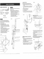
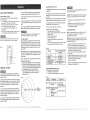
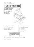
Owner's
Manual
1 HP (Max, DeveUoped)
1410 and 2600 FoP.M.(No Load)
Leg Stand
12" BAN
SAW
Mode! No.
137.224120
Safety instructions
installation
CAUTmON:
Before using this band saw,
read this manual and follow
all its Safety Rules and
Operating Instructions.
• Operation
o Maintenance
Parts List
Custemer
Help
Line
t =8ee=843.1¢82
Sears,
Roebuck
and Coo, Hoffman
Part No. 137224120002
Estates,
JL 60179
USA
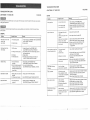
GENERAL
SECTRON
Warranty
................................................................
Product
Specifications
.....................................................
Safety
_nstructions
........................................................
Accessories
and Attachments
. : .............................................
Carton
Contents
..........................................................
Know Your Band Saw ......................................................
2
2
3
6
G
8
Glossary
of Terms
........................................................
Assembly
and Adjustments
................................................
Operation
..............................................................
Maintenance
............................................................
Troubaeshooting
guide
....................................................
Parts
..................................................................
BLADE iNCLUDED
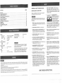
MOTOR
Power source .......
Horsepower .........
Speeds
High .....
Low ......
Type ..............
!20 V AC, 60 HZ, 7.5 AMPS
1 HP (Max. Developed)
2600 RP.M.
1410 RP.M.
Induction
CUTTING CAPACITY
Throat .............
Height .............
12-1/2"
6"
TABLE
Size ...............
Tilt ................
INSTRUCT ONS
PAGE
BEFORE
BLADE CAPACITY
Width ...........
Length .............
SAFETY
":..
!/8", 1/4", 3/8", 1/2"
91"
14" x 14"
0 - 10 ° Left, 0 - 45 ° Right
DUST COLLECTION
...........
MITER GAUGE ................
BAND
SAW
To avoid mistakes that could cause serious injury, do not
plug the band saw in until you have read and understood
the following:
3/8" x 91 "16 TPI
1.
READ and become familiar with this entire instruction
manual. LEARN the tool's applications, limitations, and
possible hazards.
2.
KEEP
3.
REMOVE ADJUSTING KEYS AND WRENCHES. Form
the habit of checking to see that keys and adjusting
wrenches are removed from the tool before turning ON.
4.
Yes
Yes
,
.
To avoid electrical hazards, fire hazards, or damage to
the tool, use proper circuit protection. Use a separate
electrical circuit for your tools.
,
"Yourband saw is wired at the factory for 120V operation,
Connect to a 120V, 15 AMP time delay fuse or circuit
breaker. To avoid shock or fire, replace power cord
immediately if it is worn, cut or damaged in any way.
Some dust created by power sanding sawing, grinding, drilling, and other construction activities contains chemicals
known [to the State of California] to cause cancer, birth defects or other reproductive harm. Some examples of these
chemicals are:
@ Lead from lead-based paints.
@ Crystalline silica from bricks and cement and other masonry products, and
@ Arsenic and chromium from chemically-treated lumber.
Your risk from these exposures varies, depending on how often you do this type of work. To reduce your exposure to
these chemicals: work in a well ventilated area, and work with approved safety equipment, such as those dust masks
that are specially designed to filter out microscopic particles.
THE
Safety is a combination of common sense, staying alert
and knowing how to use your band saw.
9
10
18
21
22
24
............
USING
i:!
=ii
/
GUARDS
iN PLACE
and in working
order.
11. WEAR PROPER APPAREL. DO NOT wear loose
clothing, gloves, neckties, rings, bracelets, or other
jewelry which may get caught in moving parts. Non-slip
footwear is recommended. Wear protective hair covering
to contain long hair.
!2.
ALWAYS WEAR EYE
PROTECTION. Any band saw
can throw foreign objects into
the eyes which could cause
permanent eye damage.
ALWAYS wear Safety Goggles
(not glasses) that comply with
ANSI safety standard Z87.1. Everyday eyeglasses
have only impact-resistant lenses. They ARE NOT safety
glasses. Safety Goggles are available at Sears. NOTE:
Glasses or goggles not in compliance with ANSI Z87.1
could seriously hurt you when they break.
WP.AR YO_
13. WEAR A FACE MASK OR DUST MASK. Sawing and
sanding operations produce dust.
KEEP WORK AREA CLEAN. Cluttered areas and
benches invite accidents.
14. SECURE WORK. Use clamps or a vise to hold work
when practical. It's safer than using your hand and it
frees both hands to operate tool.
DONq" USE IN A DANGEROUS ENVIRONMENT. Don't
use power tools in damp or wet locations, or expose
them to rain. Keep work area well lighted.
15. D_SCONNECT TOOLS before servicing, and when
changing accessories, such as blades, bits, cutters,
and the like.
KEEP CHILDREN AWAY. All visitors should be kept at
a safe distance from the work area.
16. REDUCE
MAKE WORKSHOP KID-PROOF with padlocks,
master switches, or by removing starter keys:
8.
DON'T FORCE THE TOOL. It will do the job better and
safer at the rate for which it was designed.
9.
USE THE RIGHT TOOL. Don't force the tool or the
attachment to do a job for which it was not designed.
t0. USE PROPER EXTENSION CORD. Make sure your
extension cord is in good condition. When using an
extension cord, be sure to use one heavy enough to
carry the current your product will draw. An undersized
cord will result in a drop in line voltage and loss of
power which wilt cause the tool to overheat. The table
on page 5 shows the correct size to use depending on
cord length and nameplate ampere rating. If in doubt,
use the next heavier gauge. The smaller the gauge
number, the heavier tSe cord.
THE R_SK OF UNINTENTIONAL
STARTING.
Make sure the switch is in OFF position before plugging
in.
17. USE RECOMMENDED
ACCESSORIES. Consult the
owner's manual for the recommended accessories. The
use of improper accessories may cause risk of injury
to persons.
18. NEVER STAND ON TOOL. Serious injury could occur
if the tool is tipped or if the cutting tool is unintentionally
contacted.
t9. CHECK FOR DAMAGED PARTS. Before further use
of the tool, a guard or other part that is damaged
should be carefully checked to determine that it will
operate properiy and perform its intended function.
Check for alignment of moving #_rts, binding of moving
parts, breakage of parts, mounting, and any other
conditions that may affect its operation, A guard or
other part that is damaged should be properly repaired
or replaced.
:!
SAVE THESE
NSTRUCT ONS
_i_!_i;!i`_!_:i:_:_!;:_i_!_;_;:_!_;!_:_i:_!:!_:!_i!_ii:i;:_!_i!:i;_:_!_:_!_!:_:_i:::::_i:_:_:_!_:::_:::_:i_:i!_:ii_!_!:i:i_!:_:iJ_i!;!i_
_i:!_::il;_:iii_:_!i!i:iii:i';:::::_i_:i_,:i:::',!:i:_!:!i:i':!
¸_::_!::ii_:::!;_i:_
:¸i!!_::i;:i_i!;:!:i:::::;:
¸!II:_;::
¸_::!:i!,:!i
¸i:!:::!:
¸,i'i::!_!i
¸:iii:i
¸!I:I
¸i::::;:i:!i_::i
3 :!_,i::i
¸::i::i
¸I:,!!;I::::I:!_:
¸!_::::_::ii::i
¸:::;!:I!_:_;::
¸:_I:::
¸i:_:_i::::i::::::i:;!;;i_:;i:_!:'::::_!:::!i
¸=_::i::!;;:?:i::_::::i:!ii;_:i:!i!:!:::_:i!::_:_
i::::
¸i:_:::_:::i:_::!_:;!::_i:_:i;:_:!!:!:!:!ii:_i!i:i:!i:i:i:::::
:!ii::_:i:::_:_:_:!i
¸i:::'!:_::::i!:_i::i:ii
¸_:!i:;_i_!_!ii:!:!i':_i!i:i,:i_
_0. NEVER LEAVETOOL RUNNING UNATTENDED.
TURN THE POWER OFF. Don't leave the tool until it
comes to a complete stop.
11. PLAN intricate and small work carefully to avoid
pinching the blade. Avoid awkward operation and hand
positions to prevent accidental contact with the blade.
!1. DON'T OVERREACH. Keep proper footing and balance
at all times.
12. SMALL PIECES should be secured with jigs or
fixtures. Do not hand hold pieces that are so small your
fingers are under the blade guard.
!2. MAINTAIN TOOLS WITH CARE. Keep tools sharp and
clean for best and safest performance. Follow
instructions for lubricating and changing accessories.
!3. DO NOT use power tools in the presence of flammable
liquids or gases.
'.4. DO NOT operate the tool if you are under the influence
of any drugs, alcohol or medication that could affect
your ability to use the tool properly.
tool, use proper circuit protection. Use a separate electrical
circuit for your tools.Your saw is wired at the factory for
120V operation. Connect to a 120V, 15 Amp circuit and
use a I5 Amp time delay fuse or circuit breaker. To avoid
shock or fire, if power cord is worn or cut, or damaged-in
any way, have it replaced immediately.
I3. SUPPORT round work properly (with a V-block or
clamped to the miter gauge) to prevent it from rolling
and the blade from biting.
GROUNDING
14. CUT only one workpiece at a time. Make sure the table
is clear of everything except the workpiece and its
guides before you turn the saw on.
This tool must be grounded while in use to protect the
operator from electrical shock.
15. MAKE RELIEF CUTS when cutting long curves.
;PECIFgC
17. TO FREE any jammed
DO NOT MODIFY THE PLUG PROVIDED. If it will not fit
the receptacle, have the proper receptacle installed by a
qualified electrician.
18. DON'T LEAVE the work area until all moving parts are
stopped. To childproof the workshop, shut off the power
to master switches and remove the switch key from the
band saw. Store it in a safe place, away from children.
IMPROPER CONNECTION of the equipment grounding
conductor can result in risk of electric shock. The
conductor with the green insulation (with or without yellow
stripes) is the equipment grounding conductor. If repair
or replacement of the electric cord or plug is necessary,
DO NO[ connect the equipment grounding conductor
to a five'terminal.
material, turn the switch OFR
Remove the switch key and unplug the saw. Wait for all
moving parts to stop before removing jammed material.
TO AVOID INJURY from unexpected movement, make
sure the saw is on a firm, level surface, properly secured
to prevent rocking. Make sure there is adequate space
for operating. Bolt the saw to a support surface to
prevent slipping, walking, or sliding during operation.
TURN the saw OFF and unplug the saw before
moving it.
USE THE
CORRECT
USE blades
For your own safety, read the entire instruction manual
before operating the band saw.
t. Wear eye protection.
2. Do not wear gloves, necktie, or loose clothing.
3. Make sure the saw is on a firm level surface and
properly secured.
4. USE ONLY THE RECOMMENDED ACCESSORIES.
5. Use extra caution with very large, very small, or
awkward workpieces.
6. Keep hands away from the blade at all times to
prevent accidental injury.
,
Do not remove jammed cutoff pieces until blade has
stopped.
8. Maintain proper adjustment of blade tension, blade
guides, and thrust bearings.
9. Adjust upper guide to just clear workpiece.
10. Hold workpiece firmly against table.
size and style of blade.
recommended
at 2600
FPM or greater.
MAKE SURE the blade teeth point down and towards
the table.
BLADE GUIDES, SUPPORT BEARINGS, AND
BLADE TENSION must be properly adjusted to avoid
accidental blade contact and to minimize blade
breakage. To maximize blade support, always adjust
the upper blade guide and blade guard so that it is
1/8 inch above the workpiece.
TABLE LOCK HANDLE should be tight.
USE EXTRA CAUTION with large, very small or
awkward workpieces.
USE EXTRA SUPPORTS to prevent workpieces from
sliding off the table top. Never use another person in
place of a table extension, or to provide additional
support for the workpiece.
0. WORKPIECES must be secured so they don't twist,
rock, or slip while being cut.
SAVE THESE
ELECTRICAL
REQUHREMENTS
POWER
AND
SUPPLY
MOTOR
SPEC_FICATIONS
To avoid electrical hazards, fire hazards, or damage to the
NSTRUCTRONS
4
CHECK with a qualified electrician or service person if you
do not completely understand the grounding instructions, or
if you are not sure the tool is properly grounded,
USE ONLY 3-wire extension cords that have 3-prong
grounding plugs and 3-pole receptacles that accept
the tool's plug. Repair or replace damaged or worn
cord immediately.
Use a separate electrical circuit for your tools. This circuit
must not be less than #12 wire and should be protected
with a 15 Amp time lag fuse. Before connecting the motor
to the power line, make sure the switch is in the OFF
position and the electric current is rated the same as the
current stamped on the motor nameplate, Running at a
Lower voltage will damage the motor.
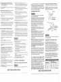
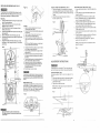
This tool is intended for use on a circuit that has a receptacle
like the one illustrated in FIGURE A. FIGURE A shows a
3-prong electrical plug and receptacle that has a grounding
conductor. If a properly grounded receptacle is not available,
an adapter (FIGURE B) can be used to temporarily connect
this plug to a 2-contact ungrounded receptacle.
The temporary adapter should be installed by a qualified
technician. The adapter (FIGURE B) has a rigid lug
extending from it that MUST be connected to a permanent
earth ground, such as a properly grounded receptacle box.
THE TEMPORARY ADAPTER SHOULD BE USED ONLY
UNTIL A PROPERLY GROUNDED OUTLET CAN BE
3-Prong Plug
Fig. A
IN THE EVENT OF A MALFUNCTION OR BREAKDOWN,
grounding provides a path of least resistance for electric
current and reduces the risk of electric shock. This tool is
equipped with an electric cord that has an equipment
grounding conductor and a grounding plug. The plug
MUST be plugged into a matching receptacle that is
properly installed and grounded in accordance with ALL
local codes and ordinances.
16. ALWAYS WATCH the saw run before each use. If there
is excessive vibration or unusual noise, stop immediately.
Turn the saw off. Unplug it immediately. Do not start
the saw again until the problem has been located and
corrected.
INSTRUCTBONS
CAUTION: In all cases, make certain the receptacle is
properly grounded, tf you are not sure have a qualified
electrician check the receptacle.
INSTRUCTIONS
;5. ALWAYS operate the band saw in a wellwentilated area
and provide for proper dust removal. Use dust collection
systems whenever possible. Dust generated from
certain materials can be hazardous to your health.
SAFETY
INSTALLED BY A QUALIFIED ELECTRICIAN. The
Canadian Electrical Code prohibits the use of adapters.
Properly Grounded
3-Prong Receplacte
Fig. B
Grounding Lug
Make Sure This
is Connected
to a
Known Ground
-Prong
eceptacle
This band saw is for indoor use only, Do not expose to rain
or use in damp locations
GUIDEUNES
FOR
EXTENSION
CORDS
USE PROPER EXTENSION CORD. Make sure your
extension cord is in good condition. When using an
extension cord, be sure to use one heavy enough to carry
the current your product will draw. An undersized cord will
result in a drop in line voltage and in loss of power which will
cause the tool to overheat. The table below shows the
correct size to use depending on cord length and nameplate
ampere rating. If in doubt, use the next heavier gauge. The
smaf]er the gauge number, the heavier the cord.
Be sure your extension cord is properly wired and in
good condition. Always replace a damaged extension cord
or have it repaired by a qualified person before using it.
Protect your extension cords from sharp objects, excessiv
heat and damp or,wet areas.
(when using 120 volts only)
In feet
notmorethan
25'
50'
0
6
18
16
16
t4
6
10
t8
16
14
12
10
t2
16
16
14
t2
12
16
14
!12
Not recomrnended
more than
...........
100'
,
SAVE THESE INSTRUCTIONS
150'
............................
i
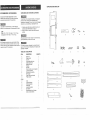
UNPACKUNG YOUR BAND SAW
::{ECOMMENDED
UNPACKING
ACCESSORUES
'isit your Sears Hardware Department or see the
;raftsman Power and Hand Tool Catalog to purchase
_commended accessories for this power tool.
AND CHECKING
CONTENTS
To avoid injury from unexpected starting, do not plug the
power cord into a power source receptacle during
unpacking and assembly. This cord must remain unplugged
whenever you are assembling or adjusting the saw.
O avoid the risk of personal infury, do not modify the
ower tool or use accessories not recommended by Sears.
1.
Carefully unpack the band saw and aU its parts, and
compare against the illustration on page 7.
Place the saw on a secure surface and examine it
carefully.
2.
ITEM
Blade: 1/8", 1/4", 3/8", 1/2" wide, 91 "- 91 1/2" long
Sandpaper belt: 1/2" wide, 91"- 91 1/2" tong
E
C
B
Although compact, this saw is heavy. To avoid back injury,
get help whenever you have to lift the saw.
Ise of improper accessories may cause hazards. Follow
]structions that accompany accessories. Do, not use any
ccessory unless you have completely read the instruction
r owner's manual for that accessory.
If any part is missing or damaged, do not plug the band
saw in until the missing or damaged part is replaced, and
assembly is complete.
TABLE
_TEM
A
B
C
D
E
F
G
H
I
J
K
L
M
N
STAND:
O
P
Q
R
S
T
U
6
OF LOOSE
PARTS
DESCRIPTION
QUANTITY
Band saw
Table w!insert
Trunnion
Star handle table knobs
Table alignment pin
Medium hex bolts
Washers
Hex nuts
Short hex bolts, nut, and washers
Long hex bolt w/nut
Saw dust port assembly
Miter gauge
Power cord wrap brackets
Phillips screws
Legs
Long leg brackets
Short leg brackets
Plastic feet
Leg stand top plate
Hex wrench
Miscellaneous bag of carriage
bolts, nuts and washers
H
G
A
1
t
1
2
1
4
8
4
2
1
1
1
2
2
4
2
2
4
1
1
J
i
M
K
0
N
O0
i
O_
0[3
I
O0
O0
O0
O0
P
R
o
Q
S
T
U
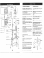
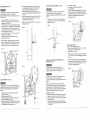
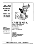
Upper blade wheel
upper cover
Lower blade
support bearing
CRAFTSMAN
Lower
guide
Blade guard
Upper blade
support bearing
)er blade guide
Blade
Table insert
--
ON/OFF
Miter slot
Lower
Blade tension
knob
Table
lock knob
Saw pulley
Lower
blade wheel
V Belt
pulley
Blade
Upper guide
lock knob
Power cord wrap
Table
Motor
pin
Table tilt scale
Rubber
tire
Motor
Sawdust
HEEL - Misalignment of the blade.
BLADE GUIDES - Support the blade and keep it from
twisting during operation. Blade guides must be adjusted
when the blade is changed or replaced.
KERF- The material removed by a blade in a through cut,
or the slot produced by the blade in a non-through or
partial cut.
BLADE TENSION KNOB -Controls
tension when changing blades.
LEADING EDGE -The
the cutting tool first.
the amount of blade
MITER CUT - An angle cut made across the width of a
workpiece.
IDLE WHEEL HANDLE - Moves the idle wheel for proper
tensioning of the V-belt.
RESAW -A cutting operation to reduce the thickness of
the workpiece to make thinner workpieces.
ON 1 OFF SWITCH - Has a built-in child safety lock. To
lock the switch in the OFF position, remove the switch key
from the switch.
RESIN - A sticky sap that has hardened.
R_PPING CUT -A
workpiece.
SAWDUST PORT - Helps keep the machine free from
sawdust. The sawdust port makes an excellent hook-up for
a wet/dry vacuum.
SAW BLADE PATH -The area of the workpiece or table
top directly in line with the travel of the blade or the part of
the workpiece which will be cut.
TABLE LOCK KNOB - Locks the table in place.
SET -The distance between two adjacent saw blade teeth
tips bent outward in opposite directions to each other.
The further apart the tips are, the greater the set.
UPPER GUIDE LOCK KNOB - Locks the upper slide. Use
it after you adjust the upper guide assembly to make sure
the upper blade guide just clears the workpiece before
cutting. Upper guide lock knob must be tightened before
the band saw is turned on.
TRAILING END - The workpiece end last cut by the blade.
WORKPIECE -The item being cut. The surfaces of a
workpiece are commonly referred to as faces, ends, edges.
cord
WOODWORKING
TERMS
WORKTABLE -The surface on which the workpiece rests
while performing a cutting or sanding operation.
Table trunnion
Mounting
holes
Miter gauge
in holder
Stand top
plate
BEVEL CUT - An angle cut made through the face of a
workpiece
COMPOUND CUT - A simultaneous bevel and miter cut.
CROSSCUT - A cut made across the width of the
workpiece.
Leading,_
Relief cu_
Sawblade Path
Kerf
RELIEF CUT - Removal of waste material by a cut from
the outside edge, allowing easier cutting of intricate curves.
Stand
cutting operation along the length of the
R.P.M. - Revolutions per minute. The number of turns
completed by a spinning object in one minute.
port
Table tilt stop bolt
end of the workpiece pushed into
BLADE TRACKING KNOB -Adjusts the blade position so
the blade always runs in the center of the wheel.
TILT {BEVEL) SCALE - Shows the degree the table is
tilted for bevel cutting.
Idle wheel
handle
aligning
SAW TERMS
tra_cking
knob
Mounting hole
Idle wheel
Motor
Table removed for clarity
of illustration
BAND
Surface
F.P.M. - Feet per minute. Used in reference to the surface
speed of the saw blade.
FREEHAND - Performing a cut without using a fence
(guide), hold-down or other proper device to prevent the
workpiece from twisting during the cutting operation.
GUM -A
Workptece
sticky sap-based residue from wood products.
9
\
Trailing Edge
FIG. 0-1
ASSEMBLE THE TABLE
,SSEMBLY
NSTRUCTIONS
Although compact; this saw is heavy. To avoid back injury,
get help to lift the saw.
Phillips screwdriver
Adjustable wrench
Combinationsquare
Straight edge
ASSEMBLE BAND SAW TO LEG STAND (F_G. B)
t. Lift the saw body (1) and place on the leg stand (2),
aligning with the four mounting holes (3).
2. Attach the band saw to the stand with four long hex
head bolts (4) and four flat washers (5).
3. Place a flat washer (5) and hex nut (6) on each bolt
from the underside. Hand tighten.
4. Tighten all bolts and nuts with a wrench.
Mounting the trunnion support bracket (F_G. C)
1. Place the trunnion support bracket (1) on the saw body,
as shown,
2. Insert two tong hex head bolts (2, 3) with flat washers (4)
into the threaded holes, through the bracket and saw
body.
3. Open the lower wheel cover (5).
4. Thread a hex bolt (2) Tighten.
5, Close the wheel cover.
6. Thread a nut (7) onto the table stop bolt (8) and screw
both into the rear tab (9) on the trunnion support bracket.
4
3
Mounting the table (FIG. D, E)
7. Remove the table insert (10) and table aligning pin (11)
from the table (12).
8. Guide the table slot (13) over the saw blade and rotate
a 1/4 turn, so4he slot is perpendicular to the blade.
Feeler gauge - size 0.02
FIG. B
FIG. D
or your safety, never connect plug to power source
._ceptacle until all assembly and adjustment steps are
)mpleted, and you have read and understood the safety
nd operating instructions.
EG STAND ASSEMBLY (FIG. A)
Lay the top plate (1) upside down on a flat surface.
Attach a ieg (2) to the outside of the stand top plate
with two carriage bolts (3), washers (4), and nuts (5).
Do not tighten.
Repeat for the remaining three legs.
Attach two long brackets (6) and' two short brackets (7)
to the inside of the legs using carriage bolts (3),
washers (4), and nuts (5). Do not tighten,
Place the leg pad s (8) on each leg and turn the leg
stand' upright on a firm level surface.
Tighten all bolts and nuts with a wrench.
12
13
10
4
5
,
10.
11.
ASSEMBLE
I
1
I
FIG. A
7
5
THE SAWDUST
COLLECTION
PORT
(FIG.0-I)
I. Slidethehook (I)on theportassembly intothesquare
hole(2)locatedon thebandsaw housing,below the
lowerbladeguides.
2. Push the flat plate of the port against the outside of the
band saw to align the holes (3).
3. P_ace a washer (5) on the screw (4), insert and tighten.
12.
13,
Place the table (12) into the support bracket (1), guiding
the bolts (14)in the scale brackets through the holes in
the trunnion bracket (1).
Align the 0 ° mark on the scale to the pointer (15) on
the trunnion.
Attach the star handle table !ock knobs (16) to the bolts
and tighten. (FIG. E)
Replace the table insert (10), aligning the indents,
Place the table aligning pin (11) in the front of the table,
into the slot (i3), and tighten. (FIG. D)
FIG. E
14
NOTE: When operating the band saw, for best sawdust
exhaust attach a dust collection or vacuum hose.
4
i.
ii_ii;i!i_i_i!ii_!!_!_!_i:;i_i_i'_i:_
_:';:!i:ili_iii:ii:i
!_i_i_!ii_!;!i!i!!_i_i_!_;_!_!_i!!i_i!_i_i_;i_!;_i!ii_i:_i!_;_i
_i,;:i::!i:i!_:ii_!;i,!_!,!;i;!:i
i:i:
_i:ii_::::i:ii!_i;_i:i_iiii';i_i:i!:i!i!:_i!_ii!i:!_i:iii_:i!iii:
¸i::i!i:;_i_i_:i
:!;!'i;ii,ii!_;,_;:ii:ii::i_::_i_ii::iii_!;:_!_:i:_!!iiii
!:i:_11 _!i_!_;!•_:_:::_!!_;i_:_:_i_:_i_:!!:::_!i!_:_i_!;_;_!_;_i_!i_!_;_!_:_!:_!!:_:_!:_i_;i
:_::i_::!_i:i_i!;;_:,_!!i:i;_i!i!
_;:_!i_i,!_ii_i;i;_!:;!i::i;!i,!i_!:i!i:i
_i!,i:!
_!
!::_i;:;_!:;_:_:i:!i
i_:::i_:!i:ii;iiii_!::i_i::i;ii_'ili,i_il;:::i_;::,!i!i
!:_ili:!iii:_il
!:!_ii:_:_
ii'i_:i:!;!;_ii;_ii_:i_:!_i
....
:
••:
•
iL
¸
/
_•Li
::•::
......
• ••••
::
•:::
•::/
i:_:
: :::
•
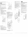
iNSTALLiNG
AND REMOVING BLADES
(FIG F)
Fig
F-1
To avoid injury from accidental starting, always turn the
switch OFF and remove the plug from the power source
before moving, replacing, or adjusting the blade.
Removing
1. Loosen the blade tension by turning the blade tension
knob (1) counterclockwise.
2. Remove the table insert (2) and remove the table
aligning pin (3) from the fable.
3. Pull the cover knobs to open the upper and lower
wheel cover doors (4).
4. Loosen the two phillips screws (5) and remove the upper
blade guard (6).
5. Remove the blade (7) from the blade guides (8).
6. Carefully pull the blade from the side slot (9) and from
the wheels (!0).
7. Swing the left side of the blade toward you, turning
the blade so it will fit through the slot (11) in the table,
and remove.
FiG. F
FiG. H
Installing
1. Make sure the blade tension knob (1) is turned
counterclockwise untit it stops.
2. Remove the table insert (2) and the table aligning pin (3)
from the tabfe.
3. Open tile upper and lower wheel cover doors (4),
4. Loosen and remove the blade guard (6).
5. Guide the new blade (7) through the table slot (11),
making sure the blade teeth are pointing forward and
down.
7.
8.
to
9.
10
11.
_5
NOTE: The table stop bolt must be lowered
table 10 ° to the left,
NOTE: To avoid lifting the workpiece, the blade teeth
must point downward toward lhe table.
6.
--1
ADJUSTING THE 90' TABLE STOP (FIG. J)
1. Loosen the table aock knobs (t) and tilt the table to the
right.
2. Loosen the jam nut (2) on the table stop bolt (3) and
lower the stop bolt.
3. Tilt the table to the left until it rests on the stop bolt.
4. Place a combination square (4) on the table with the
heel of the square against the blade (5).
5. Adjust the tilt of the table left or right until it is 90 ° to
the blade and there is no space between the square
and the blade. Tighten the table lock knobs.
6. Adjust the table stop bolt (3) up until it touches the table.
Tighten the jam nut (2).
7. Loosen the lock knobs and see that the table is resting
on the stop bolt.
8. Check the square to make sure the table is still square
to the blade. If not, readjust the stop bolt.
9. When the adjustment is accurate at 90 °, align the
pointer (6) on the scale (7) to 0 °
_NSTALL POWER CORD BRACKETS (FIG. H)
t. Power cord brackets (1) are provided for convenier_t
cord storage. Attach the power cord brackets to the back
of the saw body, as shown, with two pan head screws (2).
Tighten.
2. Connect the band saw short power cord (3), to
the motor power cord (4).
j6
12.
Swinging the left side away and back, place the blade
on the upper and lower wheels (10).
Place the blade carefully between the upper and lower
blade guides (8).
Slide the blade into the slot (9) at the left of the wheels,
and make sure the blade is positioned at the middle of
the wheels.
Turning the blade tension knob clockwise, tighten the
tension until the blade is tight on the wheels,
Replace the table insert and the table aligning pin.
Adjust the btade tracking and tension propedy (See
ADJUSTMENT iNSTRUCTIONS section) before
operating the band saw,
Push the wheel cover doors closed.
7
2
To avoid injury,
,tt
lowerguides and bearingsmust be properly adjusted before
operating the band saw.(See ADJUSTMENTINSTRUCTIONS
the blade
tension, tracking,
and upper
and
section)
MITER GAUGE (FIG. G)
A miter gauge (I) is supplied with your band saw to be used
with the table (2). The table is equipped with a slot on the
right side of the blade fo=' the miter gauge. The miter gauge
can be tilted 0' to 45" right or left. A bracket is provided on
the leg stand for convenient miter gauge storage.
to tilt the
FIGo J
5
ADJUSTMENT
iNSTRUCTIONS
To avoid injury, turn the switch OFF and unplug the band
saw from the power source before making any adjustments.
TiLTiNG THE TABLE {F2G. I)
The band saw table (1) tilts 0° to 45 ° to the right and 10° to
the left.
!. Loosen both table lock knobs (2) underneath the table.
2. Tilt the table to the desired angle on the scale (3)
underneath the table.
3, Tighten the two table lock knobs.
7
NOTE: The 90 ° table stop bolt must be lowered to tilt
the table I0 ° to the left.
¢
1
F_G. !
3
!
FiG, G
lO
Make sure the blade is in center of table insert stot(2)
Then Tighten the screw(A-C) which under the tabe both side..
_2
as shown Fig Fq
_
•
_
:
i¸ ¸ •::
•:
•
,••
•::••
•••• •
•
13
• •
•• •
:
•
•
i:
•_:
: : :/ / :
+'-/!i
¸:I
ILADETENSION
(FIG. K, K-l)
5.
6.
b avoid injury, turn the switch OFF and disconnect the
aw from the power source before making any
djustments. NEVER make tension adjustments with the
lachine running.
Loosen the butterfly nut (6) and the rolled nut (7)
located on the back of the band saw, under the blade
tracking knob (5). (FIG. K-l)
The upper wheel (I) is spring loaded. Adjust the blade
tension by raising or lowering the upper wheel. {FIG. K)
Turn the blade tension knob (2) clockwise to raise the
wheel and tighten the blade, counterclockwise to lower
the wheel and loosen the tension.
As you become familiar with the saw, you may want to
change the tension settings.
Complete the blade tracking adjustments before
operating the band saw.
7.
If the blade moves toward the front of the wheel, turn
the tracking knob (5) clockwise. This tilts the top of the
wheel and moves the blade toward the center.
If the blade moves toward the back edge, turn the
tracking knob counterclockwise, moving the blade toward
the center.
Tighten the butterfly nut (6) and the rolled nut (7) after
you have completed the "Blade tension" and "Blade
tracking" adjustments. (FIG. K-l)
NOTE: Turn the tracking knob SLIGHTLY to make blade
tracking adjustments.
UPPER BLADE GUIDE ASSEMBLY
5.
6.
{F_G. M)
7.
To avoid injury, turn the switch OFF and disconnect the
saw from the power source before making ar_y
adjustments. NEVER make adjustments with the machine
running.
1.
2.
Loosen the lock knob (1) and move the blade guide
assembly (2) up or down to 1/8" above the workpiece.
Tighten the lock knob.
8.
9.
Tighten the set screws.
Loosen the side set screw (4) by turning
counterclockwise.
Move the blade guide bracket shaft (5) in or out until
the guides are at least t/32" behind the blade teeth.
The guides must remain behind the blade teeth during
operation to prevent damage to the saw blade.
Tighten the set screw.
FmGoN
FIG. K-!
3
7
6
5
4
\
NOTE: Changes in blade width and type of material
being cut will have an effect on the blade tension. Too
much or too tittle tension could break the blade. When
the band saw is not in use, relax the blade tension.
Support bearing (FIG. O)
10. Loosen the bearing set screw (6).
11. Move the support bearing shaft (7) in or out, until the
bearing (8) is 1/64" behind the blade.
12. Tighten the set screw (6).
FIG. K
NOTE: The blade support bearing prevents the blade
from moving back too far and damaging the saw teeth
setting.
UPPER
BEARING
RG. L
_',LADETFIACKING
(FIG. K-l, L)
BLADE
GUIDES
AND BLADE
SUPPORT
(FIG. N, O)
The blade guard has been removed for clarity of
illustration. To avoid injury never operate the band saw
without all guards in place and in working order.
To avoid injury, turn the switch OFF and disconnect the
saw from the power source before making any
adjustments. NEVER make adjustments with the machine
running.
b avoid injury, turn the switch OFF and disconnect the
.aw from the power source before making any adjustments.
4EVER make tracking adjustments with the machine
unning.
NOTE: Make sure the blade is tensioned and tracking
properly. Adjust the blade guides and support bearing after
each blade tension and tracking adjustment. When the
upper blade guides and support bearings are adjusted, the
lower guides and bearings should also be adjusted.
The blade (1) must be tensioned properly before
adjusting the tracking.
Open the upper cover. (FIG. L)
Move the blade guides (2) and support bearings (3)
away from the blade, if necessary.
Rotate the wheel (4) slowly forward by hand, and check
the position of the blade on the wheel. The blade should
remain centered on the wheel as it turns.
Blade guides (FIG. N)
1. Make sure the blade is tensioned and tracking properly.
2. Loosen the front set screws (1) with a hex wrench.
" as close to the ,.,,,=de
"'_
(3) as possible
3. Move the guides (_;
without pinching it.
4. Using a feeler gauge, make sure the space between
each guide and the blade measures 0.02" (the thickness
of a dollar bill.)
13. Check the lateral position of the support bearing (8).
The vertical back edge of the blade (3) should overlap
the front face of the support bearing 1/16" to 1/8" to
the left of the right bearing edge.
FroG.O
7.
LOWER
BLADE
GUIDES
AND
SUPPORT
BEARING
FIG, Q
8.
8
9.
To avoid injury, turn the switch OFF and disconnect the
saw from the power source before making any
adjustments. NEVER make adjustments with the machine
running.
f
1 t.
12.
NOTE: Make sure the blade is tensioned and tracking
properly.
7
FIG. P
3
.......
t3,
6
NOTE: The lower blade guides and support bearings
should always be adjusted after the blade is tensioned, the
tracking is adjusted, and the upper blade guides and upper
support bearings are properly adjusted.
Blade guides
{FIG. P)
1. Loosen both front set screws (1) with a hex wrench.
2.
Move the guide (2) as close to the sides of the blade (3)
as possible without pinching it.
3.
U,Cing the feeler gauge, measure the spaces between
the guide and the blade. Adjust to 0.02".
4. Tighten the hex screws.
5. Loosen the side set screw (4). Move the guide
support bracket (5) in or out until the guides are at
least 1/32" behind the saw teeth. Tighten the screw.
10.
14.
FIG. S
PULLEY ALIGNMENT {F}G. R, S)
This alignment is adjusted at the factory and should not
need to be readjusted. However, if there are belt tracking
problems do the following:
1. Pull the cover knobs to open the wheel covers. (F}G. R)
2. Loosen and remove the lower blade wheel hex head
bolt (1) and flange (2) with an adjustable wrench.
3. Loosen the blade tension by turning the blade tension
knob (3) counterclockwise, following the steps in
"Blade Tension".
4. Remove the saw blade (4) from the lower blade
wheel (5).
5. Remove the lower blade wheel from its shaft.
i
ij
Support bearing (FIG. Q)
6. Loosen the bearing set screw (6) with the hex
wrench.
7. Move the blade support bearing shaft (7) in or out until
the support bearing (8) is 1/64" behind the saw blade.
8. Tighten the bearing set screw.
9. The blade support bearing should be adjusted so the
vertical back edge of the blade (3) overlaps the front
face of the support bearing approximately 1/t6 to t/8".
Remove the v-belt (6) from the motor pulley (7).
(FIG. S)
Place a straight edge in the front groove of both
pulleys.
tf the side edges of the pulleys are not aligned, loosen
the motor pulley hex socket screw (8).
Adjust the motor pulley in or out on the motor shaft to
align the side edges of both pufteys.
When aligned, tighten the hex socket screw.
Place the v-belt on the motor pulley and saw pulley.
Check the belt tension and adjust.
Move the idle wheel (9) to press the V-belt, by turning
the handle (10).
Replace the blade wheel and blade.
2
t
5
6.
Loosen the idie wheel (9) using the idle wheet handle (I0)
on the back of the band saw.
10
To avoid injury, the belt tension, the blade tension, tracking,
and upper and lower guides and bearings must be properly
adjusted before operating the ba_ndsaw.
BELT TENSION {FIG. T)
The belt tension may need adjusting if the belt is replaced
(See MAINTENANCE Section), or the blade speed is
changed (See OPERATION Section).
1. Loosen the idle wheel by turning the idle wheel handle.
2. Loosen the motor mount nuts (1) and slide the
motor (2) sideways to increase or decrease the belt
tension.
3. The belt tension is correct when there is a 1/2"
deflection if the belt is pressed in the center between
pulleys.
4. When positioned properly, tighten the motor mount
nuts.
5. Tighten the idle wheel handle to press the idle wheel
against the V-belt.
NOTE: Do not overtighten the motor mount nuts,
tighten just enough to maintain the belt tension.
\
F_G. T
t_)
f rfd/I
!
BLADE SELECTION
(FIG.W)
CAUTION: Blade teeth are sharp. Use care whenhandling
a saw blade.
3AS!C SAW OPERATIONS
Sharp saw blades need little pressure for cutting. Steadily
move the workpiece against the blade without forcing it.
ON/OFF" SWITCH (FIG. U)
he keyed switch is intended to prevent unauthorized
_seof the band saw.
To turn the band saw ON insert the yellow key (1) into
the key slot (2) in the center of the switch.
'.. Push the key firmly into the slot, then push switch
to the ON position to start the band saw.
I. To turn the band saw OFF push the switch to the
down position.
Remove the yellow switch key, when the saw has come
to a complete stop, by gently pulling it outward.
To avoid twisting the blade, do not turn sharp corners or saw
around corners.
_emove the switch key whenever the saw is not in use.
_lace it in a safe place and out of reach of children.
CUTTING CURVES
When cutting curves, carefully turn the workpiece so the
blade follows without twisting. If the curve is so sharp that
you repeatedly back up and cut new kerf, use a narrower
blade, or a blade with more set (teeth further apart). When
a blade has more set, the workpiece turns easier but the
cut is rougher.
=IG. U
A band saw is basically a "curve-cutting" saw. It is not capable
of doing intricate inside cutting as can be done with a scroll
saw.
tt is also used for straight line operations such as crosscutting,
ripping, mitering, beveling, compound cutting, and resawing.
To avoid blade breakage, fire or other damage or injury,
NEVER use this band saw to cut ferrous metals.
When changing a cut, do not withdraw the workpiece from
the blade. The blade may get drawn off the wheels. To change
a cut, turn the workpiece and saw out through the scrap
material area.
When cutting long curves, make relief cuts as you go along.
_ENERAL
CUTTING
or your safety, read and understand all GENERAL and
}PECtFIC SAFETY INSTRUCTIONS on pages 3 - 5 before
lsing the band saw.
CIRCLE CUTTING (FIG. V)
1. Adjust the guide assembly to 1/8" above the workpiece.
2. Use both hands while feeding the work into the blade.
Hold the workpiece firmly against the table. Use gentle
pressure. Do not force the work, ALLOW the blade to cut.
3. The smallest diameter circle that can be cut is
determined by the width of the blade. For example,
a 1/4" wide blade will cut a minimum diameter of
approximately 1-1/2".
)o not force the workpiece against the blade. Light contact
}ermits easier cutting and prevents unwanted friction and
leating of the blade.
For cutting wood and similar materials with this bandsaw,
use blades 90" long in widths up to 1/2".
Common causes of blade breakage:
= Poor guide alignment and adjustment.
Forcing or twisting a wide blade around a short radius.
o
Feeding too fast.
°
Dull teeth or not enough set.
= Too much blade tension.
Setting top guide assembly too high above the
workpiece.
o Lumpy or improperly fir_ished braze or weld on the blade.
Continuous running of blade when not cutting.
FIG. W
Recommended Blade Width
(Inches)
Operation
Cross Cutting
.....
Mitering
Beveling
.................
Compound Cutting
CirCle Cutiir_g_'''
See
Curve Cutting
1/4, 3/8, 1/2
1/4, 3/8, '_1'_2
1/4, 3/8, 1/2
1/4, 3/8, 1/2
Fig. V on pg.' '_I'7
i/8, i/4
BLADE SPEED SELECTION (FIG. X)
This band saw has two speed settings:
1. 2600 RRM. for normal operation.
2. 1410 RRM. for operation requiring more control.
APPLICATION
,,,.................
2600 ERM. 1. Basic wood cutting
2. Resawing
Blade Width
1.
2.
3.
Do not cut ferrous metals with this band saw.
SPEED
Minimum
2-1,,'Z'D Circle Diameter
CAUTION: When cutting nonferrous metals, metal shavings
can react with wood dust and start a fire. To avoid this:
Disconnect any dust collecting hose from the band
saw.
FIG. X
FIG. V
)perating band saws involves a certain amount of hazard.
3efore attempting regular work, use scrap lumber to check
he settings, and to get the feet of operating the band saw.
:lead instructions and plan your work before cutting a
vorkpiece.
)o not turn the power ON until after you have made all
tdjustments, checked that the guard is in place, and turned
he wheel by hand to make sure all parts work properly.
\lways keep the guide assembly close to your work, 1/8"
_bove the workpiece.
For longest wear and best cutting results, use the correct
blade thickness, width, and temper for the type of material
you will cut.
When sawing small curves and delicate work, use narrow
blades. Otherwise, use the widest blade possible, See FIG. V.
To avoid possible injury or damage, NEVER use this band
saw to cut ferrous metals.
BLADE TYPE
.,, ,,,,,,
1. Skip tooth type
2. Hook tooth type
3. Regular tooth blades
i4i0 ERM.! l"i']ntricate wood cutt'i'ng
2. Veneers, tiles,
15 teeth per inch blades
plastics
3. Nonferrous metals;
brass, copper,
aluminum
Remove all traces of wood dust from inside the saw.
Remove all metal shavings from inside the saw
before sawing wood again.
THE SANDPAPER
BELT
NOTE: A sandpaper belt sands very rapidly. Practice with
some scraps of wood before you try to sand your
workpiece with the band saw.
NOTE:_;_ead the instruction manual carefully for "BLADE
GUIDES AND SUPPORT BEARINGS", "BLADE TENSION"
AND "BLADE TRACKING".
1.
2.
3.
4.
5.
6.
7.
Open the wheel covers and loosen the blade tension.
Remove the blade, table insert, and blade guard.
Loosen the side set screws on the upper blade support
bearings and blade guides, and push them back as far
as they will go. Tighten the set screws.
Do the same on the lower blade support bearing and
blade guides.
Install the sanding belt and adjust the tension carefully.
Rotate the upper wheel by hand to check the sanding
belt tracking, and adjust if necessary.
Close the wheel covers.
NOTE: A new sanding belt wi!l stretch with use, check
the tension and tracking often.
HANGING
SPEED
SETTING
FiG. Y-I
(FBG. Y,Y-1)
GENERAL
avoid injury, turn the switch OFF and disconnect the saw
)m the power source before making any adjustments.
EVER make adjustments with the machine running.
For your own safety, turn switch OFF and remove the plug
from power source receptacle before maintaining, cleaning,
adjusting, or lubricating your band saw.
Loosen the idle wheel (6) (FIG. Y-l) by turning the idle
wheel handle (7). (FIG. Y)
Loosen the four motor nuts and slide the motor to
loosen the V-belt tension.
Open the lower wheel cover and reposition
A.
S.
the V-belt (3).
Changing the speed from 1410 to 2600 FPM:
Remove the belt (3) from the band saw pulley (4)
first, and reposition in the saw pulley groove (t).
Next, remove the belt from the motor pulley (5) and
reposition
in the motor pulley groove (1).
Changing the speed from 2600 to 1410 FPM:
Remove the belt (3) from the motor pulley (5) first,
and reposition in the motor pulley groove (2).
Next, remove the belt from the saw pulley (4) and
reposition in the saw pulley groove (2).
Slide the motor on the motor mounts to reapply tension
to the Wbelt, and tighten the four nuts.
Turn the idle wheel handle (7) to press the idle wheel (6)
against the V-belt. Close the wheel cover.
)TE: After readjusting
belt position and belt tension,
eck and readjust the settings for the blade tension and
cking, guides and bearings. (See ADJUSTMENT
section.)
MAINTENANCE
6
To avoid fire or toxic reaction, never use gasoline, naphtha,
acetone, lacquer thinner or similar highly volatile solvents
to clean the band saw.
MOTOR
Frequently blow or vacuum out any sawdust from the
motor. Follow lubrication instruction on the motor label.
To avoid electrocution, or fire, i_mediatety
cut or damaged power cord.
LUBRICATION
All of the bearings are packed with grease at the factory.
They require no further lubrication.
CAUTION: Never put lubricants on the blade while it is
spinning.
3
To avoid eye injury from blowing debris, wear safety
goggles when blowing out sawdust.
BAND SAW
Sawdust will accumulate under the table and base. This
could cause difficulty in the movement of the table when
setting up a band saw cut, and also cause a fire hazard.
Frequently blow out or vacuum up the sawdust.
CHANGING BELTS
t. Pull the cover knobs to open the wheel covers.
2. Loosen the idle wheel by turning the idle wheel handle.
3. Loosen the motor mount nuts and slide the motor
sideways to loosen the belt tension.
4. Remove the belt from the motor pulley and saw pulley.
NOTE: The blade wheel may need to be removed for
easy access to the pulley belt (See ADJUSTMENT
Section).
Keep your band saw clean. Remove the sawdust from the
inside. Vacuum or blow out frequently.
5.
NOTE': Put a thin coat of paste wax on the table so that the
wood slides easily while cutting.
6.
Do not allow filth to build up on the table, the guides, or the
support bearings. Clean them with Craftsman Gum and
Pitch Remover.
IG.Y
NOTE: Do not immerse the support bearings in the gum
and pitch remover.
BLADE WHEEL TIRES
Pitch and sawdust that build up on the tires should be
removed with a stiff brush or scraped off with a piece of wood.
Place the new belt on the motor pulley and saw pulley
according to the speed desired (See OPERATION
Section).
Slide the motor to the side to properly tension the belt,
and tighten the motor mount nuts. Do not overtighten.
NOTE: The belt is properly tensioned if there is 1/2"
flex when the belt is pressed in the center between
pulleys.
7.
8.
/-4
NOTE: To avoid damaging the tires do not use a sharp
knife or any. kind of solvent.
When the tires become worn they should be replaced.
When replacing the tires, stretch them around the wheels
but do not glue them on.
l MOTOR
2_
replace a worn,
--1
21
Turn the idle wheel handle to press the idle wheel
against the belt.
Push the cover doors closed before using the band
saw.
TROUBLESHOOTING
TROUBLESHOOTING
CRAFTSrgAN
CRAFTSMAN
GUIDE
12" BAND
SAW
137,224120
To avoid injury from an accidental start, turn the switch OFF and always remove the plug from the power source before
-naking any adjustments.
12"
GUnDE
BAND
MOTOR
Probmem
Probable Cause
Remedy
Noisy operation.
1. Incorrect belt tension.
t. Adjust tension, See ASSEMBLY AND
ADJUSTMENTS section "INSTALL THE BELT".
2. Readjust and tighten motor pulley set screw.
3. Readjust and tighten pulley cover mounting
screws.
2. Loose motor pulley.
3. Loose pulley cover.
_,11
electrical or mechanical repairs should be done only by qualified service technicians. Contact the nearest Sears
3ervice Center,
Motor will not start.
GENERAL
Problem
Blade does not run in the
center of the
upper wheel.
Band saw slows down
when cutting.
Probabte
Cause
Remedy
1. Not tracking properly.
2.
Defective
1. Adjust tracking. See ASSEMBLY AND ADJUSTMENTS
section "BLADE TRACKING".
2. Replace blade.
blade.
1. Belt too loose.
2. Cutting too small a radius.
3. Dull blade.
4. Overloading motor.
Blades braking.
,
Too much tension on
the blade,
2. Kink in the blade caused by
cutting too small a radius or
turning the material too fast
when cutting.
Blade dulls too quickly.
Band saw vibrates.
1. Adjust belt tension. See ASSEMBLY AND
ADJUSTMENTS section "BLADE TENSION".
2. Stop feeding, back up the material slightly, until the
band saw speeds up.
3. Replace blade.
4. Slow down, you are trying to cut too fast. See
"MOTOR TROUBLESHOOTING GUIDE".
1, Adjust upper and lower blade guides.
1. Too much tension on
motor belt.
1. Adjust according to ASSEMBLY AND
ADJUSTMENTS section, "INSTALL THE BELT'.
22
Motor will not start and fuse
or circuit breaker opens.
:
::
:::
:
1. Plug it into the power outlet.
2. Insert key and turn the switch ON.
3.
4.
5.
6.
Take to Sears Service Center for new cord.
Take to Sears Service Center for new plug.
Re-set; may be too many machines on line.
Take to Sears Service Center for repair
or replacement.
1. Turn off other machines and try again.
1. Too many electrical
machines.
2. Incorrect fuse.
2. Try time delay fuse, or go to circuit with higher
rated fuse or circuit breaker.
3. Unplug and turn wheels by hand, move
obstruction.
4. Use correct size extension cord; see page 5.
5. Cord, plug, or motor need repair; take to Sears
Service Center for repair..
3. Wheels do not rotate.
Motor fails to develop
full power.
1. Low line voltage.
2. Faulty motor or capacitor.
t. Check power line for proper voltage.
2. Take to Sears Service Center for evaluation.
Motor overheats.
. Overload
on motor.
2. Poor ventilation of motor.
Provide better air circulation.
St
Capacitor failure.
1. Reduce load to motor, feed work slower into blade.
2. Unplug and clean out around motor; provide
better air circulation.
3. Take to Sears Service Center for repair.
Motor stalls or slows.
. Motor overload.
2. Low line voltage.
3. Loose wire connections.
4. Faulty motor.
1 . Reduce load to motor, feed work slower into blade.
2. Check power line for proper voltage.
3. Take to Sears Service Center for repair.
4. Take to Sears Service Center for repair.
Frequent fuse or circuit
breaker failure.
1. Motor overload.
2. Overload of electrical circuit.
3. Incorrect fuse or circuit
breaker.
1• Reduce load to motor, feed work slower into blade.
2. Too many electrical appliances on same circuit.
3. Have electrician upgrade service to outlet.
2. See OPERATION section "BLADE SELECTION".
:::
Not plugged into power
outlet.
2.
Switch and key not in ON
position.
3.
Motor cord cut or abraded.
4. Plug on cord is faulty.
5. Fuse on circuit breaks open.
6. Faulty motor
4. Undersized extension cord.
5. Short circuit.
1. Adjust tension. See ASSEMBLY AND
ADJUSTMENTS section "BLADE TENSION"
2. Use correct cutting technique.
See OPERATION section "GENERAL CUTTING".
I. Blade guides set too close to
the teeth.
2. Cutting incorrect material.
137.224120
SAW
:::
:::
':::::
::: :i
23
::
:::
: :
::
: : ::: : :::::
:: ::
::::::
:
:::::::::
::::::::::::
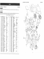
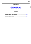
CRAFTSMAN
RAFTSMAN
12"
BAND
SAW
ty attempt
to repair
or replace
\
I37.224120
hen servicing use only CRAFTSMAN
oduct damage.
12'
BAND
\
\
replacement parts. Use of any other parts may create a HAZARD or cause
/
electrical
parts on this band saw may create
a HAZARD
unless
repair is done
SAW
•
.....
\
\
\\
®
/
®\
by a
lalified service technician. Repair service is available at your nearest Sears Service Center,
Order by PART NUMBER, not by key number
®
Key No.
1
2
3
4
5
6
7
8
9
10
PART NUMBER
Description
Size
Qty
3AE00101
3AE00201
3AE00301
3AE00401
3AEOOd01
3AEO0B01
3AEO07Ol
STD522510
3AE009Ot
3AE01O01
Main 0ody
Bearing Hetder
Shaft of lower wheel
Bat_beanng
C _ing
S_'c_g Attachment
Spdng washer
He×,screw
Screw (HeadIess)
Screw {HeadJess)
EBS-12"(C)
EOS-I 2"
E8S-12"(C)
0202ZZ
S-15
EBS-t2"(C)
1t#'
!/4"t
1f4"1t2"
1;4".5/8 _
t
1
1
2
1
1
3
3
2
1
tl
12
13
14
15
16
17
1B
19
20
3AE0t201
3AEO130I
3AE0t401
3AE0150t
3A£01691
3AE01701
3AE01801
STD522500
3AE0200!
Crossheadscrew
Key
Pulley(2 Slot)
V-belt
_owerwheet
_eel prolector
F_a_washerfor1owerwheel
Hexscrew
Upperwheelshafthinge
3/16"'3;8"
5"5*54
EOS-12"(C)¢180"¢163
LA-27
EBSd2"(C)
EBS-12"(PU)
EBS.12"(C)
1f4"5t8"
EBS-1Z
22
23
24
25
26
27
28
29
30
3AE02201
3AE0230I
3AE02401
3AE02501
3AE0260t
3AEQ2701
3AEO2B01
3AEO2901
3AE03001
Springwasher
Hex.Nut
Bracket
Hingerod
Squaretensionadjustingnut
Spring
Guidepostbracket
Flatwasher
SpringWasher
32
33
34
35
36
37
38
39
40
3AE03201
3AE03301
3AE03401
3AE03501
3AE03BOl
3AE03701
3AE0380!
3AEO3901
3AE04®1
42
43
44
45
45
47
48
49
50
Kay No.
72
73
74
75
75
77
78
79
00
81
PART NUMBER
3AE07201
3AE07301
3AE0740t
3AE07501
3AE0760I
3AE07701
3AE07801
3AE07901
3AEOB0Ol
3AE00t01
Description
Idlewheel
Copperbeadng
ShaftelidJewheel
C-dog
Nylonwasher
PIate
Carnagescrew
Flat washer
Nylonnut
Handle
Size
Qty
1
I
1
2
2
1
2
1
1
1
¢12'¢t4'20L
S.12
¢12 2"¢,15'05
EBS-12"(C)
51!8"3/4"
5116"'18
5t!6"
51t5"
2
1
t
1
1
2
t
1
1
83
84
85
86
87
88
89
90
9t
3AE08301
&AE08401
3AEOBd01
3AE08601
3AE08701
3AE0880t
3AEOBg01
3AE0900t
3AE09101
Crosshead screw
Powercord
PowercordW/__ug
Strainreliefbushing
Powercordslorage
C_'ess
head screwWtl washer
Crossheadscrew
Eadhgroundlabel
Teethwasher
3!16"3t8"
2
SJT18"3C'30m751
SJTl_'3C'2.3m75 1
6N-4
2
WA-t4"(C)
2
3t16"'tt2"
2
3/16"'3/8"
2
2
5ram
2
3tB"
3t8"
EOS-12'
EBS-t2"
5t10"
EBS*12"(C)
EBS-12"(C)
5116%18
5V16"
1
1
1
1
1
1
I
3
3
93
94
95
96
97
98
g9
t00
101
3AE0930I
3AEO94Ol
3AE09501
3AE0960t
3AE09701
3AE09801
3AE09901
3AE10101
3AE10101
Hexnut
Swftchplate
CrossheadscrewWtlwasher
Switch
Bracketfor brush
Brush
SeBtappedscrew
Crosshead screwWtl washer
Spdngplate
3t16°
SOTO2m/m
31t6"318"
Upperwheat
Ring
BaI_bearing
Nut
Ftatwasher
Rollednut
Buftediynut
StarknobWtl screw
Guidebar holder
EBS-12"(C)
R-32
8002ZZ
I/2"
5115%23
5t10"
5;t6"
5tlli'2 112"
EBS-1Z(C)
1
2
2
2
1
I
1
t
I
I03
104
t05
108
107
100
109
110
tll
SAE1030t
3AE1040t
3AE1050I
3AE10_01
3AE1070!
3AEt0801
3AE10901
8AEI1001
3AE1110I
Door•lower
Door.upper
Springcliper
Flatwasher
Star knob
Bracketfortn_.qr_ion
Pointer
Springwasher
Crosshead screw
EBS-12"
EBS-12"
EBS-1Z(C)
t/4"'I6
1t4"
EBS-12"(C)
My-2OO0P
3s'18"
3t'10"3f0"
1
I
2
2
2
1
1
1
1
3AE04201
3AEO4301
STD522503
3AE0450t
3AE04601
3AE04701
3AE04001
3AE04901
3AE0500l
Steelptate
Springwasher
Hexscrew
Bearingguidered
Bal!bearing
Ytype btock
Steelpin
Screw(Headless
Screw Headless)
EBS-12(C)
1/4"
1/4°'3t8'
EOS-12"(C)
026ZZ
EBS-t2"
114"25L
1f41"1f2
"
1f#"112"
2
4
4
2
2
2
4
4
1
t12
1!3
114
1t5
1t6
tt7
1t8
t19
120
121
3AEl120t
3AEtt301
STD541031
3AEt1501
3AEl150t
3AEt1701
3AE11801
3AEl1901
3AE12001
3AE12101
Ratwaeher
Hexscrew
Hexnat
Hexecrew
Blade
Table
Tronniondamp shoe
Hexscrew
Trunnion
Sca_e
5f16"18
5/16"'1 1f4"
5;15"
5t16"'3"
g1"'3f8'_0.05
VVA.14"(C)
WA-14
M10%0
WA-I#'
45"
2
2
!
1
1
1
2
2
2
1
52
53
54
55
56
57
58
59
60
3AE052{1t
3AE0530!
3AE05401
3AE05501
3AE05601
3AE05701
3AE05801
3AEOdgOl
3AE0600I
Sled bail
Pointer
Screw(Headless
Springp n
Bladeguard
CrossscrewWiIwasher
Fiatwasher
Hexscrew
StarknobWfl screw
114"
WA.14"(C)
5116"5fi6"
6'20
EBS-tZ
114"3f8"
If4" 15
1/4"'318"
5116"5/0"
1
1
t
1
t
2
4
4
1
123
124
125
120
I27
t28
129
130
13t
3AE12301
3AE1240t
3AE!250t
3AEt260t
3AE12701
3AE12801
3AE12901
3AE1300!
3AE13101
Hexscrew
Spdngpin
Tablepin
Tableinsed
Star knob
Fixtureptatefor duslehute
Springwasher
Hexscrew
Dust_ule
1t4"518"
¢3'10
WA-I4"
WA-14"
WA.14"
EBS-12"(C)
1t4"
114"114"
¢21 If2" WA-14"
6
I
1
1
2
1
3
3
1
61
52
63
64
55
66
07
68
69
70
7I
3AE0610t
3AE06201
3AE06301
3AE06401
3AE0,8501
3AE_O1
3AE0670I
3AE0680t
3AE0690!
3AE07001
ST054t031
132
133
134
3AE1320I
3AE1330t
STD541031
Flatwasher
Hex screw
Nex nut
5/16"t8
5fi6"'2"
5t16"
135
138
137
130
139
140
141
142
3AE13501
3AE13601
3AE13701
3AE13801
3AE!3901
3AE14001
3AE1410t
137224120001
8
4
4
!
1
1
1
1
1
3
1
®
®
®
/
./
\•
/
/
/
\
\
®
\
/
/
\
WA-14"(C)
EBS-12"(C)
3t16"318"
3,'16"'3t8"
2
I
2
1
t
1
2
1
4
/
®
//
Tensionscrew
Lowersupportbracket
Screw(HeadJess)
Fiatwasher
Hexscrew
MotorWtlpowercord
Flatkey
Motor pulley
Screw(Headless)
Flat washer
Hexscrew
EBS-12"
EBS.12"
114"_1f4
*
1f4"16
114"518"
120V60HZ
5"5'32.5
¢50¢'76(2 Slot)
M6'16
5116'18
5118"
1
!
2
2
2
1
!
1
I
4
4
24
Miter gauge assembly
Hex w_ench
Nameplate
Warning label
Motor label
Flat washer
Fiat washer
Manual
WA.14_(C)
3ram
3/8"22"1T
5116"'23
i
\
(_) ./
//
/
/
_e=@-/
\
/
/'\
I
\
+/
¢
/
/
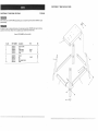
137.224120
CRAFTSMAN
CRAFTSMAN
12" BAND
137.224120
SAW LEG STAND
When servicing use only CRAFTSMAN
product damage+
12" BAND SAW LEG STAND
replacement parts. Use of any other parts may create a HAZARD or cause
10
Any attempt to repair or replace electrical parts on this band saw may create a HAZARD unless repair is done by a
qualified service technician. Repair service is available at your nearest Sears Service Center.
Order by PART NUMBER, not by key number
Key No.
PART NUMBER
Description
1
2
3
4
5
3AD30101
3AD30201
3AD30301
3AD3040!
3AD30501
Stand Top Plate
Leg
Lower bracket
Lower bracket
Screw
.............................................................................................................
6
7
8
9
10
3AD30601
3AD30701
3AD31001
3AD31101
3AD31201
...................................................................................................................................
Size
1
4
2
2
32
(short)
(long)
+...............................................................
Washer
Nut
Pad
Miter gauge storage
Screw
Qty
+..................................
1/4x5/8
32
32
4
1
2
_,+-+ ........................................................................
8