1
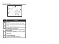
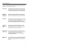
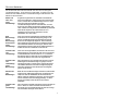
mlpn 2348 cover.qxd
9/21/2004
2:57 PM
Page 1
METROLOGIC INSTRUMENTS, INC.
IS4220 ScanGlove
Laser Bar Code Scanner
Installation and User’s Guide
®
LOCATIONS
CORPORATE HEADQUARTERS
NORTH AMERICA
EUROPEAN, MIDDLE EAST & AFRICAN
HEADQUARTERS
USA, NEW JERSEY
Metrologic Instruments, Inc.
Tel: 1-800-ID-METRO Fax: 856-228-6673
Email: [email protected]
GERMANY, MUNICH
Metrologic Instruments GmbH
Tel: 49-89-89019-0 Fax: 49-89-89019-200
Email: [email protected]
SOUTH AMERICA, BRAZIL SÃO PAULO
Metrologic do Brasil Ltda.
Tel: 55-11-5182-8226 Fax: 55-11-5182-8315
Email: [email protected]
GERMANY, MUNICH
Metrologic Instruments GmbH
Tel: 49-89-89019-0 Fax: 49-89-89019-200
Email: [email protected]
SOUTH AMERICA, OUTSIDE BRAZIL SÃO PAULO
Metrologic South America
Tel: 55-11-5182-7273 Fax: 55-11-5182-7198
Email: [email protected]
ITALY, BOLOGNA
Metrologic Instruments Italia srl
Tel: +39 0 51 6511978 Fax: +39 0 51 6521337
Email: [email protected]
ASIA, SINGAPORE
Metrologic Asia (Pte) Ltd
Tel: 65-6842-7155 Fax: 65-6842-7166
Email: [email protected]
FRANCE, PARIS
Metrologic Eria France SA
Tel: +33 (0) 1 48.63.78.78
Fax: +33 (0) 1 48.63.24.94
Email: [email protected]
CHINA, SUZHOU
Metro Technologies Co., Ltd.
Tel: 86-512-62572511 Fax: 86-512-62571517
Email: [email protected]
SPAIN, MADRID
Metrologic Eria Ibérica, SL
Tel: +34 913 272 400 Fax: +34 913 273 829
Email: [email protected]
Metro Sales Office
Tel: 86-512-67622550 Fax: 86-512-67622560
Email: [email protected]
Metrologic Europe Repair Center (MERC)
Metrologic Eria Ibérica, SL
Tel: +34 913 751 249 Fax: +34 913 270 437
JAPAN, TOKYO
Metrologic Japan Co., Ltd.
Tel: 81-03-3839-8511 Fax: 81-03-3839-8519
Email: [email protected]
UNITED KINGDOM, BASINGSTOKE
Metrologic Instruments UK Limited
Tel: +44 (0) 1256 365900
Fax: +44 (0) 1256 365955
Email: [email protected]
RUSSIA, MOSCOW
Metrologic Russia
Tel: +7 095 730 7424 Fax: +7 095 730 7425
Email: [email protected]
Copyright
© 2004 by Metrologic Instruments, Inc. All rights reserved. No part of this work may be reproduced,
transmitted, or stored in any form or by any means without prior written consent, except by reviewer, who
may quote brief passages in a review, or provided for in the Copyright Act of 1976.
Products and brand names mentioned in this document are trademarks of their respective companies.
ii
TABLE OF CONTENTS
Introduction .......................................................................................................... 1
Scanner and Accessories .................................................................................... 1
Scanner Installation.............................................................................................. 2
Scanner Configuration to the Host System .......................................................... 3
Parts of the Scanner ............................................................................................ 4
Visual Indicators................................................................................................... 5
Audible Indicators................................................................................................. 9
Labels................................................................................................................. 10
Maintenance....................................................................................................... 10
Infrared (IR) Object Sensor ................................................................................ 11
Scan Field .......................................................................................................... 12
Specifications ..................................................................................................... 13
Default Settings .................................................................................................. 14
Troubleshooting Guide ....................................................................................... 19
Limited Warranty................................................................................................ 20
Notices ............................................................................................................... 21
Patents ............................................................................................................... 23
Index................................................................................................................... 24
iii
INTRODUCTION
The IS4220 ScanGlove® is a fully automatic single-line laser barcode scanner.
It is designed to be used as a “hands-free” wearable scanner or a stationary
desktop scanner.
Every ScanGlove is equipped with ScanQuest®, a patented activation technology
that allows the scanner to read bar codes automatically as the operator presents
the bar code to the scanner. Additional features include; 52 scan lines a
second, short or long range activation and two universal glove sizes with left and
right-hand capabilities.
The IS4220 has built in decoding for applications that use a RS232, Keyboard
Wedge, Stand Alone Keyboard, Light Pen Emulation, or USB communication
interface. For additional information on other system interfaces call please call a
Metrologic Customer Service Representative at 1-800-ID-METRO.
SCANGLOVE MODEL NO.
INTERFACE
IS4220-07
USB Keyboard
IS4220-08
USB POS
IS4220-14
RS232
IS4220-15
Light Pen Emulation
IS4220-17
PC Keyboard Wedge and Stand Alone Keyboard
IS4220-41
Full RS232 and Light Pen Emulation
SCANNER AND ACCESSORIES
PART NUMBER
IS4220
DESCRIPTION
IS4220 Laser Scanner
00-02348
Installation and User’s Guide
00-02343
Programming Guide
00-02044
Programming Addendum (USB Models Only)
45-45455
Black Adjustable Glove
If any item is missing or to order additional items, contact the dealer, distributor or call
Metrologic’s Customer Service Department at 1-800-ID-METRO or 1-800-436-3876.
1
SCANNER INSTALLATION
1.
Turn off power to the host system.
2.
Connect the communication cable to the proper port on the host device.
3.
Turn on power to the host system.
When the IS4220 first receives power, the red LED will flash, the
green LED will flash, and then the scanner will beep once.
Caution:
To maintain compliance with applicable standards, all circuits connected
to the scanner must meet the requirements for SELV (Safety Extra Low
Voltage) according to EN 60950.
To maintain compliance with standard CSA C22.2 No. 950/UL 1950 and
norm EN 60950, the power source should meet applicable performance
requirements for a limited power source.
To maintain compliance with federal regulations 21 CFR, Part 1040.10,
section (f)(6) the scanner must be plugged into an electrical outlet with a
switch accessible to the user or be powered by a host system containing
a switch that will disable power to the scanner.
2
SCANNER CONFIGURATION TO THE HOST SYSTEM
The IS4220 is shipped from the factory pre-programmed to a set of default
parameters. It may be necessary to change the default parameters to match the
host system’s requirements or to enable additional scanner functions. For a list
of possible parameter settings, refer to the Default Settings section of this guide.
Important notes for the -07 and -08, IS4220 USB Interfaces.
The IS4220-07 and the IS4220-08 are pre-programmed for USB
Emulation before leaving the factory. If the recall defaults bar code is
scanned the unit must be re-programmed for USB Emulation before
enabling or disabling any additional features documented in the
programming guide (MLPN 00-02343).
To re-program the unit for USB Keyboard Emulation or USB POS
Emulation refer to the IS4220 USB Addendum (MLPN 00-02044)
for the IS4220 Programming Guide.
To modify the scanner’s default parameters follow the steps below using the bar
codes located in the programming guide (MLPN 00-02343).
1.
Scan the ENTER PROGRAM MODE bar code to enter programming mode. The
scanner will beep three times.
2.
Scan the bar code(s) for the desired parameter(s). The scanner will beep
once.
3.
Scan the EXIT PROGRAM MODE bar code to exit and save the new parameter
settings. The scanner will beep three times.
If during programming there is a need to return the scanner to the
original factory settings, scan the recall defaults bar code in the
programming guide. All settings selected during that session or any
previous sessions are discarded when you scan the recall defaults
code.
Please read the warning above for the IS4220-07 and -08 models
before using the recall defaults bar code.
3
PARTS OF THE SCANNER
Figure 1. Scanner Parts
Item
No.
Description
Green LED
When a bar code is read successfully the green LED will flash.
Red LED
When the red LED is illuminated, the laser is on.
Red Output Window (Laser Aperture)
Infrared Sensor (IR)
If a specified time has elapsed without any scanning, the unit will
enter a “standby” mode. To reactivate the unit, place an object in
front of the IR sensor. The red LED will turn on when the scanner
is ready to scan.
Communication/Power Cable
This cable’s termination is application dependent.
4
VISUAL INDICATORS
There is a red and a green LED located on the top of the scanner. When the
scanner is on, the flashing or constant illumination of the LEDs indicates the
status of the current scan and the scanner.
No Red LED
Illumination of the LEDs will not occur if the scanner has
remained dormant for a specified time and the scanner is
not receiving power from the host. To reactivate the unit,
direct the output window up then down toward the object.
Red Flash;
Green Flash;
Steady Red
When the scanner first receives power, the red LED will
flash, followed by the green LED, and then the unit will
beep once. The red LED will stay on after it flashes once.
Steady Red
When the laser is on, the red LED will be on. This occurs
when an object is detected in the scan field. If the scanner
cannot detect a bar code within approximately 2.5
seconds, the unit will go into a standby mode and the red
LED will shut off indicating that the laser is no longer on.
Steady Red
LED; Green
Flash
When the scanner successfully reads a bar code, the
green LED will flash and the unit will beep once. If the
green LED does not flash or the scanner does not beep,
then the bar code was not successfully read.
Repetitive Red
LED Flashing
When the red LED flashes several times while it rests
upon a stationary surface, then an object is within the scan
field and is activating the IR sensor repetitively.
To eliminate this disturbance, direct the scan window
toward a different location.
Steady Green
LED
After a successful scan, the scanner transmits the data to
the host device. When the host is not ready to receive the
information, the green LED will remain on until data can
transmit.
5
SIGNAUX OPTIQUES
Sur la partie supérieure du scanner se trouvent une diode LED rouge et une
diode LED verte. Quand le scanner est sous tension, les diodes rouge et verte
clignotantes ou allumées vous informent sur l'état de palpage et de scanner.
Ni la diode
rouge, ni la
diode verte
n'est allumée
Il existe deux raisons possibles pour que les diodes ne
s'allu-ment pas. Si le scanner ne reçoit pas d'énergie de
l'ordinateur PC, les diodes ne s'allument pas. Quand le
scanner reçoit de l'énergie et ne s'allume cependant pas,
le scanner est resté pendant une certaine période sans
être utilisé et le laser et lemoteur sont désactivés. Pour
réactiver l'unité, déplacer un objet devant le palpeur
infrarouge ou prendre le scanner et diriger la fenêtre de
palpage vers le bas.
Diode rouge
clignotante;
diode verte
clignotante;
diode rouge
reste allumée
Quand le scanner reçoit pour la première fois de l'énergie,
la diode rouge se met d'abord à clignoter, puis la diode
verte. Ensuite, le scanner émet un bip sonore unique. Une
fois cette séquence de démarrage effectuée, la diode
rouge reste allumée pendant un certain temps indiquant
que le laser est en service. Quand le scanner ne détecte
aucun objet, la diode rouge et le laser s'éteignent.
Diode rouge
reste allumée
Quand le laser est activé, la diode rouge s'allume
également. C'est par exemple le cas quand un objet se
trouve devant la fenêtre de palpage. Si, en l'espace de 2,
5 secondes, aucun code barres n'est détecté, la diode
rouge s'éteint, ce qui signifie que le laser est désactivé.
Diode rouge
reste allumée;
diode verte
clignotante
Clignotement
répété de la
diode rouge
Diode verte
reste allumée
6
Après lecture avec succès d'un code barres par le
scanner, la diode verte se met à clignoter, suivie d'un bip
sonore unique. Si la diode verte ne clignote pas ou quand
aucun bip sonore n'est émis, cela signifie que le code
barres n'a pas pu être lu avec succès.
Quand la diode rouge clignote plusieurs fois pendant que
l'appareil repose sur une surface non déplacée, un objet
activant le palpeur infrarouge se trouve devant la fenêtre
de palpage. Ceci peut se produire même quand le
scanner se trouve sur une table ou un reposoir. Pour
éliminer ce défaut, positionner le scanner de façon
différente.
Une fois le palpage effectué avec succès, le scanner
transmetles donnéesà l'ordinateur PC. Si ce dernier n'est
pas prêt à recevoir les données, la diode verte du scanner
s'allume jusqu'à ce que les donnés puissent être
transmises.
OPTISCHE ANZEIGEN
Auf der Oberseite des Scanners befinden sich eine rote und eine grüne
Leuchtdiodenanzeige. Ist der Scanner eingeschaltet, so geben Ihnen die
blinkenden oder feststehenden Leuchtdiodenanzeigen Aufschluß über den
Abtast und Scannerstatus.
Weder rote
oder noch
grüne
Leuchtanzeige
Es gibt zwei mögliche Gründe, weshalb die Leuchtdiodenan
zeigen nicht aufleuchten. Bekommt der Scanner keine Energie
vom PC, leuchten die Leuchtdiodenanzeigen nicht auf. Wenn
der Scanner jedoch Energie bekommt und die
Leuchtdiodenanzeigen dennoch nicht aufleuchten, so ist der
Scanner für einen bestimmten Zeitraum untätig geblieben, und
Laser und Motor sind abgeschaltet. Zur Reaktivierung der Einheit
sollten Sie ein Objekt vor dem Infrarot Sensor hin und
herbewegen oder den Scanner aufnehmen und das
Abtastfenster nach unten richten.
Rote
Blinkanzeige;
Grüne
Blinkanzeige;
feststehende
grüne
Leuchtanzeige
Wenn dem Scanner erstmalig Energie zugeführt wird, blinkt
zunächst die rote Leuchtdiodenanzeige auf, gefolgt von der
grünen Leuchtdiodenanzeige,und anschließend sendet der
Scanner ein einmaliges Piep-Signal aus. Nach Ausführung
dieser Startsequenz leuchtet die rote Leuchtdiodenanzeige für
einen bestimmten Zeitraum auf und zeigt an, daß der Laser
eingeschaltet ist. Wird dem Scanner kein Objekt präsentiert, so
schalten sich die rote Leuchtdiode und der Laser ab.
Feststehende
rote
Leuchtanzeige
Wenn der Laser eingeschaltet ist, leuchtet auch die rote Leuchtdiodenanzeige auf. Dies ist dann der Fall, wenn sich ein Objekt
im Abtastfeld befindet. Wird innerhalb von ca. 2,5 Sekunden
kein Barcode erfaßt, so erlischt die rote Leuchtdiodenanzeige,
was bedeutet, daß der Laser nicht mehr eingeschaltet ist.
Feststehende
rote
Leuchtanzeige;
grüne
Blinkanzeige
Nach erfolgreichem Lesen eines Barcodes durch den Scanner
blinkt die grüneLeuchtdiodenanzeige auf, gefolgt von einem
einmaligen Piep-Signal. Falls die grüne Leuchtdiodenanzeige
nicht aufblinkt oder der Scanner kein einmaliges Piep-Signal
aussendet, bedeutet dies, daß der Barcode nicht erfolgreich
gelesen werden konnte.
Wiederholte
rote
Blinkanzeigen
Blinkt die rote Leuchtdiodenanzeige mehrmals auf, während das
Gerät auf einer nichtbewegten Fläche liegt, so befindet sich ein
Objekt inner halb des Abtastfeldes,das den Infrarot-Sensor
aktiviert. Dies kann selbst dann vorkommen, wenn der Scanner
auf dem Ladentisch oder dem Ablagegestell liegt. Um diese
Störung zu beseitigen, sollten Sie den Scanner anders
positionieren.
Feststehende
grüne
Leuchtanzeige
Nach erfolgreichem Abtasten überträgt der Scanner die Daten an
den PC. Ist der PC nicht zur Annahme der Daten bereit, so
leuchtet die grüne Leuchtdiodenanzeige des Scanners solange
auf, bis die Daten übertragen werden können.
7
SEGNALI OTTICI
Sulla parte superiore dello scanner si trovano due diodi luminosi: uno rosso e
uno verde. Quando lo scanner è inserito, i diodi luminosi, che possono o essere
accesi in continuazione o lampeggiare, Vi informano sullo stato della scansione
e dell’apparecchio.
Né il diodo
luminoso rosso
né quello verde
sono accesi
Vi sono due possibili cause se i diodi luminosi non sono
accesi. Se lo scanner non viene alimentato dal PC i diodi
luminosi non sono accesi. Se invece lo scanner è
alimentato e ciònonostante Idiodi luminosi non sono accesi,
lo scanner è rimasto disattivato per un determinato periodo
e laser e motore sono spenti. Per riattivare l’unità
dovreste muovere un oggetto davanti al sensore a
infrarossi oppure prendere lo scanner e rivolgere il
finestrino di scansione verso il basso.
Il diodo luminoso
rosso lampeggia;
il diodo luminoso
verde lampeggia;
il diodo luminoso
verde è acceso
Quando lo scanner viene alimentato per la prima volta,
lampeggia dapprima il diodo luminoso rosso e quindi
quello verde. Poi lo scanner emette un unico segnale
beep Dopo l’esecuzione di questa sequenza di avvio il
diodo luminoso rosso si accende per un determinato
periodo ed indica che il laser è inserito. Se allo scanner
non viene presentato nessun o ggetto, il diodo luminoso
rosso e il laser si spengono.
Il diodo
Quando il laser è attivato, è acceso anche il diodo
luminoso rosso luminoso rosso. Questo si ha quando un oggetto si trova
nella zona di scansione. Se entro ca. 2, 5 secondi non
è acceso
viene registrato nessun codice a barre, il diodo luminoso
rosso si spegne; ciò significa che il laser non è più attivato.
Il diodo luminoso
rosso è acceso; il
diodo luminoso
verde lampeggia
Dopo la lettura riuscita di un codice a barre da parte dello scanner
il diodo luminoso verde lampeggia e quindi viene emesso un unico
segnale beep. Se il diodo luminoso verde non lampeggia oppure
lo scanner non emette un segnale beep, ciò significa che la lettura
del codice a barre non è riuscita.
Il diodo luminoso Dopo la scansione riuscita lo scanner trasmette i dati al
verde è acceso
PC. Se il PC non è pronto per accettare i dati, il diodo
luminoso verde dello scanner è acceso fino a che i dati
possono essere trasmessi.
Il diodo
luminoso rosso
lampeggia
ripetutamente
8
Se il diodo luminoso rosso lampeggia ripetutamente
mentre l’app-arecchio si trova su una superficie che non si
muove, vi è un oggetto all’ interno della zona di scansione
che attiva il sensore a infrarossi. Ciò può essere
addirittura il caso quando lo scanner si trova sul banco
oppure nel suo supporto. Per eliminare questa anomalia
basta cambiare la posizione dello scanner.
AUDIBLE INDICATORS
The scanner provides sounds to signal certain conditions. To change the
volume (four settings are available) or turn the beeper off, refer to Beeper Tones
in the Programming Guide.
One Beep
When the scanner first receives power, the red LED will
flash, followed by the green LED, and then the scanner
will beep once. After the scanner performs this start-up
sequence, the scanner is ready to scan.
When the scanner successfully reads a bar code, the
green light will flash and the unit will beep once. If the
green LED does not flash or the scanner does not beep,
then the bar code read is not successful.
Razzberry Tone
If, upon power up, the scanner emits a razzberry tone the
scanner has failed diagnostics.
The scanner can be programmed to emit a
razzberry tone when the timeout occurs during
communication between the host and scanner.
Refer to Audible Indicators for Communication
Timeouts the Programming Guide.
Three Beeps
When entering program mode, the green LED will flash
three times while the scanner simultaneously beeps
three times. When exiting program mode, the same
visual and audible indications will occur. After this
sequence is completed, the red LED will turn off.
The scanner can be programmed to emit three
beeps when the timeout occurs during
communication between the host and scanner.
Refer to Audible Indicators for Communication
Timeouts the Programming Guide.
9
LABELS
Each IS4220 has a serial number label and a laser class label on the bottom of
the unit. These labels provide important information like; date and location of
manufacture, model number, serial number, caution statements and laser class.
There is also text molded into the top of the case near the window that says,
“AVOID EXPOSURE - laser light emitted from this aperture”. The following
Figure shows examples of these labels*.
Figure 2. Caution and Serial Number Labels*
* Labels not shown to scale.
MAINTENANCE
Smudges and dirt can interfere with the proper scanning of a bar code.
Therefore, the output window will need occasional cleaning.
10
1.
Spray glass cleaner onto lint free, non-abrasive cleaning cloth.
2.
Gently wipe the output window.
INFRARED (IR) OBJECT SENSOR
An infrared (IR) device located behind the window initiates the scanning process.
The IR sensor is active as long as power is applied to the unit. When the IR
sensor detects an object, the green LED will flash. When the laser decodes a
bar code, the scanner transmits the data to the host system and emits a beep to
show that decoding is complete. The IR sensor range can be programmed for
two ranges.
Short Range Activation
The IR signal initiates the scan process if it senses an object anywhere from the
face of the window out to approximately 4" to 7".
Long Range Activation
The IR signal initiates the scan process if it senses an object anywhere from the
face of the window out to approximately 9" to 13".
If the object is removed from the field during the scanning process, the laser
turns off and the scanner re-enters "standby" mode. However, if the object stays
in the field, the laser remains on for up to 2.5 seconds trying to detect another
bar code. If the scanner does not detect a bar code, the scanner re-enters
"standby" mode. To reactivate the scanning sequence, remove the object and
present another.
If the same symbol stays in the field after a successful scan, the laser stays on
for approximately 7.5 seconds and then turns off. This prevents unintentional
reads of the same bar code. To read the same symbol more than once, remove
the object from the scan field for approximately 1 second and then present the
symbol again.
11
Scan Field
The depth of field for the scanner is 12.7 mm to 203 mm (.5" to 8") from the face of
the output window for .33 (13 mil) Bar Codes.
Figure 3. Scan Field for .33 (13 mil) Bar Codes
Specifications subject to change without notice.
12
SPECIFICATIONS
IS4220 SPECIFICATIONS
OPERATIONAL
Light Source:
650 nm VLD
Depth of Field:
12.7 mm to 203 mm (.5" to 8") for .33 (13 mil) bar code
Width of Scan Field:
28.6 mm (1.125”) @ face; 102 mm (4”) @ 76.2 mm (3”)
Scan Speed:
Scan Pattern:
Min Bar Width:
52 scans lines per second
Single scan line
0.173 mm (6.8 mil)
Decode Capability:
Autodiscriminates all standard bar codes; for other
symbologies call a Metrologic representative
System Interfaces:
RS232, Light Pen Emulation, PC Keyboard Wedge, Stand
Alone Keyboard, USB (low speed)
Print Contrast:
Number of
Characters Read:
Roll, Pitch, Yaw:
Beeper Operation:
Indicators (LED):
35% minimum reflectance difference
up to 80 data characters (Maximum number will vary based
on symbology and density)
42°, 68°, 52°
3 tones or no beep
red = laser on, ready to scan
green = good read, decoding
MECHANICAL
Length x Width x Height:
Weight:
Cable Termination:
70 mm x 49 mm x 24 mm (2.75" x 1.94” x 0.94”)
105 grams (3.7 oz.)
Application Dependent
ELECTRICAL
Input Voltage:
5VDC ± 0.25V
Power:
0.75 W
Operating Current:
135 mA
DC Transformers:
Laser Class 2:
EMC:
Class 2; 5VDC @ 300 mA
EN 60825-1:1993+A1:1997+A2:2001
EN 60825-1:1994+A11:1996+A2:2001
FCC, ICES-003 & EN 55022 Class A
ENVIRONMENTAL
Operating Temperature:
Storage temperature:
Humidity:
Light Levels:
Shock:
Contaminants:
Ventilation:
-20°C to 50°C (-4°F to 122°F)
-40°C to 70°C (-40°F to 158°F)
5% to 95% relative humidity, non-condensing
Up to 4842 Lux (450 footcandles)
Designed to withstand 1.5 m (5’) drops
Sealed to resist airborne particulate contaminants
None required
Specifications subject to change without notice.
13
DEFAULT SETTINGS
Many functions of the scanner can be "programmed", that is enabled or
disabled. The scanner is shipped from the factory programmed to a set of
default conditions. All factory default parameters have an asterisk ( * ) in the
default column of the charts on the following pages . If an asterisk is not in the
default column then the setting is off or disabled by default. Every interface does
not support every parameter. If the interface supports a parameter listed in the
charts on the following pages, a check mark ( ) will appear.
PARAMETER
Enter Program Mode After Any Scan
DEFAULT
*
Enter Program Mode Only on
First Scan
Short Range Activation
Long Range Activation
*
Normal Scan
*
Pulsing Scan
Custom Scan
Short Same Symbol Rescan
Long Same Symbol Rescan
*
Alternate Beeper Tone 1
Alternate Beeper Tone 2
*
Alternate Beeper Tone 3
No Beeper Tone
Two Second Timeout
No Two Second Timeout
*
Razzberry Tone on Timeout
No Tone on Timeout
*
Three Beeps on Timeout
Beep Before Transmit
*
Beep After Transmit
Baud Rate
Parity
9600
Space
8 Data Bits
7 Data Bits
*
RTS/CTS
Character RTS/CTS
Message RTS/CTS
14
*
RS232
LIGHT
PEN
KEYBOARD
WEDGE
USB
DEFAULT SETTINGS
PARAMETER
DEFAULT
RS232
LIGHT
PEN
KEYBOARD
WEDGE
USB
ACK/NAK
XON/XOFF
*
No Intercharacter Delay
1 Millisecond Intercharacter Delay
5 Millisecond Intercharacter Delay
10 Millisecond Intercharacter Delay
25 Millisecond Intercharacter Delay
100 Millisecond Intercharacter Delay
DTR Input
DTR Scan Disable
“DE” Disable Command
LRC Calc+ Transmit RS232
Start LRC on first RS232 Byte
Start LRC on Second RS232 Byte
*
Carriage Return
*
Line Feed
*
STX Prefix
ETX Suffix
Tab Prefix
Tab Suffix
Prefix ID for UPC/EAN
Suffix ID for UPC/EAN
Bars High
*
Spaces High
Transmit as Scanned
Transmit as Code 39
*
Poll Light Pen 5 Volts
No Poll Light Pen
*
Reverse Polarity Idle for Light Pen
UPC
*
EAN
*
Full ASCII code 39
Code 39
*
Codabar
Code 128
*
Code 93
*
Interleaved 2 of 5 (ITF)
*
Code 11
15
DEFAULT SETTINGS
PARAMETER
DEFAULT
Hong Kong Matrix 2 of 5
Airline 2 of 5
Minimum 1 Character Code Length
Minimum 3 Character Code Length
*
Minimum 6 Character Code Length
Set Minimum Character Length
Set Character Lock Length
Transmit UPC-A Number Sys
*
UPC-A Check Digit Transmit
*
Convert UPC-A to EAN-13
Expand UPC-E
UPC-E Check Digit Transmit
UPC-E Leading 0 Transmit
EAN-8 Check Digit Transmit
*
EAN-13 Check Digit Transmit
Convert EAN-8 to EAN-13
“$” Prefix ID for UPC/EAN
2 Digit Supps (Scan)
5 Digit Supps (Scan)
Bookland (Scan)
Supplement Required
Bookland to ISNB
Transmit ISNB CD
Mod 43 Check Digit Code 39
Transmit Mod 43 Check Digit Code 39
*
Transmit Start/Stop Code 39
CLSI Editing (Enable)
ITF Check Digit
Transmit MOD 10 ITF Check Digit
I 2 of 5 Symbol Lengths
ISBN Reformatting
Coupon Code 128
16
Variable
RS232
LIGHT
PEN
KEYBOARD
WEDGE
USB
DEFAULT SETTINGS
PARAMETER
DEFAULT
RS232
LIGHT
PEN
KEYBOARD
WEDGE
USB
]C1 Transmit Coupon C128
Coupon 128 Group Separator
Italian Pharmaceutial
Codabar Start and Stop Class
ITF Minimum Symbol Length Test
Matrix 2 of 5 Check Digit
Hong Kong Matrix 2 of 5
MSI - Plessey Test of Check Digit
*
Enable MSI - Plessey
Mod 10 Check Digit
Enable MSI - Plessey
Mod 10/10 Check Digit
Transmit MSI - Plessey Check Digit
*
UK Plessey
UK Plessey Check Digit
UK Plessey Special Format
A to X conversion (UK)
Scan Count Test Mode
Scanability Test Mode
Normal Scan/Operating Test Mode
Transmit Scanner Parameters Test Mode
Code ID
Sanyo 635 ECR Protocol
Post Software ID Characters
“Newcode” Mode A
“Newcode” Mode B
BIO DATA Mode
Golden Bountiful Formatting
Intermec Polling Mode D
(limited function)
Enable Sineko Mode
Enable Caps Lock Mode
(for MI951 keyboard wedge)
Enable French Wyse 120 PC Term
Rochford Tompson Mode
17
DEFAULT SETTINGS
PARAMETER
DEFAULT
RTS Counter Toggle
Beep on BEL RS232
Bancorner Mode
FedEX parsing
Retransmit of Same Code
1st Programmable Prefix ID
2nd Programmable Prefix ID
1st Programmable Suffix ID
2nd Programmable Suffix ID
Clear all Programmable Prefixes and
Suffixes
SNI Beetle Mode
ATKeyboard
*
Type XT Keyboard
Type PS2 Keyboard
USA Keyboard
*
Belgium Keyboard
France Keyboard
Germany Keyboard
Spain Keyboard
Italy Keyboard
UK Keyboard
IBM KDB4700 Financial Keyboard
Alt Mode
Auto Detection or Caps Lock
User-Defined Caps Lock
F0H Break Code Transmission
*
800 Microsecond Delay-Enter Scan Code
*
15 Millisecond Delay-Enter Scan Code
7-5 Millisecond Delay-Enter Scan
Code
18
RS232
LIGHT
PEN
KEYBOARD
WEDGE
USB
TROUBLESHOOTING GUIDE
The following guide is for reference purposes only. Contact a Metrologic
representative at 1-800-ID-METRO or 1-800-436-3876 to preserve the limited
warranty terms on page 20.
SYMPTOMS
POSSIBLE CAUSE(S)
SOLUTION
No Power is being
supplied to the
scanner
Make sure the cable is
plugged into the host.
Check the host system’s
power cable, the outlet and
power strip.
No LEDs, beep and
there is no visible laser
No power is being
supplied from the
USB port.
The IS4220 requests
100mA from the USB port.
If the USB port cannot
supply this, a notification
window will appear on the
screen.
After scanning a bar
code, the Red and
Green LEDs are on,
but no data is being
transmitted to the host.
The scanner is not
programmed properly
for communication
with the host.
Re-program the scanner
using the appropriate codes
for your scanner model.
No LEDs, beep and
there is no visible laser
USB Keyboard Emulation
After scanning a bar
code, the scanner
beeps, but the
characters appear
incorrectly in your
application.
The scanner powers
up, but does not scan
and/or beep.
The scanner is not
programmed
correctly.
The incorrect country
has been selected.
The scanner is trying
to scan a particular
bar code symbology
that is not enabled
Re-program the scanner
using the appropriate codes
for your scanner model.
Verify that the type of bar
code being read is
enabled.
19
LIMITED W ARRANTY
The IS4220 ScanGlove® scanners are manufactured by Metrologic at its Blackwood, New
Jersey, U.S.A. facility. The IS4220 scanners have a two (2) year limited warranty from the
date of manufacture. Metrologic warrants and represents that all IS4220 scanners are free
of all defects in material, workmanship and design, and have been produced and labeled in
compliance with all applicable U.S. Federal, state and local laws, regulations and
ordinances pertaining to their production and labeling.
This warranty is limited to repair, replacement of Product or refund of Product price at the
sole discretion of Metrologic. Faulty equipment must be returned to the Metrologic facility in
Blackwood, New Jersey, U.S.A. or Puchheim, Germany. To do this, contact Metrologic’s
Customer Service/Repair Department to obtain a Returned Material Authorization (RMA)
number.
In the event that it is determined the equipment failure is covered under this warranty,
Metrologic shall, at its sole option, repair the Product or replace the Product with a
functionally equivalent unit and return such repaired or replaced Product without charge for
service or return freight, whether distributor, dealer/reseller, or retail consumer, or refund
an amount equal to the original purchase price.
This limited warranty does not extend to any Product which, in the sole judgement of
Metrologic, has been subjected to abuse, misuse, neglect, improper installation or
accident, nor any damage due to use or misuse produced from integration of the Product
into any mechanical, electrical or computer system. The warranty is void if the case of
Product is opened by anyone other than Metrologic’s repair department or authorized
repair centers.
THIS LIMITED WARRANTY, EXCEPT AS TO TITLE, IS IN LIEU OF ALL OTHER
WARRANTIES OR GUARANTEES, EITHER EXPRESS OR IMPLIED, AND
SPECIFICALLY EXCLUDES, WITHOUT LIMITATION, WARRANTIES OF
MERCHANTABILITY AND FITNESS FOR A PARTICULAR PURPOSE UNDER THE
UNIFORM COMMERCIAL CODE, OR ARISING OUT OF CUSTOM OR CONDUCT. THE
AND REMEDIES PROVIDED HEREIN ARE EXCLUSIVE AND IN LIEU OF ANY OTHER
RIGHTS OR REMEDIES. IN NO EVENT SHALL METROLOGIC BE LIABLE FOR ANY
INDIRECT OR CONSEQUENTIAL DAMAGES, INCIDENTAL DAMAGES, DAMAGES TO
PERSON OR PROPERTY, OR EFFECT ON BUSINESS OR PROPERTY, OR OTHER
DAMAGES OR EXPENSES DUE DIRECTLY OR INDIRECTLY TO THE PRODUCT,
EXCEPT AS STATED IN THIS WARRANTY. IN NO EVENT SHALL ANY LIABILITY OF
METROLOGIC EXCEED THE ACTUAL AMOUNT PAID TO METROLOGIC FOR THE
PRODUCT. METROLOGIC RESERVES THE RIGHT TO MAKE ANY CHANGES TO THE
PRODUCT DESCRIBED HEREIN.
CORPORATE HEADQUARTERS
Metrologic Instruments, Inc.
90 Coles Road
Blackwood, NJ 08012-4683
Customer Service: 1-800-ID-METRO
Tel: 856-228-8100
Fax: 856-228-6673
Email: [email protected]
Website: www.metrologic.com
GERMANY
Metrologic Instruments GmbH
Dornierstrasse 2
82178 Puchheim b.
Munich, Germany
20
Tel: 49-89-89019-0
Fax: 49-89-89019-200
Email: [email protected]
NOTICES
Notice
This equipment has been tested and found to comply with limits for a Class A digital device, pursuant to
part 15 of the FCC Rules. These limits are designed to provide reasonable protection against harmful
interference when the equipment is operated in a commercial environment. This equipment generates,
uses and can radiate radio frequency energy and, if not installed and used in accordance with the
instruction manual, may cause harmful interference to radio communications. Operation of this
equipment in a residential area is likely to cause harmful interference, in which case the user will be
required to correct the interference at his own expense. Any unauthorized changes or modifications to
this equipment could void the user’s authority to operate this device.
This device complies with part 15 of the FCC Rules. Operation is subject to the following two conditions:
(1) This device may not cause harmful interference, and (2) this device must accept any interference
received, including interference that may cause undesired operation.
Notice
This Class A digital apparatus complies with Canadian ICES-003.
Remarque
Cet appareil numérique de la classe A est conforme à la norme NMB-003 du Canada.
Caution
Use of controls or adjustments or performance of procedures other than those specified herein may result
in hazardous laser light exposure. Under no circumstances should the customer attempt to service the
laser scanner. Never attempt to look at the laser beam, even if the scanner appears to be nonfunctional.
Never open the scanner in an attempt to look into the device. Doing so could result in hazardous laser light
exposure. The use of optical instruments with the laser equipment will increase eye hazard.
Atención
La modificación de los procedimientos, o la utilización de controles o ajustes distintos de los
especificados aquí, pueden provocar una luz de láser peligrosa. Bajo ninguna circunstancia el usuario
deberá realizar el mantenimiento del láser del escáner. Ni intentar mirar al haz del láser incluso cuando
este no esté operativo. Tampoco deberá abrir el escáner para examinar el aparato. El hacerlo puede
conllevar una exposición peligrosa a la luz de láser. El uso de instrumentos ópticos con el equipo láser
puede incrementar el riesgo para la vista.
Attention
L'emploi de commandes, réglages ou procédés autres que ceux décrits ici peut entraîner de graves
irradiations. Le client ne doit en aucun cas essayer d'entretenir lui-même le scanner ou le laser. Ne
regardez jamais directement le rayon laser, même si vous croyez que le scanner est inactif. N'ouvrez
jamais le scanner pour regarder dans l'appareil. Ce faisant, vous vous exposez à une rayonnement laser
qú êst hazardous. L'emploi d'appareils optiques avec cet équipement laser augmente le risque
d'endommagement de la vision.
Achtung
Die Verwendung anderer als der hier beschriebenen Steuerungen, Einstellungen oder Verfahren kann
eine gefährliche Laserstrahlung hervorrufen. Der Kunde sollte unter keinen Umständen versuchen, den
Laser-Scanner selbst zu warten. Sehen Sie niemals in den Laserstrahl, selbst wenn Sie glauben, daß der
Scanner nicht aktiv ist. Öffnen Sie niemals den Scanner, um in das Gerät hineinzusehen. Wenn Sie dies
tun, können Sie sich einer gefährlichen Laserstrahlung aussetzen. Der Einsatz optischer Geräte mit
dieser Laserausrüstung erhöht das Risiko einer Sehschädigung.
Attenzione
L’utilizzo di sistemi di controllo, di regolazioni o di procedimenti diversi da quelli descritti nel presente
Manuale può provocare delle esposizioni a raggi laser rischiose. Il cliente non deve assolutamente
tentare di riparare egli stesso lo scanner laser. Non guardate mai il raggio laser, anche se credete che lo
scanner non sia attivo. Non aprite mai lo scanner per guardare dentro l’apparecchio. Facendolo potete
esporVi ad una esposizione laser rischiosa. L’uso di apparecchi ottici, equipaggiati con raggi laser,
aumenta il rischio di danni alla vista.
21
NOTICES
European Standard
Warning
This is a class A product. In a domestic environment this product may cause
radio interference in which case the user may be required to take adequate
measures.
Funkstöreigenschaften nach EN 55022:1998
Warnung!
Dies ist eine Einrichtung der Klasse A. Diese Einrichtung kann im
Wohnbereich Funkstörungen verursachen; in diesem fall kann vom Betrieber
verlangt werden, angemessene Maßnahmen durchführen.
Standard Europeo
Attenzione
Questo e’ un prodotto di classe A. Se usato in vicinanza di residenze private
potrebbe causare interferenze radio che potrebbero richiedere all’utilizzatore
opportune misure.
Attention
Ce produit est de classe “A”. Dans un environnement domestique, ce produit
peut être la cause d’interférences radio. Dans ce cas l’utiliseteur peut être
amené à predre les mesures adéquates.
22
PATENTS
This METROLOGIC product may be covered by one or more of the following
U.S. Patents:
U.S. Patent No. 5,260,553; 5,340,971; 5,340,973; 5,424,525; 5,468,951;
5,484,992; 5,525,789; 5,528,024; 5,627,359; 5,661,292; 5,742,043;
5,756,982; 5,777,315; 5,789,730; 5,789,731; 5,825,012; 5,874,721;
5,886,337; 5,925,870; 5,925,871; 5,984,187; 6,029,894; 6,085,981;
6,189,793; 6,209,789; 6,223,987; 6,227,450; 6,347,743; 6,427,917;
6,648,229
4,360,798;
4,607,156;
4,896,026;
5,059,779;
5,149,950;
5,250,791;
5,321,246;
5,436,440;
4,369,361;
4,673,805;
4,923,281;
5,117,098;
5,180,904;
5,250,792;
5,324,924;
5,449,891;
4,387,297;
4,736,095;
4,933,538;
5,124,539;
5,200,599;
5,262,628;
5,396,053;
5,468,949;
4,460,120;
4,758,717;
4,992,717;
5,130,520;
5,229,591;
5,280,162;
5,396,055;
5,479,000;
4,496,831;
4,816,660;
5,015,833;
5,132,525;
5,247,162;
5,280,164;
5,408,081;
5,532,469;
4,593,186;
4,845,350;
5,017,765;
5,140,144;
5,250,790;
5,304,788;
5,410,139;
5,545,889;
No license right or sublicense is granted, either expressly or by implication,
estoppel, or otherwise, under any METROLOGIC® or third party intellectual
property rights (whether or not such third party rights are licensed to
METROLOGIC), including any third party patent listed above, except for an
implied license only for the normal intended use of the specific equipment,
circuits, and devices represented by or contained in the METROLOGIC products
that are physically transferred to the user, and only to the extent of
METROLOGIC’s license rights and subject to any conditions, covenants and
restrictions therein.
Other worldwide patents pending.
23
INDEX
A
application .....................................1
audible.......................................5–9
autodiscriminates ........................13
B
bar code ..............4, 5–9, 10, 11, 19
beep ........................5–9, 13, 14, 19
C
cable....................................1, 4, 13
caution...................................10, 21
CDRH ....................................10, 13
communication ......1, 4, 5–9, 14–18
compliance ..................................20
contrast .......................................13
current .........................................13
customer service ................. ii, 1, 20
D
DC transformer............................13
decode capability ........................13
default ...................................14–18
depth of field................................12
dimensions ..................................13
installation..................................... 1
interfaces ...................................... 1
K
keyboard wedge.......... 1, 13, 14–18
L
labels .......................................... 10
LED..................... 4, 5–9, 11, 13, 19
light levels ................................... 13
light pen emulation...... 1, 13, 14–18
light source ................................. 13
limited warranty........................... 20
locations.........................................ii
long range activation......... 1, 11, 14
M
maintenance ............................... 10
manual ........................................ 21
mechanical.................................. 13
min bar width .............................. 13
model number............................. 10
N
notices .................................. 21, 22
E
O
electrical ......................................13
EMC ............................................13
environmental..............................13
F
operating current......................... 13
operating temperature ................ 13
operation............................... 13, 21
operational .................................. 13
output window ........... 4, 5–9, 10, 12
function........................................14
P
G
parameter ............................. 14–18
parts.............................................. 4
patents ........................................ 23
PC..................................... 1, 13, 17
power ............................ 5–9, 11, 13
print contrast ............................... 13
programming guide................... 1, 9
property....................................... 23
protocols ............................... 14–18
good read ....................................13
green LED .............................4, 5–9
H
host .............................4, 11, 14–18
humidity.......................................13
I
indicators.............................5–9, 13
input voltage................................13
24
INDEX
R
T
razzberry tone .........................9, 14
red LED .................................4, 5–9
repair ...........................................20
rights ...........................................23
RMA ............................................20
roll, pitch, yaw..............................13
RS232 .............................13, 14–18
temperature ................................ 13
termination .................................. 13
Test............................................. 17
test code ..................................... 19
tones ....................................... 9, 13
troubleshooting ........................... 19
S
scan field .......................5–9, 11, 12
scan pattern ................................13
scan speed..............................1, 13
serial number ..............................10
service..................................... ii, 20
shock...........................................13
short range activation........1, 11, 14
software.......................................19
specifications...........................4, 13
stand .......................................1, 13
storage ........................................13
system interfaces ....................1, 13
U
USB ...................................... 14–18
USB keyboard emulation ............ 19
V
ventilation.................................... 13
visual......................................... 5–9
W
warning ....................................... 22
warranty ...................................... 20
watts ........................................... 13
weight ......................................... 13
window ................ 4, 5–9, 10, 11, 12
25
NOTES
November 2004
Printed in the USA
00 - 02348C