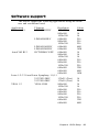
1
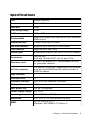
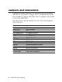
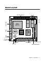
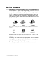
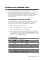
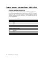
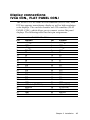
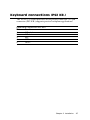
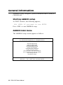
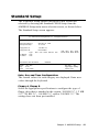
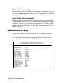
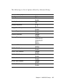
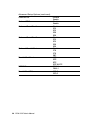
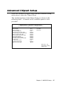
PCM-3335
All-in-one 386SX with Flat
Panel/CRT PC/104 Module
FCC STATEMENT
THIS DEVICE COMPLIES WITH PART 15 FCC RULES. OPERATION IS SUBJECT TO THE FOLLOWING TWO CONDITIONS:
(1) THIS DEVICE MAY NOT CAUSE HARMFUL INTERFERENCE. (2) THIS DEVICE MUST ACCEPT ANY INTERFERENCE
RECEIVED INCLUDING INTERFERENCE THAT MAY CAUSE
UNDESIRED OPERATION.
THIS EQUIPMENT HAS BEEN TESTED AND FOUND TO
COMPLY WITH THE LIMITS FOR A CLASS "A" DIGITAL
DEVICE, PURSUANT TO PART 15 OF THE FCC RULES.
THESE LIMITS ARE DESIGNED TO PROVIDE REASONABLE PROTECTION AGAINTST HARMFUL INTERFERENCE WHEN THE EQUIPMENT IS OPERATED IN A
COMMERCIAL ENVIRONMENT. THIS EQUIPMENT GENERATES, USES, AND CAN RADIATE RADIO FREQENCY
ENERGY AND , IF NOT INSTATLLED AND USED IN ACCORDANCE WITH THE INSTRUCTION MANUAL, MAY CAUSE
HARMFUL INTERFERENCE TO RADIO COMMUNICATIONS. OPERATION OF THIS EQUIPMENT IN A RESIDENTIAL AREA IS LIKELY TO CAUSE HARMFUL INTERFERENCE IN WHICH CASE THE USER WILL BE REQUIRED
TO CORRECT THE INTERFERENCE AT HIS OWN EXPENSE.
Copyright Notice
This document is copyrighted, 1995, 1996, by AAEON Technology
Inc. All rights are reserved. AAEON Technology Inc. reserves the
right to make improvements to the products described in this
manual at any time without notice.
No part of this manual may be reproduced, copied, translated or
transmitted in any form or by any means without the prior written
permission of AAEON Technology Inc. Information provided in
this manual is intended to be accurate and reliable. However,
AAEON Technology Inc. assumes no responsibility for its use, nor
for any infringements upon the rights of third parties which may
result from its use.
Acknowledgements
ALI is a trademark of Acer Laboratories, Inc.
AMI is a trademark of American Megatrends, Inc.
Cyrix is a trademark of Cyrix Corporation.
IBM, PC/AT, PS/2 and VGA are trademarks of International
Business Machines Corporation.
Intel and Pentium are trademarks of Intel Corporation.
Microsoft Windows® and MS-DOS are registered trademarks of
Microsoft Corp.
Part No. 2006335000 1st Edition
Printed in Taiwan October 1996
Packing list
Before you begin installing your card, please make sure that the
following materials have been shipped:
• 1 PCM-3335 CPU card
• 1 5-pin PC-AT keyboard adapter
• 1 Hard disk drive (IDE) interface cable (40 pin)
• 1 Floppy disk drive interface cable (34 pin)
• 1 Flat panel cable (44 pin)
• PC/104 module mounting supports
• 1 SVGA adapter (16 pin)
• 1 parallel port adapter (26-pin)
• 2 Serial port adapters (10-pin)
• 1 utility disk with SVGA utility programs and drivers
• 1 VGA BIOS disk which contains the standard BIOS files for
both CRT and LCD displays
If any of these items are missing or damaged, contact your distributor or sales representative immediately.
Contents
1 General Information ...................................... 1
Introduction ............................................................................ 2
Specifications .......................................................................... 3
2 Installation ................................................... 5
Jumpers and connectors ........................................................ 6
Board Layout .......................................................................... 7
Setting jumpers ...................................................................... 8
Safety precautions .................................................................. 9
IDE hard drive connections (HARD CON.) ...................... 10
Connecting the hard drive ...................................................... 10
Floppy drive connections (FLOPPY CON.) ...................... 12
Connecting the floppy drive ................................................... 12
Parallel port (PRINTER PORT) ........................................ 13
Installing the retaining bracket .............................................. 13
Power supply connections (CN4, CN6) ............................... 14
Power supply connector ......................................................... 14
Display connections (VGA CON., FLAT PANEL CON.) .. 15
Keyboard connections (PS2 KB.) ....................................... 17
Serial ports (COM1, COM2) .............................................. 18
Reset switch (RST SW.) ......................................................... 18
HDD LED (HD-LED) ............................................................ 19
Clear CMOS (CLEAR CMOS) ............................................. 19
3 AMIBIOS Setup ............................................ 21
General information ............................................................ 22
Starting AMIBIOS setup ........................................................ 22
AMIBIOS main menu ............................................................ 22
Standard Setup ..................................................................... 23
Advanced Setup .................................................................... 24
Advanced Chipset Setup ...................................................... 27
4 SVGA Setup ................................................. 31
Simultaneous display mode ................................................. 32
Sleep mode ............................................................................ 32
Software support .................................................................. 33
Driver installation ................................................................ 34
Windows setup ....................................................................... 35
AutoCAD R12 ....................................................................... 38
Lotus 1-2-3 and Lotus Symphony .......................................... 40
VESA ..................................................................................... 42
Word ....................................................................................... 43
WordPerfect............................................................................ 44
A Installing PC/104 Modules ........................... 47
Installing PC/104 modules................................................... 48
B LCD Display BIOS Configuration .................... 51
Configuring various LCD display ...................................... 52
CHAPTER
General
Information
1
This chapter provides background
information for the PCM-3335.
Sections include:
• Card specifications
• Board layout
Chapter 1 General Information
1
Introduction
The PCM-3335 comes equipped with an embedded microcontroller
ALI M6117 which is Intel 386SX-40 compatible. In addition, it
comes with two serial ports (RS-232), one bi-directional printer port
supporting SPP, ECP and EPP modes, an IDE HDD interface and a
floppy disk controller. With its industrial grade reliability, the PCM3335 can operate continuously at temperatures up to 140º F (60º C).
The PCM-3335 is specially designed as a compact all-in-one CPU
card which incorporates a PC/104 connector into its design, making
non-passive backplane SBC applications possible. The numerous
features provide an ideal price/performance solution for high-end
commercial and industrial applications where stability and reliability
are essential.
The PCM-3335 features an SVGA interface which supports CRT and
Flat Panel (TFT, STN, Mono and EL displays), with 512 KB on-board
display memory.
2
PCM-3335 User's Manual
Specifications
CPU
40MHz 80386SX
Bus Interface
PC/104 (ISA) bus
Data Bus
16-bit
Processing Ability
32-bit
RAM memory
2MB or 4MB
Shadow RAM
Support for system and video BIOS up to 256KB in
32KB blocks
Display Memory
512KB DRAM chip on board
IDE HDD interface
Supports up to two IDE (AT bus) HDDs
FDD interface
Supports up to two FDDs
Parallel port
Bi-directional parallel port (SPP/ECP/EPP modes)
Serial ports
Two RS-232
(both use 16C550 UART with 16-byte FIFO)
Real time clock
ALI M6117B internal RTC, lithium battery for up to
10 years data retention
PC/104 connector
104 pins for 16-bit bus. Supports pc/104 modules
such as Flash/RAM/ROM disk modules and/or a
PCMCIA module.
DMA channels
7
Interrupt levels
15
Keyboard interface
5-pin mini-DIN keyboard connector.
Bus speed
8 MHz
Max. power req.
+5V @ 1.5A (typical)
Power supply voltage
+5V ±10%
Operating temp.
32 to 140º F (0 to 60º C)
Board size
3.55" (L) x 3.775" (W) (90 mm x 96 mm)
MTBF
55,532 hours @ 25º C
(Standard: MIL-HDBK-217F Notice 1)
Chapter 1 General Information
3
4
PCM-3335 User's Manual
CHAPTER
Installation
2
This chapter explains set up procedures
for the PCM-3335 hardware, including
instructions on setting jumpers and
connecting peripherals, switches and
indicators. Be sure to read all safety
precautions before you begin the installation procedure.
Chapter 2 Installation
5
Jumpers and connectors
Connectors on the board link it to external devices such as hard
disk drives, a keyboard, or floppy drives. In addition, the board
has a number of jumpers that allow you to configure your system
to suit your application.
The table below lists the function of each of the board jumpers
and connectors:
Jumpers and connectors
Number
HARD CON.
FLOPPY CON.
FLAT PANEL CON.
PRINTER PORT
COM2
COM1
VGA CON.
CN2
CN1
PS2 KB
CN4, CN6
HD-LED
RST SW.
CLEARCMOS
6
PCM-3335 User's Manual
Function
HDD connector
FDD connector
LCD panel connector
Parallel port
COM2 (RS-232)
COM1 (RS-232)
VGA connector
PC/104 (64-pin)
PC/104 (40-pin)
External keyboard connector
Power connector
HDD LED connector
Reset switch connector
Clear CMOS connector
Board Layout
PC/104 Interface
PS2 KB.
PCM-3335
CN4
VGA CON.
CN6
ALI
DRAM
DRAM
M6117B
UMC
AMI
Flash
BIOS
UM8663BF
COM1
BAT.
COM2
CLEAR
CMOS
FLAT PANEL CON.
HD-LED
HARD CON.
RST SW.
FLOPPY CON.
PRINTER PORT
Chapter 2 Installation
7
Setting jumpers
You configure your card to match the needs of your application by
setting jumpers. A jumper is the simplest kind of electric switch. It
consists of two metal pins and a small metal clip (often protected
by a plastic cover) that slides over the pins to connect them. To
“close” a jumper you connect the pins with the clip. To “open” a
jumper you remove the clip. Sometimes a jumper will have three
pins, labeled 1, 2 and 3. In this case you would connect either pins
1 and 2 or 2 and 3.
1
Open
Closed
2
3
Closed 2-3
The jumper settings are schematically depicted in this manual as
follows:
1 2 3
Open
Closed
Closed 2-3
A pair of needle-nose pliers may be helpful when working with
jumpers.
If you have any doubts about the best hardware configuration for
your application, contact your local distributor or sales representative before you make any changes.
Generally, you simply need a standard cable to make most
connections.
8
PCM-3335 User's Manual
Safety precautions
Warning! Always completely disconnect the power cord
from your chassis whenever you are working on
it. Do not make connections while the power is
on because sensitive electronic components can
be damaged by the sudden rush of power. Only
experienced electronics personnel should open
the PC chassis.
Caution! Always ground yourself to remove any static
charge before touching the CPU card. Modern
electronic devices are very sensitive to static
electric charges. Use a grounding wrist strap at
all times. Place all electronic components on a
static-dissipative surface or in a static-shielded
bag when they are not in the chassis.
Chapter 2 Installation
9
IDE hard drive connections
(HARD CON.)
You can attach two Enhanced Integrated Device Electronics hard
disk drives to the PCM-3335's internal controller. The card comes
with a 40-pin flat cable.
Connecting the hard drive
Wire number 1 on the cable is red or blue, and the other wires are
gray.
1. Connect one end of the cable to the IDE connector. Make sure
that the red (or blue) wire corresponds to pin 1 on the connector, which is labeled on the board (on the right side).
2. Plug the other end of the cable to the Enhanced IDE hard
drive, with pin 1 on the cable corresponding to pin 1 on the
hard drive. (See your hard drive's documentation for the
location of the connector.)
Unlike floppy drives, you can make the connections with any of
the connectors on the cable. If you install two drives, you will
need to set one as the master and one as the slave. You do this
using jumpers on the drives. If you install just one drive, set it as
the master.
10
PCM-3335 User's Manual
Pin assignments
The following table lists the pin numbers and their respective
signals:
IDE Connector (HARD CON.)
Pin
1
3
5
7
9
11
13
15
17
19
21
23
25
27
29
31
33
35
37
39
41
43
Signal
Reset
D7
D6
D5
D4
D3
D2
D1
D0
GND
N.C,
IOW
IOR
IORDY
N.C.
IRQ
A1
A0
CS0
-ACT
VCC
GND
Pin
2
4
6
8
10
12
14
16
18
20
22
24
26
28
30
32
34
36
38
40
42
44
Signal
GND
D8
D9
D10
D11
D12
D13
D14
D15
N.C.
GND
GND
GND
BALE
GND
-I/O CS16
N.C.
A2
CS1
GND
VCC
NC
Chapter 2 Installation
11
Floppy drive connections (FLOPPY CON.)
You can attach up to two floppy disks to the PCM-3335's on-board
controller. You can use any combination of 5¼" (360 KB and 1.2
MB) and/or 3½" (720 KB, 1.44 MB, and 2.88 MB) drives.
The PCM-3335 CPU card comes with a 34-pin daisy-chain drive
connector cable. On one end of the cable is a 34-pin flat-cable
connector. There are two sets of floppy disk drive connectors,
one in the middle, and one on the other end. Each set consists of
a 34-pin flat-cable connector (usually used for 3.5" drives) and a
printed-circuit board connector (usually used for 5.25" drives).
Connecting the floppy drive
1. Plug the 34-pin flat-cable connector into the floppy disk
connector.
2. Attach the appropriate connector on the other end of the cable
to the floppy drive(s). You can use only one connector in the
set. The set on the end (after the twist in the cable) connects
to the A: floppy. The set in the middle connects to the B:
floppy.
Pin assignments
The following table lists the pin assignments for the floppy disk
connector:
FLOPPY DISK Connector (FLOPPY CON.)
Pin
Signal
1~33 (odd) GND
4, 6
Unused
10
Motor enable A
14
Driver select A
18
Direction
22
Write data
26
Track 0
30
Read data
34
Disk change
12
PCM-3335 User's Manual
Pin
2
8
12
16
20
24
28
32
Signal
High density
Index
Driver select B
Motor enable B
Step pulse
Write enable
Write protect
Select head
Parallel port (PRINTER PORT)
Normally, the parallel port is used to connect the card to a printer.
The PCM-3335 includes an on-board parallel port, accessed
through PRINTER PORT, and a 26-pin flat-cable connector. The
CPU card comes with an adapter cable, which lets you use a
traditional DB-25 connector. The cable has a 26-pin connector on
one end and a DB-25 connector on the other, mounted on a
retaining bracket.
Installing the retaining bracket
The retaining bracket installs at an empty slot in your system's
chassis. It provides an external port that allows your parallel
peripheral to access to the card's parallel port connector.
1. Find an empty slot in your chassis.
2. Unscrew the plate that covers the end of the slot.
3. Screw in the bracket in place of the plate.
4. Next, attach the flat-cable connector to PRINTER PORT. Wire
1 of the cable is red or blue, and the other wires are gray. Make
sure that Wire 1 connects to Pin 1 of PRINTER PORT. Pin 1 is
on the right side of PRINTER PORT.
Pin assignments
PRINTER Connector (PRINTER PORT)
Pin
1
3
5
7
9
11
13
15
17
Signal
Strobe
Data 1
Data 3
Data 5
Data 9
Busy
+ Select
- Error
- Select input
Pin
2
4
6
8
10
12
14
16
18~25
Signal
Data 0
Data 2
Data 4
Data 6
-Acknowledge
Paper empty
- Auto feed
- Init printer
GND
Chapter 2 Installation
13
Power supply connections (CN4, CN6)
Power supply connector
In single board computer (non-passive backplane) applications,
you will need to connect power directly to the PCM-3335 board
using CN4 and CN6. This connector is fully compatible with the
standard PC power supply connectors. See the following table for
its pin assignments:
Power connector (CN6)
Pin
1
2
3
4
Function
+12 V
GND
GND
+5 V
Power connector (CN4)
Pin
1
2
3
14
Function
-12 V
GND
-5 V
PCM-3335 User's Manual
Display connections
(VGA CON., FLAT PANEL CON.)
The PCM-3335 CPU card's SVGA connector (VGA CON.) with
PCI bus supports monochrome display as well as high resolution
color displays. The card also features an LCD connector (FLAT
PANEL CON.), which allows you to connect various flat panel
displays. The following table lists their pin assignments:
LCD connector (FLAT PANEL CON.)
Pin
1
3
5
7
9
11
13
15
17
19
21
23
25
27
29
31
33
35
37
39
41
43
Function
+12 VDC
GND
+5 VDC
EN LCD
P0
P2
P4
P6
P8
P10
P12
P14
P16
P18
P20
P22
GND
LCD clock (SHFCLK)
ACDCLK
GND
GND
+5 V
Pin
2
4
6
8
10
12
14
16
18
20
22
24
26
28
30
32
34
36
38
40
42
44
Function
+12 VDC
GND
+5 VDC
GND
P1
P3
P5
P7
P9
P11
P13
P15
P17
P19
P21
P23
GND
FLM (V SYS)
LP (H SYS)
-Blank
ASFCLK
+5 V
Chapter 2 Installation
15
SVGA connector (VGA CON.)
Pin
1
2
3
4
5
6
7
8
16
Function
RED
NC
GREEN
SIGNAL GND
BLUE
NC
NC
NC
PCM-3335 User's Manual
Pin
9
10
11
12
13
14
15
16
Function
SIGNAL GND
H-SYNC
CHASSIS GND
V-SYNC
CHASSIS GND
NC
CHASSIS GND
NC
Keyboard connections (PS2 KB.)
The PCM-3335 board provides one keyboard connector. A 5-pin
connector (PS2 KB.) supports passive backplane applications.
Keyboard connector (PS2 KB.)
Pin
1
2
3
4
5
Function
K.B. clock
K.B. data
N.C.
GND
+5 VDC
Chapter 2 Installation
17
Serial ports (COM1, COM2)
The PCM-3335 offers two serial ports (RS-232). These ports let
you connect to serial devices (a mouse, printers, etc.), or a communication network.
Reset switch (COM1, COM2)
Pin
1
2
3
4
5
6
7
8
9
10
Signal
DCD
RxD
TxD
DTR
GND
DSR
RTS
CTS
RI
N/C
Reset switch (RST SW.)
You can connect an external switch to easily reset your computer.
This switch restarts your computer as if you had turned off the
power then turned it back on. The following table shows the pin
assignments for the RST SW.
Reset switch (RST SW.)
Pin
1
2
18
Function
Reset
GND
PCM-3335 User's Manual
HDD LED (HD-LED)
You can connect a LED to indicate that an IDE device is in use.
The pin assignments for this jumper are as follows.
HDD LED pin assignments (HD-LED)
Pin
1
2
Function
-R/W IDE
Pull high
Clear CMOS (CLEAR CMOS)
You can connect an external switch to clear CMOS. This switch
closes CLEAR CMOS and turns on the power, at which time the
CMOS setup can be cleared.
Clear CMOS (CLEAR CMOS)
Protect (default)
1
2
3
Clear CMOS
1
2
3
Chapter 2 Installation
19
20
PCM-3335 User's Manual
CHAPTER
AMIBIOS Setup
3
This chapter describes how to set BIOS
configuration data.
General information
AMIBIOS Setup configures system information that is stored in
CMOS RAM.
Starting AMIBIOS setup
As POST executes, the following appears;
Hit <DEL> if you want to run SETUP
Press <DEL> to run AMIBIOS setup.
AMIBIOS main menu
The AMIBIOS setup screen appears as follows:
AMIBIOS SETUP — BIOS SETUP UTILITIES
(C) 1995 American Megatrends, Inc. All Rights Reserved
Standard CMOS Setup
Advanced CMOS Setup
Advanced Chipset Setup
Power Management Setup
Change User Password
Change Supervisor Password
Change Language Setting
Auto-configuration with Optimal Settings
Auto Configuration with Fail Safe Settings
Save Settings and Exit
Exit Without Saving
Standard CMOS setup for changing time, date, hard disk type, etc.
ESC: Exit
:Sel F2/F3: Color F10: Save and Exit
22 PCM-3335 User's Manual
Standard Setup
The AMIBIOS Setup options described in this section are
selected by choosing the Standard CMOS Setup from the
AMIBIOS Setup main menu selection screen, as shown below.
The Standard Setup screen appears:
AMIBIOS SETUP — STANDARD CMOS SETUP
(C) 1995 American Megatrends, Inc. All Rights Reserved
Date (mm/dd/yyyy):
Time (hh/mm/ss):
Wed Aug 21, 1996
12: 19: 46
Floppy Drive A:
Floppy Drive B:
1.44 MB 3½"
Not Installed
Pri Master:
Pri Slave
Type
Auto
Auto
Size Cyln Head WPcom Sec
Boot Sector Virus Protection
Month:
Day:
Year:
LBA BLK PIO 32-bit
Mode Mode Mode Mode
Disabled
Jan - Dec
01-31
1901 -2099
Esc: Exit
:Sel
PgUp/PgDn: Modify
F2/F3: Color
Date, Day and Time Configuration
The current values for each category are displayed. Enter new
values through the keyboard.
Floppy A, Floppy B
Select the appropriate specifications to configure the type of
floppy drive that is attached to the system: 360 KB 5¼", 1.2 MB
5¼", 720 KB 3½", 1.44 MB 3½", and/or 2.88 MB 3½". The
settings have not been pre-installed.
Chapter 3 AMI BIOS setup
23
Master Disk, Slave Disk
Select the appropriate values to configure the hard disk type you
are using for the master and the slave. The settings have not been
pre-installed. Available types are 1~46, User and Auto.
Boot Sector Virus Protection
Enabling this option allows the system to issue a warning when
any program (or virus) issues a disk format command or attempts
to write to the boot sector of the hard disk drive. Further confirmation is required before accessing this particular section of the
hard disk drive.
Advanced Setup
Select the Advanced CMOS Setup from the AMIBIOS Setup
main menu to enter Advanced setup.
The Advanced Setup options described in this section are the
standard options as shown on the following screen.
AMIBIOS SETUP — ADVANCED CMOS SETUP
(C) 1995 American Megatrends, Inc. All Rights Reserved
Quick Boot
BootUp Num-Lock
BootUp Sequence
Floppy Drive Swap
Mouse Support
System Keyboard
Primary Display
Password Check
C000, 32K Shadow
C800, 32K Shadow
D000, 32K Shadow
D800, 32K Shadow
E000, 32K Shadow
E800, 32K Shadow
Onboard IDE
Onboard FDC
Onboard Serial Port 1
Onboard Serial Port 2
Onboard Parallel Port
Parallel Port Mode
ECP DMA
Parallel Port IRQ
24 PCM-3335 User's Manual
Enabled
On
C:, A:
Disabled
Enabled
Present
EGA/VGA
Setup
Enable
Disabled
Disabled
Disabled
Disabled
Disabled
Enabled
Enabled
3F8
2F8
378
SPP
DMA 3
IRQ 7
The following is a list of options offered by Advanced Setup.
Advanced Setup Options
Function
Quick Boot
BootUp Num-Lock
BootUp Sequence
Floppy Drive Swap
Mouse Support
System Keyboard
Primary Display
Password Check
CO0O, 32K, Shadow
C8OO, 32K, Shadow
D0OO, 32K, Shadow
D8OO, 32K, Shadow
E0OO, 32K, Shadow
E8OO, 32K, Shadow
Options
Disable
Enable
On
Off
C:, A:
A:, C:
Disable
Enable
Disable
Enable
Disable
Enable
VGA/EGA
CGA 40 x 25
CGA 80 x 25
Mono
Absent
Setup
Always
Disable
Enable
Disable
Enable
Disable
Enable
Disable
Enable
Disable
Enable
Disable
Enable
Chapter 3 AMI BIOS setup
25
Advanced Setup Options (continued)
Onboard IDE
Onboard FDC
Onboard Serial Port 1
Onboard Serial Port 2
Onboard Parallel Port
Parallel Port Mode
ECP DMA
Parallel Port IRQ
26 PCM-3335 User's Manual
Disable
Enable
Disable
Enable
Disable
3F8
2F8
3E8
2E8
Disable
3F8
2F8
3E8
2E8
Disable
378
278
3BC
SPP
EPP
ECP
EPP & ECP
DMA 3
DMA 1
IRQ 7
IRQ 5
Advanced Chipset Setup
Select the Advanced Chipset Setup from the AMIBIOS Setup
main menu to enter the Chipset Setup.
The standard options of the Chipset Setup are shown in the
following table. A detailed list of available options is also
provided.
AMIBIOS SETUP — ADVANCED CHIPSET SETUP
(C) 1995 American Megatrends, Inc. All Rights Reserved
AT Bus Clock
Slow Refresh
Memory Remap
RAS Precharge time
RAS Active Time Insert Wait
CAS Precharge Time Insert Wait
Memory Write Insert Wait
Memory Miss Read Insert Wait
ISA I/O High Speed
ISA Memory High Speed
ISA Write cycle end Insert Write
I/O Recovery
I/O Recovery Period
On-Chip I/O Recovery
16Bit ISA Insert Wait
14.318/2
15 us
Disable
2.5T
Disable
Disable
Disable
Disable
Disable
Disable
Disable
Disable
0 us
Disable
Disable
Available Options:
14.318/2
PCLK2/10
ESC: Exit :Sel
PgUp/PgDn: Modify
F2/F3: Color
Chapter 3 AMI BIOS setup
27
Chipset Setup Options
Function
At Bus Clock
Slow Refresh
Memory Remap
RAS Precharge Time
RAS Active Time Insert Wait
CAS Precharge Time Insert Wait
Memory Write Insert Wait
Memory Miss Read Insert Wait
ISA I/O High Speed
ISA Memory High Speed
ISA Write cycle end Insert Wait
I/O Recovery
I/O Recovery Period
On-Chip I/O Recovery
16-bit ISA Insert Wait
28 PCM-3335 User's Manual
Options
14.318/2
PCLK2/10
15us
6Ous
120us
Disable
Enable
1.5T
2.5T
3.5T
Disable
Enable
Disable
Enable
Disable
Enable
Disable
Enable
Disable
Enable
Disable
Enable
Disable
Enable
Disable
Enable
Disable
Enable
Disable
Enable
Disable
Enable
Change User Password
1) Select this option from the main menu
2) Enter the Password and Press <Enter>
3) Retype the Password and Press <Enter>
If you forget the user's password, please contact your distributor
for another password which you can use to enter the BIOS setup
and change your own password.
Auto Configuration with Optimal Settings
You can load the optimal default settings for the AMIBIOS setup
options by selecting it from the main menu. The optimal default
settings are best case values that should optimize system performance. If CMOS RAM is corrupted, the optimal settings are
loaded automatically.
Auto Configuration with Fail Safe Setting
You can load the Fail Safe setting for the AMIBIOS setup
options by selecting it from the main menu. The Fail Safe setting
provides the most stable settings, though they may not provide
optimal performance. Use this option as a diagnostic aid if the
system is behaving erratically.
Chapter 3 AMI BIOS setup
29
30 PCM-3335 User's Manual
CHAPTER
SVGA Setup
4
The PCM-3335 features an on-board flat
panel/VGA interface. This chapter
provides instructions for installing and
operating the software drivers on the
included display driver diskette.
Simultaneous display mode
The 65545 VGA BIOS supports monochrome LCD, EL, color TFT
and STN LCD flat panel displays. It also supports interlaced and
non-interlaced analog monitors (VGA color and VGA monochrome) in high-resolution modes while maintaining complete
IBM VGA compatibility. Digital monitors (i.e. MDA, CGA, and
EGA) are NOT supported. Multiple frequency (multisync)
monitors are supported as analog monitors.
Both CRT and panel displays can be used simultaneously. The
PCM-3335 can be set in one of three configurations: on a CRT, on
a flat panel display, or on both simultaneously. The system is
initially set to simultaneous display mode. In the utility diskette,
there are three COM files which can be used to select the display.
Simply type the filename at the DOS prompt:
CT.COM Enables CRT display only
FP.COM Enables panel display only
SM.COM Enables both displays at the same time.
Sleep mode
The display driver diskette contains two files that support sleep
mode. Simply type the filename at the DOS prompt:
ON.COM switches to normal display mode.
OFF.COM switches to sleep mode.
32
PCM-3335 User's Manual
Software support
The drivers support the following applications using the filenames and resolutions listed:
Application
Windows 3.1
Filename
LINEAR4.DRV
LINEAR8.DRV
AutoCAD R12
LINEAR16.DRV
LINEAR24.DRV
RCTURBOC.EXP
Resolution
640x480
800x600
1024x768
640x480
800x600
1024x768
640x480
640x480
640x480
800x600
1024x768
640x480
800x600
1024x768
640x480
640x480
640x480
Lotus 1-2-3 2.0 and Lotus Symphony 1.0,1.1
V132X25.DRV
132x25 (Text)
V132X50.DRV
132x50 (Text)
VESA 1.2
VESA.COM
800x600
1024x768
640x400
640x480
800x600
1024x768
640x480
640x480
Colors
16
16
16
256
256
256
64K
16M
16
16
16
256
256
256
32K
64K
16M
16
16
16
16
256
256
256
256
32K
64K
Chapter 4 SVGA Setup
33
Word 5.0
Word 5.5
WordPerfect 5.0
WordPerfect 5.1
VGA600.VID
VGA768.VID
VGA55600.VID
VGA55768.VID
CHIPS600.WPD
CHIPS768.WPD
VGA600.VRS
VGA768.VRS
800x600
1024x768
800x600
1024x768
800x600
1024x768
800x600
1024x768
16
16
16
16
16
16
16
16
Driver installation
Necessary prerequisites
The instructions in this manual assume that you understand
elementary concepts of MS-DOS and the IBM Personal Computer. Before you attempt to install any driver or utility you should:
know how to copy files from a floppy disk to a directory on the
hard disk, understand the MS-DOS directory structure, and know
how to format a floppy disk. If you are uncertain about any of
these concepts, please refer to the DOS or Windows user reference guides for more information before you proceed with the
installation.
Before you begin
Before you begin installing software drivers, you should make a
backup copy of the display driver diskette and store the original
in a safe place. The display driver diskette contains drivers for
several versions of certain applications. You must install the
correct version in order for the driver to work properly so make
sure you know which version of the application you have.
34
PCM-3335 User's Manual
Windows setup
These drivers are designed to work with Microsoft Windows 3.1.
You may install these drivers through Windows or in DOS.
Step 1: Install Windows as you normally would for a VGA
display. Run Windows to make sure that it is working correctly.
Step 2: Place the display driver diskette in drive A. In Windows
Program Manager, choose File from the Options Menu. Then
from the pull-down menu, choose Run . . . . At the command line
prompt, type A:\WINSETUP. Press the <ENTER> key or click
OK to begin the installation. At this point the setup program
locates the directory where Windows is installed. For proper
operation, the drivers must be installed in the Windows subdirectory. Press <ENTER> to complete the installation. Once completed, the Display Driver Control Panel appears on the screen. This
Control Panel allows you to select and load the installed drivers.
Another method of installing these drivers is through the File
Manager. Click on Drive A:. Then double-click on
WINSETUP.EXE to begin installation.
Changing Display Drivers in Windows
To change display drivers in Windows, select the Windows Setup
icon from the Main window. You will be shown the current setup
configuration. Select Change System Settings from the Option
menu. Click on the arrow at the end of the Display line. You will
be shown a list of display drivers. Click on the driver you want.
Then click on the OK button. Follow the directions to complete
the setup.
Changing Color Schemes
After you change display drivers, you may notice that the color
scheme used by Windows looks strange. This is because different
drivers have different default colors. To change the color scheme,
select the Control Panel from the Main window. Select the Color
icon. You will be shown the current color scheme. Choose a new
color scheme and click the OK button.
Chapter 4 SVGA Setup
35
DOS Setup
Step 1: Install Windows as you normally would for a VGA
display. Run Windows to make sure that it is working correctly.
Then exit Windows.
Step 2: Place the display driver diskette in drive A. Type A:
<ENTER> to make this the default drive. Type SETUP <ENTER> to run the driver SETUP program. Press any key to get to
the applications list. Using the arrow keys, select Windows
Version 3.1 and press the <ENTER> key. Press the <ENTER>
key to select All Resolutions, and then press <END> to begin the
installation. At this point you will be asked for the path to your
Windows System directory (default C:\WINDOWS). When the
installation is complete, press any key to continue. Press <ESC>
followed by Y to exit to DOS.
Step 3: Change to the directory where you installed Windows
(usually C:\WINDOWS).
Step 4: Type SETUP <ENTER> to run the Windows Setup
program. It will show the current Windows configuration. Use
the up arrow key to move to the Display line and press <ENTER>. A list of display drivers will be shown. Use the arrow
keys to select one of the drivers starting with an asterisk (*) and
press <ENTER>.
Step 5: Follow the directions on the screen to complete the setup.
In most cases, you may press <ENTER> to accept the suggested
option. When Setup is done, it will return to DOS. Type WIN
<ENTER> to start Windows with the new display driver.
Changing Display Drivers in DOS
To change display drivers from DOS, change to the Windows
directory and run Setup, repeating steps 4 and 5 from the previous page. Besides the special display drivers marked by an
asterisk (*), you should be able to use the following standard
drivers:
36
VGA
640x480, 16 colors
Super VGA
800x600, 16 colors
PCM-3335 User's Manual
Panning Drivers
Special panning drivers are provided to allow high-resolution
modes to be displayed on a flat panel or CRT. These drivers will
show a section of a larger screen and will automatically pan, or
scroll, the screen horizontally and vertically when the mouse
reaches the edge of the display.
Linear Acceleration Drivers
A special high-performance linear acceleration driver is provided
for 256-color modes. This driver may require special hardware
and may not be supported on all systems. It is only available for
Windows3.1.
Chapter 4 SVGA Setup
37
AutoCAD R12
These drivers are designed to work with Autodesk AutoCAD
R12. They conform to the Autodesk Device Interface (ADI) for
Rendering drivers and Display drivers. These display list drivers
accelerate redraw, pan, and zoom functions.
Driver installation
Step 1: Place the display driver diskette in drive A. Type A:
<ENTER> to make this the default drive. Type SETUP <ENTER> to run the SETUP program. Press any key to get to the
applications list. Using the arrow keys, select AutoCAD Release
12 and press <ENTER>. This will display a list of supported
driver resolutions. Using the arrow keys and the <ENTER> key,
select the resolutions that are appropriate for your monitor. When
all of the desired resolutions have been selected, press <END> to
begin the installation. At this point you will be asked for a drive
and directory to copy the driver files. Enter the drive and directory that contains the installed AutoCAD R12. If the destination
directory does not exist you will be asked for confirmation. When
the installation is complete, press any key to continue. Press
<ESC> followed by Y to exit to DOS.
Step 2: Go to the AutoCAD directory where the new drivers were
installed and run the driver installation program by typing
ACAD12 -r <ENTER>. This program will configure your
AutoCAD R12 to use the new display drivers. Select TurboDLD
Classic.
Configuring TurboDLD
Select Configure Video Display. In Display Device Configuration choose Select Graphics Board/Resolution. Then choose
Select Display Graphics Board. After choosing a graphics board,
go to Select Display Resolution. After selecting the display
resolution, save the new configuration, and return to the main
menu.
38
PCM-3335 User's Manual
Basic Configuration Menu
This menu allows you to modify:
Number of AutoCAD Command Lines
Font Size
6x8/8x8/8x14/8x16/12x20/12x24
Dual Screen
Enable/Disable
User Interface Configuration
Double Click Interval Time
BP Button
BP Highlight
Patt Line/Xor Rect/Both
BP Refresh
Enable/Disable
BP Cache
Enable/Disable
Expert Configuration Menu
This menu allows you to modify:
Display List
Enable/Disable
Drawing Cache
Enable/Disable
Use Acad 31 bit space?
Yes/No
Internal Command Echo
Enable/Disable
BP Zoom Mode
Freeze/Float
Regen Mode
Incremental/Fast
If your previously installed driver is not TurboDLD, you will
have to reconfigure the RENDER command the first time you use
it.
Chapter 4 SVGA Setup
39
Lotus 1-2-3 and Lotus Symphony
These drivers are designed to work with Lotus 1-2-3 versions 2.0,
2.01 and 2.2, and with Lotus Symphony versions 1.0 and 1.1.
Driver installation
Step 1: Place the display driver diskette into drive A. Make A the
default drive by typing A: <ENTER>. Run the SETUP program
by typing SETUP <ENTER>. Press any key to display a list of
supported applications. Use the arrow keys to select Lotus/
Symphony, and press <ENTER>. A list of supported screen
resolutions will be displayed. Use the arrow keys to select the
desired screen resolution and press <ENTER>. (Make sure your
monitor is able to display the resolution desired) Press <END> to
begin the driver installation process. A default drive and directory path will be displayed. Use the backspace key to erase this
default and type in the 123 directory. At this point you may be
asked to create the target directory if it does not already exist.
After the files have been installed, press any key to return to the
list of supported applications. Press <ESC> followed by Y to exit
to DOS. Copy all the files that were just created in the temporary
directory onto a formatted floppy diskette.
Step 2: Go to your 123 directory, and start the installation
program. Type the following commands:
C: <ENTER>
INSTALL <ENTER>
Step 3: The Lotus installation program will load and present the
installation menu. From this menu, select Advanced Options.
From the Advanced Options menu, select Add New Drivers To
Library. From the Add New Drivers Menu, select Modify
Current Driver Set. From the Modify Driver Set Menu, select
Text Display. From the Text Display menu, select one of drivers.
Step 4: After the selection of the appropriate VGA display driver,
you will need to exit this menu and return to the Main Lotus
Installation Menu. Do this by selecting Return To Menu.
Step 5: At the Lotus Installation Menu, select Save Changes.
40
PCM-3335 User's Manual
Step 6: At this point the Installation Menu will prompt you for
the name of your new Lotus configuration file. The Lotus system
will prompt you with the default value — 123.SET, but you may
want to use a filename that indicates the resolution of its driver.
For example, if you installed the 132 column by 25 line driver,
you could name this driver 132X25.SET, or if you installed the
80 by 50 driver, you may want to call the file 80X50.SET.
Step 7: The installation of your Lotus 1-2-3 driver is now
complete. You will need to exit the Lotus installation program at
this point. At the main Lotus Installation Menu, select Exit.
NOTE: If your driver set is not 123.SET, you have to type the
filename of your driver set in the command line when you start
Lotus 1-2-3. For example, if you named your driver set
132X25.SET, type the following to start Lotus 1-2-3:
123 132X25.SET <ENTER>
Chapter 4 SVGA Setup
41
VESA
The Video Electronics Standards Association (VESA) has created
a standard for a Super VGA BIOS Extension (VBE). This defines
a standard software interface to allow application programs to set
and control extended video modes, such as 800x600 graphics, on
video adapters from different manufacturers.
The VESA driver adds this Super VGA BIOS Extension to the
VGA BIOS. Any application program which supports the VESA
standard driver interface can be used with this driver. This VESA
driver conforms to the VESA Super VGA Standard #VS891001.
Driver installation
Step 1: Place the display driver diskette into drive A. Make A the
default drive by typing A: <ENTER>. Run the SETUP program
by typing SETUP <ENTER>. Press any key to display a list of
supported applications. Use the arrow keys to select VESA
Driver Version 1.2 and press <ENTER>. Press the <ENTER>
key to select All Resolutions, and press <END> to begin the
installation. A default drive and directory path will be displayed.
Use the backspace key to erase this and type in a directory that is
in the directory path (such as C:\BIN or C:\UTILS). After the
files have been installed, press any key to return to the list of
supported applications. Press <ESC> followed by Y to exit to
DOS.
Step 2: To install the VESA driver, type either VESA <ENTER>
or VESA + <ENTER> at the DOS prompt. The optional +
command line parameter enables all of the available modes.
Make sure that your monitor is capable of displaying these high
resolution modes before enabling them.
NOTE: If the video BIOS already supports VBE extended video
modes, DO NOT use this driver. Run the VTEST.EXE program
to see if the video BIOS supports the VBE modes.
42
PCM-3335 User's Manual
Word
These drivers are designed to work with Microsoft Word 5.0 and
5.5.
Driver installation
If you have already installed Word on your computer, go to Step
2 to install the new video driver.
Step 1: Install Word as normal.
Step 2: After you complete the Word installation, place the
display driver diskette into drive A. Make A the default drive by
typing A: <ENTER>. Run the SETUP program by typing
SETUP <ENTER>. Press any key to display a list of supported
applications. Use the arrow keys to select Word and press
<ENTER>. Use the arrow keys to select the desired screen
resolution and press <ENTER> (make sure your monitor is able
to display the resolution desired). Press <END> to begin the
driver installation process. A default drive and directory path will
be displayed. Use the backspace key to erase this and type in
your Word directory. After the files have been installed, press
any key to return to the list of supported applications. Press
<ESC> followed by Y to exit to DOS.
Step 3: Copy the driver file for the desired resolution that was
just installed to SCREEN.VID.
Chapter 4 SVGA Setup
43
WordPerfect
These drivers are designed to work with WordPerfect 5.0 or 5.1.
They support 132-column display in editing mode, and highresolution graphics display in PreView mode.
Driver installation
Step 1: Place the display driver diskette into drive A. Make A the
default drive by typing A: <ENTER>. Run the SETUP program
by typing SETUP <ENTER>. Press any key to display a list of
supported applications. Use the arrow keys to select WordPerfect
and press <ENTER>. A list of supported screen resolutions will
be displayed. Use the arrow keys to select the desired screen
resolution and press <ENTER> (make sure your monitor is able
to display the resolution desired). Press <END> to begin the
driver installation process. A default drive and directory path will
be displayed. Use the backspace key to erase this default and type
in the WordPerfect directory. At this point you may be asked to
create the target directory if it does not already exist. After the
files have been installed, press any key to return to the list of
supported applications. Press <ESC> followed by Y to exit to
DOS.
Step 2: Start WordPerfect, and press <SHIFT>+<F1> to enter the
setup menu. Select D for Display and G for Graphics Screen
Type, and then choose the desired Chips VGA resolution.
44
PCM-3335 User's Manual
Configuring WordPerfect 5.0 for 132 columns
Follow these instructions to configure WordPerfect 5.0 for 132
column text mode:
Step 1: To use the SETCOL program to set 132 columns and 25
rows, type the following command:
SETCOL 132, 25 <ENTER>
Step 2: Start WordPerfect. The program will detect the number
of rows and columns automatically. If for some reason WordPerfect is unable to adapt to 132 columns by 25 rows, start WordPerfect with the following command:
WP /SS=25,132 <ENTER>
Configuring WordPerfect 5.1 for 132 columns
Start WordPerfect and press <SHIFT>+<F1> to enter the setup
menu. Select D for Display and T for Text Screen Type and then
select Chips 132 Column Text.
Chapter 4 SVGA Setup
45
46
PCM-3335 User's Manual
APPENDIX
Installing PC/104
Modules
A
This appendix gives instructions for
installing PC/104 modules.
Installing PC/104 modules
The PCM-3335's PC/104 connectors give you the flexibility to
attach PC/104 expansion modules. These modules perform the
functions of traditional plug-in expansion cards, but save space
and valuable slots. Modules include:
• PCM-3810
Solid State Disk Module
• PCM-3820
High Density Flash Disk Module
• PCM-3110
PCMCIA Module
• PCM-3111
Secondary PCMCIA Module
• PCM-3610
Isolated RS-232 and RS-422/485 Module
• PCM-3660
Ethernet Module
• PCM-3718
30 KHz A/D Module
• PCM-3724
48-channel DIO Module
• PCM-3910
Breadboard Module
Installing these modules on the PCM-3335 is a quick and simple
operation. The following steps indicate how to mount the PC/104
modules:
Step1
Remove the PCM-3335 from your system paying
particular attention to the safety instructions already
mentioned above.
Step2
Make any jumper or link changes required to the CPU
card now. Once the PC/104 module is mounted, you
may have difficulty in accessing these.
Step3
Normal PC/104 modules have "male" connectors and
mount directly onto the main card. Please refer to the
PC/104 module mounting diagram on the following
page. After this is in place, you have the correct
mounting connector to accept your PC/104 module.
48 PCM-3335 User's Manual
Step4
Mount the PC/104 module onto the CPU card. Do this
by pressing the module firmly but carefully onto the
mounting connectors.
Step5
Secure the PC/104 module onto the CPU card using
the four mounting spacers and screws.
PC/104
Mounting Support
Male
PCM-3335
CPU Card
Female
Male
PC/104 Module
PC/104 Module Mounting Diagram
Appendix A Installing PC/104 Modules
49
3.500
3.250
3.775
3.575
3.575
0.200
0.200
0
0.200
0
3.350
3.550
PC/104 module dimensions (inches ±5 %)
50 PCM-3335 User's Manual
APPENDIX
LCD Display BIOS
Configuration
B
This appendix gives instructions for
configuring various LCD displays.
Configuring various LCD display
Follow the instructions below to integrate an LCD VGA BIOS into
the PCM-3335 system BIOS.
1. Combine the VGA BIOS with the system BIOS following the
instructions at the DOS prompt.
DEBUG
-N
-L
-N
-L
-R
CX 2000
:0
-R
BX 0000
:2
-N
4000:0
CX
; DOS utility program
<ENTER>
<ENTER>
<ENTER>; Read STN.DAT in BIOS files
for example
<ENTER>
<ENTER>
BX
<ENTER>
<ENTER>
-W
-Q
4000:0
SBC-355.ROM
4000:0
<VGABIOS.DAT>
<Newfile.ROM>
<ENTER>
<ENTER>; Assign new file name to
new SBC-355V BIOS
<ENTER>; Write the BIOS back to disk
<ENTER>
2. Use the utility program AMIFLASH.COM to write the system
BIOS file you just created to the BIOS chip on board.
AMIFLASH <Newfile.ROM>
52 PCM-3335 User's Manual