1
PC24EK1
PC30EK1
PC36EK1
PC42EK1
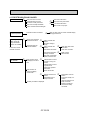
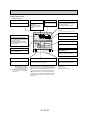
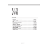
CONTENTS
1. TECHNICAL CHANGE ··················································································OC192- 2
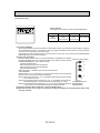
2. FEATURES ····································································································OC192- 3
3. PART NAMES AND FUNCTIONS ··································································OC192- 6
4. SPECIFICATIONS ··························································································OC192- 8
5. DATA ··············································································································OC192- 9
6. OUTLINES AND DIMENSIONS ····································································OC192-16
7. REFRIGERANT SYSTEM DIAGRAM ····························································OC192-18
8. WIRING DIAGRAM ························································································OC192-19
9. OPERATION FLOW-CHART ··········································································OC192-20
10. MICROPROCESSOR CONTROL ··································································OC192-23
11. TROUBLESHOOTING ····················································································OC192-34
12. SYSTEM CONTROL ······················································································OC192-40
13. DISASSEMBLY PROCEDURE ······································································OC192-45
14. PARTS LIST ····································································································OC192-50
15. OPTIONAL PARTS ························································································OC192-57
OC192-1
1
TECHNICAL CHANGE
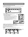
Differences with OC001 which is a basic service manual.
EK
EK1
4-3/4 o 2-3/4 o 5/8
5-1/8 o 4-3/4 o 3/4 No.9
Switch for temperature unit
Canceled
Change points
Appearances
Remote
controller
Indoor controller
Optional parts
Dip switch
SW17
No.0
Switch for louvers
Canceled
SW18
—
Addition of "Mode selector"
SW1
No.10
OFF
ON
Dip switch
SW5
No.3
—
Addition of "Not yet used"
No.4
—
Addition of "LOSSNAY interlocked or not"
SW6
—
Addition of "Mode selector"
Connector for LOSSNAY interlocked
—
Addition of "CN2L"
Program timer
PAC–SK65PT
PAC–SK32PTA
OC192-2
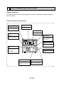
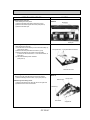
2
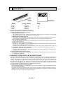
FEATURES
SWING
TIMER OFF TIMER CLOCK AUTO AUTO
CHECK SET TEMP.
FAN
START STOP SPEED
FILTER
AUTO
RETURN
CHECK MODE
TEST RUN
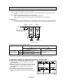
Microprocessor
Remote controller
PC24EK1
Indoor Unit
Models
PC24EK1
PC30EK1
PC36EK1
PC42EK1
Cooling capacity
24,000
31,000
36,500
42,500
Btu/h
Btu/h
Btu/h
Btu/h
SEER
10.3
10.4
10.2
10.0
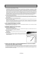
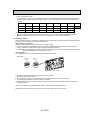
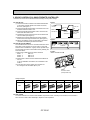
1. ADVANCED MICROPROCESSOR CONTROL
(1) Easy to use Microprocessor (remote controller)
1) Ultra-Thin Remote Controller
The streamlined, square controller is designed to blend with any kind of interior and the adoption of a sophisticated
microprocessor allows you to carry out a wide range of operations easily.
2) Attractive Liquid Crystal Display (LCD)
Units operation mode, set temperature, room temperature, timer setting, fan speed, louver operation, and air flow direction are displayed on the remote controller with the easily understood visual Liquid Crystal Display (LCD).
3) Convenient 24-Hour ON-OFF Timer
The timer allows Mr.SLIM to be switched on and off automatically at the time you set. Once the timer is set, the remaining time is shown on the LCD.
4) Self-Diagnostic Feature Indicates Faults Instantly
In the rare case when a problem occurs, the unit stops operating and the set temperature indicator changes to the selfdiagnostic indicator, indicating the location of the fault.
If the check switch is pressed twice, the unit stops operating and the check mode is initiated. The cause of the most
recent problem stored in the memory is displayed on the LCD. This is extremely useful for maintenance purposes.
5) Useful Memory Feature for Storing Instructions
The previous set value is memorized so that constant temperature control can be obtained. This is convenient when,
for example, a power failure occurs.
(2) Non-polar Two-Wire Remote Controller Cables
The non-polar, two-wire type remote controller cable is slim, installation is simple and trouble-free. Remote controller wire
can be extended up to 550 yards.
2. INNOVATIVE SYSTEM CONTROL BY MICROPROCESSORS
The most significant feature of the series PC-EK is the advanced microprocessor system control. Behind the development of
this system is the recent world-wide trend in the air conditioning of larger buildings, away from centralized duct systems in
favor of a large number of individual split type units. There are a number of reasons for this: first, costly, troublesome duct
installation is eliminated; second, the overall air conditioning balance is excellent; and third, operation cost is low since flexible control of each unit is possible. This system control was developed exclusively by Mitsubishi in the light of this demand.
Microprocessor control makes possible individual control, group control, control using two remote controllers, remote on/off
control and individual control without troublesome modifications to the equipment.
(1) Individual Control by Gathering Remote Controllers
A Series PC-EK unit is installed in each room, and the remote controller are gathered together in separate location, where
each unit is controlled individually.
Each remote controller is connected to its indoor unit by non-polar 2-wire cable to eliminate the possibility of mis-wiring.
Separation can e as much as 550 yards, making this type of control extremely easy to implement. Thermistors in the indoor
unit maintain each room at its own individually set temperature.
OC192-3
(2) Group Control by a Single Remote Controller
In an application requiring a number of air conditioner units in a large area on a single floor, up to 50 units can be centrally
controlled using a single remote controller. The remote controller controls Power ON-OFF, set temperature, fan speed,
swing louver ON-OFF timer, and auto vane position of all units of the group. Obviously, if all the units started simultaneously, the surge current would be unacceptably high. Therefore the microprocessor board of each indoor unit has a 8-toggle DIP switch that can be programmed to give sequential starting with up to 50 seconds delay. When the switch of the
remote controller is pressed, master unit comes on immediately, followed by the other units in the programmed order.
Thereafter the thermistor in each indoor unit controls compressor operation to keep the room at the set temperature.
The remote controller is connected to the indoor units by non-polar 2-wire cable. Total cable length can be as much as 550
yards. This system can be applied to the air conditioning of large offices or conference rooms, supermarkets, etc.
(3) Control Using Two Remote Controllers
Two remote controllers can be used to control either one unit or several units in group control. This makes it possible to
control units with ease either from a distance or at close range. Units operate according to the latest commands from either
remote controller.
(4) Both Remote ON/OFF Control and Individual Control
All units can be turned on and off simultaneously using the remote ON/OFF switch, and also individual units can be controlled from the remote controllers.
This system is well suited to buildings having a large number of rooms. In offices, for example, all units can be started
together to cool or heat the premises before workers arrive, operated as necessary by individual remote controllers during the day, and stopped together at the end of business.
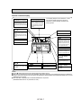
3. REDI-CHARGED REFRIGERANT SYSTEM
When refrigerant tubing is 100ft or less, it is unnecessary to charge additional refrigerant. This can contribute to enhance
installation quality and reduce installation time.
4. MAXIMUM COMFORT AIR CONDITIONING
(1) Indoor Unit Chargeable Air Outlet
PC-EK series have changeable air outlet.
Downward air flow can be obtained at an angle up to 30-. Upward air flow at angle of 10- is able to stretch cool air in a
room. This function enables comfortable air distribution.
(2) Swing Flow Louvers
The swing Flow Louvers automatically change the air flow direction for desirable
air distribution.
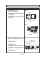
(3) Fresh-Air Intake
The PC-EK series also has fresh air intake, providing more comfortable, healthful air conditioning through better ventilation. The rear panel has a knock-out for
the intake of fresh air.
5. STABLE COOLING EVEN AT OUTDOOR TEMPERATURES AS LOW AS 23--F MAKES
YEAR-ROUND AIR-CONDITIONING POSSIBLE
The microprocessor automatically adjusts fan speed in accordance with outdoor temperature to maintain the coolant at an
even condensing temperature. The result is smooth, efficient cooling even when temperatures outdoors drop as low as 23-F.
This makes the unit ideal for a wide range of specialized cooling needs, such as rooms with many office machines or computers and areas subject to strong sunlight.
OC192-4
6. DRAIN PUMP FOR EASY PIPE CONNECTION (Option)
This mechanism, with its capacity to raise drain water 20” above the ceiling line, is convenient for removing water and avoiding piping contact with beams, etc.
Note : This can not be mounted in the unit.
7. SLIM, COMPACT AND SPACE SAVING
(1) Space Saving Design
Because the PC-EK series indoor units are designed to be suspended from the ceiling, valuable floor space and wall surfaces are not used. The unit is only 7-11/16” high and 50-7/16” wide (PC24EK).
The outdoor units are also slim line, with a depth dimension of only 11-5/8” (PU24EK).
(2) Flush-To-The-Wall Installation
Since the units in the PC-EK series are installed flush against the back wall, connection pipes are hidden. This gives the
room a touch of sleek sophistication.
8. EASY INSTALLATION
Installation is simple, thanks to the easy-connection refrigerant lines. As all outdoor units are charged for 100’ of line set and
tested at the factory, there’s no need for special on-site work.
The indoor unit is easy to mount and requires only a minimum of wiring, saving your time, labor, and money.
9. HIGH RELIABILITY AND EASY SERVICING
In addition to the self-diagnostic function, units are also equipped with a 3-minute time delay mechanism, an auto restart function, an emergency operation function, a test run switch, etc., to assure high reliability and easy servicing.
10. ECONOMICAL AND EFFICIENT OPERATION
• Mitsubishi exclusive LCD indicators show the temperature selected and the current room temperature. This system ensures
full protection against excessive cooling.
• The Mitsubishi Electric split-type air-to-air PC models feature highly precise compressors with large-capacity heat exchangers for efficient operation.
11. NITROGEN GAS IS CHARGED TO INDOOR UNIT
Indoor units of this series are changed with nitrogen gas (N2) instead of (R22) before shipment from the factory.
OC192-5
3
PART NAMES AND FUNCTIONS
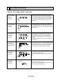
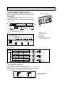
Remote controller
Once the controls are set, the same operation mode can be repeated by simply pressing the
ON / OFF button.
Remote controller operation buttons
CLOCK/TIMER button
TIMER ON/OFF button
This switches between continuous
operation and the timer operation.
This sets or switches the current
time,start time and stop time.
FAN SPEED button
This sets the fan speed.
OPERATION MODE
button
ON/OFF button
Press this button to switch the cooling, electronic dry (Dehumidify),fan
modes.
This switches between the operation and stop modes each time it is
press. The lamp on this button
lights during operation.
F
AIR DISCHARGE
button
DRY COOL TIMER OFF TIMER CLOCK AUTO AUTO
FAN CHECK SET TEMP.
START STOP FAN
SPEED
SET TEMPERATURE
button
This sets the room temperature.
The temperature setting can be performed in 2-F units.
Setting range :
Cooling 65-F to 87-F
This adjusts the vertical angle of the
ventilation.
MODE
TIMER ON/OFF CLOCK/TIMER FAN SPEED AIR DISCHARGE FILTER
AIR SWEEP
SET TEMP.
TIMER SET
CHECK
TEST RUN
REMOTE CONTROLLER
PAR-JC250KUS
FILTER button
This resets the filter service indication display.
AIR SWEEP button
CHECK-TEST RUN button
This switches the horizontal fan motion
(Swing louver) ON and OFF.
(This button does not operate in this
models.)
Only press this button to perform an
inspection check or test operation.
Do not use it for normal operation.
OC192-6
Remote controller display
CENTRALLY
CONTROLLED display
This indicates when the unit is controlled by optional features such as
central control type remote controller.
TIMER
In this display example on the bottom left, a condition where all display lamps light is shown for
explanation purposes although this differs from
actual operation.
CLOCK display
The current time , start time and stop
time can be displayed in ten second
intervals by pressing the time switch
button. The start time or stop time is
always displayed during the timer
operation.
display
FAN SPEED display
This indicates when the continuous
operation and time operation modes
are set.
It also display the time for the timer
operation at the same time as when
it is set.
The selected fan speed is displayed.
F
F
OPERATION MODE display
DRY COOL TIMER OFF TIMER CLOCK AUTO AUTO
FAN CHECK SET TEMP.
START STOP FAN
SPEED
This indicates the operation mode.
MODE
TIMER ON/OFF CLOCK/TIMER FAN SPEED AIR DISCHARGE FILTER
AIR SWEEP
SET TEMP.
TIMER SET
display
The temperature of the return air is
displayed during operation. The display range is 47°F to 97°F. The display flashes 47°F when the actual
temperature is less than 47°F and
flashes 97°F when the actual temperature is greater than 97°F.
CHECK
TEST RUN
REMOTE CONTROLLER
PAR-JC250KUS
Operation lamp
This lamp lights during operation,
goes off when the unit stops and
flashes when a malfunction occurs.
CHECK MODE
TEST RUN
CHECK
display
This indicates when a malfunction
has occurred in the unit which should
be checked.
display
This display lights in the check mode
or when a test operation is performed.
F display
This displays the selected setting
temperature.
display
FILTER
This lamp lights when electricity is
supplied to the unit.
display
This lamp lights when the filter needs
to be cleaned.
Caution
● Only the
display lights when the unit is stopped and power supplied to the unit.
● When power is turned ON for the first time the (CENTRAL CTRL) display appears to go off momentarily but this is not a malfunction.
● When the central control remote control unit, which is sold separately, is used the ON-OFF button,OPERATION MODE button and SET
TEMP. button do not operate.
● “NOT AVAILABLE” is displayed when the AIR DISCHARGE button are pressed.
(AIR DISCHARGE function is not provided for PC series.)
OC192-7
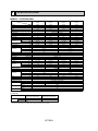
4
SPECIFICATIONS
MODELS : PC24/30/36/42EK1
Model
PC24EK1
PC30EK1
24,000
2.43
9.9
10.3
PC24EK1
31,000
36,500
3.10
3.80
10.0
9.6
10.4
10.2
PC30EK1
PC36EK1
Munsell 2.5Y 8/0.3 & N2 115, 1, 60
15
15
3.0
3.0
1.8
2.1
1,050-850
1,270-990
900-730
1,100-860
9.6
11.1
50-43
52-44
1
1
PC36EK1
PC42EK1
Item
Capacity
Power consumption
EER
SEER
INDOOR UNIT MODEL
External finish
Power supply
Max. fuse size (time delay)
Min ampacity
Fan motor
Dry
Airflow Hi-Lo
Wet
Moisture removal
Sound level Hi-Lo
Unit drain pipe OD.
W
D
Dimensions
H
Weight
OUTDOOR UNIT MODEL
External finish
Power supply
Max. fuse size (time delay)
Min. ampacity
Fan motor
Model
Compressor
❈ 1
❈ 1
❈ 1
Btu/h
kW
V, Phase, Hz
A
A
F.L.A.
CFM
CFM
Pints/h
dB
in.
in.
in.
in.
Ib
PU24EK1
PU30EK1
PU36EK1
PU42EK2
Munsell 5Y7/1
208/230, 1, 60
V, Phase, Hz
A
A
F.L.A
Crankcase heater
Refrigerant control
Sound level
W
D
H
dB
in.
in.
in.
Ib.
Weight
REMOTE CONTROLLER
Control voltage (by built-in
transformer)
REFRIGERANT PIPING
Liquid
Pipe size
Gas
Indoors
Connection method
Outdoors
Between the indoor Height
Piping length
& outdoor units
20
16
0.65+0.65
NH33NBD
11.5
54
016/0.17 (33/39)
55
33-1/4
11-5/8
49-9/16
207
in.
in.
3/8
5/8
ft
fr
*
208
220
40
27
0.8+0.8
NH569NXA
20
105
0.16/0.17 (33/39)
56
38-3/16
13-9/16
49-9/16
With indoor unit
Indoor unit - remote controller : DC12V, Indoor unit - outdoor unit : DC12V
Not supplied (optional parts)
1/2
3/4
Flared
Flared
164
164
Operating range
Cooling
62-1/4
26-13/16
10-1/8
115
30
30
20
22
0.65+0.65
0.75+0.75
NH41NAD
NH47NAD
14.0
17.5
73
87
0.16/0.17 (33/39)
0.16/0.17 (33/39)
Capillary tube
55
55
NOTES : ❈ 1.Rating conditions —indoor : 80°FDB, 67°FWB outdoor : 95°FDB,75°FWB.
Maximum
Minimum
15
3.0
2.4
1,270-990
1,100-860
12.6
52-44
1
15
3.0
1.8
1,050-850
900-730
7.2
50-43
1
50-7/16
26-13/16
10-1/8
93
R.L.A
L.R.A
A(W)
Dimensions
42,500
4.40
9.7
10.0
PC42EK1
Indoor intake air temperature
Outdoor intake air temperature
95°FDB, 71°FWB
67°FDB, 57°FWB
115°FDB
0°FDB *
In case of the wind baffle is installed.
(In case of the wind baffle is not installed, the minimum temperature will be 23°FDB.)
OC192-8
260
5
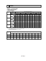
DATA
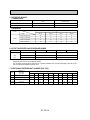
MODELS : PC24/30/36/42EK1
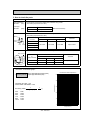
1. PERFORMANCE DATA
1) COOLING CAPACITY
Indoor air
Models
PC24EK1
PC30EK1
PC36EK1
PC42EK1
Airflow
(CFM)
B.F
900
0.14
900
0.15
1,100
0.12
1,100
0.12
Outdoor intake air DB temperature(°F)
IWB
(°F)
75
85
95
105
115
TC
SHC
TPC
TC
SHC
TPC
TC
SHC
TPC
TC
SHC
TPC
TC
SHC
TPC
71
27.8
15.6
2.10
20.7
15.4
2.30
25.8
15.1
2.49
24.8
14.9
2.70
23.6
14.6
2.90
67
26.2
18.3
2.05
25.2
17.9
2.24
24.0
17.5
2.43
23.2
17.2
2.62
22.2
16.8
2.82
63
24.5
20.4
2.00
23.6
19.9
2.19
22.8
19.5
2.37
21.8
19.0
2.56
20.8
18.5
2.75
71
35.9
17.7
2.67
34.5
17.3
2.90
33.1
16.9
3.18
31.7
16.6
3.45
30.2
16.1
3.73
67
33.3
21.1
2.60
32.3
20.6
2.82
31.0
20.1
3.10
29.6
19.5
3.35
28.2
19.0
3.62
63
31.2
23.8
2.55
30.2
23.2
2.78
29.0
22.6
3.02
27.6
21.8
3.28
26.2
21.1
3.55
71
42.3
21.6
3.23
40.9
21.2
3.53
39.3
20.7
3.88
37.5
20.3
4.25
35.7
19.8
4.62
67
39.3
25.5
3.18
37.9
24.9
3.46
36.5
24.3
3.80
34.9
23.7
4.13
33.3
23.1
4.49
63
36.7
28.6
3.12
35.5
28.0
3.38
33.9
27.1
3.70
32.5
26.4
4.03
31.0
25.5
4.38
71
50.2
23.8
4.00
48.2
23.2
4.25
45.8
22.6
4.55
43.5
21.9
4.85
41.1
21.2
5.25
67
46.4
28.5
3.90
44.6
27.7
4.15
42.5
26.8
4.40
40.3
25.9
4.70
38.1
25.0
5.00
63
43.3
32.2
3.80
41.5
31.2
4.00
39.5
30.1
4.25
37.3
28.9
4.50
35.1
27.6
4.75
Notes 1. B.F. : Bypass Factor, IWB : Intake air wet-bulb temperature
TC : Total Capacity (x103 Btu/h), SHC : Sensible Heat Capacity (x103 Btu/h)
TPC : Total Power Consumption (kW)
2. SHC is based on 80°FDB of indoor intake air temperature.
Refrigerant piping length (one way)
MODEL
25ft (std)
40ft
55ft
70ft
85ft
100ft
115ft
130ft
150ft
164ft
PC24EK1
1.0
0.981
0.968
0.952
0.940
0.925
0.913
0.900
0.886
0.874
PC30EK1
1.0
0.981
0.986
0.952
0.940
0.925
0.913
0.900
0.886
0.874
PC36EK1
1.0
0.981
0.968
0.952
0.940
0.925
0.913
0.900
0.886
0.874
PC42EK1
1.0
0.975
0.955
0.935
0.918
0.900
0.884
0.869
0.855
0.840
OC192-9
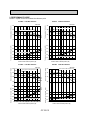
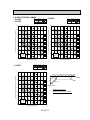
2. PERFORMANCE CURVE
NOTES : A point on the curve shows the reference point.
PC30EK1 COOLING CAPACITY
Indoor intake air WB temperature ( F)
30
24
71
67
63
18
3.5
71
67
63
3.0
2.5
Indoor intake air WB temperature ( F)
2.0
1.5
23
32 35
45
55
65(67) 75
85
95
105 115
Outdoor intake air DB temperature ( F)
Total capacity (x10 3 Btu/h)
SHF=0.76
36
Total power consumption (kW)
Total power consumption (kW)
Total capacity (x10 3 Btu/h)
PC24EK1 COOLING CAPACITY
Indoor intake air WB temperature ( F)
36
24
4.0
71
67
63
3.5
3.0
2.5
Indoor intake air WB temperature ( F)
2.0
23
32 35
45
55
65(67) 75
85
95
105 115
Outdoor intake air DB temperature ( F)
PC42EK1 COOLING CAPACITY
SHF=0.74
Indoor intake air WB temperature ( F)
42
36
71
67
63
30
Total capacity (x10 3 Btu/h)
Total capacity (x10 3 Btu/h)
71
67
63
30
PC36EK1 COOLING CAPACITY
48
SHF=0.68
42
SHF=0.65
54
Indoor intake air WB temperature ( F)
48
42
71
67
36
63
71
67
63
4.5
4.0
3.5
3.0
Indoor intake air WB temperature ( F)
2.5
23
32 35
45
55
65(67) 75
85
95
Outdoor intake air DB temperature ( F)
105 115
Total power consumption (kW)
Total power consumption (kW)
5.0
6.0
71
67
63
5.0
4.0
Indoor intake air WB temperature ( F)
3.0
23
OC192-10
32 35
45
55
65(67) 75
85
95
Outdoor intake air DB temperature ( F)
105 115
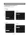
3. CONDENSING PRESSURE AND SUCTION PRESSURE
Data is based on the condition of indoor humidity 50%.
Air flow should be set at HI.
A point on the curve shows the reference point.
< Cooling mode>
PC24EK1
PC24EK1
86 (psi.G)
100
80
75
90
70
Condensing pressure
(psi.G)
350
340
330
320
310
300
290
280
270
260
250
240
230
220
210
200
190 Indoor DB temperature( F)
180
170
160
150
30
40
50
60
70
80
90
Outdoor ambient temperature
86
80
Suction pressure
80 Indoor DB temperature( F)
75
70
70
60
50
40
30
100
20
110
DB( F)
30
40
50
60
70
80
90
Outdoor ambient temperature
100
110
DB( F)
PC30EK1
PC30EK1
86
80 (psi.G)
75
100
70
Condensing pressure
(psi.G)
350
340
330
320
310
300
290
280
270
260
250
240
230
220
210
200
190 Indoor DB temperature( F)
180
170
160
150
30
40
50
60
70
80
90
Outdoor ambient temperature
90
86
80
75
Suction pressure
80
Indoor DB temperature( F)
70
70
60
50
40
30
100
110
DB( F)
OC192-11
20
30
40
50
60
70
80
90
Outdoor ambient temperature
100
110
DB( F)
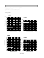
Data is based on the condition of indoor humidity 50%.
Air flow should be set at HI.
A point on the curve shows the reference point.
< Cooling mode>
PC36EK1
PC36EK1
86
80 (psi.G)
75
100
70
Condensing pressure
(psi.G)
350
340
330
320
310
300
290
280
270
260
250
240
230
220
210
200
190 Indoor DB temperature( F)
180
170
160
150
30
40
50
60
70
80
90
Outdoor ambient temperature
90
Suction pressure
80
86
80
Indoor DB temperature( F)
75
70
70
60
50
40
30
100
20
110
DB( F)
30
40
50
60
70
80
90
Outdoor ambient temperature
100
110
DB( F)
PC42EK1
PC42EK1
86 (psi.G)
80
100
75
70
90
Condensing pressure
(psi.G)
350
340
330
320
310
300
290
280
270
260
250
240
230
220
210
200
190 Indoor DB temperature( F)
180
170
160
150
30
40
50
60
70
80
90
Outdoor ambient temperature
86
80
Suction pressure
80
70
75
Indoor DB temperature( F)
70
60
50
40
30
100
110
DB( F)
20
30
OC192-12
40
50
60
70
80
90
Outdoor ambient temperature
100
110
DB( F)
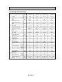
4. STANDARD OPERATION DATA
Model
PC24EK1
PC30EK1
PC36EK1
PC42EK1
Unit
Cooling
Cooling
Cooling
Cooling
Btu / h
24,000
31,000
36,500
42,500
SHF
—
0.76
0.68
0.74
0.65
Input
kW
2.43
3.1
3.8
4.4
INDOOR UNIT MODEL
PC24EK1
PC30EK1
PC36EK1
PC42EK1
Power supply (V, phase, Hz)
115, 1, 60
115, 1, 60
115, 1, 60
115, 1, 60
kW
0.2
0.2
0.22
0.26
A
1.8
1.8
2.1
2.4
OUTDOOR UNIT MODEL
PU24EK1
PU30EK1
PU36EK1
PU42EK2
Power supply (V, phase, Hz)
208/230, 1, 60
208/230, 1, 60
208/230, 1, 60
208/230, 1, 60
kW
2.23
2.9
3.58
4.14
Item
Total
Capacity
Electrical circuit
Input
Fan current
Refrigerant circuit
Input
Comp. current
A
11.5
14.0
17.5
20.0
Fan current
A
0.65+0.65
0.65+0.65
0.75+0.75
0.8+0.8
Condensing pressure
psi-G
237
236
250
237
Suction pressure
psi-G
78
75
81
71
Discharge temp.
°F
158
167
165
168
Condensing temp.
°F
113
113
117
113
Suction temp.
°F
49
46
50
46
Ref. pipe length
ft
25
25
25
25
—
9 lbs 15 oz
10 lbs 2 oz
10 lbs 9oz
12 lbs 9oz
DB
°F
80
80
80
80
WB
°F
67
67
67
67
DB
°F
60
57
59
56
WB
°F
58
55
57
55
Fan speed (High)
rpm
1,410
1,410
1,490
1,490
Airflow (High)
CFM
900
900
1,100
1,100
DB
°F
95
95
95
95
WB
°F
—
—
—
—
Refrigerant charge
Intake air temperature
Outdoor side
Indoor side
Discharge air temperature
Intake air temperature
Fan speed upper / lower
rpm
Airflow
CFM
750
750
3,170
OC192-13
750
3,170
750
760
3,350
760
840
3,350
840
5. OPERATING RANGE
1) POWER SUPPLY
Rating
Allowable voltage
Indoor unit
115V 1 phase 60Hz
Min. 103V — Max. 127V
Outdoor unit
208/230V 1 phase 60Hz
Min. 198V — Max. 253V
2) OPERATION
Intake air temperature
Indoor
Outdoor
DB (°F)
WB (°F)
DB (°F)
WB (°F)
Standard temperature
80
67
95
75
Maximum temperature
95
71
115
75
Minimum temperature
67
57
23
—
Maximum humidity
80
75
80
75
PC30EK1
PC36EK1
Function
Condition
Cooling
6. OUTLET AIR SPEED AND COVERAGE RANGE
Standard
Airflow
height
Air speed
(8.2ft)
Coverage range
PC24EK1
(CFM)
1,050
1,270
(ft / sec.)
17.0
16.5
43
48
(ft)
PC42EK1
● The air coverage range is the value up to the position where the air speed is 0.8ft/sec. when air is blown out
horizontally from the unit at the High fan setting.
The coverage range should be used only as a general guideline since it varies according to the size of the
room and furniture installed inside the room.
7. ADDITIONAL REFRIGERANT CHARGE (R22 (OZ))
Outdoor
unit
precharged
(up to 100ft)
25ft
40ft
55ft
70ft
85ft
100ft
PC24EK1
9 lbs 15 oz
0
0
0
0
0
PC30EK1
10 lbs 2 oz
0
0
0
0
PC36EK1
10 lbs 9 oz
0
0
0
PC42EK1
12 lbs 9 oz
0
0
0
Model
(over way)
Refrigerant
piping
length
115ft
130ft
150ft
164ft
0
2
4
7
9
0
0
5
10
16
20
0
0
0
5
10
16
20
0
0
0
5
10
16
20
OC192-14
8. NOISE CRITERION CURVES
NOTCH
PC24EK1
Hi
PC30EK1
Lo
PC36EK1
NOTCH
SPL(db(A))
50
Hi
51
43
Lo
45
SPL(db(A))
LINE
90
90
80
80
70
NC-70
60
NC-60
50
NC-50
40
NC-40
30
NC-30
20
OCTAVE BAND SOUND PRESSURE LEVEL, dB re 0.002 MICRO BAR
OCTAVE BAND SOUND PRESSURE LEVEL, dB re 0.002 MICRO BAR
70
NC-70
60
NC-60
50
NC-50
40
NC-40
30
NC-30
APPROXIMATE
THRESHOLD OF
HEARING FOR
CONTINUOUS
NOISE
20
APPROXIMATE
THRESHOLD OF
HEARING FOR
CONTINUOUS
NOISE
LINE
NC-20
NC-20
10
10
63
125
250
500
1000
2000
4000
63
8000
125
PC42EK1
250
500
1000
2000
4000
8000
BAND CENTER FREQUENCIES, Hz
BAND CENTER FREQUENCIES, Hz
NOTCH
SPL(db(A))
Hi
51
Lo
45
LINE
OCTAVE BAND SOUND PRESSURE LEVEL, dB re 0.002 MICRO BAR
90
80
ceiling
1m
70
NC-70
1m
about 1.4m
60
NC-60
MICROPHONE
50
NC-50
Ambient temperature 80°F
40
NC-40
30
NC-30
20
APPROXIMATE
THRESHOLD OF
HEARING FOR
CONTINUOUS
NOISE
NC-20
10
63
125
250
500
1000
2000
4000
8000
BAND CENTER FREQUENCIES, Hz
OC192-15
Test conditions are based on JIS Z8731
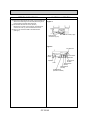
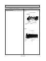
unit
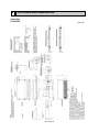
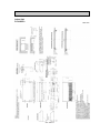
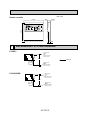
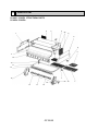
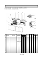
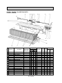
1Drainage pipe connection (1inch dia.I.D.)
2Knock out hole for rear drainage piping arrangement
3Refrigerant-pipe flared connection 5/8 (PC24EK1), 3/4F (PC30EK1)
4Refrigerant-pipe flared connection 3/8 (PC24EK1), 1/2F (PC30EK1)
5Knock out hole for rear refrigerant-piping arrangement
6Knock out hole for upper refrigerant-piping arrangement
7Knock out hole for right piping (refrigerant, drainage and wiring)
8Knock out hole for wiring arrangement
9Wall hole for wiring arrangement
0Ceiling hole for piping arrangement
1Terminal bed for power line
2Terminal bed for indoor and outdoor units connection
3Terminal bed for Remote controller
4Knock out hole for fresh air intake
6
OUTLINES AND DIMENSIONS
Indoor Unit
PC24/30EK1
Unit : inch
OC192-16
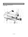
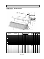
Indoor Unit
PC36/42EK1
Unit : inch
OC192-17
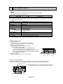
Unit : inch
Remote controller
5-1/8
3/32
23/32
SWING
TIMER OFF TIMER CLOCK AUTO AUTO
CHECK SET TEMP.
FAN
START STOP SPEED
FILTER
CHECK MODE
TEST RUN
4-3/4
AUTO
RETURN
3/4
7
REFRIGERANT SYSTEM DIAGRAM
PC24EK1
Refrigerant pipe
(option)
{5/8"
(with heat insulator)
Flared connection
Strainer
Indoor coil
thermistor
TH2
COOLING
Refrigerant pipe
(option)
{3/8"
(with heat insulator)
Flared connection
Distributor
PC30/36/42EK1
Refrigerant pipe
(option)
{3/4"
(with heat insulator)
Flared connection
Strainer
Indoor coil
thermistor
TH2
Distributor
Refrigerant pipe
(option)
{1/2"
(with heat insulator)
Flared connection
OC192-18
8
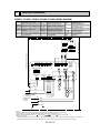
WIRING DIAGRAM
MODELS PC24EK1 PC30EK1 PC36EK1 PC42EK1 WIRING DIAGRAM
SYMBOL
NAME
NAME
SYMBOL
R.B
REMOTE CONTROLLER BOARD
FAN MOTOR CAPACITOR
C
CN1<R.B> PROGRAM TIMER CONNECTOR SW1<I.B> MODE SELECTOR SWITCH
CN2<R.B> REMOTE SWITCH CONNECTOR SW2<I.B> ADDRESS SELECTOR SWITCH
CN51<I.B> CENTRALLY CONTROL CONNECTOR SW3<I.B> EMERGENCY OPERATION SWITCH
SW5<I.B> MODEL SELECTOR SWITCH
CN2L<I.B> LOSSNAY CONNECTOR
SW6<I.B> MODEL SELECTOR SWITCH
FUSE (6A)
F<I.B>
INDOOR CONTROLLER BOARD SW17<R.B> ADDRESS SELECTOR SWITCH
I.B
FAN MOTOR (INNER THERMOSTAT) SW18<R.B> FUNCTION SELECTOR SWITCH
MF
T
TRANSFORMER
LOUVER MOTOR
ML
SYMBOL
NAME
TB1~6
TERMINAL BLOCK
TH1
ROOM TEMPERATURE
THERMISTOR(32°F/15k", 77°F/5.4k")
TH2
PIPE TEMPERATURE
THERMISTOR(32°F/15k", 77°F/5.4k")
X2<I.B>
LOUVER MOTOR RELAY
X5<I.B>
FAN MOTOR RELAY
X6<I.B>
FAN MOTOR RELAY
ZNR
VARISTOR
R.B
TB6
1
87654321
OFF
ON
2
REMOTE CONTROLLER
SW18
CN1
TH1
TH2
INDOOR UNIT
TRANSMISSION WIRES DC12V
5 4 3 2 1
SW17
CN2
OFF
ON
3 2 1
87654321
I.B
SW3
CN2L
OFF 5 4 3 2 1 2 1 2 1
ON
CN50
CN20 CN21
LOSSNAY 654321 4321 4321 10987654321 4321
DRAIN
INTAKE PIPE
SW2 SW5 SW6
SW1
REMOCON POWER
CN40
CENTRALLY
CONTROL
CN51
X6 X5
X2
4 3 2 1
X2
TO OUTDOOR UNIT
CONNECTING WIRES
DC12V(polar)
TB1
L1
POWER SUPPLY
115V 60Hz
N
1 PHASE
2 3
1
S R
WHT
RED
M0
WHT
YLW
M2
T
AC
115V
GRN
MF
ORN
1
M3
RED
ORN
LOUVER
GRN
TB2
2
F
ML
AC11V
BLU
WHT
1
AC15.5V
BLU
RED
TB3
2
ZNR
BLK
BLU
RED
WHT
4 3 2 1 TRANS
RED
RED
BRN
BRN
3 2 1
GRY
GRY
TO REMOCON OUTDOOR
CN30
CN22
2 1
X5
X6
TRANS
CN4T
5
6
C
RED
WHT
GROUND
NOTES:
1.Since the outdoor side electric wiring may change be sure to check the outdoor unit electric wiring for servicing.
2.Indoor and outdoor connecting wires are made with polarities,make wiring matching terminals.
3.Symbols used in wiring diagram above are,
:Terminal block, ,
:connector, :PC board insertion tab.
4.Emergency operation
If a trouble occurs with either the remote controller or the indoor microcomputer and no other trouble exists,emergency operation for cooling can be performed by changing the setting of dip switch (SW3(I.B)) on the indoor controller board (emergency dry operation is not possible).
OC192-19
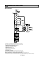
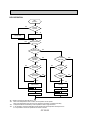
9
OPERATION FLOW-CHART
MAIN OPERATION
START
Power circuit
breaker
1
YES
NO
YES
Check SW
ON twice
NO
Operation SW
ON
1
YES
YES
NO
“OFF” timer
NO
NO
“ON” timer
Set time
complete
NO
YES
Set time
complete
NO
YES
YES
2
NO
Trouble
STOP
Remote controller
operation display
YES
Trouble STOP
Operating mode
(COOL)
PROTECTION DEVICE
SELF HOLD
Operating mode
(DRY)
3
Remote controller
indicator lamp OFF
Remote controller
trouble display
YES
YES
COOL operation
NO
PROTECTION DEVICE
SELF HOLD RELEASE
DRY operation
NO
6
FAN operation
Indoor side
4
Fan STOP
Auxiliary heater OFF
Outdoor side
5
Compressor OFF
Fan STOP
❈1 In addition, the centralized and remote control can be operated.
❈2 The modes which indicate the sources of trouble are listed below.
● E0=Signal transmitting/receiving error
● P1=Room temperature thermistor malfunction
● P2=Indoor coil thermistor malfunction
● P4=Drain sensor malfunction
● P5=Drain over flow
● P6=Coil frost/overheat protection
● P7=System error
● P8=Outdoor unit trouble
❈3 The CHECK switch will show if an error has occurred in the past.
❈4 Fan runs on low speed for 1 minute in order to remove overheat air.
❈5 The 3-minute (6 minutes … heating mode) time-delay functions after compressor stops.
❈6 FAN or AUTO mode is selected by the indoor dip switch setting.
❈7 In FAN mode, fan speed and vane operation depend on the remote controller setting. (Compressor is OFF.)
OC192-20
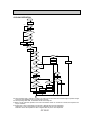
COOLING OPERATION
COOL operation
Four-way valve/OFF
NO
Initial
COOLING
8
YES
Vane initial
setting
NO
Vane
60 deg downward angle
70 deg downward angle
YES
NO
Fan speed
LOW
YES
NO
Vane setting notch
Downward discharge
1 hour
YES
Vane horizontal
airflow
NO
9
Compressor
thermostat
ON
YES
NO
Allowance
cancel
NO
YES
3-minute
time delay
NO
6-minute
time delay
YES
NO
NO
3-minute
compressor
operation
10
YES
Allowance
period
NO
6 minute
time delay
Allowance set
Coil frost protection
YES
YES
Coil frost
prevention
NO
11
NO
Cooling area
YES
NO
10-minute
compressor operation
NO
1 min continue
YES
YES
Allowance cancel
FAN speed
LOW
Coil frost
protection
YES
NO
NO
Indoor coil
tempreature is
50-F or higher
16-minute
compressor
operation
YES
Indoor pipe
temperature is
34-F or lower
YES
FAN speed
LOW 5 min
elapse
NO
YES
YES
NO
Coil frost
prevention
NO
Outdoor unit
trouble
3-minute
time delay
Coil frost
prevention release
Compressor ON
Compressor OFF
1
❈8 When operation stops or changes to cooling or dry mode, the auto vane turns to a horizontal angle. If operation changes
during auto vane SWING, the auto vane will continue to swing.
❈9 When operating TEST RUN, the thermostat will be continuously ON.
❈10After 3 minute compressor operation, if the indoor coil thermistor reads -5°F or below for 3 minutes, the compressor will
stop for 6 minutes.
❈11Cooling area : Indoor coil temperature is more than 5 degrees above the room temperature.
Heating area : Indoor coil temperature is more than 5 degrees below the room temperature.
FAN area : Indoor coil temperature is within 5 degrees either way of the room temperature.
OC192-21
DRY OPERATION
DRY
operation
NO
Initial dry
operation
❈8
YES
Vane
setting notch
Vane initial setting
YES
❈12
Room temperature is
64°F or lower
NO
NO
During
compressor ON
YES
3-minute
compressor
operation
NO
NO
YES
NO
YES
3-minute
time delay
❈9
Compressor &
thermostat ON
YES
Compressor &
thermostat
ON
❈9
NO
YES
NO
Compressor ON
time completes
10-minute
compressor
OFF
NO
YES
YES
❈13
10-minute compressor
OFF timer start
Compressor ON
time set
Compressor OFF
Compressor ON
❈14
Fan STOP
❈14
Fan speed LOW
1
❈8 ~ 9 Refer to the previous page OC192-21.
❈12 When room temperature is 64°F or below, the compressor cannot operate.
When room temperature rises over 64°F, the compressor starts after a 3-minute time delay.
❈13 Compressor ON time is decided by room temperature. Refer to page OC192-27
❈14 In dry operation, compressor ON makes the fan speed LOW and compressor OFF stops the fan.
It is not possible to set the fan speed with the remote controller
OC192-22
10
MICROPROCESSOR CONTROL
1.OUTLINE OF MICROPROCESSOR CONTROL
Remote controller board
INPUT to remote controller
● OFF-ON switching.
● COOL/DRY-FAN selector switching.
● Thermostat setting.
● TIMER mode selector-switching and Timer
setting.
● HIGH-LOW fan speed switching.
● Swing louver (AIR SWEEP) switching.
● TEST RUN switching.
● CHECK mode switching.
(Self diagnostic trouble shooting)
Remote controller
● LCD indicator
TIMER OFF TIMER CLOCK AUTO AUTO
CHECK SET TEMP.
Non-polar, two-wire cable
maximum length 550 yards
Signal
Indoor controller board
● Receives orders from remote controller and temperature data from indoor unit.
● Processes orders and data.
● Controls indoor and outdoor operation.
● Self diagnostic function.
w System control operation.
w Emergency operation.
w Set by dip switch on indoor controller board.
● Transmits the power to remote controller.
1
● Swing louver control ON-OFF.
● Emergency stop.
Polar two-wire cable
Outdoor unit
● Compressor protection
device working
● Fan speed control.
● Crankcase heater control
ON-OFF.
● Self diagnostic function
12VDC
Independent Control of
Outdoor Unit
1
2
OC192-23
2
OUTPUT to outdoor unit
OUTPUT to indoor unit
FILTER
TEST RUN
INPUT from indoor unit
● Room temperature thermistor (TH1)
● Pipe temperature thermistor (TH2)
FAN
START STOP SPEED
CHECK MODE
12VDC
Indoor
unit
● Processes and transmits
orders.
OUTPUT to remote controller
● Compressor and
outdoor fan : ONOFF
2. INDOOR UNIT CONTROL
2-1 COOL operation
<How to operate>
1 Press POWER ON/OFF button.
2 Press the MODE button to display COOL.
3 Press the SET TEMP. button to set the desired temperature.
NOTE: Set temperature changes 2°F when the SET TEMP. button
is pressed one time.
Cooling 65 to 87°F.
SWING
TIMER OFF TIMER CLOCK AUTO AUTO
CHECK SET TEMP.
FAN
START STOP SPEED
FILTER
AUTO
RETURN
CHECK MODE
TEST RUN
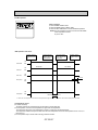
<COOL operation time chart>
Operation starts by
P O W E R b u t t o n
ON.
Room temperature
becomes equal to
set temperature.
Room temperature
rises above set
temperature.
Operation stops by
P O W E R b u t t o n
OFF.
ON
Thermostat
OFF
ON
Indoor fan
LOW or HIGH
LOW or HIGH
OFF
ON
Auto vane
OFF
3 minutes
ON
Drain pump
OFF
ON
Compressor
OFF
Minimum 3 minutes
w1
w1 Even if the room temperature rise above the set temperature during this period, the compressor will not start until this period has ended.
(1) Compressor control
1 3-minute time delay
To prevent overload, the compressor will not start within 3 minutes after stop.
2 The compressor runs when room temperature is higher than set temperature.
The compressor stops when room temperature is equal to or lower than the set temperature.
The compressor maintains the previous state when the room temperature minus the set temperature is 0 degrees or more,
or lower than 2 degrees.
3 The compressor stops in check mode or during protective functions.
4 Coil frost prevention
To prevent indoor coil frost, the compressor will stop when the indoor coil thermistor (TH2) reads 34°F or below after the
compressor has been continuously operated for at least 16 minutes or more. When the indoor coil temperature rises to 50°F
or above, the compressor will start in a 3-minute(w2) time delay.
w2 When the indoor coil temperature is 30°F or less, the compressor starts in 6 minutes.
NOTE : By turning OFF the dip switch SW1-3 on indoor controller board, the start temperature of coil frost prevention changes
from 34°F to 36°F.
OC192-24
5 Coil frost protection
When indoor coil temperature becomes 5°F or below,coil frost protection will proceed as follows.
<Start condition>
After the compressor has been continuously operated for 3 minutes or more,and the indoor coil temperature has been
5°F or below for 3 minutes,the coil frost protection will start.
<Coil frost protection>
Compressor stops for 6 minutes,and then restarts.
lf the start condition is satisfied again during the first 10 minutes of compressor operation,both the indoor and outdoor
units stop,displaying a check code of “P6” on the remote controller.
<Termination conditions>
Coil frost protection is released when the start condition is not satisfied again during the allowance, or when the COOL
mode stops or changes to another mode.
(2) Indoor fan control
Indoor fan speed LOW/HIGH depends on the remote controller setting.
However, if an outdoor unit abnormality is detected, the indoor fan speed will be LOW, regardless of the remote controller
setting.
( i ) Fan speed LOW/HIGH depends on the remote controller setting regardless of the thermostat ON/OFF.
(ii) Fan speed will remain on LOW if an abnormality in outdoor unit is detected. (5 minutes)
NOTE : Fan stops immediately if the unit stops or the check mode is started.
(3) Auto vane control
1) Frequency judgement
(1
When the unit operates for the first time after the circuit breaker turned to ON, the frequency, 50Hz or 60Hz, is judged by
the horizontality sensing switch. If the frequency cannot be judged immediately for some reason, the sensing operation
continues for 10 minutes with the vane motor at ON.
If the frequency cannot be judged yet after 10-minute sensing, the vane motor turns to OFF. But the AIR DISCHARGE
DIRECTION display continues to be indicated.
2) During cooling operation
(2
When the cooling operation starts, the horizontal discharge is automatically set. However,
<Remote controller display>
the desired discharge among four modes below-listed can be selected with the AIR DIS1
CHARGE UP/DOWN button on the remote controller.
1100%-horizontal discharge
260%-downward and 40%-horizontal discharge
2
380%-downward and 20%-horizontal discharge
4100%-downward discharge
3
NOTE: Discharge 2 is available only when the fan speed is HIGH.
<AUTO RETURN>
When discharge “3” or “4” continues for 1 hour with the fan speed at LOW, the discharge
direction turns to the horizontal discharge automatically.
4
NOTE1: After that, the discharge “3” or “4” is available by setting with the remote controller,
and it continues for 1 hour.
NOTE2: If the discharge direction changes from “3” or “4”, the direction returns to the horizontal discharge when 1 hour has passed since the discharge “3” started.
Changes by pushing the
NOTE3: If the discharge direction changes from “3” (or “4”) to the horizontal discharge, the AIR DISCHARGE
1-hour timer to return the horizontal discharge is canceled at that time.
UP/DOWN button:
3) During the operation OFF, the auto vane is in the horizontal position.
(3
4) When the vane motor is out of order or the connector is badly connected, the air discharge display of the remote
(4
controller continues.
OC192-25
(4) Detecting abnormalities in the outdoor unit
After the compressor has been continuously operated for 3 minutes, if the difference between the indoor coil temperature
and room temperature is out of RANGE C for 1 minute, the indoor fan speed will turn to LOW. Five minutes later, if the difference is still out of RANGE C,the outdoor unit is functioning abnormally. Thus, the compressor stops and check code “P8”
appears on remote controller.
RANGE A : Indoor coil temperature is more than 9 degrees above room temperature.
RANGE B : Indoor coil temperature is within 9 degrees either way of room temperature.
RANGE C : Indoor coil temperature is more than 9 degrees below room temperature.
Indoor coil temperature
minus room temperature
(degree)
+9
RANGE A
0
RANGE B
-9
RANGE C
(5) Drain pump control
The drain pump works in COOL or DRY operation. The drain pump does not work in check mode.
<Drain sensor>
When both the drain pump and unit are operating, the drain sensor detects the temperature. This temperature tells whether
the drain water level is above or under the drain sensor. If the drain water level rises above the drain sensor due to a drain
pump malfunction, the unit will stop operating in order to prevent drain from overflowing. The check code “P5” on the
remote controller will display this occurrence.
(6) Dew prevention heater
To prevent dew from accumulating on the grille, the dew prevention heater is continuously ON during COOL operation.
It is independent of the thermostat ON/OFF.
OC192-26
2-2 DRY operation
<How to operate>
1 Press POWER ON/OFF button.
2 Press the MODE button to display “DRY”
3 Press the SET TEMP. button to set the desired temperature.
NOTE: The set temperature changes 2°F when the SET TEMP.
button is pressed one time.
Dry 64 to 86°F
SWING
TIMER OFF TIMER CLOCK AUTO AUTO
CHECK SET TEMP.
FAN
START STOP SPEED
FILTER
AUTO
RETURN
CHECK MODE
TEST RUN
<DRY operation time chart>
Operation starts by
P O W E R b u t t o n
ON.
Room temperature
becomes equal to
set temperature.
Room temperature
rises above set
temperature.
Operation stops by
P O W E R b u t t o n
OFF.
ON
Thermostat
OFF
DRY MODE
DRY MODE
ON
Indoor fan
OFF
ON
Auto vane
OFF
3 minutes
Drain pump
ON
OFF
ON
Compressor
OFF
Minimum 3 minutes w1
w1 Even if the room temperature rises above the set temperature during this period, the compressor will not start until this period has ended.
(1) Compressor control
1 3-minute time delay
To prevent overload, the compressor will not start within 3 minutes after stop.
2 The compressor runs when room temperature is higher than set temperature.
The compressor stops when room temperature is equal to or lower than the set temperature.
The compressor maintains the previous state when the room temperature minus the set temperature is 0°F or more, or
lower than 2°F.
3 The compressor stops in check mode or during protective functions.
OC192-27
4The compressor will not start when the room temperature is 64°F or below.
The compressor starts intermittent operation when the power is turned ON with room temperature above 64°F. The compressor ON/OFF time depends on the thermostat ON/OFF and the following room temperatures.After 3-minute compressor operation,
● If the room temperature thermistor reads above 85°F with thermostat ON, the compressor will operate for 6 more minutes and then stop for 3 minutes.
● If the room temperature thermistor reads 79°F~82°F with thermostat ON, the compressor will operate for 4 more minutes and then stop for 3 minutes.
● If the room temperature thermistor reads 75°F~79°F with thermostat ON, the compressor will operate for 2 more minutes and then stop for 3 minutes.
● If the room temperature thermistor reads below 75°F with thermostat ON, the compressor will stop for 3 minutes.
● If the thermostat is OFF regardless of room temperature, the compressor will stop for 10 minutes.
5Coil frost protection
Coil frost protection in DRY operation is the same as in COOL operation.
6Coil frost prevention
Coil frost prevention does not operate in DRY operation.
(2) Indoor fan control
The indoor fan runs on LOW speed during compressor operation. The fan speed cannot be changed with the remote controller. Also, the indoor fan does not run during compressor OFF.
(3) Auto vane & drain pump controls
Same as in COOL operation
(4) Detecting abnormalities in the outdoor unit
An abnormality in the outdoor unit can not be detected in DRY operation.
OC192-28
2-3 Auto vane control
<How to operate>
To change the air flow direction, press AIR DISCHARGE button.
SWING
TIMER OFF TIMER CLOCK AUTO AUTO
CHECK SET TEMP.
FAN
START STOP SPEED
FILTER
AUTO
RETURN
CHECK MODE
TEST RUN
1
100%
horizontal
2
60% downward
and
40% horizontal
3
4
80% downward
and
100% downward
20% horizontal
(1) Frequency judgement
When the unit operates for the first time after the circuit breaker turned to ON, the frequency, 50Hz or 60Hz, is judged by
the horizontality sensing switch. If the frequency cannot be judged immediately for some reason, the sensing operation
continues for 10 minutes with the vane motor at ON.
If the frequency cannot be judged yet after 10-minute sensing, the vane motor turns to OFF. But the AIR DISCHARGE
DIRECTION display continues to be indicated.
(2) During cooling operation
When the cooling operation starts, the horizontal discharge is automatically set. However,
<Remote controller display>
the desired discharge among four modes below-listed can be selected with the AIR DIS1
CHARGE UP/DOWN button on the remote controller.
1100%-horizontal discharge
260%-downward and 40%-horizontal discharge
2
380%-downward and 20%-horizontal discharge
4100%-downward discharge
3
NOTE: Discharge 2 is available only when the fan speed is HIGH.
<AUTO RETURN>
When discharge “3” or “4” continues for 1 hour with the fan speed at LOW, the discharge
direction turns to the horizontal discharge automatically.
4
NOTE1: After that, the discharge “3” or “4” is available by setting with the remote controller,
and it continues for 1 hour.
NOTE2: If the discharge direction changes from “3” or “4”, the direction returns to the horizontal discharge when 1 hour has passed since the discharge “3” started.
Changes by pushing the
NOTE3: If the discharge direction changes from “3” (or “4”) to the horizontal discharge, the AIR DISCHARGE
1-hour timer to return the horizontal discharge is canceled at that time.
UP/DOWN button:
(3) During the operation OFF, the auto vane is in the horizontal position.
(4) When the vane motor is out of order or the connector is badly connected, the air discharge display of the remote
controller continues.
OC192-29
2-4 TIMER operation
WIRED REMOTE CONTROLLER
SWING
TIMER OFF TIMER CLOCK AUTO AUTO
CHECK SET TEMP.
FAN
START STOP SPEED
FILTER
AUTO
RETURN
CHECK MODE
TEST RUN
<Timer function>
AUTO STOP ··········The air conditioner stops after the set time lapses.
AUTO START ········The air conditioner starts after the set time lapses.
AUTO OFF ············Timer is not active.
<How to operate>
1. Press POWER ON/OFF button.
2. Press “TIMER ON/OFF” button to select AUTO STOP or AUTO
START.
3. Press “CLOCK/TIMER” button to set desired time.
Time setting is in 1 hour units for up to 24 hours.
Each time TIMER SET button is pressed, set time increases by 1
hour. When TIMER SET button is pressed and held, the set time
increases by 1 hour every 0.5 seconds.
4. To cancel the timer operation, press POWER ON/OFF button.
<Timer setting example>
AUTO
STOP
This setting will stop the operation in 8hours.
With the lapse of time, time display changes in 1hour units,
showing remaining time.
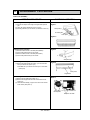
2-5 Test run
<Before test run>
● After installing, wiring, and piping the indoor and outdoor units, check for refrigerant leakage, looseness in power supply or
control wiring, and mistaken polarity.
● Use a 500-volt measure to check the resistance between the power supply terminal block and ground to make sure that it is
at least 1.0M'.
Attention:
'.
Do not use the air conditioner if resistance is less than 1.0M'
SWING
F
COOL
FAN
SPEED
MODE
AUTO
RETURN
TIMER ON/OFF CLOCK/TIMER FAN SPEED AIR DISCHARGE FILTER
AIR SWEEP
SET TEMP.
TIMER SET
CHECK
TEST RUN
REMOTE CONTROLLER
PAR-JH240KUS
<How to operate>
1. Turn ON main breaker.
2. Press TEST RUN button twice. “TEST RUN” is displayed on
remote controller.
3. Select “COOL” with MODE button to check that cool air is
beginning discharged.
Select “HEAT” with MODE button to check that warm air is
beginning discharged.(after a while)
4. Select LOW/HIGH with FAN SPEED button to check that the fan
speed changes properly.
5. Press AIR DISCHARGE button to check auto vane operation.
6. Check outdoor fan operation.
7. Check compressor operation referring to the indoor coil
temperature code displayed on the remote controller.
8. After checking, press the ON/OFF button.
TEST RUN button
Displayed during test run
·The test run works for 2 hours and stops automatically.
To cancel the test run, press ON / OFF button or TIMER ON / OFF button.
OC192-30
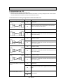
(1) Indoor coil temperature code
During the test run, the indoor coil temperature code from 1 to 15 is displayed on the remote controller instead of room
temperature. The code should fall with the lapse of time in normal COOL operation, and should rise in normal HEAT
operation.
Code
1
2
3
4
5
6
7
8
Indoor coil temperature
-40~34°F
~50°F
~59°F
~68°F
~77°F
~86°F
~95°F
~104°F
Code
9
10
11
12
13
14
15
Indoor coil temperature
~113°F
~122°F
~131°F
~140°F
~158°F
~194°F
Thermistor abnormality
(2) Trouble during test run
● If the unit malfunctions during the test run, refer to section 10 in this manual entitled “TROUBLESHOOTING.”
● When the optional program timer is connected to the conditioner, refer to its operating instructions.
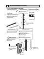
2-6 Emergency operation
When the remote controller or microprocessor malfunctions but all other parts are normal, emergency operation is started
by setting the dip switch SW3 on the indoor controller board.
<Before emergency operation>
1. Make sure the compressor and the indoor fan are operating normally.
2. Locate the defect with the self-diagnostic function. When the self-diagnostic function indicates “protective function is
working”, release the protective function before starting the emergency operation.
CAUTION: When the self-diagnostic function indicates a check code of “P5” (drain pump malfunction), DO NOT start the
emergency operation because the drain may overflow.
<How to operate>
1. For emergency cooling, set the dip switch SW3-1 to ON and SW3-2 to OFF.
SW3 setting
emergency
heating
2 .3 .4 ON
normal
operation
1 - 4 OFF
microprocessor board
2. Turn ON the outdoor unit breaker and then ON the indoor unit breaker.
Emergency operation will now start.
3. During emergency operation, the indoor fan operates on high speed, the auto vanes do not operate.
4. To stop emergency operation, turn OFF the indoor unit breaker.
5. Movements of the vanes do not work in emergency operation, therefore you have to slowly set them manually to the
appropriate position.
NOTE: The remote controller POWER ON/OFF button can not start/stop emergency operations.
CAUTION: Do not use emergency cooling for more than 10 hours, as the indoor coil may freeze.
OC192-31
3 DIP SWITCH FUNCTIONS
Each figure shows the initial setting by factory.
3-1 On remote controller board
(1) SW17(Address selector)
87654321
OFF
ON
SW17-1 ~ 6) Switch for address setting
SW17-7) When two remote controllers are used, this switch sets the controller function.
OFF : The remote controller is set as a main controller.
ON : The remote controller is set as a sub controller.
SW17-8) Switch for system back-up
This switch is not available for series PC.
(2) SW18 (Model selector)
87654321
OFF
ON
SW18-1) Switch for timer mode setting
OFF : Single day
ON : Timer every day
SW18-2) Switch for filter sign display
OFF : Filter sign absent
ON : Filter sign present
SW18-3) Switch for filter sign time setting
OFF : 100Hr
ON : 2500Hr
SW18-4) Switch for temperature unit
OFF : -C (Celsius)
ON : -F (Fahrenheit)
SW18-5) Switch for HEAT display
This switch is not available PC
SW18-6) Switch for auto vane display
OFF : Auto vane display present
ON : Auto vane display absent
SW18-7) Switch for swing display
OFF : Swing display present
ON : Swing display absent
SW18-8) Switch for louver display
OFF : Louver display present
ON : Louver display absent
3-2 On indoor controller board
(1) SW1 (Mode selector)
10 9 8 7 6 5 4 3 2 1
OFF
ON
SW1-1) Switch to change over between FAN mode and AUTOMATIC COOLING-HEATING CHANGE OVER mode
OFF : Fan mode for cooling-only models including series PC.
ON : AUTOMATIC COOLING-HEATING CHANGE OVER mode for heat pump models.
SW1-2) Switch to change over louver display
OFF : Swing
ON : Rotary
SW1-3) Switch for auto vane
OFF : Unit without auto vane
ON : Unit with auto vane
SW1-4) Switch for drain pump(Drain lift-up mechanism)
OFF : The drain pump works in only cooling mode.
ON : The drain pump works in both cooling and heating mode. (For heat pump models)
SW1-5) Switch to change the temperature to start coil frost prevention
OFF : 36_F (For previous special models)
ON : 34_F (For For all current models)
OC192-32
SW1-6) Switch for set temperature adjustment in heating mode
This is not available for series PC.
SW1-7) Switch for fan speed during thermostat OFF in heating mode
This is not available for series PC.
SW1-8) Switch for fan motor operation in heating mode
This is not available for series PC.
SW1-9) Switch for outdoor unit abnormality detection
OFF : When abnormality occurs, it is detected.
ON : Even if abnormality occurs, it is not detected.
SW1-10) Switch for AUTO RESTART FUNCTION
OFF : This function does not work.
ON : This function works.
(2) SW2 (Address selector)
654321
OFF
ON
Use SW2 to set unit-address for group control.
(3) SW3 (Emergency operation switch)
Normal operation(initial setting)
For emergency cooling
4321
OFF
ON
4321
OFF
ON
(4) SW5 (Model selector)
4321
OFF
ON
SW5-1) OFF : For models without automatic swing mechanism
ON : For models with automatic swing mechanism
SW5-2) OFF : For models with heating mode and cooling mode
ON : For models with only cooling mode including PC
SW5-3) Not yet used
SW5-4) OFF : LOSSNAY on air intake
ON : LOSSNAY air intake
(5) SW6 (Model selector)
4321
OFF
ON
SW6 is set on site for twin/triple control. This switch is not available for series PC
4 INDOOR FAN CONTROL
Indoor fan relay output.
(a) During fan ON
The indoor fan relay turns ON. One second later, the phase control will start.
(b) During fan OFF
The phase control turns OFF. One second later, the indoor fan relay will turn OFF.
OC192-33
11
TROUBLE SHOOTING
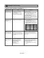
1. REMOTE CONTROLLER DISPLAY ABNORMALITY
Display abnormality
Cause
Check points
The display “centrally controlled” on remote controller does not disappear.
1) Wrong address setting of remote controller/indoor controller board.
2) Timer adapter is connected to the
remote controller.
3) Signal transmission error between
indoor unit and remote controller.
1) Check the address setting of remote controller
and indoor controller.
2) Check if the timer adapter is used correctly.
3) 1 Turn another remote controller’s DIP SW177 ON to make it sub controller.
2 Connect the sub controller to the unit, and
turn circuit breaker ON.
● If the display “centrally controlled” disappears, replace the original remote controller.
● If the display remains the same, replace the
indoor controller board.
When remote controller
POWER switch is turned
to ON, the check code
“E0”appears.
1) Signal transmission error between
indoor unit and remote controller
1) 1 Connect a sub remote controller.
2 Turn circuit breaker ON.
If the display “centrally controlled” remains,
replace the indoor controller board.
3 If the display disappears, turn the remote
controller POWER switch ON and check as
follows.
Remote controller
Sub remote controller
1 Operating Display
E0 Display
2 Operating Display
Operating Display
3 No Display
E0 Display
4 No Display
Operating Display
Malfunction
Malfunction of
Indoor Unit
Malfunction of
Remote controller
Malfunction of
Indoor Unit and
Remote Controller
Malfunction of
Remote controller
When remote controller
POWER switch is turned
to ON, operating display
appears, but disappears
soon.
1) Short circuit of indoor/outdoor connecting wire
2) Short circuit of transmission wire.
3) Wrong operation of remote controller
due to noise wave emitted by other
appliances.
1), 2) Check the wire
3) Turn the circuit breaker OFF, and then turn ON.
If the remote controller remains abnormal,
despite the above measures, replace the indoor
controller board.
Despite turning POWER
switch ON, the remote
controller display does not
appear.
1) Damaged remote controller.
2) Short circuit of transmission wire.
3) Bad contact of indoor CN40.
4) CN40 is attached to a sub unit.
5) Damaged transformer.
6) Bad contact of CN4T.
7) Broken fuse.
8) Circuit breaker OFF.
1) Measure the voltage between terminals of
remote controller. If no voltage, remove the terminals and measure the voltage between
wires. If the voltage is between 6VDC and 12V,
replace the remote controller.
2) ~ 8) Check each point.
If normal, replace the indoor controller
board.
OC192-34
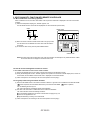
2. SELF DIAGNOSTIC FUNCTION WITH REMOTE CONTROLLER
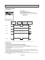
2-1 When malfunction occurs during operation
When a malfunction occurs, the indoor and outdoor units stop and the malfunction is displayed on the LCD of the remote
controller.
(1) ON the set temperature display part, “CHECK” appears, and
the unit address and the check code are displayed at one-second intervals. (Check mode)
Example
CHECK mode
CHECK
CHECK
Check
code
Unit
address
(2) When one remote controller controls several units in the group control,
the LCD shows the unit address and check code of the first malfunctioning unit.
(3) To cancel the check mode, press the power ON/OFF button.
MODE
TIMER ON/OFF CLOCK/TIMER FAN SPEED AIR DISCHARGE FILTER
AIR SWEEP
SET TEMP.
TIMER SET
CHECK
TEST RUN
REMOTE CONTROLLER
PAR-JH241KUS
CHECK button
NOTE: The latest check code is memorized, even if the check mode is cancelled by the way mentioned above. It takes
60 seconds maximum to display the memorized check code.
2-2 How to use the self diagnostic function for service
A. For normal control with one unit and one remote controller
(1) Pressing the CHECK button on the remote controller twice starts the self diagnostic function.
(2) During the self diagnostic function, “CHECK” appears at two positions on the remote controller display. Then, at least 10
seconds later, the unit address and the check code is displayed at one-second intervals.
(3) Check and repair the unit according to the check code. (Refer to the next page.)
2-3 For group control using one remote controller
(1) Press the SET TEMP. button on the remote controller to advance or go back to the unit address. Each time SET TEMP.
button is pressed, the unit address advances by one. Each time SET TEMP.
button is pressed,
the unit address goes back by one.
The check code and the unit address, appear will be displayed.
(2) The check code “U8” means no malfunction has occurred since installation.
The check code “EO” means the following conditions:
● The unit address displayed on the remote controller does not apply to any unit.
● power is not supplied to the unit.
● Signal transmitting / receiving circuit is abnormal.
(3) Check and repair the unit according to the check code. (Refer to the next page.)
OC192-35
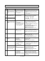
Check
Diagnosis of malfunction
Cause
Check points
code
Signal transmitting/receiving During individual unit control
1) Check the transmission wire.
E0
error
1) Bad contact of transmission
2) Check with another remote controller. If “E0” is
Indoor controller does not
wire
still indicated, replace the indoor controller
respond to remote controller 2) Signal transmitting/receiving cirboard.
signal.
cuit is abnormal.
If other check code appears. replace the former
remote controller.
P1
Abnormality of room temper- 1) Bad contact of thermistor
2) Damaged thermistor
ature thermistor (TH1 or
RT1)
P2
Abnormality of pipe temperature thermistor (TH2 or RT2)
P3
Signal transmission error
(Remote controller does not
respond to indoor controller
signal.)
1) Check the transmission wire.
1) Bad contact of transmission
2) Check with another remote controller.
wire
If “P3” is still indicated, replace the indoor
2) Signal transmitting/receiving cirboard.
cuit is abnormal.
If other check code appears, replace the origi3) Wrong operation of remote connal remote controller.
troller due to infrared signal
3) Short-circuit between 1 and 2 of CN40 and
from other appliances
attach CN40 to the following units.
● Second unit in twin control
● Second and third units in triple control
● Sub units in group control
P4
Abnormality of drain sensor
1) Bad contact of transmission
wire
2) Damaged thermistor
1) Check the connector.
2) Measure the resistance of the thermistor 4 - 5.
As for the normal resistance, refer to the case
P1.
If normal, replace the indoor controller board.
P5
Malfunction of drain pump
1) Malfunction of drain pump
2) Damaged drain sensor
1) Check the drain pump.
2) ● Check the drain sensor.
● Check the drain sensor heater. If normal, its
resistance should be 82'.
If normal, replace the indoor controller board.
P6
Coil frost protection has
worked.
1)
2)
3)
4)
1)
2)
3)
4)
P7
System error
1) Wrong address-setting
1)
2) Signal transmitting/receiving cir- 2)
cuit of remote controller is
abnormal.
3) Wrong SW6-setting
3)
Short cycle of air cycle
Dirty air filter
Damaged fan
Abnormal refrigerant
1) Check the thermistor.
2) Measure the resistance of the thermistor.
If normal, it should be as follows.
32-F····15k'
86-F ··4.3k'
50-F····9.6k'
104-F ··3.0k'
68-F····6.3k'
If is normal, replace the indoor controller board.
Clear the obstructions from the air cycle.
Clean the air filter
Check the fan.
Check the refrigerant temperature.
Check the address-setting.
Check with another remote controller. If check
code other than “P7” appears, replace the original remote controller.
Check SW6 setting.
Signal transmission error
1) Bad contact of transmission
1) Check the transmission wire.
In twin/triple control, the first
wire
2) Short-circuit between 1 and 2 of CN40 and
unit has not received signal 2) Wrong operation due to infrared
attach CN40 to the following unit.
from the second unit or the
signal from other appliances
● Second unit in twin control
third unit for 5 minutes.
● Second and third units in triple control
● Sub units in group control
P8
Abnormality in outdoor unit
1) Wrong wiring of indoor/outdoor
connecting wire
2) Reversed phase
3) Protection device has worked
4) Damaged outdoor coil thermistor
OC192-36
1)
2)
3)
4)
Check the indoor/outdoor connecting wire.
Change the connection of electric wiring.
Check the detail of the protection device.
Measure the resistance of the pipe temperature
thermistor. If normal, replace the outdoor controller board.
3. WRONG WIRING ON SITE
3-1 Between remote controller and indoor unit
If the wire is disconnected between the remote controller and the indoor unit, nothing is displayed on the remote controller
when the POWER button is pressed. The beep sound will also not be heard.
3-2 Phenomenon due to wrong wiring between indoor and outdoor units
Wrong wiring
Thermostat
Indoor
Phenomenon
OFF
Operation stops.
ON
4-Way valve is turned to ON. 9 minutes later, the check code “P8”
appears on the remote controller display.
OFF
The outdoor unit stops.
ON
Operation stops. 9 minutes later, the check code “P8” appears on the
remote controller display.
OFF
The outdoor unit stops.
ON
Operation stops. 9 minutes later, the check code “P8” appears on the
remote controller display.
OFF
The outdoor unit stops.
ON
Operation stops. 9 minutes later, the check code “P8” appears on the
remote controller display.
OFF
The outdoor unit stops.
ON
Operation stops. 9 minutes later, the check code “P8” appears on the
remote controller display.
OFF
Operation stops.
ON
9 minutes later, the check code “P8” appears on the remote controller
display.
Outdoor
1
1
2
2
3
3
Indoor
Outdoor
1
1
2
2
3
3
Indoor
Outdoor
1
1
2
2
3
3
Indoor
Outdoor
1
1
2
2
3
3
Indoor
Outdoor
1
1
2
2
3
3
Disconnection between 1 and 1 or 2
and 2.
Disconnection between 3 and 3.
OFF
Normal operation.
ON
OC192-37
4. OTHER TROUBLES AND CAUSES
vanes do not work.
t
Unit stops after 5 to
20 seconds operation
Air discharge display
is OFF and air discharge UP/DOWN
button is not available.
Vane motor does not work.
Limit switch does not work.
Connector is badly connected.
Vane motor is badly assembled.
Indoor controller board is damaged.
t
Protection function has broken
t
In this case, remote
controller is normal.
Indoor unit is regarded
as without auto vane.
t
Horizontal angle has
not been detected.
t
t
t
Vane motor has broken.
Vane motor relay has broken.
Limit switch has broken.
Size of cam is not proper.
Refer to check code on remote controller display.
See page OC192-36.
Indoor controller has
broken.
Dip switch setting is
wrong.
Indoor controller has
broken.
Vane motor has broken.
Vane motor limit switch
is badly connected.
Auto vane is wired after
power is turned to ON.
Power ON/OFF switch
is not available.
t
Beep sound is heard,
but display is turned to
OFF.
Beep sound is not
heard, and display
remains OFF.
t
Indoor/outdoor connecting wire is wrong connected.
Indoor/outdoor connecting wire shorts.
Compressor protector
has broken.
Deicer has broken.
t
Remote controller has
broken.
Transmission wire is
badly connected.
“Centrally controlled” is displayed.
OC192-38
t
Vane motor limit switch
has broken.
Vane motor is broken.
t
Badly connect
Disconnected
t
Transmission wire has
broken.
Connector is badly connected.
Indoor terminal block is
badly connected.
Remote controller terminal block is badly
connected.
5. How to check the parts
Parts name
Check points
Room temperature
thermistor
(TH1)
Disconnect the connector then measure the resistance using a tester.
(Surrounding temperature 50-F~86-F)
Liquid pipe
thermistor
(TH2)
Vane motor
Normal
Abnormal
4.3k"~9.6k"
Open or short
(Refer to the thermistor)
Measure the resistance between the terminals using a tester.
(Surrounding temperature 68-F~86-F)
White 4
Normal
M
Connector
Orange 2
Red 1
24EK1
30EK1
36,42EK1
186~214"
140~160"
140~160"
Abnormal
Red — Yellow
5
3
Blue
Yellow
Red — Blue
Red — Orange
Open or short
Red — White
Fan motor
Measure the resistance between the terminals using a tester.
Relay connector
1
Red
2 White
3 Black
1
2
3
Normal
Motor terminal
or
Relay connector
PC
24EK1
30EK1
36,42EK1
Red-Black
45.0"
45.0"
20.4"
White-Black
44.8"
44.8"
20.7"
Abnormal
Open or short
Protector
<Thermistor Characteristic graph>
Thermistor for
lower temperature
< Thermistor for lower temperature >
Room temperature thermistor(TH1)
Liquid pipe thermistor(TH2)
50
Thermistor R0=15k' ± 3%
Fixed number of B=3480k' ± 2%
Rt=15exp { 3480(
32°F
50°F
68°F
77°F
86°F
104°F
1
273+{(t-32)/1.8}
1 )}
273
15k'
9.6k'
6.3k'
5.2k'
4.3k'
3.0k'
Resistance (K")
40
30
20
10
0
OC192-39
-4
14
32 50 68 86
Temperature (-F)
104 122
12
SYSTEM CONTROL
1. VARIETY OF SYSTEM CONTROL FUNCTIONS
1 Group control by a
single remote controller
(See page
OC192-41.)
Unit
Unit
A number of units, installed at different locations can be
started and controlled with a single remote controller. The
remote controller can be mounted in a different location
using a non-polar two-wire cable, which can be extended
up to 550 yards. A maximum of 50 units are controllable
by a single remote controller. All units operate in the
same mode.
Unit
Remote
controller
2 Control using two
remote controllers
(See page
OC192-42.)
Unit
Unit
Two remote controllers can be used to control either one
unit or several units in group control. This enables to control units with ease either from a distance or close rang.
Units operate according to the latest command from either
remote controller.
Unit
Remote
controller
3 Both remote ON/
OFF and individual controls
(See page
OC192-42.)
Optional
adapter
Relay box
Unit
Remote ON/OFF
switch
4 Individual control
by grouping
remote controllers
(See pageOC19243.)
Remote
controller
Unit
Unit
Unit
All units can be turned on or off simultaneously using the
remote ON-OFF switch. Besides each unit can be controlled individually by each remote controller. During
remote ON-OFF control, a message of “CENTRALLY
CONTROLLED” is displayed on the LCD of the remote
controller.
This method is available for both one unit control and several units control.
By grouping the controllers to one place, several units
installed at different locations can be controlled individually, and operation conditions of all units are visible without
a special control board. Control method is the same as
that of the single unit with a single remote controller.
Remote
controller
5 Multiple remote
control display
(See page
OC192-44.)
Unit
Remote control
display board
6 AUTO RESTART
FUNCTION
(See page
OC192-44.)
Unit
Unit
Several units can be controlled by remote control display
board. Operation conditions of all the units are visible with
the remote control display board.
Individual control by each remote controller is also available.
Remote
controller
Circuit breaker
Remote
controller
Units can be started or stopped by circuit breaker on or
off.
Remote controller is also available.
By this function, when the power is restored after power
failure, the unit restarts automatically.
OC192-40
2. GROUP CONTROL BY A SINGLE REMOTE CONTROLLER
A maximum of 50 units can be started in order according to the dip switch settings
2-1 How to wire
Figure 1
To remote
controller
To the next unit
To the next
unit
L1 L2GR 1 2 3
Master unit
electrical box
L1 L2GR 1 2 3
(1) Connect the remote controller to the double terminal block
on the indoor controller board of the master unit, that is,
No.0 unit. (See Figure 1.)
(2) Connect the double terminal block of the master unit to the
double terminal block of No.1 unit.
(3) Connect the double terminal block of No.1 unit to the double terminal block of No.2 unit.
(4) Continue the process until all the units are connected with
two-wire cables. (See Figure 2.)
(5) Remove the connector CN40 from the indoor controller
board of each unit except the master unit. (See Figure 3.)
(6) Set the unit-address of each unit with SW2 on the indoor
controller board following the instructions below.
Next unit
electrical box
The last unit
dose not have
this wire.
Figure 2
2-2 How to set unit-address
Master
unit
The unit-address also serves as a successive-start timer which
starts each unit at intervals of 1 second. If two or more units
have the same unit-address in a group control, operation stops
due to system error. Be sure to set SW2 correctly following the
instructions below.
(1) Each lever of SW2 shows the number as follows.
SW2-1 : 1
SW2-4 : 8
SW2-2 : 2
SW2-5 : 16
SW2-3 : 4
SW2-6 : 32
(2) Total number of levers turned to ON shows the address of
the unit.
If you turn ON SW2-1 and SW2-2, the unit-address is set
as No.3.
(3) In this way, set from the. master unit to the last unit.
Do not forget to set the master (No. 0) unit.
No.1 unit
No.2 unit
Last unit
2-wire cable
Figure 3
Indoor controller board ▼
SW2
CN40
Disconnect CN40
(Except master unit)
Setting examples
Master (No. 0) unit
No. 1 unit
No. 2 unit
No. 4 unit
No. 8 unit
No. 16 unit
No. 32 unit
ALL OFF
1 ON
2 ON
3 ON
4 ON
5 ON
6 ON
SW2
1
Unit address & start
delay in seconds.
2
3
4
5
6
1
0
2
3
4
5
6
1
1
2
3
4
5
6
1
2
2
3
4
5
6
1
4
2
3
4
5
6
1
8
2
3
4
5
6
1
16
2
3
4
32
2-3 Unit control
The remote controller can control all units ON/OFF, temperature,air flow, and swing louver. However, the thermostat in
each unit turns to ON or OFF individually to adjust the room temperature.
OC192-41
5
6
3. CONTROL USING TWO REMOTE CONTROLLERS
Two remote controllers are available for control of either one unit or a group of units. Units operate according to the latest command from either of the two remote controllers.
However, before operation, be sure to set one remote controller for "main controller" and the other for "sub controller", using
dip switch SW17-7 of the remote controller.
Individual
operation
Multiple operation
Remote
controller
Remote
controller
Remote
controller
Remote
controller
3-1 How to set SW17-7
Remote controller
(1) For the main remote controller, turn SW17-7 OFF. (See Figure 5.)
(2) For the sub remote controller, turn SW17-7 ON.
Figure 5
3-2 Remote controller LCD indication
(1) The same indication always appear on both the main and sub remote controllers, excepting the timer operations.
(2) Timer operation can be set with either of the two remote controllers. However,
LCD indication appears only on the remote controller used for timer settings.
(3) If both remote controllers are set for timer operation with different time-settings, the timer operation of shorter remaining-time is effective.
(4) Self-diagnostic function is available with either of the two remote controllers.
If one of the remote controllers is used for the self-diagnostic function, the
other remote controllers displays the check mode.
If the self-diagnostic function is reset by either of the two remote controllers,
both remote controllers are reset.
Main remote controller
0
9
8
7
6
Sub remote controller
5
4
3
2
1
0
9
8
7
6
5
4
3
2
1
Turn SW17-7 ON
4. REMOTE ON-OFF AND INDIVIDUAL REMOTE CONTROLS
This method is available to control one unit or any number of units.
The following operations are available by connecting a relay, a timer adapter(PAC-715AD), and remote ON/OFF switch to the
system. Timer adapter, (PAC-715AD), is an optional part. Other parts are on the market.
(A) To start all units in order by remote ON-OFF switch
(B) To stop all units simultaneously by remote ON-OFF switch
(C) To switch from the remote ON-OFF control to the individual remote control
4-1 System
Figure 6 shows the case of three units as an example. The same is the case with any number of units.
Figure 6
Timer adapter PAC-715AD
Power supply of
control circuit
Remote
ON/OFF
switch
Relay box
2-wire
remote
Timer adapter cables
controller
cable
Remote
controller
OC192-42
NOTE1 : Install the relay box where you can be serviced easily.
NOTE2 : For control circuit wiring, use a wire of No. 14 AWG or a control cable according to the power supply of control
circuit.
NOTE3 : When the power supply of the control circuit is 115/230V AC,
● Do not connect the control circuit wire to the remote controller cable directly.
● Do not place the control circuit wire and the remote controller cable into the same conduit tube.
4-2 Basic wiring
Caution : Before starting all units simultaneously by the remote ON-OFF switch, be sure to connect a sequence-start timer
into the remote ON-OFF circuit. Otherwise, rush of starting current exert a bad influence upon the power supply.
Remote
ON/OFF
switch
Power
supply
No.1 unit
relay box
No.2 unit
relay box
SW1
Next unit
SW2
Glow switch or pilot lamp can be
combined to easily identify the
on-off mode of SW1 and SW2.
T
T
X2
X2
T
To
No.1
unit
X2
To
No.2
unit
T
X2
Remote controller
Timer adapter cables
4-3 Switch function of remote ON-OFF switch
SW1
(Switches between
remote ON and OFF.)
ON
(Start)
OFF
(Stop)
SW2
(Switches between remote ON-OFF and individual control)
ON
OFF
(Remote ON-OFF control)
(Individual control)
All units start together.
w1
Each unit can be controlled by each
Individual control is not available.
remote controller.
All units stop together.
w2
Remote ON-OFF switch is not available.
Individual control is not available.
w1 After all units start together, if SW2 is turned OFF, each unit can be individually stopped by each remote controller.
w2 After all units stop together, if SW2 is turned OFF, each unit can be individually started by each remote controller.
5. INDIVIDUAL CONTROL BY GROUPING THE REMOTE CONTROLLERS
● Grouping the remote controllers allows individual control and centralized monitoring of units installed in different places without a
special control board.
● Remote control cables can be extended up to 550 yards. When the
cable length exceeds 39 ft, use the double-insulated two-core cable
such as Belden 9407, and the cable thickness must be No. 22
AWG or above.
● When gathering the power ON/OFF switches of air conditioners
near the remote controllers, you should also install the power
ON/OFF switch near each unit to prevent electric trouble in servicing.
OC192-43
Remote
controller cable (2-core)
Remote controller
6. MULTIPLE REMOTE CONTROL DISPLAY
You can control several units by a multiple remote control display, if you
wire an optional multiple display adapter (PAC-725AD) with relays and
lamps on the market.
Indoor controller board
6-1 How to wire
(1) Connect the multiple display adapter to the connector CN51 on the
indoor controller board.
(2) Wire three of the five wires from the multiple display adapter as shown
in the below figure.
<Wiring >
RL
X1
GREEN
5
CN51
X1
YELLOW
X2
ORANGE
RED
Electrical insulation is needed.
BROWN
1
connector(5P)
Optional multiple display
adapter
X2
GL
Power
supply
CN51
Wiring at the actual place
The maximum distance between
indoor board and relay is 33 feet.
[Notes on Signs]
X1:Relay (for check lamp)
X2:Relay (for operation lamp)
RL:Check Lamp
GL:Operation Lamp
[Field supplied parts]
Relays:DC 12V with rated coil power consumption below 0.9W.
Lamps:Matching to power supply voltage.
<System>
Power
supply
3wires
3wires
3wires
2wires
No.1 unit
No.2 unit
Remote
controller
cable
Multiple remote control
Remote
ON-OFF display
controller
(Field supply)
No.3 unit
Relay box
(Field supply)
Remote
controller
Remote
controller
(Operation check)
<Wiring diagram>
Power
supply
RL-1
X1-1
GL-1
X2-1
RL-2
X1-2
GL-2
X2-2
X1
X2
X1
1
Multiple remote controller adapter
5
No.1 unit
1
No.2 unit
X2
RL-3
X1-3
GL-3
X2-3
X1
X2
5
1
5
No.3 unit
connect to
the connector CN51
Relay box
Multiple Remote Control Display
7. AUTO RESTART FUNCTION
Unit can be started or stopped by power supply ON or OFF.
Therefore, after power failure, when the power is restored, the unit restarts automatically.
To enable this function, turn ON the dip switch SW1-10 on the indoor controller board.
For remote control, connect the optional timer adapter (PAC-715AD).
<Wiring>
A
A
B
B
Brown
Red Orange Remote
controller
A : an optional timer adapter
B : a single-throw switch
Brown
Red Orange Remote
controller
OC192-44
13
DISASSEMBLY PROCEDURE
Indoor unit (PC24EK1)
OPERATING PROCEDURE
1. Removing the air intake grille
(1) Unhook the clasps at the edge of the grille and open the
grill.
(2) Lift up the grill in direction of arrow 1 in Fig.2.
(3) Pull the grill toward you to remove. (In direction of arrow 2)
PHOTOS&ILLUSTRATION
Figure 1
Side panel (L)
Air intake grille
Lower panel
Figure 2
2
1
2
1
2. Removing the side panel
(1) Remove a white screw of the side panel (RIGHT).
(2) Pull out the panel toward you to remove.
(3) Remove a white screw of the side panel (LEFT).
(4) Pull out the panel toward you to remove.
Figure 3
Side panel (R)
3. Removing the lower panel
(1) Remove the lower panel set screws, 2 pcs on each side
and 3 pcs at the rear. (total 7 pcs)
W PC24EK has 4 pcs at the rear and 2 pcs on each side.
(total 8 pcs)
Figure 4
Lower panel
Support bar
4. Removing the electrical box
(1) Remove the air intake grille. (Refer to 1.)
(2) Remove the support bar set screw and remove the bar.
(See fig. 4)
(3) Loose the lead clamps (2 pcs) for the sirocco fan and the
louver motor. (See photo 1)
Photo 1
Electrical box
Clamps for fan lead
OC192-45
OPERATING PROCEDURE
PHOTOS&ILLUSTRATION
(4) Remove the electrical box set screws. (2 pcs) Pull down the
electrical box and hang it from the rear panel using the S
hooks located on the both sides of the box.
(5) The electrical box has two covers. (R and L)
Remove the 2 screws on the cover (R), and remove the
screw on the cover (L). Then remove the box covers.
(6) Now you can check the inside of the electrical box.
(See fig. 6)
Figure 5
Electrical box
Set screws (2 pcs)
Box cover set screws (3 pcs)
Figure 6
Fan lead wire
Transformer
Louver motor
lead wire
Connector for
fan lead
Fuse
Terminal block
(Power)
Terminal block
(Control)
Terminal block
(Remote controller)
Capacitor
OC192-46
OPERATING PROCEDURE
5. Removing the drain pan
After removing the lower panel:
(1) Remove the drain pan support set screws (2 pcs)
(2) Remove the louver support set screw. (See photo 2)
(3) Remove the drain pan.
PHOTOS
Photo 2
Set screws
Drain pan
6. Removing the front panel assembly
After removing the drain pan:
(1) Pull the lower louver toward you and unhook the clasps. (2
points at the center)
(2) Remove the front panel white set screws. (4 pcs)
(3) Remove the side box set screws on the both sides.
(4 screws on the side and front, 1 screw at the bottom, on
each side.)
(4) The panel assembly will be removed.
(See photo 3)
Photo 3
Front panel assy
Front panel white set screws
Side box set screw
7. Removing the louver motor
Remove only the right side panel to remove this motors.
(1) Remove setting screws of motor. (2 pcs) (See photo 5)
Photo 4
Side box (R)
Louver motor
8. Removing of the swing louver
(1) Remove the swing louver from the joint on the right side.
(2) Slide the louver out to the left side.
Side box (L)
Front louver
OC192-47
Support bar
OPERATING PROCEDURE
PHOTOS
9. Removing the front louver
(1) Pull and unhook the louver toward you. (Clasps are 5 pcs)
Photo 5
Thrmistor check plate
Louver motor
set screw
Front panel
Side plate (S)
lower
Thrmistor
Side box
Right
Photo 6
Swing louver
Side box
left
OC192-48
Front panel
lower
OPERATING PROCEDURE
10. Removing the fan motor
After remove the electrical box covers:
(1) Disconnect the lead connector for fan.
(2) Pull out the room temp. thermistor from the casing (A).
(See photo 7)
(3) Loose the shaft joint set screws (2 pcs) with a hexagonal
wrench. (size 3mm).
(4) Unhook the casing (A) by pushing. (2 points for each side)
(5) Open about half of the casing (A) and take it out.
(6) Loose the fixing band set screws. (1 pcs on the both sides
of the fan motor.)
(7) Remove the fixing bands.
(8) Take out the fan motor.
PHOTOS
Photo 7
Fan motor
Fixing bands
Casing (A)
Room temp. thermistor
Casing clamps
Photo 8
Sirocco fan (A)
Fixing bands
11. Removing the room temperature thermistor
After removed the electrical box covers:
(1) Pull out the room temperature thermistor from the casing
(A).
(2) Disconnect the connector (CN-20) from the controller
board in the electrical box.
(3) Take out the thermistor.
12. Removing the indoor coil thermistor
After removed the electrical box covers:
(1) Remove the right side panel.
(2) Remove the set screw of the thermistor check plate and
the set screws of the side plate. (3 pcs)
(See photo 5)
(3) Remove the indoor coil thermistor from the heat exchanger.
(4) Disconnect the connector (CN-21) from the controller
board in the electrical box.
(5) Take out the thermistor.
OC192-49
Photo 9
Set screws (7 pcs)
Electrical box
Set screws
Lower panel
14
PARTS LIST
PC24EK PC30EK STRUCTURAL PARTS
PC24EK1 PC30EK1
9
3
5
1
22
6
2
8
5
4
12
13
11
14
7
18
19
15
17
16
OC192-50
20
10
7
Part number that is circled is not shown in the figure.
No.
Parts No.
Parts Name
1 R01 055 662 SIDE PANEL (LEFT)
Specifications
Drawing No.
Q'ty/set
Price
Circuit Recom-
PC
Remarks Diagrammended 24
30
Unit Amount
Symbol Q'ty
EK EK1 EK EK1
1 1 1 1
2 R01 055 661 SIDE PANEL (RIGHT)
1
1
1
1
3 T7W 052 676 REAR & TOP PLATE
1
1
1
1
4 R01 051 651 FRONT PANEL
1
1
1
1
5 R01 A25 500 AIR FILTER
4
4
4
4
6 R01 055 501 AIR FILTER (SUB)
1
1
1
1
7 R01 029 691 INTAKE GRILL
2
2
2
2
8 R01 029 061 HINGE
4
4
4
4
9 T7W 051 501 AIR FILTER
1
1
1
1
10 R01 029 054 CATCH
4
4
4
4
11 R01 146 669 LOWER PANEL
1
1
1
1
12 T7W 052 001 FRONT GRILL
1
1
1
1
13 R01 045 048 LOUVER SUPPORT
1
1
1
1
14 R01 045 003 SWING LOUVER
1
1
1
1
15 R01 029 086 FRONT LOUVER (LEFT)
1
1
1
1
16 R01 029 085 FRONT LOUVER (RIGHT)
1
1
1
1
17 R01 045 087 FRONT LOUVER (CENTER)
1
1
1
1
18 T7W 056 068 SIDE BOX (LEFT)
1
1
1
1
19 T7W 056 067 SIDE BOX (RIGHT)
1
1
1
1
20 T7W 146 222 LOUVER MOTOR
1
1
1
1
21 R01 045 808 LEG
22 R01 82E 656 FILTER GUIDE
2
2
2
2
1
1
1
1
OC192-51
ML
PC36EK PC42EK STRUCTURAL PARTS
PC36EK1 PC42EK1
4
10
3
6
23
5
1
2
9
13
14
5
15
16
19
18
20
17
21 7
12
OC192-52
11
8
Part number that is circled is not shown in the figure.
No.
Parts No.
Parts Name
1 R01 055 662 SIDE PANEL (LEFT)
Specifications
Drawing No.
Q'ty/set
Price
Circuit Recom-
PC
Diagram
mended
Remarks
36
42
Unit Amount
Symbol Q'ty
EK EK1 EK EK1
1 1 1 1
2 R01 055 661 SIDE PANEL (RIGHT)
1
1
1
1
3 T7W 056 676 REAR & TOP PLATE
1
1
1
1
4 R01 055 651 FRONT PANEL
1
1
1
1
5 R01 A25 500 AIR FILTER
5
5
5
5
6 R01 055 501 AIR FILTER (SUB)
1
1
1
1
7 R01 029 691 INTAKE GRILL
2
2
2
2
8 R01 029 692 INTAKE GRILL
1
1
1
1
9 R01 029 061 HINGE
6
6
6
6
10 T7W 051 501 AIR FILTER
1
1
1
1
11 R01 029 054 CATCH
5
5
5
5
12 R01 147 669 LOWER PANEL
1
1
1
1
13 R01 147 001 FRONT GRILL
1
1
1
1
14 R01 045 048 LOUVER SUPPORT
1
1
1
1
15 R01 055 003 SWING LOUVER
1
1
1
1
16 R01 029 086 FRONT LOUVER (LEFT)
1
1
1
1
17 R01 029 085 FRONT LOUVER (RIGHT)
1
1
1
1
18 R01 055 087 FRONT LOUVER (CENTER)
1
1
1
1
19 T7W 056 068 SIDE BOX (LEFT)
1
1
1
1
20 T7W 056 067 SIDE BOX (RIGHT)
1
1
1
1
21 T7W 146 222 LOUVER MOTOR
1
1
1
1
22 R01 045 808 LEG
2
2
2
2
23 R01 82E 656 FILTER GUIDE
1
1
1
1
OC192-53
ML
PC24EK PC30EK PC36EK PC42EK ELECTRICAL PARTS
PC24EK1 PC30EK1 PC36EK1 PC42EK1
4
6
3
5
2
9
1
11
8
7
10
12
13
Q'ty/set
Price
Circuit Recom-
PC
Remarks
Specifications
Diagrammended No.
Parts No.
Parts Name
Drawing No. 24 30 36 42
Unit Amount
Symbol Q'ty
EKEK1 EKEK1 EKEK1 EKEK1
R01 K01 310 INDOOR CONTROLLER BOARD I.B
1 1 1 1 1
1
T7W E06 310 INDOOR CONTROLLER BOARD I.B
1 1 1 3 T7W 829 070 CONTROLLER CASE
4 T7W 046 260 TRANSFORMER
RED:15.5VAC, 0.3A
BRN:11.0VAC,
0.6A
1 1 1 1 1 1 1 1 1 1 1 1 1 1 1 1 1 1 1 1 1 1 1 1 5 T7W 410 716 TERMINAL BLOCK
2 T7W 410 239 FUSE
250V 6A
F
T
2P (L1,L2)
1 1 1 1 1 1 1 1 R01 556 246 TERMINAL BLOCK
2P (1,2)
2
TB2,3
T7W E02 716 TERMINAL BLOCK
2P (1,2)
2 2 2 2 1 1 1 1 1 1 1 1 TB2,3
7 T7W 046 255 FAN MOTOR CAPACITOR 12= 220V
8 T7W 450 200 REMOTE CONTROLLER BOARD 1
1
1
1
9 T7W E01 713 REMOTE CONTROLLER BOARD 1
1
1
10 T7W 351 077 REMOTE CONTROLLER COVER 1
1
1
1
11 T7W E03 049 REMOTE CONTROLLER COVER 1
1
1
1
1
1
1
1
1
1
1
6
12 R01 L72 095 SCREW CAP
13
T7W 556 305 REMOTE CONTROLLER CABLE 39ft
T7W A00 305 REMOTE CONTROLLER CABLE 33ft
1
1
2
2
1
OC192-54
1
2
1 PAR-JC250KUS
1
TB1
C
R.B
R.B
PC24EK PC30EK FAN SECTION PARTS
PC24EK1 PC30EK1
13
5
4
3
2
12 1
2
8
7
6
9
10
11
No.
Parts No.
Parts Name
1 T7W 052 762 FAN MOTOR
Specifications
Drawing No.
RB09CC
Q'ty/set
Price
Circuit Recom-
PC
Remarks Diagrammended 24
30
Unit Amount
Symbol Q'ty
EK EK1 EK EK1
1 1 1 1
MF
2 R01 811 105 RUBBER MOUNT
2
2
2
2
R01 700 116 JOINT (SHAFT)
1
1
R01 29J 116 JOINT (SHAFT)
1
1
3
4
R01 G12 100 FAN SHAFT
1
1
1
1
5 R01 621 103 SLEEVE BEARING
1
1
1
1
R01 G18 114 SIROCCO FAN
3
3
T7W E00 114 SIROCCO FAN 3
3
6
7
R01 055 110 CASING SET
3
3
T7W E02 110 CASING SET
3
3
R01 J21 202 ROOM TEMPERATURE THERMISTOR
1
1
RT1
T7W E17 202 ROOM TEMPERATURE THERMISTOR
1
1
TH1
9 R01 J07 202 PIPE TEMPERATURE THERMISTOR
1
1
1
1
RT2,TH2
T7W 450 480 HEAT EXCHANGER
1
1
T7W 451 480 HEAT EXCHANGER
8
10
1
1
11 T7W 048 529 DRAIN PAN
1
1
1
1
12 R01 83E 126 PIECE (MOTOR)
1
1
1
1
13 R01 G24 145 BEARING SUPPORT
1
1
1
1
OC192-55
PC36EK PC42EK FAN SECTION PARTS
PC36EK1 PC42EK1
3 2 13 1
4
2 3
4
5
14
5
8
14
8
7
9
11
10
7
12
No.
Parts No.
1 T7W 056
2 R01 560
R01 700
3
R01 29J
4 R01 G24
5 R01 705
R01 G18
6
T7W E00
R01 G24
7
T7W E01
R01 055
8
T7W E02
R01 J21
9
T7W E17
10 R01 J07
R01 J74
11
T7W E28
12 T7W 050
13 R01 830
14 R01 G24
762
105
116
116
100
103
114
114
114
114
110
110
202
202
202
480
480
529
126
145
Parts Name
6
7
Specifications
Drawing No.
FAN MOTOR
KRB 152CA
RUBBER MOUNT
JOINT (SHAFT)
JOINT (SHAFT)
SHAFT
SLEEVE BEARING
SIROCCO FAN
SIROCCO FAN SIROCCO FAN
SIROCCO FAN
CASING SET
CASING SET
ROOM TEMPERATURE THERMISTOR
ROOM TEMPERATURE THERMISTOR
PIPE TEMPERATURE THERMISTOR
HEAT EXCHANGER
HEAT EXCHANGER
DRAIN PAN
PIECE (MOTOR)
BEARING SUPPORT
Q'ty/set
Price
Circuit Recom-
PC
Remarks Diagrammended 36
42
Unit Amount
Symbol Q'ty
EK EK1 EK EK1
MF
1 1 1 1
2 2 2 2
2
2
2
2
2 2 2 2
2 2 2 2
2
2
2
2
2
2
2
2
4
4
4
4
RT1
1
1
TH1
1
1
1 1 1 1
RT2,TH2
1
1
1
1
1 1 1 1
1 1 1 1
2
2
2
2
OC192-56
15
OPTIONAL PARTS
1. TIMER
When using a program timer, a program timer adapter (PAC-825AD) is also needed.
(PAC-825AD is included with PAC-SC32PTA.)
Part No.
Model Name
PAC-SC32PTA (with set back function)
Program timer
1-1 Program timer specifications
Parts name
Parts No.
Exterior dimensions (inch)
Installation
Type of clock
Clock accuracy
Display-Time
-Week
-Timer setting unit
Program cycle
Timer setting unit
No. of set points
Power rating
Program timer
PAC-SC32PTA
5-4/32x4-23/32x23/32 (130x120x18mm)
Wall mount
Quartz
±50 second / month at 77°F
Liquid crystal display
Liquid crystal display
Liquid crystal display
24 hours
30 minutes
48 / day
5V DC ±5% (Supplied by Remote Controller)
1-2 Feature of program timer
(1) Daily timer function
Daily timer can be set in 30 minutes units for up to 24 hours.
Each unit can be set for unit ON, unit OFF, or setback operation.
(2) Setback operation (PAC-SC32PTA)
Set back operation is useful for reducing running costs
e.g. At a hotel with a 24-hour system
8:00~23:00 Cooling operation with set temperature at 79°F
23:00~8:00 Setback operation with 4 degrees of setback
As shown in the chart on the right, the set temperature rises 4 degrees
automatically during the setback operation. When the setback operation
ends, normal operation will begin.
(3) Weekly timer function
Daily timer function can apply to each day of the week.
83°F
79°F
8:00
Normal
operation
23:00
Setback
operation
8:00
Normal
operation
1-3 How to connect program timer
(1) Install the program timer next to the remote controller the same way as the remote controller is installed.
(2) Connect the program timer and the remote controller with a 5-wire cable as shown in the figure below
Connect to indoor unit
NOTE:While the program timer is connected to the remote controller, the
24hour ON/OFF timer on the remote controller will not operate.
2-wire cable
SET
FILTER
SET
MONITOR
BACK
S M T W T F S
0
3
6
12
12
15
18
21
15
CHECK MODE
24
TEST RUN
SET/MONITOR
TODAY
WEEKLY
SETTING
SET BACK
ON
CLOCK
OFF
ON
DAILY
SETTING
SET BACK
DAILY TIMER
OFF
PROGRAM TIMER
PAC-SC32PTA
4
Use 5-wire cable
Connect to CN1
Connect to CN1
OC192-57
1-4 Names and functions
<PAC-SC32PTA>
WEEKLY TIMER SETTING DISPLAY
CURRENT TIME DISPLAY
SET BACK DISPLAY
DAILY TIMER SETTING DISPLAY
Sets timer for a week.
During MONITOR status,current
time is display.
During Daily timer setting, a
time desire for timer setting is
displayed.
Indicates the set back range.
24 hours is divided into 48 blocks and each
block express 30 minutes.
The block display consists of 3 pattern.
Set back
1=2°F 2=4°F 4=8°F 6=12°F 8=16°F
SET BACK SETTING SW
SET
SET/MONITOR DISPLAY
When SET is displayed, clock adjustment,
change of weekly day, daily and weekly timer
setting can be performed.
During MONITOR is display, all switches
except SET/MONITOR SW are invalidated.
This is normal status.
SET
MONITOR
SET/MONITOR
BACK
S M T W T F S
TODAY
WEEKLY
SETTING
0
3
6
12
15
12
15
18
21
24
SET BACK
ON
ON
DAILY
SETTING
Used for set back setting.
ON/SET BACK/OFF SW
SET BACK
Used to specify the time setting pattern.
CLOCK
OFF
DAILY TIMER
OFF
PROERAN TIMER
PAC-SC32PTA
WEEK DAY SETTING SW
DAILY TIMER SW
Used for week day setting.
Used for timer setting in 30 minutes unit.
MODE SELECTOR SW
CLOCK ADJUSTMENT SW
WEEKLY TIMER SW
Using this switch select “MONITOR” or “SET”
Mode.
Used for adjustment of the current time.
Used for setting timer in day of week unit.
Push
SW to advance the time. Each time the button is
pushed the time advance by 1 minute, pushing continuously
advances by 1 minute at 0.5 second interval, and when the lower
digit of minute becomes 0 indication advances in 10 minutes
unit.
SW is used for reversing the time. Each time the button is
pushed the time reverses by 1 minute, pushing continuously
reverses the time by 1 minute at 0.5 second interval, and when
the lower digit of minute becomes 0 indication reverses in 10
minutes unit.
Pushing
SW moves the week day light
display in order of
S→M→T→W…
enabling to set the week day.
“MONITOR” :Indicates the current timer setting. All switch expect MODE
SELECTOR SW are invalidated
then.This is the normal status.
“SET”: Set to “SET” mode for clock adjustment,
charge of week day, daily and weekly
timer setting.
OC192-58
Oc256b~1.qxd
7/20/2001
10:01 AM
Page 4
© Copyright 2000 MITSUBISHI ELECTRIC ENGINEERING CO.,LTD.
Distributed in Jun. 2001. No.OC256 REVISED EDITION-B
20
Distributed in Mar. 2001. No.OC256 REVISED EDITION-A
20
Distributed in Dec. 2000. No.OC256
Printed in Atlanta 07/2001
New publication, effective Jun. 2001
Specifications subject to change without notice
3400 Lawrenceville Suwanee Road ● Suwanee, Georgia 30024
Toll Free: 800-433-4822 ● Toll Free Fax: 800-889-9904
www.mrslim.com
Specifications are subject to change without notice.