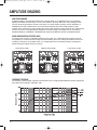
1
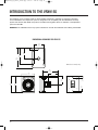
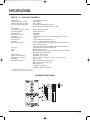
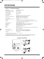
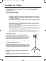
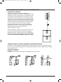
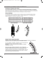
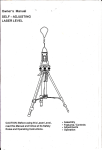
VRXpassive_UG_091907_final.qxp
9/20/07
4:56 PM
Page 1
V
V
R
V
R
X
R
X
9
X
User’s Guide
V
V
9
3
2
L
A
1
W
H
8
S
3
2
L
A
V
R
X
9
9
1
8
S
-
W
H
V
R
X
9
1
5
M
R
X
9
2
8
L
A
V
R
X
9
1
5
S
V
R
X
-
A
F
X
-
M
A
F
R
S
-
-
1
VRXpassive_UG_091907_final.qxp
2
9/20/07
4:56 PM
Page 2
VRXpassive_UG_091907_final.qxp
9/20/07
4:56 PM
Page 3
CONTENTS
Introduction to the VRX932LA-1
VRX932LA-1 Specifications
Introduction to the VRX928LA
VRX928LA Specifications
Introduction to the VRX918S
VRX918S Specifications
Introduction to the VRX915S
VRX915S Specifications
Introduction to the VRX915M
VRX915M Specifications
Amplitude Shading
System Processor Tunings
Deploying the System
Suspension Safety Warnings
Introduction to the VRX-AF
Introduction to the VRX-SMAF
JBL Warranty and Information
4
5
6
7
8
9
10
11
12
13
14-15
15
16-17
18-20
21
22
23
IMPORTANT SAFETY INSTRUCTIONS
The VRX Series loudspeakers covered by this manual are not intended for fixed installation in outdoor or high
moisture environments. Moisture can damage the speaker cone and surround and cause corrosion of electrical
contacts and metal parts. Avoid exposing the speakers to direct moisture. Keep speakers out of extended or
intense direct sunlight. The driver suspension will prematurely dry out and finished surfaces may be degraded by
long-term exposure to intense ultra-violet (UV) light.
The VRX Series speakers can generate considerable energy. When placed on a slippery surface such as
polished wood or linoleum, the speaker may move due to its acoustical energy output. Precautions should be
taken to assure that the speaker does not fall off a stage or table on which it is placed.
1. Read these instructions.
2. Keep these instructions.
10. Use only with a cart, stand, bracket, or table specified by the
manufacturer or sold with the apparatus. When a cart is used, use
caution when moving the cart / apparatus combination to avoid
injury from tip-over.
3. Heed all warnings.
4. Follow all instructions.
5. Do not use this apparatus near water.
6. Clean only with a dry cloth.
7. Do not block any ventilation openings. Install in accordance
with manufacturer’s instructions.
8. Do not install near any heat sources such as radiators, heat
registers, stoves, or other apparatus that produce heat.
9. Only use attachments / accessories specified by the manufacturer.
11. Refer all servicing to qualified service personnel.
Servicing is required when an apparatus has been
damaged in any way, such as power-cord or plug
is damaged, liquid has been spilled, or objects
have fallen into the apparatus, the apparatus has
been exposed to rain or moisture, does not
operate normally, or has been dropped.
12. To reduce the risk of fire or electric shock, do not expose this
apparatus to rain or moisture.
13. Hearing damage, prolonged exposure to excessive SPL, the
loudspeaker is easily capable of generating sound pressure levels
(SPL) sufficient to cause permanent hearing damage to performers,
production crew and audience members. Caution should be taken
to avoid prolonged exposuro SPL in excess of 90 dB.
PATENTS
VRX series products are manufactured and sold under U.S. patents 5,748,760; 6,112,847; 6,394,223; 6,847,726;
6,774,510; D483,743; 6,768,806; and D483,744.
3
VRXpassive_UG_091907_final.qxp
9/20/07
4:56 PM
Page 4
INTRODUCTION TO THE VRX932LA-1
The VRX932LA-1 is a two-way, line-array loudspeaker system intended for use in arrays of up to six enclosures.
Three high-frequency drivers are mounted to the Constant Curvature waveguide which is designed so that
multiple enclosures may be arrayed with no discontinuity in the vertical coverage pattern. As a result, the array
will behave in much the same way as would a single loudspeaker. Array coverage may be adjusted by means
of the Array Configuration Selector (ACS), a feature that provides amplitude shading (see page 14 & 15) when
the system is used in passive mode. Integral rigging hardware, a dual angle pole socket and an accessory array
frame provide for a variety of mounting and suspension options.
NOTE: The VRX932LA-WH is designed for fixed install situations where white loudspeakers are required to
match existing decor. White versions therefore do not have handles, feet or pole mount features.
DIMENSIONAL DRAWINGS FOR VRX932LA-1
Equipped with Differential Drive
Transducer Technology U.S. PATENT 5,748,760
Single
Speaker
or
Short
Throw
Mid
Throw
Long
Throw
Array Configuration Selector - HF Output Level
BI-AMP
PASSIVE
349
(13.75)
15
o
PASSIVE
±1 IN: 6W
±2 N/C
PARALLEL
VRX932LA
Serial No.
BI-AMP
±1 LF: 8W
±2 HF: 6W
JBL PROFESSIONAL
Northridge, CA USA
Made in USA
Dimensions in mm (inches)
376
(14.8)
R: 1325
(52.2)
597
(23.5)
4
VRXpassive_UG_091907_final.qxp
9/20/07
4:56 PM
Page 5
SPECIFICATIONS
VRX932LA-1 - 12", TWO-WAY, LINE-ARRAY LOUDSPEAKER SYSTEM
System Type:
Frequency Range (-10 dB) 1:
Frequency Response (±3 dB) 1:
Coverage Pattern:
Crossover Modes:
Crossover Frequency:
Power Rating
(Continuous 2 / Program / Peak):
12" two-way, line array loudspeaker system
57 Hz - 20 kHz
75 Hz - 20 kHz
100º x 15º nominal (horizontal x vertical)
Bi-amp / passive, externally switchable
1.2 kHz
Passive: 800 W / 1600 W / 3200 W
Bi-amp LF: 800 W / 1600 W / 3200 W
Bi-amp HF: 75 W / 150 W / 300 W
130 dB SPL peak (passive)
LF: 130 dB
HF: 139 dB
95 dB SPL (passive mode)
LF: 95 dB
HF: 114 dB
1 x JBL 2262H 305 mm (12 in) Differential Drive® woofer with
neodymium-magnet and dual voice-coils
3 x JBL 2408J, 38 mm (1.5 in) voice-coil, neodymium magnet
compression driver
Passive: 8 ohm
Bi-amp LF: 8 ohms
Bi-amp HF: 8 ohms
Tunings available at www.jblpro.com
18 mm, 11-ply birch plywood.
Suspension requires optional VRX-AF line-array frame kit /
Dual angle 36 mm pole socket / 10 mm eyebolt
Black DuraFlex™ finish
Powder coated, black, 16-gauge perforated steel with acoustically
transparent foam
Neutrik® Speakon® NL-4 (x2)
349 mm x 597 mm x 376 mm (13.75 in x 23.5 in x 14.8 in)
21 kg (46 lb)
VRX-AF: Suspension array frame
SS2-BK: Tripod speaker stand
SS3-BK: Satellite Speaker Pole
SS4-BK: Adjustable Satellite Speaker Pole to be used with VRX918S and
SRX718S only.
M10 Eyebolt Kit (Part # 229-00009-01)
System Maximum SPL 3:
System Sensitivity (1w @ 1m):
LF Driver:
HF Driver:
Nominal Impedance:
Active Tunings:
Enclosure:
Suspension / Mounting 4:
Finish 5:
Grille 6:
Input Connectors:
Dimensions (H x W x D):
Net Weight:
Optional Accessories:
1.
2.
3.
4.
5.
6.
“Frequency Range” and “Frequency Response” are based on half-space conditions.
IEC filtered noise with 6 dB crest factor, 2 hours.
Calculated based on power rating and sensitivity.
White version does not include pole mount feature.
White version uses JBL Pro White Duraflex Finish.
White version grille is powdercoated white with acoustically transparent white cloth backing.
FUNCTIONAL BLOCK DIAGRAM
LONG THROW
+3 dB
-
0 dB
+
MID THROW
HPF
+
-
-
+
+
NL4
INPUT
1+
12+
2-
-3 dB
SHORT THROW
NL4
INPUT
+
2+
2-
+
-
BI-AMP
MODE
PASSIVE
MODE
NL4
INPUT
1+
1-
1+
12+
2-
LPF
+
-
NL4
INPUT
1+
1-
+
-
2+
2-
5
VRXpassive_UG_091907_final.qxp
9/20/07
4:56 PM
Page 6
INTRODUCTION TO THE VRX928LALA
The VRX928LA – the smaller version of the VRX932LA is a light-weight, compact, 8", two-way line-array
speaker system designed for use in arrays of up to six units. VRX928LA is the ideal choice when line-array
performance is needed but the venue size doesn't call for the very long-throw characteristics of larger
line-arrays. The VRX928LA offers all the same features as the VRX932LA. As with the VRX932LA, the Array
Configuration Selector (ACS) makes it possible to distribute the sound more evenly over the entire audience
area, by reducing the output near the stage and increasing it for the far to reach rear areas. (See page 14 & 15)
NOTE: A white version is available for this product through our custom shop.
Contact your JBL dealer or rep. for details
DIMENSIONAL DRAWINGS FOR VRX928LA
419
(16.5)
267
(10.5)
127
(5.0)
209
(8.3)
115
(4.5)
230
(9)
0
15
876
(R:34.5)
Dimensions in mm (inches)
6
VRXpassive_UG_091907_final.qxp
9/20/07
4:56 PM
Page 7
SPECIFICATIONS
VRX928LA - 8", TWO-WAY, LLNE-ARRAY SPEAKER
System Type:
Frequency Range (-10 dB):
Frequency Response (±3 dB):
Coverage Pattern:
Crossover Modes:
Crossover Frequency:
Power Rating 1:
(Continuous / Program / Peak)
System Maximum SPL 2:
System Sensitivity (1 W @ 1m)
LF Driver:
HF Driver:
Nominal Impedance:
Active Tunings:
Enclosure:
Suspension / Mounting:
Transport:
Finish:
Grille:
Input Connectors:
Dimensions (H x W x D):
Net Weight:
Optional Accessories:
8" two way, line array loudspeaker system
70Hz -20kHz
87Hz - 19kHz
100º x 15º nominal (horizontal x vertical), single unit
Bi-amp / passive, externally switch-able
2.0 KHz
400 W / 800 W / 1600W
Bi-amp LF: 400 W / 800 W / 1600W
Bi-amp HF: 30 W / 60 W / 120 W (two drivers)
122dB SPL (passive mode)
LF: 122 dB
HF: 128 dB
90 dB SPL (passive mode)
LF: 90 dB
HF: 108 dB
1 x JBL 2168H-1, 200 mm (8 in) Differential Drive® woofer
2 x JBL 2414H, 25 mm (1.0 in) neodymium compression driver
Passive: 8 Ohms
Bi-amp LF: 8 Ohms
Bi-amp HF: 16 Ohms
Tunings available at www.jblpro.com
15 mm - 25 mm, multi ply birch plywood
Dual 36mm pole socket included. Suspension requires optional
VRX-SMAF line array frame kit or 10 mm eyebolt.
Integrated handle with backing cup
Black DuraFlex™ finish
Powder coated, black, 18 gauge perforated steel with acoustical
transparent black foam backing.
2x Neutrik® Speakon NL-4
230 mm x 419 mm x 267 mm (9 in x 16.5 in x 10.5 in)
12.7 kg (28 lb.)
VRX-SMAF: Suspension array frame
SS2-BK: Tripod speaker stand
Eyebolt Kit (Part # 229-00009-01)
1 IEC filtered noise with 6 dB crest factor, 2 hours.
2 Calculated, based on power rating and sensitivity.
FUNCTIONAL BLOCK DIAGRAM
7
VRXpassive_UG_091907_final.qxp
9/20/07
4:56 PM
Page 8
INTRODUCTION TO THE VRX918S
The VRX918S is a compact, single, 18" direct radiating subwoofer intended for use in suspended arrays or
ground-supported applications. The suspension system is designed for full compatibility with the VRX932LA-1
line-array speaker system and the VRX-AF array frame.
NOTE:
The VRX918S-WH is designed for fixed installation situations where white loudspeakers are required to match
existing decor. White versions therefore do not have handles, feet or pole mount features.
DIMENSIONAL DRAWINGS FOR VRX918S
749
(29.5)
254
(10.0)
546
(21.5)
597
(23.5)
464
(18.25)
79
(3.13)
298
(11.75)
457
(18.0)
508
(20.0)
60
(2.37)
235
(9.25)
8
(0.3)
44
(1.75)
38
(1.5)
489
(19.25)
56
(2.2)
610
(24.0)
Dimensions in mm (inches)
406
(16.0)
45
(1.8)
8
508
(20.0)
51
(2.0)
VRXpassive_UG_091907_final.qxp
9/20/07
4:56 PM
Page 9
SPECIFICATIONS
VRX918S - 18" BASS-REFLEX SUBWOOFER
System Type:
Frequency Range (-10 dB) 1:
Frequency Response (±3 dB) 1:
Input Connection Modes:
Recommended Crossover:
Power Rating
(Continuous 2 / Program / Peak)
Maximum SPL 3 :
Sensitivity (1w @ 1m):
LF Driver:
Nominal Impedance:
Active Tunings:
Mounting 4:
Suspension / Mounting:
Enclosure:
Finish 5:
Grille 6:
Input Connectors:
Dimensions (H x W x D):
Net Weight:
Optional Accessories:
130 dB SPL peak
95 dB SPL
1 x JBL 2268H 457 mm (18 in) Differential Drive woofer
8 ohms
Use SRX718S tunings
Optional VRX-AF line array frame kit or 10mm eyebolt
(Part #229-00009-01)
Top mounted M20 threaded socket for optional SS4-BK pole
Rectangular, 18 mm, 13-ply birch plywood
Black DuraFlex finish
Powder coated, 16-gauge perforated steel with acoustical transparent
charcoal foam backing.
Neutrik® Speakon® NL-4 (x2)
508 mm x 597 mm x 749 mm; (20.0 in x 23.5 in x 29.5 in)
37 kg (81 lb)
SRX718S-CVR: Pull-over padded cover
SS4-BK: Adjustable, heavy-duty pole,
M20 thread to 35 mm pole mount
WK-4: Caster kit
VRX-AF Array Frame
Eyebolt Kit (Part #229-00009-01)
“Frequency Range” and “Frequency Response” are based on half-space conditions.
IEC filtered noise with 6 dB crest factor, 2 hours.
Calculated based on power rating and sensitivity.
White version does not include pole mount feature.
White version uses JBL Pro White Duraflex Finish.
White version grille is powdercoated white with acoustically transparent white cloth backing.
FUNCTIONAL BLOCK DIAGRAM
VRX918S
1.
2.
3.
4.
5.
6.
18" bass-reflex subwoofer
31 Hz - 220 Hz
34 Hz - 220 Hz
Switchable, +1/-1 or +2/-2
High-pass: Butterworth 18 dB/oct, 31 Hz
Low-pass: Linkwitz-Riley 48 dB/oct, 80 Hz
800 W / 1600 W / 3200 W
9
VRXpassive_UG_091907_final.qxp
9/20/07
4:56 PM
Page 10
INTRODUCTION TO THE VRX915S
The VRX915S a very compact single 15" direct radiating subwoofer is intended as companion subwoofer
for the VRX928LA. The suspension system is designed for full compatibility with the VRX928LA Line Array
System and with the VRX-SMAF array frame. The M20 mounting plate allows for utilization of the adjustable
pole mount SS4-BK.
WARNING: The VRX928LA is the only system intended for use with the VRX915S when utilizing the SS4-BK.
DIMENSIONAL DRAWINGS FOR VRX915S
314
(12.4)
41
(1.6)
318
(12.5)
478
(18.8)
597
(23.5)
Dimensions in mm (inches)
478
(18.8)
420
(16.5)
328.24
(12.9)
248
(9.8)
500.13
(19.7)
43
(1.7)
496
(19.5)
43
(1.7)
10
VRXpassive_UG_091907_final.qxp
9/20/07
4:56 PM
Page 11
SPECIFICATIONS
VRX915S - 15", BASS-REFLEX SUBWOOFER
System Type:
Frequency Range (-10 dB):
Frequency Response (±3 dB):
Recommended Hi-Pass Filter:
Power Rating 1:
(Continuous / Program / Peak)
Recommended EQ:
Maximum SPL 2:
Sensitivity (1 W @ 1m)
LF Driver:
Nominal Impedance:
Active Tunings:
Enclosure:
Suspension / Mounting:
Transport:
Finish:
Grille:
Input Connectors:
Input connection modes:
Dimensions (H x W x D):
Net Weight:
Optional Accessories:
15" bass reflex subwoofer
35Hz -250Hz
40Hz - 250Hz
HP: Butterworth 24 dB/octave, 45 Hz
LP: Linkwitz-Riley 48 dB/octave, 80 – 120Hz
800 W / 1600 W / 3200W
+2dB at 45Hz, Q: 2.5
126 dB SPL
91 dB SPL
1 x JBL 2265G-1, 250 mm (15 in) Differential Drive® woofer
4 Ohms
Tunings available at www.jblpro.com
15 mm - 18 mm, multi ply birch plywood
Top mounted M20 threaded socket for optional pole SS4-BK. In
tegrated flying hardware
for use with array frame VRX-SMAF. Optional M10 eyebolt kit.
Integrated steel handle with backing cup
Black DuraFlex™ finish
Powder coated, black, 18 gauge perforated steel with acoustical
transparent black foam backing.
2x Neutrik® Speakon NL-4
Switchable, +1/-1 or +2/-2
496 mm x 420 mm x 597 mm (19.5 in x 16.5 in x 23.5 in)
26 kg (57 lb.)
SS4-BK: Adjustable, heavy-duty pole,
M20 thread to 35 mm pole mount
WK-4: Caster kit
VRX-SMAF Array Frame
Eyebolt Kit (Part #229-00009-01)
1 IEC filtered noise with 6 dB crest factor, 2 hours.
2 Calculated, based on power rating and sensitivity.
FUNCTIONAL BLOCK DIAGRAM
4 Ohms
11
VRXpassive_UG_091907_final.qxp
9/20/07
4:56 PM
Page 12
INTRODUCTION TO THE VRX915M
The VRX915M is a dedicated, compact and lightweight, 15", two way touring-class floor monitor, with only
a 375 mm (14.75 in) stage height and JBL’s latest neodymium-magnet transducers.
A 380 mm (15 in) 2265H patented Differential Drive® woofer handles 800 watts (continuous) and delivers
accurate and precise low frequency reproduction. The 2452H 102 mm (4 in) voice-coil compression driver is
coupled to a 50° x 90° aluminum horn to provide smooth and clear high frequency reproduction, critical for high
performance monitoring.
Bi-amp or full-range passive operation may be selected via a recessed, high-current switch mounted alongside
the NL4 input connector in one of the handle cups. An additional NL4 connector is mounted in the other handle
cup for a convenient loop-thru connection, minimizing cable runs on stage.
The enclosure is constructed of top quality Baltic birch plywood and is coated in JBL’s rugged DuraFlex™
finish. It is a symmetrical 30° wedge design, with four non-slip rubber feet per side enabling convenient left and
right applications of adjacent monitors. The transducers are protected by an attractive 16 gauge CNC-machined
steel grille, which is internally lined with acoustically transparent foam to provide additional transducer protection.
DIMENSIONAL DRAWING FOR VRX915M
546
(21.51)
191
(7.51)
324
(12.75)
375
(14.75)
432
(17.00)
Dimensions in mm (inches)
629
(24.75)
12
159
(6.25)
VRXpassive_UG_091907_final.qxp
9/20/07
4:56 PM
Page 13
SPECIFICATIONS
VRX915M - 15” TWO-WAY STAGE MONITOR
System Type:
Frequency Range (-10 dB):
Frequency Response (±3 dB):
Coverage Pattern:
Crossover Modes:
Crossover Frequency:
Power Rating:
(Continuous / Program / Peak)
15" Two-way Stage Monitor
60 Hz - 20 kHz
70 Hz - 20 kHz
50° x 90° nominal
Passive / Bi-amp
1.1 kHz
Passive Full-Range 800 W / 1600 W / 3200 W, 2 hrs 1
Bi-amp LF: 800 W / 1600 W / 3200 W, 2 hrs 1
Bi-amp HF: 75 W / 150 W / 300 W, 2 hrs 1
127 dB SPL continuous (133 dB SPL peak) 2
98 dB SPL
1 x JBL 2265H, 380 mm (15 in) Differential Drive® woofer 8 Ohms
1 x JBL 2452H, 100 mm (4.0 inch) diameter voice coil, 38 mm (1.5 inch) exit,
neodymium magnet compression driver 8 Ohms
8 Ohms Full-Range Passive
Settings available at http://www.jblpro.com/tunings/index.htm
Symmetrical stage monitor, 15/18 mm, Birch plywood.
2x Integrated handle / input cup
Black DuraFlex™ finish
Powder coated, black, 16 gauge perforated steel with acoustically transparent
black screen backing.
Neutrik® Speakon® NL-4 (x2), one on each end
629 mm x 432 mm x 324 mm (375 mm stage height)
24.75 in x 17 in x 12.75 in (14.75" stage height)
21 kg (46.0 lb)
Maximum SPL:
System Sensitivity (1w @ 1m):
LF Driver:
HF Driver:
Nominal Impedance:
Active Tunings:
Enclosure:
Transport:
Finish:
Grille:
Input Connectors:
Dimensions (H x W x D):
Net Weight:
1.
2.
IEC standard, full bandwidth pink noise with 6 dB crest factor for specified period
Calculated based on power rating and sensitivity.
JBL continually engages in research related to product improvement. Some materials, production methods and design refinements are introduced
into existing products without notice as a routine expression of that philosophy. For this reason, any current JBL product may differ in some respect
from its published description, but will always equal or exceed the original design specifications unless otherwise stated.
FUNCTIONAL BLOCK DIAGRAM
NL4
IN / THRU
1+
1-
HPF
HIGH
FREQ
+
2+
2-
+
LOW
FREQ
PASSIVE
MODE
VRX900
BI-AMP
±1 LF: 8 W
±2 HF: 8 W
Serial No.
PASSIVE
BI-AMP
VRX915M
JBL PROFESSIONAL
Northridge, CA USA
Made in USA
NL4
IN / THRU
PASSIVE
±1 IN: 8 W
±2 N/C
1+
1-
LPF
2+
2-
+
NL4
IN / THRU
1+
12+
2-
HIGH
FREQ
+
LOW
FREQ
BI-AMP
MODE
NL4
IN / THRU
1+
12+
2-
13
VRXpassive_UG_091907_final.qxp
9/20/07
4:56 PM
Page 14
AMPLITUDE SHADING
AMPLITUDE SHADING
Amplitude shading is a technique that allows the coverage pattern of a loudspeaker array to be shaped by
adjusting the relative acoustic output of some of the devices in the array. Most often, array shading involves
only the mid and high-frequency sections of the array. In a simple system consisting of three VRX932LA-1/
VRX928LAs, the lower speaker (which covers the nearest listeners) may have its high-frequency output
reduced. At the same time, the upper speaker may have its high frequency output increased. The overall soundpower in the room is unchanged but the distribution of acoustic energy to the audience is far more uniform.
Amplitude shading of a VRX932LA-1/ VRX928LA array may be accomplished in passive or bi-amplified systems.
ARRAY CONFIGURATION SELECTOR (ACS)
In passive mode, the Array Configuration Selector may be used. The -3 dB position will typically be used for
the speaker(s) in an array that are covering the nearest listening area. The +3 dB position will be used for the
speaker(s) covering the more distant areas; or to compensate for the low-frequency build-up resulting from
mutual coupling of multiple woofers in an array.
Short Throw (-3 dB)
Medium Throw (0 dB)
Long Throw (+3 dB)
FREQUENCY RESPONSE
The frequency response graph represents measurements from a single typical VRX900LA speaker, applying the
three different ACS settings: +3dB, 0dB, -3dB.
14
VRXpassive_UG_091907_final.qxp
9/20/07
4:56 PM
Page 15
ARRAY CONFIGURATION SELECTOR (ACS)
Below is an example of applying the ACS in a three-speaker array. In this particular configuration, the ACS on
the top speaker is set at +3 dB, the middle speaker at 0 dB, and the bottom speaker -3 dB.
+3 dB
0 dB
-3 dB
Audience
BI-AMPLIFIED SYSTEM
In a bi-amplified system, array shading is accomplished by connecting separate amplifier channels to the HF
section of each VRX932LA-1/VRX928LA. In larger arrays, a single amplifier channel may be used for two
adjacent loudspeakers. Array shading is then accomplished by adjusting the gain of the HF amplifier channels.
For extremely precise control over system performance, it may also be desirable to dedicate an individual
system controller output to each HF amplifier channel.
SYSTEM PROCESSOR TUNINGS
Please visit www.jblpro.com/tunings for latest versions of our recommended system tunings or call customer
service at Toll Free 1-800-852-5776.
15
VRXpassive_UG_091907_final.qxp
9/20/07
4:56 PM
Page 16
DEPLOYING THE SYSTEM
All of the information in this section for VRX932LA-1 also applies to previous VRX932LA systems.
The VRX932LA-1/VRX932LA-WH are flexible speaker systems that can be deployed in ground-supported or
suspended applications. The following information will help you set up your VRX932LA-1/VRX932LA-WH
system safely and effectively.
POLE AND TRIPOD SAFETY WARNINGS!
When using stands or poles, be sure to observe the following precautions:
• Check the stand or pole specification to be certain the device is designed to support the weight of
the speaker. Observe all safety precautions specified by the manufacturer.
• Be certain that the surface on which the system is to be stacked is flat, stable and solid.
• Route cables so that performers, production crew, and audience will not trip and topple the speakers.
• Inspect the stand (or pole and associated hardware) before each use and do not use equipment with
worn, damaged, or missing parts.
• Do not attempt to place more than two VRX932LA-1/VRX932LA-WH loudspeakers on a stand or pole.
• When mounting two VRX932LA-1/VRX932LA-WH speakers on a pole or tripod, integral rigging
hardware must be used to secure the speakers to each other.
• Always be cautious when deploying the system outdoors. Unexpected winds may topple a system.
It may be necessary to place additional weight (i.e.sandbags) on the base of the stand to improve
stability. Avoid attaching banners or similar items to any part of a speaker system. Such attachments
could act as a sail and topple the system.
• Unless you are confident that you can handle the weight of the speaker, ask another person to help
you get it onto the tripod stand or pole.
• One or two VRX932LA-1 cabinets may be mounted onto either a JBL SS2-BK tripod stand or with the
SS4-BK adjustable pole mount to their companion VRX918S or SRX718S subwoofers. Do not mount
VRX932LA-1 cabinets on top of the compact VRX915S subwoofer!
• One or two VRX928LA cabinets maybe mounted onto either a JBL SS2-BK tripod stand or their
companion subwoofer VRX915S. The larger type subwoofer SRX718S/ VRX918S can also be used.
SINGLE VRX932LA-1/VRX928LA
A single VRX932LA-1 may be used on a tripod stand (JBL SS2-BK) or on a
pole (JBL SS4-BK) over its companion subwoofer the VRX918S or the
SRX718S. The use of a subwoofer is recommended for applications requiring
more low-frequency power and extension. Usually, the Array Configuration
Selector (ACS) switches on the input panel should be set to the “Short Throw
(-3 dB)” position when a single speaker is used.
A single VRX928LA may be used on a tripod stand (JBL SS2-BK) or on a pole
(JBL SS4-BK) over its compact companion subwoofer the VRX915S or the
larger VRX918S/SRX718S subwoofer models.
The VRX932LA-1/VRX928LA includes a dual angle 36 mm pole mount socket.
By selecting the appropriate pole socket and adjusting the height of the tripod
or pole, optimum coverage may be achieved. Ideally, the audience should not
be able to see either he bottom or the top surfaces of the speaker. This will
insure that all listeners are within the "included coverage angle" of the loudspeaker. The rear pole-socket will position the speaker with the baffle 2.5° to
the floor while the forward socket will position the speaker with the baffle
angled down by 15°. System illustration shows the available JBL SS2-BK
tripod stand.
NOTE: VRX932LA-WH does not include pole mount features and is designed
specifically for fixed installations.
16
VRXpassive_UG_091907_final.qxp
9/20/07
4:56 PM
Page 17
All of the information in this section for VRX932LA-1 also applies to previous VRX932LA systems.
DUAL VRX932LA-1/VRX928LA
Unlike most conventional speakers, the VRX932LA-1/
VRX928LA is designed so that a pair of speakers may be safely
mounted onto a pole or tripod stand. For most applications, the
forward socket of the dual angle pole socket will be used. This
will tilt the lower of the two speakers at a 15° down-angle (providing
coverage of the near listeners) while the upper speaker will face
straight out (covering the more distant areas). Ideally, the listeners
should not be able to see either the bottom or the top surfaces
of the two-speaker array. Usually, the Array Configuration
Selector (ACS) switches on the lower speaker's input panel
should be set to the “Short Throw (-3 dB)” position while the
upper speaker will be set to either “Short Throw
(-3 dB)” or “Mid Throw (0 dB)”.
Place the speakers on the pole or tripod one at a time. Be sure
to lock the two speakers together using the integral rigging
hardware (see below). System illustration shows available JBL
SS4-BK speaker pole and SRX718S subwoofers. Do not stack
more than two VRX932LA-1/ VRX928LA speakers on a pole.
LOCKING (2) VRX932LA-1/VRX932LA-WH/VRX928LA LOUDSPEAKERS TOGETHER
Any time two or more VRX932LA-1/VRX928LAs are arrayed together, they must be mechanically secured to
each other using the integral rigging frame and supplied quick release pins. See the diagram below for details.
Safe combinations are:
VRX918S with VRX932LA-1
VRX915S with VRX928LA
WARNING: Only the correct quick release pins supplied by JBL are to be used.
17
VRXpassive_UG_091907_final.qxp
9/20/07
4:56 PM
Page 18
SUSPENSION SAFETY WARNINGS!
All of the information in this section for VRX932LA-1 also applies to previous VRX932LA systems.
Correct use of all rigging hardware is required for secure system suspension. Careful calculations should
always be performed to ensure that all components are used within their Maximum Load Limit before the array
is suspended. Never exceed the maximum recommended load ratings. Prior to suspending the system, an
expert, trained and experienced in flying speaker systems should be consulted. Research and understand the
codes, practices, and requirements in the venues where you intend to operate your sound system.
INSPECTION & MAINTENANCE
Before suspending or pole mounting any speaker system always inspect all components (enclosure, rigging
frames, pins, eyebolts, track fittings, etc.) for cracks, deformations, corrosion, missing, loose or damaged
parts that could reduce strength and safety of the array. Do not suspend or pole mount the speaker until the
proper corrective action has been taken. Installed systems should be inspected at least annually. The inspection
shall include a visual survey of all corners and load bearing surfaces for signs of cracking, water damage,
de-lamination, or any other condition that may decrease the strength of the loudspeaker enclosure. Accessory
rigging hardware provided with or for the JBL VRX932LA-1/VRX932LA-WH/VRX928LA or VRX918S/VRX915S
loudspeaker must be inspected for fatigue at least annually or as required by local ordinance. For all other
hardware and fittings, refer to the hardware manufacturer's inspection and maintenance guidelines for process.
ARE YOU NEW TO RIGGING?
If you are new to rigging, you should do the following:
• Read and study JBL Technical Note Volume 1, Number 14: Basic Principles for Suspending
Loudspeaker Systems (available at http://www.jblpro.com/pub/technote/tn_v1n14.pdf).
• Know the rules for safe rigging.
• Attend a safe rigging seminar, such as that presented by professionals like Rigging Seminars™
(www.riggingseminars.com) or by Chain Motor Hoist manufacturers like Columbus McKinnon Corp.
(manufacturers of the C/M Lodestar).
• Meet and establish a relationship with a licensed mechanical or structural engineer. Get in the habit
of asking them questions instead of guessing about their answers. Learn from what they tell you.
• Meet and discuss this aspect of your business with your Insurance Agent.
ATTACHMENT TO STRUCTURES
A licensed Professional Engineer must approve the placement and method of attachment to the structure prior
to the installation of any overhead object. The following performance standards should be provided to the
Professional Engineer for design purposes; Uniform Building Code as applicable, Municipal Building Code as
applicable, and Seismic Code as applicable. The installation of the hardware and method of attachment must
be carried out in the manner specified by the Professional Engineer. Improper installation may result in
damage, injury or death.
JBL is not responsible for the application of its products for any purpose or the misuse of this information for any
purpose. Furthermore, JBL is not responsible for the abuse of its products caused by avoiding compliance with
inspection and maintenance procedures or any other abuse.
18
VRXpassive_UG_091907_final.qxp
9/20/07
4:56 PM
Page 19
All of the information in this section for VRX932LA-1 also applies to previous VRX932LA systems.
MAXIMUM ARRAY SIZE
There are three variations of the VRX array frame. The VRX-AF supersedes the VRX932LA-AF. The VRX-SMAF
is solely intended for use with the VRX928LA and VRX915S. Before suspending a VRX array, determine which
version of the array frame you have and consult the table below to determine the maximum number of speakers
that may be safely suspended. The subwoofers must always be at the top of the array.
VRX-AF Array Frame
VRX-AF ARRAY FRAME
The following table defines the maximum number of speakers that may be suspended using the VRX-AF frame. A
minimum design factor of 7:1 is maintained for all speaker configurations at or below those indicated in the table.
Maximum number of VRX918S in array
6
5
4
3
2
1
0
Maximum number of VRX932LA-1 in array
0
1
2
3
4
5
6
VRX932LA-AF Array Frame
VRX932LA-AF ARRAY FRAME
The following table defines the maximum number of speakers that may be suspended using the VRX932LA-AF frame.
A minimum design factor of 7:1 is maintained for all speaker configurations at or below those indicated in the table.
Maximum number of VRX918S in array
Maximum number of VRX932LA-1 in array
4
3
2
1
0
1
2
3
4
5
VRX-SMAF Array Frame
VRX-SMAF ARRAY FRAME
The following table defines the maximum number of speakers that may be suspended using the VRX-SMAF
array frame. A minimum design factor of 7:1 is maintained for all speaker configurations at or below those
indicated in the table.
Maximum number of VRX915S in array
4
3
2
2
2
0
Maximum number of VRX928LA in array
0
2
3
4
5
6
The VRX subwoofers must always be on top of the array.
INSTALLING THE ARRAY FRAME
The array frame is attached to the internal rigging of the VRX900 system using the provided Quick Release Pins
WARNING: Do not use any substitute for these pins.
1. Begin by attaching the two side arms (A) to either side of the center frame. Use a pair of the provided Quick
Release Pins (B)* to attach the arms to the frame. Note: Side arms should be attached
with the rubber bumper facing up and away from the center
(B)* (A)
(D)
frame. The center frame is installed with the rubber gasket
(A)
(D)
toward the enclosure and the label right side up. [NOTE: The
arms of the VRX932LA-AF and VRX-AF are deliberately
(C)
designed so as not to be interchangeable. The arms of the
VRX-SMAF are already attached.
2. Place the entire array frame on top of the VRX900 system
and flip up the drop levers (C) found on both sides of the
speaker to be received by the array frame arms.
3. Once the drop levers on the speaker are received by the
array frame, use a pair of the provided Quick Release Pins
(D) to attach the drop levers to the array frame.
*(B) does not apply to VRX-SMAF
19
VRXpassive_UG_091907_final.qxp
9/20/07
4:56 PM
Page 20
All of the information in this section for VRX932LA-1 also applies to previous VRX932LA systems.
SUSPENSION IN PERMANENT INSTALLATIONS
For permanent installation applications a VRX array may be suspended using M10 eyebolts. Only load-rated,
forged shoulder eyebolts are to be used. A kit consisting of three (3) forged shoulder eyebolts is available from
JBL Professional as part number 229-00009-01. Suspension of the VRX array must employ both top attachment
points. The VRX918S and VRX915S subwoofers must always be at the top of the array.
EYEBOLT SUSPENSION
The following table defines the maximum number of speakers that may be suspended using the two M10
eyebolt attachment points provided on the cabinets. A minimum design factor of 7:1 is maintained for all
speaker configurations at or below those indicated in the table.
Maximum number of VRX918S in array
5
4
3
2
1
0
Maximum number of VRX932LA-1 in array
0
2
4
5
6
6
Maximum number of VRX915S in array
4
3
2
2
2
0
Maximum number of VRX928LA in array
0
2
3
4
5
6
EYEBOLT SUSPENSION
ARRAY FRAME SUSPENSION
GROUND-STACKED, UPWARD FIRING ARRAYS
Applications such as covering stadium bleachers from the playing field may be addressed by installing the
VRX932LA-AF/VRX-AF/VRX-SMAF array frame to the bottom of the array.
Up to four VRX932LA-1/VRX928LA loudspeakers may be locked together and
ground stacked using the VRX array frame kit, as shown.
WARNING: Do not ground stack more than four VRX932LA-1/VRX928LA
loudspeakers in one array.
When ground stacking VRX900LA loudspeakers, use the VRX932LA-AF/
VRX-AF/VRX-SMAF array frame as the base (as shown) by attaching the loose
drop levers, included in the array frame kit, to the lower rigging bar on the
VRX900LA loudspeaker. When stacking the loudspeakers together, make sure
each loudspeaker is locked together. Be certain that the surface on which the
system is to be stacked is flat, stable and solid.
20
VRXpassive_UG_091907_final.qxp
9/20/07
4:56 PM
Page 21
INTRODUCTION TO THE VRX-AF
The VRX-AF is an array frame designed to be used for suspension of the VRX932LA-1 and VRX918S
loudspeaker systems. The optional array frame kit includes the following items:
•
•
•
•
•
1
2
4
2
2
x
x
x
x
x
center frame
side arms
quick release pins
drop levers
3/8˝ shackles
WORKING LOAD LIMIT
The VRX-AF, VRX932LA-AF, and VRX-SMAF array frames have been precisely engineered to work together
with the VRX line of speakers as a system. The working load limit depends upon the configuration of array
frame and speakers being suspended. Please refer to the “DEPLOYING THE SYSTEM” section of this user
guide for maximum allowable load limits when using the VRX-AF, VRX-SMAF or VRX932LA-AF frame.
Use of the array frames in any manner other than as described in this manual could result in
damage to the frame and pose a risk of injury or death.
DIMENSIONAL DRAWINGS FOR VRX-AF
635
(25)
445
(17.5)
51
(2.0)
13
(0.5)
25
(1.0)
65
(2.5)
65
(2.5)
65
(2.5)
65
(2.5)
330
(13.0)
25
(1.0)
38
(1.5)
292
(11.5)
117
(4.6)
10
(0.4)
610
(24.0)
Dimensions in mm (inches)
21
VRXpassive_UG_091907_final.qxp
9/20/07
4:56 PM
Page 22
INTRODUCTION TO THE VRX-SMAFMAF
The VRX-SMAF is an array frame designed to be used for suspension of the VRX928LA and VRX915S
loudspeaker systems. The optional array frame kit includes the following items:
•
•
•
•
1
2
2
2
x
x
x
x
frame
quick release pins
drop levers
3/8" shackles
WORKING LOAD LIMIT
The working load limit depends upon the configuration of array frame and speakers being suspended.
Please refer to the “DEPLOYING THE SYSTEM” section of this user guide for maximum allowable load
limits when using the VRX-SMAF frame.
The VRX-SMAF array frame has been specifically designed to work only with the VRX928LA and VRX915S
speakers. Use of the array frames in any manner other than as described in this manual could result in
damage to the frame and pose a risk of injury or death.
DIMENSIONAL DRAWINGS FOR VRX-SMAF
457
(18.0)
127
(5.0)
0.13
(0.5)
51
(2.0)
203
(8.0)
19
(0.75)
25
(1.0)
51
(2.0)
51
(2.0)
51
(2.0)
51
(2.0)
10
(0.38)
424
(16.7)
Dimensions in mm (inches)
51
(2.0)
22
25
(1.0)
VRXpassive_UG_091907_final.qxp
9/20/07
4:56 PM
Page 23
JBL WARRANTY AND INFORMATION
The JBL Warranty on professional loudspeaker products (except for enclosures) remains in effect for five
years from the date of the first consumer purchase. JBL amplifiers are warranted for three years from the
date of original purchase. Enclosures and all other JBL products are warranted for two years from the date
of original purchase.
WHO IS PROTECTED BY THIS WARRANTY?
Your JBL Warranty protects the original owner and all subsequent owners so long as: A.) Your JBL product
has been purchased in the Continental United States, Hawaii or Alaska. (This Warranty does not apply to JBL
products purchased elsewhere except for purchases by military outlets. Other purchasers should contact the
local JBL distributor for warranty information.); and B.) The original dated bill of sale is presented whenever
warranty service is required.
WHAT DOES THE JBL WARRANTY COVER?
Except as specified below, your JBL Warranty covers all defects in material and workmanship. The following
are not covered: Damage caused by accident, misuse, abuse, product modification or neglect; damage
occurring during shipment; damage resulting from failure to follow instructions contained in your Instruction
Manual; damage resulting from the performance of repairs by someone not authorized by JBL; claims based
upon any misrepresentations by the seller; any JBL product on which the serial number has been defaced,
modified or removed.
WHO PAYS FOR WHAT?
JBL will pay all labor and material expenses for all repairs covered by this warranty. Please be sure to save
the original shipping cartons because a charge will be made if replacement cartons are requested. Payment
of shipping charges is discussed in the next section of this warranty.
HOW TO OBTAIN WARRANTY PERFORMANCE
If your JBL product ever needs service, write or telephone us at JBL Incorporated (Attn: Customer Service
Department), 8500 Balboa Boulevard, PO Box 2200, Northridge, California 91329 (818-893-8411). We may
direct you to an authorized JBL Service Agency or ask you to send your unit to the factory for repair. Either
way, you'll need to present the original bill of sale to establish the date of purchase. Please do not ship your
JBL product to the factory without prior authorization. If transportation of your JBL product presents any unusual
difficulties, please advise us and we may make special arrangements with you. Otherwise, you are responsible
for transporting your product for repair or arranging for its transportation and for payment of any initial shipping
charges. However, we will pay the return shipping charges if repairs are covered by the warranty.
MAILING ADDRESS:
JBL Professional
8500 Balboa Blvd.
Northridge, CA 91329 USA
SHIPPING ADDRESS:
OUTSIDE THE USA:
Contact the JBL Professional Distributor in your area. A
complete list of JBL Professional international distributors is
provided at our U.S.A.website - www.jblpro.com
JBL Professional
8370 Balboa Blvd., Dock D
Northridge, CA 91329 USA
(Do not return product to this address without
first obtaining prior authorization from JBL)
PRODUCT REGISTRATION:
CUSTOMER SERVICE:
ON THE WORLD WIDE WEB:
Monday through Friday
8:00am - 5:00pm
Pacific Standard Time In the U.S.A.
(800) 8JBLPRO (800.852.5776)
www.jblproservice.com
www.jblpro.com
Register your product online at www.jblpro.com/registration
23
VRXpassive_UG_091907_final.qxp
Part Number: 353551-007
9/20/07
4:56 PM
09/2007
Page 24
JBL Professional
8500 Balboa Blvd.
Northridge, CA 91329 USA