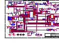
1
SVR-200 Service Manual
SVR-200
Vehicular Repeater
This manual is intended for use by qualified technicians and includes all necessary information pertaining to the
SVR-200 operation, circuit design and maintenance. Changes that occur after date of printing will be
incorporated in supplemental service publications.
Page 1
SVR-200 Service Manual
Foreword
Scope of this manual
This manual contains the specifications, functional description, operating instructions, schematic, parts locator
and parts list for the SVR-200 synthesized vehicular repeater.
This manual is intended for use by qualified service technicians to aid them with installation, interfacing,
alignment and trouble shooting of the SVR-200 when used with other land mobile radios.
Service manual revisions
Component changes, additions and deletions may occur in the circuit design to improve operation and will be
reflected in future releases of this service manual. Specifications and circuit changes are subject to change without
prior notice or obligation by Pyramid Communications.
Safety Information
The SVR-200 is designed to operate within all applicable Federal regulations at the time of manufacture. Proper
operation and service procedures will assure continued compliance with these regulations:
•
Do not operate the SVR-200 without an antenna or appropriate RF load connected to the antenna connector.
•
Do not operate the SVR-200 in the presence of unshielded electrical blasting caps or explosive environmental
conditions.
•
Do not operate the SVR-200 while refueling the vehicle or in the presence of explosive fumes.
•
Do not operate the SVR-200 with persons standing closer than 2 feet from the mobile or repeater antenna.
FCC information
The SVR-200 complies with the FCC rules parts 90 and 22 for radio frequency transmitters. The user must apply
for a license to operate the SVR-200 transmitter pursuant to parts 90.243 and 90.247. Other FCC rules may apply
depending on the class of service the user qualifies for. A complete listing of FCC rules and regulations may be
ordered from:
Superintendent of Documents
Government printing office
Washington DC 20402
The following information pertaining to the SVR-200 should be included in the FCC license application:
Type Acceptance:
Output Power:
Emission designator:
Frequency band:
VHF
UHF
700/800/900 MHz
LRUSVR-200VB
0.25-2.0W
LRUSVR-200U
0.25-2.0W
LRUSVR-200M
100mW-600mW
11K0F3E/16K0F3E
11K0F3E/16K0F3E
11K0F3E/16K0F3E
150-174 MHz
400-512MHz
764-806(700M), 806-824 or 850-870(800M)
897-902 or 936-941 (900M)
1/14
Number of Channels: 1/14
Page 2
1/14
SVR-200 Service Manual
Specifications
Transmitter:
VHF
UHF
700/800/900 MHz
Frequency Range:
150-174 MHz
Rf power out:
Spurious emissions:
Freq stability -30°~+60°C:
Modulation:
Hum and Noise:
Audio response (300-3kHz):
Audio distortion:
Local mic sensitivity:
FCC Type Acceptance:
Industry Canada Approval:
250mW - 2W
-50dBc
1.5 PPM
16K0F3E/11K0F3E
-40/-37dB (25/12.5kHz)
Flat or +6dB/octave
<3% @ 60% deviation
300mV-5VPP
LRUSVR-200VB
2390 195 458A
405-425 MHz (UA)1
450-470 MHz (UD)
470-490 MHz (UE)1
250mW - 2W
-50 dBc
1.5 PPM
16K0F3E/11K0F3E
-40/-37dB (25/12.5kHz)
Flat or +6dB/octave
<3% @ 60% deviation
300mV-5VPP
LRUSVR-200U
2390 212 113A
764-776, 794-806 (MC,MD)
806-824, 850-870 (MB,MA)
897-902, 936-941 (ME,MF)
100mW - 600mW
-50dBc
1.5 PPM
16K0F3E2/11K0F3E
-40/-37dB (25/12.5kHz)
Flat or +6dB/octave
<3% @ 60% deviation
300mV-5VPP
LRUSVR-200M
2390A-SVR200M
764-776, 794-806 (MC,MD)
806-824, 850-870 (MB,MA)
897-902, 936-941 (ME,MF)
.35μV
.2μV to 2μV adjustable
±7.52 /±3.75kHz
50dB
60db
60db
1.5 PPM
Flat or -6db/octave
0-5VPP AC coupled
400 mW 8 Ohms
13.6VDC
170mA
250mA
700mA @ 600mW
Receiver:
Frequency Range:
150-174 MHz
RF sensitivity:
Squelch sensitivity:
Modulation acceptance:
Selectivity:
Spurious/image rejection:
IMD response:
Frequency stability:
Audio response (300-3kHz):
Audio output:
Local Rx Audio:
.35μV
.2μV to 2μV adjustable
±7.5/±3.75kHz
60/57dB (25/12.5 kHz)
60db
60db
1.5 PPM
Flat or -6db/octave
0-5VPP AC coupled
400 mW 8 Ohms
405-425 MHz (UA)1
450-470 MHz (UD)
470-490 MHz (UE)1
.35μV
.2μV to 2μV adjustable
±7.5/±3.75kHz
60/57dB (25/12.5 kHz)
60db
60db
1.5 PPM
Flat or -6db/octave
0-5VPP AC coupled
400 mW 8 Ohms
13.6 VDC
170 mA
250 mA
1 A @ 2W
13.6VDC
170mA
250mA
1.5A @ 2W
Power Requirements:
DC Supply
Standby
Receive
Transmit
Physical:
Dimensions:
Weight:
Case:
1
2
5.275"W x 6"L x 1.12"H
18 oz.
One piece extruded aluminium
405-425 and 470-490 available as special order Only
16K0F3E & ±7.5kHz available on 806-824 and 850-870 MHz Only
Page 3
SVR-200 Service Manual
Functional Description
Generally, vehicular repeaters are used as mobile extenders in cross-band operation: the link is VHF/UHF/800
MHz simplex and the mobile is Lo-band, VHF, UHF or trunking. In-band operation is possible, but care must be
taken to prevent interference between the mobile's higher power transmitter and the repeater receiver. Proper
frequency selection and antenna placement are important even in cross-band operation, but especially for inband
use. The use of low power pre-selector cavities may be placed in line with the repeater antenna cable since it is
simplex and low power.
Important Note
The SVR-200 operates on simplex frequencies; part of the multi-vehicle format dictates that all of the
SVR-200s must be able to monitor all link traffic on site and be able to determine if a handheld is transmitting, or
if other repeaters are transmitting. The handhelds must transmit CTCSS, but should be carrier squelch receive.
The handhelds should not use CTCSS decode if the repeater is utilizing the multi-vehicle format, as this will
interfere with the priority sampling which is essential for multi-vehicle operation. Also, the handhelds would have
to have different encode and decode tones in order for the repeater to be able to tell the difference between
handhelds and other repeaters, so the handhelds would not be able to hear each other. The repeaters should not
transmit CTCSS unless used only in a single vehicle environment.
When the user leaves the vehicle, they activate the SVR-200 via their mobile radio front panel or a separate
switch. When the mobile radio is receiving carrier and proper tone, the SVR-200 will begin transmitting on the
handheld’s receive frequency. The user is able to hear and respond to all radio traffic, including other handhelds
at the site. The SVR-200 can be programmed to give the handhelds priority in a conversation by periodically
sampling for handheld activity (carrier and proper tone) during base-to-portable transmissions. During sampling,
if the SVR-200 detects a handheld transmission, it will cease transmissions, key the mobile radio and repeat
portable-to-base. This allows the handheld to respond during repeater hang time or during full duplex interconnect
calls. Priority sampling can be enabled/disabled through PC programming and the interval can be programmed
between .25 seconds and 2.5 seconds in .25 second increments.
The SVR-200 has a fixed 3 minute time out timer for base-to-portable transmissions. If the mobile COR is
active for more than 3 minutes (and the SVR-200 is the priority unit) it will send a double blip and cease transmission
until the mobile COR is inactive. The 3 minute time-out is in affect regardless of whether the SVR-200 is
programmed for priority sampling or not.
Multi-vehicle operation
When the SVR-200 is first activated, it will transmit a short “lock tone” that alerts the user that the system is
functioning. It will then assume the priority status and be ready to repeat any base-to-portable or portable-to-base
transmissions. If another unit arrives on scene and is activated, it too will transmit the “lock tone”; when the first
SVR-200 detects the lock tone from the second unit, it will increment a “priority counter” and will no longer repeat
any transmissions. The recently arrived unit will be the priority repeater, and the first unit will be 1 count away from
priority. This process will continue for each unit that arrives at the site, creating a priority hierarchy for up to 256
vehicles, each with a unique count and only one unit at priority status. The SVR-200 will not transmit it’s lock tone
if the radio channel is busy when first enabled. It will wait in non-priority status until all transmissions cease, then
send its lock tone and become the priority unit.
Even though the other SVR-200s are not at priority status, they will continue to monitor the channel for activity.
If the priority unit were to leave the scene or become disabled, the other units will detect the condition to repeat
and determine that there is no priority unit repeating the transmission. They will then begin to decrement their
priority counters until one of them reaches the priority status and begins repeating the transmission. Since the
SVR-200s are all at different counts, only one will reach priority status and begin transmitting. The other units will
sense the new priority repeater and cease counting down, preserving the priority hierarchy.
Page 4
SVR-200 Service Manual
If another unit were to arrive from a different scene and it is still the active priority, there will be two active
repeaters on the air when a condition to repeat exists. When one of the SVR-200s unkeys to check for handheld
activity, it will detect the presence of the other active SVR-200 and increment it’s priority counter and cease
transmission. This is the self clearing mode to prevent radio collisions.
If the handheld operator is out of the vehicle and their partner still in the vehicle were to key the mobile radio
using the local mic, the SVR-200 will detect the local PTT and repeat the transmission to the other handhelds so
that both sides of the conversation will be heard by everyone on the link. The local mic repeat function can be
enabled/disabled via the PC software.
The SVR-200 also has a local receive audio speaker jack that enables the person in the vehicle to monitor
portable-to-base transmissions that are being repeated through the mobile.
If the users wish to communicate portable-to-portable without accessing the mobile repeater, they may transmit
on the same frequency without CTCSS (or a different CTCSS); the SVR-200 only responds to carrier and proper
tone from the handhelds.
Trunking operation
When the SVR-200 is connected to a trunking mobile and the handheld operator wishes to access the system,
they key their handheld briefly then release. The SVR-200 will attempt to acquire a voice channel on the trunking
system by keying the mobile for 200mS and monitoring the on-air detect line from the mobile. If it does not see
the radio transmit at all (system is busy), it will send a low tone to the hand held operator to alert them that the system
is busy. The SVR-200 will automatically retry every 5 seconds and send busy tone to the handheld with each
unsuccessful attempt to indicate progress of the call attempt. If unsuccessful after 30 seconds, the SVR-200 will
transmit intercept tone to alert the handheld operator that the call attempt failed.
When the SVR-200 detects that the mobile is transmitting, it will continue to monitor the on-air line until the
transmitter remains keyed for at least 250mS to ensure that the radio is merely handshaking or retrying. After
successful acquisition of a voice channel, it will continue to hold the mobile PTT active for 2 seconds and transmit
a go-ahead blip to the handheld operator. The user then keys their handheld to speak on the voice channel. If the
user does not key up within the 2 second period, the SVR-200 will unkey the mobile and send intercept tone as
before.
If the user keys their handheld only once, or they key the first time for more than 1 second, the SVR-200 will
cancel the call attempt and send intercept tone to the handheld operator. All of the queuing and error tones will only
be sent if the handheld is not transmitting to ensure that the user hears the proper tones.
LEDs
CPU:
PRI:
RCOR:
RTONE:
RTX:
MCOR:
MTX:
OPT:
Flashes at a 1 Hz rate to indicate proper operation of the microprocessor.
When on, indicates that the unit is at priority count zero and will repeat all transmissions.
Repeater Carrier detect.
Repeater sub-audible decode; when on, indicates a condition to repeat portable-to-base.
Repeater transmit indicator.
Mobile unmute detector indicating a condition to repeat base-to-portable.
Mobile transmit indicator.
Should be on steady during programming operations only. If OPT LED flashes at 10Hz rate, it is an
indication that the PLL did not lock within the allotted 50mS and the unit should be serviced.
Page 5
SVR-200 Service Manual
Installation
Before installing the SVR-200, ensure that the RF and repeater sections are properly aligned per the tuning
instructions on pages 8-14 of this manual. Additionally, ensure that the SVR-200 jumpers are properly configured
for use with the particular mobile radio that it will be connected to:
J1 Controls the maximum drive level of the transmit audio output to the mobile radio. If J1 is installed, output amp
U1B will have an adjustment range of 0-100 mVPP. If J1 is removed, U1B can be adjusted between 0-5VPP.
J2 Controls the output impedance of the transmit audio line to the mobile radio. If connected to a low impedance
point in the mobile, installing JP2 sets the output impedance to 600 ohms. If JP2 is open, the output impedance
is 2.2Kohms. Install the jumper for radios that require a lot of modulation drive or that have low impedance
microphone circuits. Remove the jumper if the SVR-200 installation decreases local microphone audio at the
mobile.
J3 Used for testing the SVR-200 receiver and setting the lock tone deviation transmit level. If JP3 is shorted at
power up, the SVR-200 receiver will be active all of the time and receiver audio will be heard at the speaker
regardless of the repeater squelch setting or CTCSS tone decoded. Remove the jumper and turn the SVR-200
off to return to normal operation. If JP3 is shorted while power is applied, the SVR-200 will go into transmit
mode and send lock tone for as long as the jumper is shorted. Remove the jumper to return to normal operation.
J4 Used to internally tie the local mic input of the SVR-200 to the transmit audio output line which is usually
connected to the mic hi line in the mobile.
J5 Used to internally tie the on-air detect input of the SVR-200 to the PTT output. Do so only on conventional
radios; trunking radios must have the on-air detect line connected to a line indicating that the radio is
transmitting.
J6 Changes the maximum gain of the local mic input amp from unity (Out) to 10x (In).
J7 Changes the maximum gain of the receive audio line input from unity (Out) to 7x (In).
J8 Adds a pull up (+ position) or pull down (- position) resistor to the remote enable line (blue).
J9 Adds a pull up resistor (10K to 5VDC) to mobile COR line (violet)
J11 Removing J11 adds 100K ohm resistor in series with SVR-200 mobile transmit audio path. Used for situations
where mobile radio has noise on transmit audio.
J12 Enables external speaker circuit.
Make the connections between the mobile radio and the SVR-200 cable as follows:
Pin 1:
Ground. Connect to the radio's chassis or ground plane.
Black/Shield
Pin 2:
White
Page 6
Mobile transmit audio. Connect to the mobile transmit audio path or tone input. If connected before
pre-emphasis, ensure that the SVR-200 is programmed for de-emphasis (common data). If connected
after pre-emphasis, ensure that the SVR-200 transmit audio path is programmed as flat. Pin 2 is AC
coupled and has an output impedance of 600 or 2.2Kohms (determined by J2). RV3 sets the transmit
audio output level and J1 sets the adjustment range between 0-5VPP (J1 open) or 0-100mVPP (J1
shorted).
SVR-200 Service Manual
Pin 3:
Blue
Pin 4:
Green
Pin 5:
Red
Pin 6:
Yellow
Pin 7:
Violet
Pin 8:
Brown
Pin 9:
Gray
Remote enable/disable. Connect to the radio's auxiliary output or a separate switch to remotely enable
or disable the repeater. If this line goes high to activate the repeater, ensure that JP1 is set to the “+”
position. If this line goes to ground, set JP1 to the “-” position. J8 has two positions to add a pull up
(+) or pull down (-) resistor to this line if used with an open collector or dry contact output.
Mobile PTT output. Connect to mic PTT on the mobile radio, or a line that goes active low to transmit.
Pin 4 is an open collector output rated at 100mA at 50VDC.
12 VDC input. Connect to the radios 12V switched supply or a point capable of supplying at least 1.5A
of current.
Mobile receive audio. Connect this line to the mobile receive audio path before the volume control.
If pin 6 is connected before de-emphasis, ensure that the SVR-200 receive path is programmed as flat
(common data). If connected after de-emphasis, program the receive path for pre-emphasis. Pin 6
is AC coupled and high impedance (>15K ohm). RV5 sets the receive audio level sensitivity; this input
should be between 30mVPP and 5VPP. J7 sets the gain of the receive input amp. If open, the input
has a maximum gain of one; if installed, the input has a maximum gain of 7.
Mobile COR detect. This line is used to indicate when the SVR-200 should repeat the transmission
to the handheld. Connect to a logic point in the radio that indicates proper tone and carrier have been
detected or the audio unmute line. If this line goes more positive during an unmute condition, program
the mobile COR line as active high (common data). If the line goes more negative during an unmute
condition, program the mobile COR line as active low. The input from pin 7 is high impedance and does
not have to go rail to rail. The SVR-200 uses a voltage comparator as a COR threshold detector. RV1
sets the mobile COR threshold level and should be set for half way between the mute and unmute levels
at pin 7. Example: If Pin 7 is connected to a point that goes from 0VDC (mute) to 5VDC (unmute),
set RV1 for 2.5VDC and program the mobile COR line as active high. If Pin 7 goes between 7.2VDC
(mute) and 5.8VDC (unmute), set RV1 for 6.5VDC and program the mobile COR line as active low.
Local mic audio. If programmed for local mic repeat, the SVR-200 will go into transmit mode and
repeat the audio from this line whenever the mobile radio is keyed by the local mic. Connect this line
to the mobile transmitter audio path before limiting or filtering. This input is AC coupled and high
impedance (>5.6Kohms). The input level at this pin should be 300mV to 5VPP. RV2 sets the local
mic sensitivity. If the mic high line has sufficient drive for this input, install J4 and leave pin 8
unconnected. J6 sets the gain of the local mic input amp. If open, the maximum gain is one; if installed,
the maximum gain is 10.
On-Air detect.
Trunking: Connect to a point in the radio that indicates the mobile transmitter is actually on the air.
This is not the same as mic PTT. If pin 9 goes positive during transmit, program the on-air detect line
for active high (common data). If pin 9 goes to ground during transmit, program the on air detect line
for active low.
Conventional: Used for local mic repeat indication from the mobile. Connect pin 9 to pin 4 of the
SVR-200 and program the on-air detect line for active low. Solder jumper J5 will connect pin 9 to pin
4 (PTT output) and can be used on conventional systems only. Do not install J5 for trunking
operation.
Install the SVR-200 in the vehicle using the supplied mounting bracket and hardware. Install the unit where
it will be easily visible by the driver and will not interfere with the drivers vision or constitute a hazard during a vehicle
collision. The SVR-200 mounts in the bracket using the four 8-32 x ¼" machine screws. Do not use longer screws
to mount the SVR-200 to the bracket or circuit damage may result.
Page 7
SVR-200 Service Manual
Alignment VHF
Before aligning the SVR-200, ensure that the mobile radio is aligned per the manufacturer’s service procedure;
Ensure that the SVR-200 is properly programmed and the jumpers are set per the previous section.
In order to properly align the SVR-200, you will need two service monitors and the mobile radio that the repeater
will be installed with. Refer to figure 1 for alignment points.
Dis-assemble the repeater by removing the two cap screws on the rear panel and the phillips screw on the
bottom. Slide the main circuit board out of the housing with the rear panel attached. Connect one service monitor
to the SVR-200 TNC jack and the other to the mobile antenna jack. Connect the cable from the mobile radio to
the SVR-200 (See figure 4 on page 14). Turn on the mobile and activate the SVR-200.
Adjust the repeater squelch control (RV9) so that the repeater COR led is off. Adjust the mobile so that the audio
is squelched.
SVR-200 VHF Transmitter
1. Transmitter Output: Short J3 and adjust RV10 for maximum. Confirm the SVR-200 RF Power out is at least
2W. Adjust RV10 for 250 mW. The SVR-200 case is integral to the voltage regulator heat sink and the unit
should not transmit at full power when removed from the case for extended periods.
2. Transmitter frequency: Adjust the TCXO on the RF board for the transmit frequency.
3. Maximum deviation/lock tone deviation: Adjust RV7 (lock tone deviation) for maximum. If the SVR-200
is programmed for sub-audible encode, adjust RV6 (CTCSS) for minimum. Adjust RV8 (repeater deviation)
for 95% deviation. Adjust RV7 for 60% deviation. Remove J3.
4. Mobile COR: Measure the voltage at TP2 on the SVR-200 main PCB and record. Set the mobile service
monitor for the mobile receive frequency, 1mV RF output and CTCSS modulation of 15% deviation. Measure
the voltage again at TP2 and record. Turn the mobile service monitor off and adjust RV1 on the SVR-200 main
board for the halfway point between the two voltage readings as read at pin 3 of U1.
5. RX audio sensitivity/CTCSS deviation: Set the service monitor connected to the mobile for the mobile receive
frequency and 1mV RF output. Modulate the signal generator with a 1kHz tone at 60% deviation and CTCSS
tone at 15% deviation. Ensure that the SVR-200 mobile COR and repeater PTT LED’s are on. Adjust RV5
on the SVR-200 main board for 60% deviation as read on the service monitor connected to the SVR-200. If
programmed for sub-audible encode, remove the 1kHz tone deviation from the mobile service monitor and
adjust RV6 on the SVR-200 main board for 15% deviation. Turn the RF output from the mobile service monitor
off and ensure that the SVR-200 mobile COR and repeater PTT LEDs are off.
6. Local mic repeat: If the SVR-200 is programmed for local mic repeat, key the mobile local mic and inject an
audio signal into the local mic to produce 60% deviation on the service monitor connected to the mobile.
Confirm that the SVR-200 repeater PTT LED is on; adjust RV2 for 60% deviation as read on the service
monitor connected to the SVR-200. Unkey the mobile radio.
7. RF power out: Short J3 and adjust RV10 for the operating power output. Open J3.
Page 8
SVR-200 Service Manual
VHF Receiver
1. Receiver front end: Connect a DC voltmeter to TP1 on the SVR-200 main board. Set the service monitor
connected to the SVR-200 to the generate mode, receive frequency with a 1kHz tone and 60% deviation.
Adjust the RF output of the monitor for a 1VDC reading at TP1. Adjust L1-L5 on the RF board for a maximum
reading at TP1.
2. Repeater squelch: Adjust the service monitor RF output for .5μV. Adjust RV9 on the SVR-200 main board
so the repeater COR LED is just on. Decrease the service monitor RF output to .3μV and ensure that the
repeater COR LED is off.
3. Transmit audio output: Adjust the service monitor RF output for 1mV. Turn the CTCSS modulation on and
set for 15% deviation. Confirm that the repeater COR, CTCSS and mobile PTT LED’s are on. Adjust RV3
on the SVR-200 main board for 60% deviation as read on the service monitor connected to the mobile radio.
4. Local Rx audio: Connect an 8 ohm speaker to P4 and set RV4 for the desired listening level. Turn off the
CTCSS modulation of the service monitor connected to the SVR-200. Confirm that the repeater CTCSS and
mobile PTT LED’s are off.
5. Lock Tone Decode: Change the 1kHz tone modulation to the lock tone frequency. Confirm that the PRI LED
goes off after approximately .5 seconds.
TP2
Figure 1
Page 9
SVR-200 Service Manual
Alignment UHF
Before aligning the SVR-200, ensure that the mobile radio is aligned per the manufacturer’s service procedure;
Ensure that the SVR-200 is properly programmed and the jumpers are set per the previous section.
In order to properly align the SVR-200, you will need two service monitors and the mobile radio that the repeater
will be installed with. Refer to figure 2 for alignment points.
Dis-assemble the repeater by removing the two cap screws on the rear panel and the phillips screw on the
bottom. Slide the main circuit board out of the housing with the rear panel attached. Connect one service monitor
to the SVR-200 TNC jack and the other to the mobile antenna jack. Connect the cable from the mobile radio to
the SVR-200 (See figure 4 on page 14). Turn on the mobile and activate the SVR-200.
Adjust the repeater squelch control (RV9) so that the repeater COR led is off. Adjust the mobile so that the audio
is squelched.
SVR-200 UHF Transmitter
1. Transmitter Output: Short J3 and adjust RV10 for maximum. Confirm the SVR-200 RF Power out is at least
2W . Adjust RV10 for 250 mW. The SVR-200 case is integral to the voltage regulator heat sink and the unit
should not transmit at full power when removed from the case for extended periods.
2. Transmitter frequency: Adjust the TCXO on the RF board for the transmit frequency.
3. Maximum deviation/lock tone deviation: Adjust RV7 (lock tone deviation) for maximum. If the SVR-200
is programmed for sub-audible encode, adjust RV6 (CTCSS) for minimum. Adjust RV8 (repeater deviation)
for 95% deviation. Adjust RV7 for 60% deviation. Remove J3.
4. Mobile COR: Measure the voltage at TP2 on the SVR-200 main PCB and record. Set the mobile service
monitor for the mobile receive frequency, 1mV RF output and CTCSS modulation of 15%. Measure the voltage
again at TP2 and record. Turn the mobile service monitor off and adjust RV1 on the SVR-200 main board for
the halfway point between the two voltage readings as read at pin 3 of U1.
5. RX audio sensitivity/CTCSS deviation: Set the service monitor connected to the mobile for the mobile receive
frequency and 1mV RF output. Modulate the signal generator with a 1kHz tone at 60% deviation and CTCSS
tone at 15% deviation. Ensure that the SVR-200 mobile COR and repeater PTT LED’s are on. Adjust RV5
on the SVR-200 main board for 60% deviation as read on the service monitor connected to the SVR-200. If
programmed for sub-audible encode, remove the 1kHz tone deviation from the mobile service monitor and
adjust RV6 on the SVR-200 main board for 15% deviation. Turn the RF output from the mobile service monitor
off and ensure that the SVR-200 mobile COR and repeater PTT LEDs are off.
6. Local mic repeat: If the SVR-200 is programmed for local mic repeat, key the mobile local mic and inject an
audio signal into the local mic to produce 60% deviation on the service monitor connected to the mobile.
Confirm that the SVR-200 repeater PTT LED is on; adjust RV2 for 60% deviation as read on the service
monitor connected to the SVR-200. Unkey the mobile radio.
7. RF power out: Short J3 and adjust RV10 for the operating power output. Open J3.
Page 10
SVR-200 Service Manual
UHF Receiver
1. Receiver front end: Connect a DC voltmeter to TP1 on the SVR-200 main board. Set the service monitor
connected to the SVR-200 to the generate mode, receive frequency with a 1kHz tone and 60% deviation.
Adjust the RF output of the monitor for a 1VDC reading at TP1. Adjust BPF1 and BPF2 on the RF board for
a maximum reading at TP1.
2. Repeater squelch: Adjust the service monitor RF output for .5μV. Adjust RV9 on the SVR-200 main board
so the repeater COR LED is just on. Decrease the service monitor RF output to .35μV and ensure that the
repeater COR LED is off.
3. Transmit audio output: Adjust the service monitor RF output for 1mV. Turn the CTCSS modulation on and
set for 15% deviation. Confirm that the repeater COR, CTCSS and mobile PTT LED’s are on. Adjust RV3
on the SVR-200 main board for 60% deviation as read on the service monitor connected to the mobile radio.
4. Local Rx audio: Connect an 8 ohm speaker to P4 and set RV4 for the desired listening level. Turn off the
CTCSS modulation of the service monitor connected to the SVR-200. Confirm that the repeater CTCSS and
mobile PTT LED’s are off.
5. Lock Tone Decode: Change the 1kHz tone modulation to the lock tone frequency. Confirm that the PRI LED
goes off after approximately .5 seconds.
TP2
Figure 2
Page 11
SVR-200 Service Manual
Alignment 700/800/900 MHz
Before aligning the SVR-200, ensure that the mobile radio is aligned per the manufacturer’s service procedure;
Ensure that the SVR-200 is properly programmed and the jumpers are set per the previous section.
In order to properly align the SVR-200, you will need two service monitors and the mobile radio that the repeater
will be installed with. Refer to figure 3 for alignment points.
Dis-assemble the repeater by removing the two cap screws on the rear panel and the phillips screw on the
bottom. Slide the main circuit board out of the housing with the rear panel attached. Connect one service monitor
to the SVR-200 TNC jack and the other to the mobile antenna jack. Connect the cable from the mobile radio to
the SVR-200 (See figure 4 on page 14). Turn on the mobile and activate the SVR-200.
Adjust the repeater squelch control (RV9) so that the repeater COR led is off. Adjust the mobile so that the audio
is squelched.
SVR-200 700/800/900 MHz Transmitter
1. Transmitter Output: Short J3 and adjust RV10 for maximum. Confirm the power out is at least 600mW.
Adjust RV10 for 100 mW. The SVR-200 case is integral to the voltage regulator heat sink and the unit should
not transmit at full power when removed from the case for extended periods.
2. Transmitter frequency: Adjust the TCXO on the RF board for the transmit frequency ±100 Hz.
3. Maximum deviation/lock tone deviation: Adjust RV7 (lock tone deviation) for maximum. If the SVR-200
is programmed for sub-audible encode, adjust RV6 (CTCSS) for minimum. Adjust RV8 (repeater deviation)
for 95% deviation. Adjust RV7 for 60% deviation. Remove J3.
4. Mobile COR: Measure the voltage at TP2 on the SVR-200 main PCB and record. Set the mobile service
monitor for the mobile receive frequency, 1mV RF output and CTCSS modulation of 15%. Measure the voltage
again at TP2 and record. Turn the mobile service monitor off and adjust RV1 on the SVR-200 main board for
the halfway point between the two voltage readings as read at pin 3 of U1.
5. RX audio sensitivity/CTCSS deviation: Set the service monitor connected to the mobile for the mobile receive
frequency and 1mV RF output. Modulate the signal generator with a 1kHz tone at 60% deviation and CTCSS
tone at 15% deviation. Ensure that the SVR-200 mobile COR and repeater PTT LED’s are on. Adjust RV5
on the SVR-200 main board for 60% deviation as read on the service monitor connected to the SVR-200. If
programmed for sub-audible encode, remove the 1kHz tone deviation from the mobile service monitor and
adjust RV6 on the SVR-200 main board for 15% deviation. Turn the RF output from the mobile service monitor
off and ensure that the SVR-200 mobile COR and repeater PTT LEDs are off.
6. Local mic repeat: If the SVR-200 is programmed for local mic repeat, key the mobile local mic and inject an
audio signal into the local mic to produce 60% deviation on the service monitor connected to the mobile.
Confirm that the SVR-200 repeater PTT LED is on; adjust RV2 for 60% deviation as read on the service
monitor connected to the SVR-200. Unkey the mobile radio.
7. RF power out: Short J3 and adjust RV10 for the operating power output. Open J3.
Page 12
SVR-200 Service Manual
700/800/900 MHz Receiver
1. Receiver front end: Connect a DC voltmeter to TP1 on the SVR-200 main board. Set the service monitor
connected to the SVR-200 to the generate mode, receive frequency at .5μV RF output with a 1kHz tone and
60% deviation. Confirm a reading of 1VDC ±.2VDC at TP1.
2. Repeater squelch: Adjust the service monitor RF output for .5μV. Adjust RV9 on the SVR-200 main board
so the repeater COR LED is just on. Decrease the service monitor RF output to .25μV and ensure that the
repeater COR LED is off.
3. Transmit audio output: Adjust the service monitor RF output for 1mV. Turn the CTCSS modulation on and
set for 15% deviation. Confirm that the repeater COR, CTCSS and mobile PTT LED’s are on. Adjust RV3
on the SVR-200 main board for 60% deviation as read on the service monitor connected to the mobile radio.
4. Local Rx audio: Connect an 8 ohm speaker to P4 and set RV4 for the desired listening level. Turn off the
CTCSS modulation of the service monitor connected to the SVR-200. Confirm that the repeater CTCSS and
mobile PTT LED’s are off.
5. Lock Tone Decode: Change the 1kHz tone modulation to the lock tone frequency. Confirm that the PRI LED
goes off after approximately .5 seconds.
TP2
Figure 3
Page 13
SVR-200 Service Manual
Communications
Monitor A
Mobile Radio
Communications
Monitor B
Interface
Cable
SVR-200
Figure 4
Page 14
SVR-200 Service Manual
Programming
Using the Software
The SVRCPS personalization software is used to program the SVR-200 for all of the operating parameters
and options. The software is compatible with Windows 2000 and later operating systems The software is menu
driven and on-line help is available at any time by clicking the left mouse button on the HELP icon on the right side
of the tool bar.
Important Note:
Before attempting to program the SVR-200 start the software and ensure the FY-1 programming cable is
plugged into the correct serial port. The com port may be selected under the “Transfer” menu. Plug the FY-1
programming cable into P3 on the front of the SVR-200; the OPT LED on the SVR-200 front panel should be on
continuously:
Menu selections
File
Open: Allows you to load a previously saved file from disk. Enter the file name or select from the Windows Dialog
box. Only files with the .VR2 extension can be loaded.
Save: Allows you to save the current configuration to disk. Enter the file name to save as or select a previous file
from the Windows Dialog box to overwrite. The .VR2 extension is automatically added to the file name. The
program will prompt you before overwriting an existing file.
Print: Sends the current configuration to the selected printer. Make sure the printer is on line and paper is loaded
before executing this command.
Exit: You will be asked to confirm before exiting the program. The software will also prompt you if the
configuration has changed since program start up and data has not been saved to disk.
Data
Frequencies: Enter the transmit and receive frequencies and select the encode and decode sub-audio data. The
program will automatically round off the frequencies to the nearest channel step if incorrect data is entered. To
enter VHF offset frequencies (6.25kHz channel steps), go to common data and select the "VHF Offset" band.
To disable sub-audio encode operation, select "------"; sub-audio decode cannot be disabled.
Common data: Controls all of the options and input polarities of the SVR-200. Make sure all of the settings are
correct for the type of mobile radio the repeater is connected to or improper operation may result.
File name: This data is stored in the E²PROM of the SVR-200 during downloads.
Model: Select either SVR-200 (single frequency) or SVR-214 (14 channel).
Band: Select the proper frequency band to correspond with the model SVR-200 you are programming. This
selection is automatically set by reading the SVR-200. The IF frequency, injection side and channel step are
displayed next to the band selection. Select VHF Offset band for 6.25kHz channel steps.
Page 15
SVR-200 Service Manual
Mobile COR polarity: Determines if the COR signal from the mobile is active high or active low.
Radio Type: Select either conventional or trunking. If a trunking mobile is selected, the SVR-200 will go through
the voice channel acquisition procedure during portable-to-base repeat mode.
On-air polarity: Select either active high or active low. This line is used to monitor the local mobile PTT for local
mic repeat on conventional radios. On trunking radios, it is also used to determine if the mobile is actually
transmitting.
TX Audio: If the mobile transmit audio output from the SVR-200 is connected after pre-emphasis in the mobile,
select Flat response. If connected before pre-emphasis or to the mic input, select De-Emp.
RX Audio: If the receive audio coming from the mobile is connected to the discriminator or before de-emphasis,
select Flat response. If connected after de-emphasis, select Pre-Emp.
Lock Tone: Select either 682.5, 832.5 or 847.5 Hz. All units in the system must have the same lock tone frequency.
Local mic repeat: Enables or disables the local mic repeat function; if enabled, ensure that the on-air polarity input
is correctly configured.
Courtesy Blip: (Firmware version 3.02 & above) Enables or disables the courtesy tone at the end of each
portable-to-base transmission. The tone verifies the handheld is within range of the repeater and transmission was
successful. It also serves to notify other handheld users that the channel is clear for use.
Pri-sampling: Enables or disables the pri-sampling feature of the SVR-200. If used in multi-vehicle
applications, this must be enabled for proper operation. During base-to-portable repeat mode, the SVR-200
transmitter will switch to receive mode to check for other repeaters or handheld activity. If another repeater is
detected (carrier without/wrong tone) the repeater will cease activity to prevent radio “collisions”. If handheld
activity is detected (carrier & correct tone) the SVR-200 will switch to portable-to-base repeat mode.
Sampling rate: If pri-sampling is enabled, this selects the sampling interval. The range is 0.25 seconds to 2.5
seconds in .25 second increments. The higher this setting, the longer the handheld operator must wait before
speaking after pressing PTT during base-to-portable repeat mode, since the repeater may still be in transmit mode
(there is no delay if the repeater is idle). If the interval is too short, some users may complain about the “chop”
that is heard in the handhelds.
Transfer
Send: Downloads the current configuration to the repeater. The program will prompt you to make the FY-1
connection before downloading. Download takes approximately 5 seconds.
Receive: Uploads the current data from the repeater. The program will prompt you to make the FY-1 connection
before uploading. Upload takes approximately 4 seconds.
Comm Port: Selects the serial port to use for uploading and downloading between the PC and the SVR-200. Comm
ports 1-4 are supported.
Help
Help is available at any time by clicking the left mouse button on the HELP icon on the right side of the tool
bar. The help is context sensitive and will depend upon where the cursor is located on particular menu displayed.
Page 16
SVR-200 Service Manual
Receiver:
Theory of Operation
The receiver is a double-conversion superheterodyne type, designed for narrow band FM reception. The first
local oscillator is derived from the frequency synthesizer. The second LO is crystal controlled.
RF Stage: The incoming RF signal from the antenna jack is directed to the first RF bandpass filter to improve
selectivity and then to the input of the RF amplifier. The output of the RF amplifier is then presented to a second
bandpass filter.
First LO/Mixer: The first LO signal is developed by the synthesizer and is mixed with the incoming signal to
produce the first IF frequency (45 MHz). The IF frequency is filtered by FL1A and FL1B and amplified by the
IF amplifier before being presented to the second LO/Mixer IC.
Second LO/Mixer: The first I.F. signal is presented to the second IF IC (MC3371) which performs the functions
of second LO, second I.F. amp and mixer, FM discriminator and squelch. The second LO crystal (44.545 MHz)
is mixed with the 45 MHz first I.F. signal to produce the second I.F. frequency of 455 kHz. A 6 pole ceramic filter
provides selectivity for the 455 kHz signal.
Detector/Squelch: The MC3371 demodulates the 455 kHz signal via quadrature coil to produce the audio and noise
components. The output of the MC3371 is the recovered audio and the RSSI voltage (receiver signal strength
indicator) which is compared by the controller board with a threshold voltage level for squelch setting.
VHF Transmitter
The output of VCO buffer U8 is input to the predriver transistor U7. The output of U7 drives the RF driver
Q8. The collector of Q8 is fed by the transmit 9V line from Q10. The final amp Q13 is a class C power amplifier
and drives the output lowpass and harmonic filter, C47-C50 and L20-L22. D3 is the transmit output switch and
L19 is a ¼ wave transmission line to isolate the receiver switching diode D2. RF output power is controlled by
changing the bias on the gate of Q13 via the TX 9V line (pin 3) from the controller PCB.
UHF Transmitter
The output of VCO buffer U6 is input to the predriver transistor U5. The output of U5 drives the RF driver
transistor Q4. The collector of Q4 is fed by the transmit 9V line from Q5. The final amp Q3 is a class C power
amplifier and drives the output lowpass and harmonic filter, C39-C42 and L26-L28. D3 is the transmit output switch
and L14 is a ¼ wave transmission line to isolate the receiver switching diode D2. RF output power is controlled
by changing the bias on the gate of Q3 via the TX 9V line (pin 3) from the controller PCB.
700/800/900 MHz Transmitter
The output of the transmit VCO is buffered by U5 input to the driver transistor U1. The output of U1 drives
the RF hybrid output amp U4 through lowpass filter FL3. The final amp U4 is a class C power amplifier and drives
the output lowpass and harmonic filter FL4. U7 is the Tx/Rx antenna switch. RF output power is controlled by
changing the voltage on pin 1 of U4 via the TX 9V line (pin 3) from the controller PCB.
Control Board
Power Supply: DC power comes from the mobile radio via P1 pins 1 and 5. Fuse F1 and MOV VAR1 provide
over current and voltage spike protection. Q3 is the remote enable/disable pass switch, controlled by Q1 and Q2
via P1 pin 3. Q3 output is switched 12VDC and is presented to audio amp U6, and voltage regulators U7 and U8.
Bias voltage for the op-amp circuits is provided by voltage divider R68, R69 and buffer amp U2A.
Transmit audio path: Receiver audio from the mobile is input to the mic amp portion of U4; PC programming of
the SVR-200 provides flat response or +6db/octave pre-emphasis. The output of the mic amp is internally connected
to the limiter and lowpass filter. When a condition to repeat exists (base-to-portable) U4 audio is switched on and
audio is presented to amplifier/limiter and lowpass filter to remove audio components above 3kHz. U4 provides
-48db/octave of attenuation to out of band signals. Transmit audio is output on pin 22 of U4 and passes through
the final lowpass filter U2C to remove any clock noise generated by U4’s switched capacitive filters before being
presented to the RF module on P2 pin 6.
Page 17
SVR-200 Service Manual
Receive audio path: Receiver audio from the transceiver module is input on P2 pin 13 and presented to U5 pin
10 and pin 16. Pin 10 is the input of the receiver highpass filter to remove any sub-audible signals before being output
on pin 11 and sent to U4 for receiver audio processing. Pin 16 is the input to the sub-audible tone decoder section
of U5. Receive audio entering pin 7 of U4 is processed as flat, or -6db/octave depending upon PC programming.
The receive audio then passes through the internal lowpass filters to remove unwanted noise and output on pin 21,
where it is sent to the local receiver audio amp and mobile transmit audio output amp U1B. J1 selects either high
sensitivity (open) or low sensitivity (shorted) and J2 selects the output impedance (600/2.2K Ohms).
Sub-Audible tone signalling: U5 processes the sub-audible signal from the receiver by comparing the incoming
signal to previous samples in a noise correlator. If the signal is sufficiently coherent, the output of the comparator
is counted by the internal circuitry and an interrupt is generated to the main microprocessor. U12 reads the data
from U5 in 2 bytes: byte one contains the number of complete cycles detected within 122mS, and byte 2 contains
the number of internal clock cycles elapsed for the remainder. U12 performs a comparison of minimum and
maximum values allowed in a look up table and determines if the data is within the decode bandwidth for the
programmed tone.
In band tone signalling: Audio from the transceiver is also fed to U3B where it is amplified and limited for input
to the commutating switched capacitive filter made up by C23-C26 and P0.4-P0.7 of the microprocessor. The
microprocessor outputs four identical signals with 90° phase difference on the respective port pins. The resultant
wave form will be a function of the difference between the incoming signal frequency and the decode frequency
output by the microprocessor. The signal is buffered by U3C and amplified by U3A before being rectified and
filtered by D1 and C2. The resulting DC voltage is compared to the reference voltage by U3D. If the incoming
signal is within the decode bandwidth, the output of U3D will be a logic 1 and read by the microprocessor.
Logic and control: U12 is an Atmel 89C52 microprocessor with flash E²PROM memory. The microprocessor
provides all of the logic and control functions for the repeater including mobile/repeater PTT output, local mobile
PTT sense, mobile transmitter activity sense, audio switching, in-band & CTCSS detect, and repeater status
indications via DS4 and DS5 led arrays.
The 89C52 has four 8 bit ports that interface with the rest of the hardware on the controller board; a brief
description of each port follows:
P0.0-0.3
Channel Selector input; used only on SVR-214 version.
P0.4-0.7
These four lines make up the input to the switched capacitive filter network of C23-C26. During
receive mode, the lock tone frequency will be output on each of these lines with a 90° phase difference
between them at any given time. During transmit mode, these lines are in active and open collector.
P1.0-P1.2 LED data is output on P1.0 line every 10mSec. Data is loaded into shift register U9 8 bits at a time
and is clocked by P1.1. P1.2 latches the data into U9 for display.
P1.3
PLL latch enable output to the RF module. During transmit to receive and receive to transmit
transitions, this line is used to latch the serial data into the PLL shift registers. The serial data and clock
lines are shared with U10 (E²PROM) U4 (audio processor) and U5 (sub-audio processor).
P1.4
E²PROM chip enable, active high. Data is output to the E²PROM on P1.6 and clocked by P1.5. Data
is input from the E²PROM on P1.7. P1.4 will go active during read and write operations with U10.
U10 is written to every time the unit is programmed. U10 is read only at power up.
Page 18
SVR-200 Service Manual
P1.5
Serial clock line output. Serial data that is sent to the PLL, the E²PROM and the audio processor chips
are clocked by each low-high-low transition on this line.
P1.6
Serial data output. Data sent to U10, U4 and U5 are output on this line and clocked by P1.5.
P1.7
Data input to the microprocessor. Serial data is read from U10 (E²PROM) and U5 (sub-audio
processor) on this line.
P2.0
Lock tone output. Lock tone encode is generated by this pin at power up and during lock tone test mode.
All of the queuing tones are also generated by this pin for trunking operation.
P2.1
Lock tone decode input, active high. The output of lock tone decoder U3D is input on this line and
checked during receiver activity. If lock tone is detected, the microprocessor increments its priority
counter and ceases activity as priority unit.
P2.2
Repeater Tx enable. This line is used to turn on the TX 9V signal to the RF PCB. The output drives
buffers Q7 and Q6. The output of Q6 switches Q4 on during transmit for TX 9V. RV10 and APC
circuit U13 are used to set the TX 9V level for RF power control.
P2.3
Mobile PTT output, active low. This line is brought low to key the mobile radio during portable-to-base
repeat operations.
P2.4
Mobile COR input. U1A is a threshold detector for the mobile COR input on pin 7 of P1. The output
of U1A is read by the microprocessor on this port to determine if the SVR-200 should repeat base to
portable. Polarity of this input is determined by PC programming.
P2.5
Repeater COR input, active low. RSSI output from the RF module is sent to threshold detector U2D
for comparison with the squelch setting at RV9. R47 and R70 provide hysteresis to prevent chatter.
Repeater COR is used to enable the CTCSS decoder circuitry; the microprocessor will not decode
the signal from U5 unless repeater COR is also active.
P2.6
Chip select output for U4 (audio processor), active low. Serial data is sent to U4 on P1.6 and clocked
by P1.5. These lines are shared by U5, U10 and the PLL; data is ignored by U4 unless the chip select
line is asserted during data write operations.
P2.7
Chip select output for U5 (sub-audio processor), active low. Serial data is sent to U5 on P1.6 and
clocked by P1.5. These lines are shared by U4, U10 and the PLL; data is ignored by U5 unless the
chip select line is asserted during data read and write operations.
INT0
External interrupt #0. This line monitors the PLL lock detector output. The line is active high to indicate
the PLL is functioning on frequency during transmit-receive and receive to transmit changes. The
output will go briefly unlocked, then revert back to a locked condition. If the PLL does not achieve
lock within 50mS, the transmitter will be disabled and the OPT LED will flash rapidly to alert the user
that the unit should be brought in for service.
INT1
External interrupt #1 active low. This line is used by U5 to signal the microprocessor that it has
completed a decode cycle and data can be read. During receiver activity, this line will go active
approximately every 122 mS in the presence of sub-audio signalling. During transmit mode and
receiver activity without sub-audio signalling, this line will be inactive.
Page 19
SVR-200 Service Manual
T0
Test input, active low. Shorting J3 puts the microprocessor into test mode for alignment purposes. If
shorted at power up, the receiver will operate open squelch mode and audio will be heard at the local
speaker port regardless of carrier or tone input to the receiver. Although alignment is normally done
with the RSSI output at TP1, a Sinad reading can be obtained using this mode of the test input. All
other functions of the SVR-200 are disabled in this mode and power will have to be turned off then
on to reset the unit.
If J3 is shorted after power has been applied, the microprocessor will enter the lock tone test mode,
key the repeater and send the programmed lock tone for as long as J3 is shorted. Remove the short
from J3 to return to normal operation.
T1
On-air detect input. The on-air detect line (P1 pin 9) is used to detect local mic PTT from the mobile,
and in trunking mode, this line is used to detect that the mobile transmitter is actually on the air. The
input is buffered by Q10 and the polarity of the signal is determined by PC programming.
WR
Turns the Rx 5V line on or off to the RF PCB.
RD
Detects the version of RF PCB installed (UHF only).
TXD
Transmit data output for programming. Data is sent to the PC on this line at 300 baud, 8 data bits, 1
stop bit and no parity. This line is active only during programming mode.
RXD
Receive data input for programming. Data is received from the PC on this line at 300 baud, 8 data
bits, 1 stop bit and no parity. This line is also used to sense when the programming cable is inserted.
If RXD is grounded, the SVR-200 operates in the normal mode. If this line is high, programming mode
is entered and the OPT LED is on continuously.
Reset
Active high input to reset the microprocessor. U11 provides a 350mSec delayed high signal to this pin
during power up or if the 5V line falls below 4.5VDC.
Xtal
The microprocessor uses a 4.032MHz xtal for all of the timing and program execution clock cycles.
The output of the on board oscillator also drives the xtal input to U5. The output of U5 xtal oscillator
drives the input of U4.
Page 20
SVR-200 Service Manual
Notes
This Page Intentionally left blank
Page 21
SVR-200 Service Manual
Parts List
Reference
Description
Part #
C1,C5,C6,C9,C10,C12,C15,C18,C35,C37 ......................... .1μFd chip capacitor ............................ 1010-03-5104
C2 ..................................................................................... 22μFd 16V tantalum chip capacitor ..... 1610-25-6226
C3,C27 .............................................................................. .047μFd chip capacitor ........................ 1010-03-5473
C7,C8,C13,C41 ................................................................. 220pFd chip capacitor ......................... 1010-03-5221
C11 .................................................................................... .0033μFd chip capacitor ...................... 1010-03-5332
C16 .................................................................................... 1000pFd chip capacitor ....................... 1010-03-5102
C17 .................................................................................... .0022μFd chip capacitor ...................... 1010-03-5222
C19,C20 ............................................................................ 22pFd chip capacitor ........................... 1010-03-5220
C40 .................................................................................... 0.5pFd chip capacitor .......................... 1010-03-5050
C21A,C21B ...................................................................... 6.8μFd tantalum chip capacitor ........... 1610-05-6685
C22,C32,C33,C34 ............................................................. 100μFd elctrolytic cap ......................... 1400-08-7107
C21,C23,C24,C25,C26 ...................................................... 0.47μFd tantalum chip capacitor ......... 1610-04-6474
C28,C29,C36 ..................................................................... 1.0μFd tantalum chip capacitor ........... 1610-04-6105
C14,C30,C38 ..................................................................... 2.2μFd tantalum chip capacitor ........... 1610-04-6225
D1,D2,D3,D6 .................................................................... BAV99 dual diode SOT23 .................. 3110-01-0099
D4,D5 ............................................................................... Schotkey diode SOT23 ........................ 3110-01-0301
DS4/DS5 ........................................................................... 8 position multi-color LED .................. 4003-08-0200
F1 ...................................................................................... 2A SMT Pica fuse .............................. 2610-04-0020
JP1 .................................................................................... 0.1" 3 position vertical header ............. 7300-53-0103
P1 ...................................................................................... DB-9 M right angle PCB .................... 7400-00-0011
P2 ...................................................................................... 0.1" 14 position vertical header ........... 7300-83-0114
P3 ...................................................................................... 2.5mm RA programming jack ............. 7401-02-0250
P4 ...................................................................................... 3.5mm RA speaker jack ..................... 7401-02-0051
Q1,Q2,Q6,Q7,Q9,Q10 ....................................................... 2N4401 NPN transistor SOT23 .......... 3010-01-4401
Q3 ..................................................................................... IRF-9540 P Ch MOSFET TO220 ....... 3300-08-9540
Q4 ..................................................................................... TIP 32 PNP transistor TO220 ............ 3000-08-0032
Q5 ..................................................................................... 2N4403 PNP transistor SOT23 ........... 3010-01-4403
Q8 ..................................................................................... NPN Darlington SOT23 ...................... 3010-01-0038
RV1,RV8,RV9,RV10 ....................................................... 10K 3mm SMT pot ............................. 2030-08-8103
RV2,RV3,RV5,RV7 ......................................................... 100K 3mm SMT pot ........................... 2030-08-8104
RV4 .................................................................................. 20K 3mm SMT pot ............................. 2030-08-8203
RV6 .................................................................................. 200K 3mm SMT pot ........................... 2030-08-8204
R82 .................................................................................... 10 Ohm chip resistor ........................... 2010-03-5100
R10,R23,R41,R52,R76 ...................................................... 10K chip resistor ................................. 2010-03-5103
R8,R11,R16,R21,R22,R24,R26,R30,R35,R44,
R47,R53,R66,R73 ............................................................. 100K chip resistor ............................... 2010-03-5104
R1,R2,R4,R6,R15,R17,R18,R31,R36,R74,R83 .................. 22K chip resistor ................................. 2010-03-5223
R3,R12,R13,R65,R72,R87 ................................................. 2.2K chip resistor ................................ 2010-03-5222
R5,R14,R86 ....................................................................... 820 Ohm chip resistor ......................... 2010-03-5821
R7,R48,R49,R63,R71 ........................................................ 5.6K chip resistor ................................ 2010-03-5562
R9,R81 .............................................................................. 56K chip resistor ................................. 2010-03-5563
R19,R20 ............................................................................ 470K chip resistor ............................... 2010-03-5474
R25,R29,R34,R51 ............................................................. 1.0M chip resistor ................................ 2010-03-5105
R27,R33,R37,R38,R45,R46,R85 ....................................... 33K chip resistor ................................. 2010-03-5333
R32,R70 ............................................................................ 27K chip resistor ................................. 2010-03-5273
R39,R40 ............................................................................ 150K chip resistor ............................... 2010-03-5154
R42 .................................................................................... 330K chip resistor ............................... 2010-03-5334
Page 22
SVR-200 Service Manual
R50,R77-R80 .................................................................... 15K chip resistor ................................. 2010-03-5153
R54-R62,R64 .................................................................... 330 Ohm chip resistor ......................... 2010-03-5331
R68,R69 ............................................................................ 4.7K chip resistor ................................ 2010-03-5472
R43 .................................................................................... 68K chip resistor ................................. 2010-03-5683
R67 .................................................................................... 8.2 Ohm 1W resistor ........................... 2000-10-5829
U1 ..................................................................................... TS922 dual op-amp ............................. 3410-01-0922
U2,U3 ............................................................................... MC3403 quad op-amp ......................... 3410-01-3403
U4 ..................................................................................... MX-806ALH audio processor ............ 3710-02-0806
U5 ..................................................................................... MX-805ALH sub-audio processor ...... 3710-02-0805
U6 ..................................................................................... LM386 audio amp ............................... 3410-01-0386
U7 ..................................................................................... LM7805 1A regulator ........................ 3400-08-7805
U8 ..................................................................................... LM7809CV 1.5A regulator ................. 3400-08-7809
U9 ..................................................................................... CD4094 shift register .......................... 3410-01-4094
U10 ................................................................................... 93C46 1Kbit Serial E²PROM .............. 3610-01-9346
U11 ................................................................................... MCP101-450 reset controller .............. 3410-11-0450
U12 ................................................................................... AT89C52-12JC Microprocessor ......... 3610-02-8952
U13 ................................................................................... LM321 opamp ..................................... 3410-12-0321
X1 ..................................................................................... 4.032 MHz HC18/U ............................ 6000-07-4032
VAR1 ............................................................................... 18V MOV ........................................... 2580-02-0018
Extruded aluminium case .................... 8100-01-5010
Aluminium end panel ........................... 8200-04-5010
ABS Plastic front panel ....................... 8200-03-2502
TNC PCB mount RA connector ......... 7401-02-0007
10ft. radio cable with DB-9F conn. ..... 7500-10-1001
Shorting block for JP1 ......................... 7200-03-0102
TP1, RF Ant connection ..................... 7300-13-0101
Mounting bracket ................................ 9600-05-0001
RF interconnect board ......................... 9100-00-0001
4-40 SS jack screw ............................. 8000-42-4404
8-32 x ¼" SS philips ............................. 8000-24-8324
4-40 x 3/8" SS cap screw .................... 8000-34-4406
4-40 SS nut .......................................... 8000-54-4400
4-40 x ¼" SS philips ............................. 8000-24-4404
2-56 x 3/16" SS philips ......................... 8000-24-2563
4-40 x 3/16" SS philips ......................... 8000-24-4403
2-56 x 1/8" aluminium spacer ............. 8000-65-2562
Aluminium heat sink (U7 & U8) ......... 8400-05-0001
Right Angle heat sink (RF module) ..... 8400-05-0007
Page 23
4/13/2009 09:34:38a f=1.35 N:/EAGLE/Projects/SVR200L/SVR200.BRD
3
Q2
2N4401
J8
Q3
IRF9540
R6
22K
R5
820
JP1
1
2
3
4
5
9 VDC
R7
5K6
J9
cw
RV1
10K
R9
56K
D6
BAV99
3
R14
2
+
C21A
J11
TL2272
SW B+
J2
820
U1A
R8
100K
6U8
R10
RV2
100K
R72
2K2
J4
J12
RV3
100K
cw
U6
LM386
6
R2
22K
Local
Mic
Sens
cw
R84
100K
R13
2K2
10K
5
U1B
TL2272
C6
.1U
R18
cw
R17
Mob
Dev
9 VDC
22K
J6
22K
P5
VCC
D
C
B
A
J5
R15
22K
Q8
C10
.1U
P3
D3
BAV99
R62
Q10
2N4401
C20
22P
S1 J3
TEST
1M
R20
470K
- R80
15K
R21
100K
20
X2
14
15
16
17
18
19
2
3
4
5
6
7
8
9
INT0
INT1
T0
T1
WR
RD
P1.0
P1.1
P1.2
P1.3
P1.4
P1.5
P1.6
P1.7
P0.0
P0.1
P0.2
P0.3
P0.4
P0.5
P0.6
P0.7
43
42
41
40
39
38
37
36
P2.0
P2.1
P2.2
P2.3
P2.4
P2.5
P2.6
P2.7
24
25
26
27
28
29
30
31
PSEN
ALE/P
TXD
RXD
32
33
13
11
RESET
10
100K
J14
R81
56K
C
R54 - R61
330
4
5
6
7
14
13
12
11
Health
Pri
RCOR
RCTCSS
Q1
Q2
Q3
Q4
Q5
Q6
Q7
Q8
STR
D
CLK
OE
CE
SK
DI
DO
1
2
3
15
1
2
3
4
U10
VCC
VCC
3
I
QS
QS
O
R23
10K
5
U3D
MC3403
C2
22U
Bias
R32
27K
6
R33
33K
R26
100K
C9
.1U
C23 - C26 .47U
U4
MX_806
1
2
3
4
5
6
7
8
9
10
11
12
R50
15K
2
J7
VCC
TX_2
24
23
TX_1
RXOUT
MODIN
MXOUT
MXIN
PAOUT
CAL
EXT
PAIN
MIC
22
21
20
19
18
17
16
15
14
13
X1
X2
SCK
DI
CS
VO
RXI
VI
VB
M+
MVSS
RX
Sens
C14
2U2
C18
.1U
R73
Opt.
cw
C13
R37
33K
1
SW B+
IN
R63
5K6
9V
RV5
100K
RV7
100K
IN
5V
3
R64
330
D5
MMBD301
VCC
VCC
C21
.47U
C42
.1U
R52
10K
2
Ant
R87
2K2
R85
33K
1
R28
1K
J13
R90
R89
620
P2
Gnd
9V
Tx 9V
Rx 5V
5V Cont
Tx Aud
Lock
LE
Data
SClk
Ver
RSSI
Rx Aud
N/C
C41
220P
3
R83
22K
R75
68
VCC
1
2
3
4
5
6
7
8
9
10
11
12
13
14
2
3
4
5
6
7
8
9
10
11
12
R66
100K
C32
100U
C33
100U
C40
0.5P
cw
U13A
LM321
C27
.047U
R46
33K
RSSI
U1
3
1
U2D
MC3403
2
-
VCC
VCC
16
8
VCC
R71
5K6
cw
U9
U10
RV9
10K
U12
11
C29
1U
B
R42
330K
D2
BAV99
R43
68K
C15
.1U
R45
33K
C30
2U2
cw
RV8
10K
5
R44
C16
1N0
Rptr
Dev.
Bias
VCC
R70
27K
R47
100K
R69
4K7
U2A
MC3403
Pyramid Communications
3
1
C35
.1U
8
C28
1U
A
44
U2/U3
1
R41
10K
100K
R48
5K6
+
22
21
20
19
18
17
16
15
14
13
12
VCC
NB
VCC
NT
COUT
C+
CVB
RXOUT
RXIN
RXO
RXA+
RXA-
R39
150K
R40
150K
9
14
4
8
2
+
8
U2C
MC3403
13
4
3
VCC
10
R49
5K6
9VDC
24
23
U5
MX_805
R65
2K2
J15
A
X2
A0
IRQ
SCK
DI
CS
DO
TXA
AIN
AOUT
VSS
VCC
WAKE
C17
2N2
TP1
WB
X1
RV10
10K
RF
Pwr
Q5
2N4403
VCC
HEADER
Lock
Tone
Dev.
RV6
200K
CTCSS
Dev
33K
VCC
1
Q4
TIP32
U7
LM7805
1
C12
.1U
2N4401
C34
100U
B
C11
3N3
R36
22K
220P
R38
Q6 Q7
3
cw
cw
C37
.1U
C
R35
100K
VCC
100K
U8
LM7809CV
13
VCC
Bias
U9
4094
MPTT
14
U3B
MC3403
R25
1M
12
R30
100K
U3A
MC3403
C8
220P
1
MCOR
R22
100K
U11
MCP101T-450
93C46
RPTT
9
10
R19
470K
R31
22K
BAV99
3
7
AT89C52
C19
22P
2.5MM
DS4
LEDX8
X1
R51
R53
330
EA/VPP
21
8.2 1W
R34
1M
1M
Bias
R24
100K
35
R67
1
C38
2U2
X1
4.032
3.5mm_Jack
C3
.047U
D1
2
VCC
R77
J10
R27
33K
8
IRLMS1902
VCC
D
R82
10
R29
MC3403
9
U12
P4
5
-
R86
820
U3C
U2B
MC3403
10
VCC
C22
100U
+
7
5
Bias
1
2
3
4
5
Q9
2N4401
2
7
3
Local
Spkr
220P
6
R16
100K
C1
.1U
C5
.1U
RV4
20K
C7
DB9M
VCC
100k
R11
C21B
6U8
7
5
9
4
8
3
7
2
6
1
P6
R12
2K2
J1
1
COR
Treshold
R76
10K
2
Q1
2N4401
P1
D
-
R4
22K
+
3
-
F1
2A
SMT
1
R1
22K
1
VCC
SW B+
R3
2K2
2
6
1
R74
22K
4
8
4
VAR1
18V
(714) 901-5462 Fax: 901-5472
Bias
2
C36
1U
22
SVR-200 Controller Board
Squelch
R68
4K7
Size
Tuesday, December 04, 2007
4
3
CAGE Code
Rev
DWG NO
C
2
L
Scale
Sheet
1
1
of
1
4
3
2
1
R26
100
C41
.1
L9
S-227-5005
C75
1uF
C38
.1
RX5V
L33
S-227-5008
.01
R18
56K
C17
12p
C19
2p
C20
1p
C81
2p
C82
1p
C83
12p
C80
1N0
L27
C37
C25
12p
L11
120nH
C86
10p
D
R20
150
C27
2p
R9
47
C32
39p
C84
15p
85633R25
C26
68p
68p
L2
150-04J08S
C35
33p
82nH
C85
68p
C39
10p
L7
S-227-5008
R54
560
C40
1N0
R24
56K
C36
5p
R53
10
L28
C87
68p
L1
150-04J08S
FL1B
45MHz
Q12
25139
22nH
Q9
L8
3.9uH
FL1A
45MHz
C29
12p
L6
C18
10K
C28
1p
33nH
U1
MC3371D
R25
C88
1N0
R23
10K
9
AUDIO
QUAD
8
10
FILT IN
DECPLE
7
11
FILT OUT
DECPLE
6
12
SQ IN
LIM IN
5
13
MTR DRV
VCC
4
14
MUTE
MIX OUT
3
15
GND
XTAL
2
16
MIX IN
XTAL
1
R27
L5
150-04J08S
FL2
455 kHz
C46
12p
C44
12p
MMBFJ309
C34
15p
.1
D
Q11
L4
150-04J08S
L3
150-04J08S
39K
C42
C43
R28
1K
C45
.01
X1
44.545
L10
S-227-5004
9VDC
Tx9V
R14
220
C89 C59
1uF
.01
Q7
2N4401
FB4
R13
100K
C6
.01
C4
1N0
R55
680
C55
10p
1
C14
10p
Q4
3
1
C24
100p
,4
U8
MAV11
2
85633R25
C53
1N0
D2
HSMP3822
C92
1N0
R33
2K7
L25
100nH
C93
33p HV
R57
7.5
L30
MRF1511
L29
18.5nH
L12
22nH 1008
,4
R58
180
R34
330
U7
MAV11
C95
56pHV
C96
1N0
L20
43.5nH
L21
43.5nH
C103
100p HV
L22
43.5nH
Q13
R60
47
Q8
MRF4427
3
2
C91
100p
1uH
C54
1N0
C90
1N0
C112
100p
L19
43.5nH
L18
L13
43.5nH
C8
.01
C16
100p
C
R56
2K2
C5
.01
C13
1N0
R35
39
C7
1N0
L26
100nH
R30
330
C58
1N0
FB3
R36
47
L23
100nH
C3
100p
L16
43.5nH
Q10
IRLMS6702
R21
22K
R47
22K
RX5V
C94
56pHV
43.5nH
L31
C
8nH
RF
CONNECTOR
D3
HSMP3822
C97
100p HV
L32
22nH
15p HV
33p HV
33p HV
C50
C49
C48
C47
15p HV
R59
150
TX9V
C98
1N0
B
B
Mod Bal
cw
5
Mod
3
T/R Shift
RV1
10K
U9
MIC5205
JP1
1
1
2
3
4
5
6
7
8
9
10
11
12
13
14
D5
MMBD914
C67
.1
DATA
11
LE
12
FC
13
BISW
14
C100
C101 C102 C104
100p
A
C11
R51
470K
16
VCC
R50
220K
R49
22K
15
3
4
5VDC
6
Out
2
Cont Volt
C99
1uF
EN
BP
4
C78
1N0
FIN
8
LD
7
GND
6
DO
5
VCC
4
VP
3
0P
OSC
2
0R
OSCIN
1
FOUT
5
R43
39K
R42
47
R46
1K8
C71
.022
R44
39K
C69
3N3
C70
3N3
1
Gnd
C74
1uF
C68
1uF
A
C72
1uF
C77
.1
VCC
C79
1uF
C108 C12
100p
CLK
10
VO
R41
100K
U2
MC12202D
9
VI
2
PYRAMID COMMUNICATIONS
15182 Triton Lane #102
Huntington Beach CA 92649
(714) 901-5462 Fax: 901-5472
TCXO1
12.8 MHz
1
VCC
OUT
3
2
MOD
GND
4
VHF REV C
2
1
3
U3A
LMV321
Size
R48
22K
C
Thursday, February 07, 2008
4
3
2
CAGE Code
Rev
DWG NO
C
<Cage Code>
Scale
Sheet
1
1
of
1
5
4
3
2
1
S-227-5005
R26
100
RX5V
R18
56K
C17
12p
C19
2p
C20
1p
C81
2p
C82
1p
C83
12p
C25
12p
C27
2p
R9
47
C32
39p
C28
1p
Q9
C84
15p
85633R25
C26
68p
C85
68p
C87
68p
L2
150-04J08S
56K
U1
MC3371D
R25
L4
150-04J08S
L3
150-04J08S
C40
1N0
FL1B
45R15
C35
33p
L28
82nH
R54
560
C36
5p
Q11
MMBFJ309
R53
10
Q12
25139
L6
22nH
L1
150-04J08S
L9
R24
L8
3.9uH
FL1A
45R15
C29
12p
L27
120nH
C18
68p
C38
.1
L33
S-227-5008
C75
1uF
R27
39K
10K
L11
33nH
C80
1N0
C86
10p
D
C37
.01
R20
150
C41
.1
C39
10p
L7
S-227-5008
C34
15p
C88
1N0
R23
10K
9
AUDIO
QUAD
8
10
FILT IN
DECPLE
7
11
FILT OUT
DECPLE
6
LIM IN
5
VCC
4
12
SQ IN
13
MTR DRV
14
MUTE
MIX OUT
3
15
GND
XTAL
2
16
MIX IN
XTAL
1
L5
150-04J08S
L10
1uH
C42 .1
C43
C1
1N0
D
C2
1N0
C46
12p
C44
12p
C45
.01
FL2
455E
WB
VCC
R28
1K
R83
2K2
X1
44.545
R82
2K2
B
RF1
3
3
RF1
B
4
5
O/P GND
2
2
GND O/P
5
6
A
1
1
RF2
6
RF2
FL3
455G
U5
HMC544
Q1
XN4210
9VDC
4
A
U6
HMC544
NB
R21
22K
R47
Q10
IRLMS6702
22K
Tx9V
C
Q7
C89 C59
1uF
.01
C58
1N0
C
R30
330
2N4401
R14
220
FB4
R13
100K
C6
.01
C4
1N0
C13
1N0
FB3
R36
47
C112
100p
R35
39
L13
43.5nH
L23
100nH
Q13
C5
.01
L26
100nH
C91
100p
R56
2K2
C55
10p
R55
680
1
C16
100p
1
C24
100p
,4
2
C14
10p
Q4
85633R25
3
U8
MAV11
C92
1N0
R33
2K7
L25
100nH
C7
1N0
C8
.01
C93
33p HV
L30
18.5nH
R57
7.5
C90
1N0
,4
R58
180
C94
56pHV
C96
1N0
HSMP3822
C53
1N0
L20
43.5nH
L21
43.5nH
C103
100p HV
L22
43.5nH
D3
HSMP3822
L32
C97
100p HV
R34
330
U7
MAV11
C95
56pHV
L29
8nH
D2
L19
43.5nH
MRF1511
Q8
MRF4427
L12
22nH
3
2
C3
100p
C54
1N0
L16
43.5nH
L18
1uH
22nH
C50
15p HV
R60
47
L31
43.5nH
C49
33p HV
C48
33p HV
C47
15p HV
R59
150
TX9V
C98
1N0
B
B
cw
Mod Bal
RV1
10K
5
VCC
Q2
0 Ohm
JP2
1
2
3
4
5
6
7
8
9
10
11
12
13
14
R41
100K
U2
MC12202D
9
100p
C11
C12
100p
C79
1uF
LD
7
GND
6
12
FC
DO
5
13
BISW
VCC
4
16
6
VCO
3
LE
VP
3
0P
OSC
2
0R
OSCIN
1
FOUT
C78
1N0
8
DATA
15
Gnd
TP1
R42
47
C68
1uF
R43
39K
R46
1K8
R44
39K
C69
3N3
C71
.022
2
T/R Shift
Cont Volt
C70
3N3
1
Gnd
C74
1uF
A
C72
1uF
C77
1uF
R51
470K
VCC
R50
220K
R49
22K
FIN
11
A
VCC
CLK
10
14
C108
7
Out
5VDC
D5
MMBD914
C67
.1
C100 C101 C102 C104 C105
4
Mod
PYRAMID COMMUNICATIONS
15182 Triton Lane #102
Huntington Beach CA 92649
(714) 901-5462 Fax: 901-5472
TCXO1
12.8 MHz
1
VCC
OUT
3
2
MOD
GND
4
VHF Rev D
3
4
1
U3
LM321
Size
R48
22K
CAGE Code
Rev
DWG NO
C
Friday, October 17, 2008
5
4
3
2
D
Scale
Sheet
1
1
of
1
4
3
2
1
Rx Audio
RSSI
R19
100K
R37
150K
R38
220
L7
S-227-5005
S-227-5008
R4
L9
27nH
Q7
NE25139U72
C11
Q2
85633-S
R39
1K
C75
1N0
C58
1N0
C74
C12
.047
5p
R1
FL1A
45MHz
FL1B
45MHz
220
C9
5p
C8
33p
R2
Q9
85633-S
C5
5p
AUDIO
QUAD
8
10
FILT IN
DECPLE
7
DECPLE
6
LIM IN
5
11
FILT OUT
12
SQ IN
13
MTR DRV
3.9uH
R40
330
R22
56K
L6
L10
100nH
C77
100p
9
.01
C35
8p
14
MUTE
15
GND
16
C10
5p
10
C14
1uF
U2
10K
L21
3.3nH
L1
15nH
C36
27p
R5
47
C3
39p
BPF2
7HW-45025A-460
BPF1
302MXPR-1110-D
D
Rx 5V
C76
1N0
C34
.01
R20
220
MIX IN
VCC
4
MIX OUT
3
XTAL
2
XTAL
1
MC3371D
C19
.01
R6
L5
S-227-5008
C7
12p
.1U
FL2
455 kHz
C18
12p
C17
12p
R7
1K
Q1
MMBFJ309
L22
56nH
D
39K
C15
C16
R3
10K
X1
44.545MHz
L8
S-227-5004
C70
12p
C60
1N0
9VDC
C
R32
330
D2
3822
C59
1N0
C
Tx 9V
R18
22K
R41
22K
C49
1N0
R29
133
L18
43nH
Q5
IRLMS6702
Q6
2N4401
FB1
FB2
R24
39
C2
27p
C1
.01
C44
.01
C37
100p
U6
MAV11
1
C22
100p
,4
C45
100p
R25
8K2
C38
39p
L11
2N5
L12
2N5
C55
3N3
Q3
MRF1517
L13
2N5
,4
R26
1K2
L19
4N7
U5
MAV11
C46
8p
2N5
L23
L15
1uH
C47
3p
C48
8p
C56
8P2 HV
R30
47
L14
18nH
C51
.1U
1N8
L24
1N8
12nH
L25
L26
12nH
12nH
L27
L28
C53
100p HV
D3
3822
Q4
5812
3
2
2
3
L20
18nH
L17
100nH
C6
27p
C13
100p
1
C50
1N0
L3
12nH
R23
47
L16
100nH
C52
22U
C57
10p HV
C61
5P1 HV
C39
6.8p HV
C40
10p HV
C41
10p HV
C54
100p HV
C42
6.8P HV
9VDC
R8
B
10
6
Out
1
Mod
4
T/R
5
5VDC
2
Control
B
Mod
RV1
10K
VCO
Rx 5v
JP1
VCC
1
2
3
4
5
6
7
8
9
10
11
12
13
14
D1
MMBD914
Lock Det
U3
MIC5205
C26
.1U
9
C78 -
C82
100p
C24
100p
C25
VCC
A
VCC
DATA
LD
7
11
LE
GND
6
12
FC
DO
5
13
BISW
VCC
4
FOUT
VP
3
0P
OSC
2
16
0R
OSCIN
1
C28
.1U
R10
470K
C33
1uF
R9
330K
R16
22K
VCC
OUT
12.8 MHz
3
2
MOD
4
U1A
1
LMV321
R17
22K
VCC
R11
2K7
C31
1uF
C30
.1U
10
VO
5
C20
1uF
R14
R15
39K
39K
C63
2N2
C64
2N2
EN
BP
4
3,7
Ground
A
C29
1uF
PYRAMID COMMUNICATIONS
Huntington Beach CA 92649
(714) 901-5462 Fax: 901-5472
1
2
3
R12
15
C27
.1U
3
8
FIN
VI
2
C43
220p
10
14
C23
CLK
1
R13
10K
U4
MC12202
GND
UHF VOICE/DATA TRANSCEIVER
X2
Size
C
Friday, February 08, 2008
4
3
2
CAGE Code
Rev
DWG NO
<Cage Code>
D
Scale
Sheet
1
1
of
1
5
4
3
2
1
Rx Audio
RSSI
Rx 5V
R19
100K
L2
S-227-5008
C76
1N0
C34
.01
C3
39p
BPF2
7HW-45025A-460
L9
27nH
MC3371D
C14
1uF
10K
FL1B
45MHz
R2
10
C9
5p
C8
33p
Q1
MMBFJ309
Q7
NE25139U72
C35
8p
C58
1N0
C10
5p
R3
10K
C7
12p
R39
1K
R5
47
U2
R4
FL1A
45MHz
L21
3.3nH
Q2
85633-S
C36
27p
L6
3.9uH
220
L1
15nH
D
C11
.01
L4
S-227-5005
R22
56K
R1
R20
220
BPF1
302MXPR-1110-D
C12
.047
L5
S-227-5008
C75
1N0
9
AUDIO
QUAD
8
10
FILT IN
DECPLE
7
11
FILT OUT
DECPLE
6
LIM IN
5
VCC
4
MIX OUT
3
XTAL
2
XTAL
1
12
SQ IN
13
MTR DRV
14
MUTE
15
GND
16
MIX IN
L8
1uH
R6
39K
C15 .1U
C16
C65
1N0
1N0
C17
12p
C19
.01
FL2
WB
C18
12p
vcc
R7
1K
455E
X1
44.545MHz
HMC544
R34
1K
R33
1K
D
C66
4
HMC544
RF1
3
3
B
4
5
O/P GND
2
2
GND O/P
5
6
A
1
1
RF2
6
B
RF2
NB
U8
Q10
XN4210
FL3
C
C60
1N0
R18
22K
FB1
C6
27p
C1
.01
C5
L22
56nH
18.5nH
Q9
85633-S
L17
100nH
L16
100nH
C37
100p
1
3
5p
2
,4
1
C22
100p
U6
MAV11
C52
22U
L15
1uH
L14
18.5nH
12.5nH
L20
R40
330
C13
100p
C51
.1U
C59
1N0
L3
R24
39
R25
8K2
C38
39p
C45
100p HV
L11
2N5
L12
2N5
L13
2N5
C46
8P2 HV
C47
3P3 HV
Q3
MRF1517
,4
L19
4N7
U5
MAV11
C55
3N3
L24
1N8
C56
R30
47
R26
1K2
L23
2N5
L25
1N8
L26
12.5nH
L27
12.5nH
L28
12.5nH
C53
100p HV
D3
3822
Q4
5812
3
2
C77
100p
C44
.01
FB2
C2
27p
C50
1N0
R29
133
R32
330
L18
43nH
R37
150K
R23
47
C74
5p
C49
1N0
Q5
IRLMS6702
Q6
2N4401
L10
100nH
D2
3822
C70
12p
R41
22K
R38
220
A
U9
455G
Tx 9V
9VDC
C
RF1
C57
10p HV
8P2 HV
C61
5P1 HV
C39
6P8 HV
C40
10p HV
C41
10p HV
C54
100p HV
C42
6P8 HV
C48
8P2 HV
B
B
Rx 5v
R8
10
JP1
1
Mod
VCC
1
2
3
4
5
6
7
8
9
10
11
12
13
14
RV1
10K
D1
MMBD914
Lock Det
Mod
Out
7
C26
.1U
U4
MC12202
9
C78 - C83
100p
100p
VCC
R13
10K
CLK
DATA
11
LD
7
LE
GND
6
12
FC
DO
5
13
BISW
VCC
4
14
FOUT
VP
3
15
0P
OSC
2
16
0R
OSCIN
1
R14
39K
VCC
C31
1uF
1
3
C29
1uF
C30
.1U
C63
2N2
C64
2N2
4
VCC
OUT
3
VCC
5
12.8 MHz
3
4
1
U1
Control
T/R
A
PYRAMID COMMUNICATIONS
R9
330K
R16
22K
2
C28
.1U
R10
470K
C33
1uF
R15
39K
R11
2K7
R12
10
VCC
A
Ground
C43
220p
8
FIN
10
C23 - C25
C62
1uF
6
2
MOD
GND
Huntington Beach CA 92649
(714) 901-5462 Fax: 901-5472
5VDC
Q8
0 Ohms
4
UHF REVE
TCXO1
LM321
R17
22K
VCO
Size
C
Thursday, October 23, 2008
5
4
3
2
CAGE Code
Rev
DWG NO
<Cage Code>
E
Scale
Sheet
1
1
of
1
4
3
2
1
RX Audio
R39
100
RSSI
RX5V
D
L10
C50
.01
C44
.01
R28
10
R27
100
R26
100K
C49
39P
C45
100P
L11
22N
BPF1
3 Pole
BPF2
2 Pole
T1
S2275008
L8
3U9
C48
FL1A
R31
10
FL1B
C53
5P
T2
S2275008
L12
Q4
85633-R25
Chart
R32
10K
C51
1N0
R30
1K0
C58
5P
C54
33P
D
9
AUDIO
QUAD
8
10
FILT IN
DECPLE
7
11
FILT OUT
DECPLE
6
12
SQ IN
LIM IN
5
13
MTR DRV
14
MUTE
15
16
VCC
4
MIX OUT
3
GND
XTAL
2
MIX IN
XTAL
1
R36
C60
12P
Q6
MMBF309
C52
12P
R8
R34
56K
C57
.1U
C46
4P
C47
27P
C56
1N0
Chart
Q5
25139
U9
MC3371D
R33
10K
C55
.01
Chart
39K
C63
.1U
C64
FL2
C61
12P
C62
1U0
C59
.01
R9
Chart
X1
44.545
L9
C18
27p
R35
1K0
R10
Chart
9VDC
FB2
C
C
R22
22K
R21
2K2
C5
27p
Q2
XN4210
3
2
1
C6
27p
U7
HMC446
L4
Chart
J1
4
5
6
VCC
EN
BP
4
FB7
C29
1U0
2
3
Q3
XN4315
VCO1
C37
470P
R1
10
C27
18n
2
VCC
OUT
4
C14
.01
VT
MOD
3
R24
18
R6
82
C25
18n
C42
1U0
R16
56
FB4
C26
4N7
C31
.01
L3
100n
C15
27p
C19
2U2
R11
18
1
C17
27p
L1
100n
R7
U1
MAV11
3
,4
1
R14
R12
Chart
Chart
C16
27p
L6
10n
C2
27p
C13
.01
C1
27p
3
C32
27p
FL3
LPF
1
C34
100p
2
1
2
3
4
5
6
7
8
16
15
14
13
12
11
10
9
Bias
,4
C33
100p
U4
RF2131
C35
27p
Chart
L7
Chart
C43A
Chart
9VDC
TX9V
RX5V
B
C21
27p
C8,C9
C43A
C43B
C48
L4
L7
L12
R7,R8
R9,R10
R12,R14
VCO1
3V
MUX
AGND
RFIB
RFIA
CPRG
CPRO
5
11
4
3
13
U11
MAX3392
2
7
7
8
9
10
11
12
REFA
REFB
DGND
CLK
DI
LE
8
3V
U6
ADF4252
VCC
VP1
VDD1
VDD3
VDD2
VP2
CPIO
FB8
24
23
22
21
20
19
R38
470
1
VCC
OUT
3
2
MOD
GND
4
U10A
C38
470P
C7
22U
VI
1
9VDC
4
BP
EN
3
1
C41
27p
C76
5
VO
VI
1
4
BP
EN
3
2
C40
22U
A
C39
470P
Pyramid Communications
15182 Triton Lane #102
Huntington Beach CA 92649
(714) 901-5462 Fax: 901-5472
MIC5205-5
C23
27p
700/800/900 MHz Transceiver
Size
C
R37
470
Thursday, February 07, 2008
4
897-941 MHz
3P9
----4P7
3P
5N6
1N65
10N
10
680
10
840-950
U3
C22
TCXO1
12.8 MHz
LMV321
806-870 MHz
4P7
5P6
----4P
6N8
1N65
10N
18
330
18
810-900
MIC5205-3
3
2
764-806 MHz
6P8
----5P6
4P
6N8
2N55
15N
18
330
18
750-840
FB9
R17
2K7
C75
.1U
VO
2
C65
100P
C74
1U0
U2
5
RSET
AGND
IFIA
IFIB
DVDD
CPIG
10
12
C66 - C73
100P
C4
27p
6
5
4
3
2
1
C77
1N0
1
14
2
L2
10n
13
14
15
16
17
18
1
2
3
4
5
6
7
8
9
10
11
12
13
14
FL4
LPF
1
VCC
J4
C30
100p
C9
Chart
47
C24
27p
A
L5
22N
C11
1N0
C8
C3
27p
Chart
U5
MAV11
R4
18
R3
C10
22U
C20
1N0
R25
56
R2
470
1
B
R13
56
FB3
Chart
FB6
3
5
C28
27p
FB5
C12
.01
FB1
100
3
VO
R15
2
VI
2
1
R23
22K
C36
27p
U8
MIC5205-5
3
2
CAGE Code
Rev
DWG NO
E
<Cage Code>
Scale
Sheet
1
1
of
1
5
4
3
2
1
FL2
WB
455E
RX Audio
RSSI
R39
100
C62
1U0
RX5V
L17
C50
.01
C44
.01
C55
.01
R28
10
D
R27
100
R26
C49
39P
100K
C45
100P
L11
22N
BPF1
3 Pole
BPF2
2 Pole
R33
10K
L8
3U9
T1
S2275008
C56
1N0
C48
Chart
Q5
25139
FL1A
C46
4P
Q4
85633-R25
C47
27P
U9
MC3371D
R31
10
FL1B
L12
Chart
C54
33P
C52
12P
C51
1N0
R30
1K0
Q6
MMBF309
C53
5P
T2
S2275008
R32
10K
C57 R34
.1U 56K
C58
5P
9
AUDIO
QUAD
8
10
FILT IN
DECPLE
7
11
FILT OUT
DECPLE
6
12
SQ IN
LIM IN
5
13
MTR DRV
VCC
4
14
MUTE
MIX OUT
3
15
GND
XTAL
2
16
MIX IN
XTAL
1
4
B
RF1
3
3
RF1
B
4
5
O/P GND
2
2
GND O/P
5
6
A
1
1
RF2
6
R36
39K
RF2
FL3
NB
U12
HMC544
A
D
U13
HMC544
455G
C63
.1U
C64
C78
1N0
VCC
C79
1N0
R42
2K2
C60
12P
R41
2K2
C61
12P
C59
.01
R8
C18
Chart
Q7
XN4210
L9
1uH
R35
1K0
X1
44.545
27p
R9
9VDC
R10
Chart
Chart
FB2
R22
22K
C
R21
2K2
C5
27p
Q2
XN4210
3
2
1
R15
100
C12
.01
FB1
FB7
Q3
XN4315
L13
C80
1U0
C81
1N0
100nH
C29
27p
C14
.01 FB3
VCO1
R13
56
FB4
Chart
C15
27p
4
C31
.01
L3
100nH
1
VT
MOD
3
R24
18
R11
18
R6
82
C25
18n
C42
1U0
C26
4N7
1
C17
27p
R4
18
Chart
,4
L1
100nH
U1
MAV11
3
1
R14
R12
Chart
Chart
C16
27p
C13
.01
C28
27p
C35
27p
C1
27p
3
C32
27p
FL4
LPF
1
L5
22nH
10nH
C34
100p
2
1
2
3
4
5
6
7
8
Bias
16
15
14
13
12
11
10
9
J2
C11
1N0
C8
C3
27p
R7
U5
MAV11
C10
22U
L4
Chart
4
5
6
L7
Chart
Chart
C43A
Chart
C30
100p
FL5
LPF
1
2
3
OUT
2
C27
18n
VCC
2
2
R2
470
FB6
L6
C19
2U2
R25
56
R60 2p
R1
10
C2
27p
C20
1N0
R16
56
FB5
3
VCC
C
U7
HMC446
VCC
R23
22K
C6
27p
,4
U4
RF2131
C33
100p
L2
10nH
C9
Chart
R3
47
C21
27p
B
B
1
2
3
4
5
6
7
8
9
10
11
12
13
14
C24
27p
9VDC
TX9V
RX5V
3V
6
5
4
3
2
1
C4
27p
4
3
13
U11
MAX3392
2
7
7
8
9
10
11
12
REFA
REFB
DGND
CLK
DI
LE
8
3V
U6
ADF4252
VCC
VP1
VDD1
VDD3
VDD2
VP2
CPIO
U2
24
23
22
21
20
19
5
C85
1U0
VCC
R37
1M
1
VCC
OUT
3
2
MOD
GND
4
U10A
1
9VDC
4
C38
470P
BP
EN
3
1
2
C41
27p
C76
5
VO
VI
1
4
BP
EN
3
2
C40
22U
A
C39
470P
Pyramid Communications
15182 Triton Lane #102
Huntington Beach CA 92649
(714) 901-5462 Fax: 901-5472
MIC5205-5
C23
27p
700/800/900 MHz REVF
Size
CAGE Code
Rev
DWG NO
C
Wednesday, January 28, 2009
5
897-941 MHz
3P9
----4P7
3P
5N6
1N65
10N
10
680
10
840-950
U3
C22
TCXO1
12.8 MHz
LMV321
806-870 MHz
4P7
5P6
----4P
6N8
1N65
10N
18
330
18
810-900
MIC5205-3
3
R38
1M
764-806 MHz
6P8
----5P6
4P
6N8
2N55
15N
18
330
18
750-840
FB9
R17
2K7
C75
.1U
VI
2
C7
22U
C84B
.1U
C84A
1U0
VO
FB8
RSET
AGND
IFIA
IFIB
DVDD
CPIG
5
11
13
14
15
16
17
18
10
12
C66 - C74
100p
MUX
AGND
RFIB
RFIA
CPRG
CPRO
1
14
C65
100P
A
C8,C9
C43A
C43B
C48
L4
L7
L12
R7,R8
R9,R10
R12,R14
VCO1
VCC
P1
4
3
2
F
Scale
Sheet
1
1
of
2