1
Operating & Safety Manual
RM510
& Base Station
www.robomow.eu / www.robomow.com
DOC5002E
1
The products are manufactured by F. Robotics Acquisitions (Friendly Robotics).
Friendly Robotics products are CE approved.
Friendly Robotics products comply with the requirements of the RoHS
(Restrictions on Hazardous Substances) Directive 2002/95/EC and the
WEEE (Waste Electrical and Electronic Equipment) Directive 2002/96/EC.
© Friendly Robotics, 2012-A. All rights reserved. No part of this document may be photocopied,
reproduced, electronically or translated without the prior written consent of Friendly Robotics.
Product, product specifications and this document are subject to change without notice. All other
trademarks are property of their respective owners.
Welcome to the world of home robotics with the Friendly Robotics Robomow!
Thank you for purchasing our product. We know that you will enjoy the extra free time you will have while
using Robomow to mow your lawn. When set up and used properly, Robomow will operate safely on your
lawn and provide you with a quality of cut matched by a few mowers of any kind. You will be impressed
with your lawn’s appearance and best of all, Robomow did it for you.
IMPORTANT!
The following pages contain important safety and operating instructions.
Please read and follow all instructions in this manual. Carefully read and
review all safety instructions, warnings and cautions contained in this manual.
Failure to read and follow these instructions, warnings and cautionary statements
may result in severe injury or death to persons and pets or damage to personal property.
2
Table of Contents
Safety Warnings & Precautions………………………………………………………….…………..
4
Warnings Decal Definitions…………………………………………………………………………...
6
Robomow® Safety Features………………………………………………………………………….
7
How It Works…………………………………………………………………………………………….
9
What’s in the Box……………………………………………………………………………………….
10
Chapter 1 - Base Station & Perimeter Wire Setup………………………………………………..
11
1.1 Preparations…………………………………………………………………………………
11
1.2 Planning the Setup…………………………………………………………………………
11
1.3 Location of the Base Station……………………………………………………………….
16
1.4 Perimeter Wire Setup……………………………………………………………………….
17
1.5 Robomow Preparation and Settings………………………………………………………
21
1.6 Testing The Base Station and Perimeter Wire Position…………………………………
24
1.7 Setup in None-Base Zone………………………………………………………………….
25
Chapter 2 – Menu………………………………………………………………………………………..
28
2.1 Zones Setup………………………………………………………………………………….
29
2.1.1 Set Zone: Base…………………………………………………………….…………….
29
2.1.2 Set Zone: A or (B)…………………………………………………………….…………
34
2.2 Settings……………………………………………………………………………………….
36
2.3 Information……………………………………………………………………………………
38
Chapter 3 – Operation………………………………………………………………………………….
40
3.1 Edge Mowing ………………………………………………………………………………..
40
3.2 Scanning (Mowing of the inner area)……………………………………………………...
40
3.3 Skipping Edge Mowing ……………………………………………………………………..
40
3.4 Operation in Base Zone – Automatic Start ………………………………………………
40
3.5 Operation in Base Zone – Manual Start ………………………………………………….
41
3.6 Returning to the Base Station ……………………………………………………………..
41
3.7 Operation in None-Base Zone …………………………………………………………….
41
3.8 Completing the Operation ………………………………………………………………….
41
3.9 Charging ……………………………………………………………………………………..
42
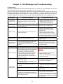
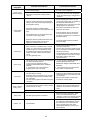
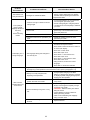
Chapter 4 – Text Messages and Troubleshooting………………………………………………...
43
4.1 Messaging……………………………………………………………………………………
43
4.2 Other Operational or Fault Problems……………………………………………………...
48
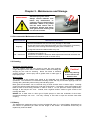
Chapter 5 – Maintenance and Storage………………………………………………………………
50
5.1 Recommended Maintenance Schedule …………………………………………………..
50
5.2 Cleaning………………………………………………………………………………………
50
5.3 Battery………………………………………………………………………………………...
50
5.4 Base Station………………………………………………………………………………….
51
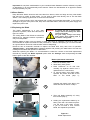
5.5 Replacing the Blade ………………………………………………………………………...
51
5.6 Splicing the Perimeter Wire ………………………………………………………………..
52
5.7 Winter Storage……………………………………………………………………………….
5.8 Batteries Replacement……………………………………………………………………..
52
53
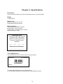
Chapter 6 – Specifications…………………………………………………………………………...
54
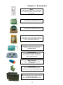
Chapter 7 – Accessories…………………………………………………………………………….…
55
Tips for maintaining your lawn……………………………………………………………………….
56
Friendly Robotics RM Series Limited Warranty…………………………………………………...
57
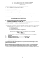
EU Declaration of Conformity…………………………………………………………………….…..
58
3
Safety Warnings & Precautions
Training and Instructions
1. Read this manual carefully before operating Robomow. Be familiar with the controls and the
proper use of Robomow and follow all safety and warning instructions.
2. Do not use Robomow for any purpose other than for which it is intended.
3.
4.
5.
6.
Never allow children or people unfamiliar with these instructions to operate Robomow.
Never mow while people, especially children, or pets are nearby.
The user is responsible for accidents or hazards occurring to other people or their property.
It is strongly recommended to use the ‘Child Guard’ or ‘Anti theft’ menu option in order to
prevent operation by children or other who are not familiar with the safe operation of the mower
7. The appliance is not to be used by children or persons with reduced physical, sensory or mental
capabilities, or lack of experience and knowledge, unless they have been given supervision or
instruction. Children should be supervised to ensure they do not play with the appliance.
8. Warning! When there is a risk of lightning storm, disconnect the perimeter wire from the Base
Station/ Perimeter Switch and the Power Supply 230V/120V plug from the mains socket
Preparation
9. Make sure to layout and set up the perimeter wire according to the instructions.
10. While mowing using a Remote Control always wear substantial footwear and long trousers.
11. Periodically inspect the area mowed by Robomow, and remove stones, sticks, wires, bones and
other objects. Objects struck by the blade may be thrown and cause severe injuries to people.
12. Only use accessories and attachments designed for this product.
Operation
13. Never let Robomow operate without supervision.
14. When using the Remote Control mow only in daylight or in a good artificial light.
15. Do not operate Robomow using the Remote Control when barefoot or wearing open sandals.
Always wear substantial footwear and long trousers.
16.
17.
18.
19.
Avoid operating Robomow on wet grass. Do not use it in rain.
When using Remote Control always be sure of your footing on slopes.
Do not operate the mower on slopes greater than 18 degrees.
Keep all guards, shields, safety devices, and sensors in place. Repair or replace damaged parts,
including decals. Do not operate Robomow if any parts are damaged or worn.
20. Do not operate Robomow if any safety feature or device is damaged or inoperable.
21. Do not attempt to disable or defeat any safety feature or device.
22. When using the Remote Control always switch on the motor according to instructions and with
feet well away from the blade.
23. This machine has sharp rotating blade! Never operate the mower if unattended; keep bystanders,
children and pets away from mower when in operation.
24. Never allow anyone to ride or sit on mower.
25. Keep hands and feet away from the cutting blade and other moving parts.
26. Never pick up or carry this appliance while the motors are running.
27. Never attempt to service or adjust the mower while it is in operation.
28. Never raise the mower or attempt to inspect the blade while the mower is operating.
29. Always remove the fuse before lifting the mower or attempting any adjustments.
4
Base Station
30. Never let Robomow operate without supervision.
31. When programming the automatic start times and days, insure these windows of operation are
programmed when children, pets and other bystanders are not on the lawn.
32. Do not place metal objects in the area of the Base Station contacts.
33. After removing the fuse from the mower always reset the current time and date. Failure to do so
may result in non-intentional operation of the Robomow, which may cause sever bodily injuries.
34. Do not spray water directly into the Base Station area.
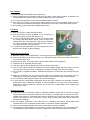
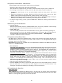
Transport
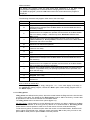
Bumper
To safely move from or within the working area:
35. Use the Remote Control (available as an accessory) to
drive it from place to place (See section 2.4).
36. In case of different height level or stairs, turn off the mower
by pressing the Main Switch button, lift the bumper door,
located at the top of the Robomow, and carry the mower by
the carrying handle, while the rear bottom side is laying on
your thigh, as shown in the right figure.
37. In case of long transportation by car it is required to remove
the fuse and use the original packaging.
Maintenance and storage
38. Maintain, service, and store Robomow according to the instructions (refer to chapter 5).
39. Remove the battery fuse before working on or lifting Robomow. Remove the battery fuse before
any maintenance is done.
40. Keep all nuts, bolts, and screws tight to assure safe condition of this appliance.
41. Replace worn or damaged parts for safety.
42. Use heavy gloves when inspecting, servicing or replacing the blade.
43. Use only the original equipment, batteries and power supply/charger with this mower. Incorrect
use may result in electric shock, overheating or leakage of corrosive liquid from the battery.
44. Do not open or mutilate the battery. Released electrolyte is corrosive and may damage the eyes
or skin.
45. Wear eye protection and use gloves when setting the perimeter wire and driving the wire
stakes/pegs. Firmly drive all pegs in order to keep the wire from becoming a tripping hazard.
46. Do not use the power supply/charger if the cord has damaged.
47. A spark may be created when inserting the fuse to the robot. Therefore it is forbidden to perform
these tasks close to flammable materials. It is also forbidden to use spray or any other cleaning
materials for cleaning electronic contacts, due to this risk of inflammation when inserting the
power pack or fuse.
Product end of use
48. Robomow and its accessories should be collected separately at the end of their life to prevent
waste electrical and electronic equipment from ending up in landfill sites, to promote the reuse,
treatment and recovery of electrical and electronic equipment in purpose to preserve, protect and
improve the quality of the environment, protect human health and utilize natural resources
prudently and rationally.
49. Do not dispose Robomow or any other part of it (including the Charger, Base Station and
Perimeter Switch) as unsorted municipal waste – it should be collected separately.
50. Ask your local distributor/dealer about return and collection systems available.
51. Do not dispose of the batteries in a fire and do not place used batteries in your household trash.
The batteries must be collected, recycled, or disposed of in an environmentally sound manner.
5
Warnings Decal Definitions
These are the symbols on Robomow; Read them carefully before operating Robomow.
DANGER! Sharp rotating blade. Keep hands and feet away.
Serious injury can occur. Caution – Do not touch rotating blade
1
2
3
4
5
6
7
1.
Safety alerts symbol – WARNING - this is a dangerous power tool. Use care when operating
and follow all safety instructions and warnings.
2.
3.
4.
Read operator’s manual – Read user instructions before operating your Robomow
Hazard of Thrown or flying objects - Whole body exposure, take caution.
Keep a safe distance from the machine when operating
Keep people in particular children, pets and bystanders away from the area in which
Robomow is being used.
Severing of toes or fingers - Rotary mower blade
Risk of injury from rotating cutting blade. Keep hands and feet away and do not attempt to
lift Robomow from this area.
5.
6.
Remove the Fuse before working on or lifting Robomow.
7.
Do not ride on Robomow.
Disposal of old Electrical & Electronic Equipment
Do not dispose Robomow or any other part
of it as unsorted municipal waste – instead it shall be handed
over to the applicable collection point for the recycling of
electrical and electronic equipment.
EC Conformity
This product conforms to the applicable EU Directives
6
Robomow® Safety Features
1. Child Guard / Safety Guard (Level I)
This menu option offers a safety feature to help prevent children or others not familiar with the safe
operation of the mower to operate it freely.
2. Anti-Theft / Safety Guard (level II)
The anti-theft system provides the user a disabling function that will prevent anyone from
using or driving the Robomow unless they have the valid code to enter. You will be prompted
to enter a four-digit code of your choice to use as your personal security code.
3. Lift Sensor
There is a Hall-Effect Sensor (Magnetic Position Sensor) located in the front side of
Robomow. In case the front of the mower is raised approximately 1-inch from its resting
position on the ground during blade operation, the blade will immediately stop rotating (< 1
second).
4. Tilt Sensor
There is an optical sensor located in the front side of Robomow. In case the front of the mower
is lifted up towards a vertically position, the blade will stop immediately and Robomow will
warn about it and instruct the user to remove the fuse before lifting Robomow.
5. Bumper Sensor
The bumper is equipped with Hall Effect sensor activates when the mower strikes a solid,
fixed object and when the bumper cover is open. When the bumper sensor is activated, the
mower will stop the rotation of the blade immediately (<1 second), will stop movement in that
direction and reverse itself away from the obstacle.
6. Emergency Stop Button
Located on the control panel, red in color. Pressing this button at any time during operation
will stop all mower movement and stop the rotation of the blade immediately (<1 second).
7. Batteries Fuse
Located below the bumper cover, on the left side of Robomow. Removing the battery fuse will
prevent any operation of the Robomow. It is required to remove the fuse before lifting
Robomow and before any maintenance is done.
8. Two-Step Operator Presence Control
While in manual mode using the remote control, it requires two independent finger actions in
order to engage the mower blade. Once engaged, the mower blade button must remain
depressed to continue blade operation. Once released, the two-step engagement process
must be repeated.
9. Electronically Controlled Charging System
Robomow is equipped with an on-board charge control system. This allows you to keep the
charger connected at all times, even after the battery is fully charged. The control system will
prevent an overcharge to the battery and keep it fully charged and maintained for the next
use.
10.Sealed Batteries
The batteries that operate the Robomow are completely sealed and will not leak any type of
fluids, regardless of position. In addition, the batteries contain a one-time-use fuse in the
event of a short-circuit or power malfunction.
7
11.Base Station/Perimeter Switch and Perimeter Wire
Robomow cannot operate without a perimeter wire installed and activated through the Base
Station/Perimeter Switch. In the event the Base Station/Perimeter Switch is turned off or
otherwise fails to function, Robomow will stop operating. Likewise, should a break in the
perimeter wire occur Robomow will again stop operation. A break in the perimeter wire prior
to operation will prevent Robomow from operating. It can only operate within the boundary of
the perimeter wire.
12.Automatic warning alert before operation
When the mower is scheduled to start the automatic operation from the Base Station per a
scheduled time, a warning buzzer and the operating lamp will activate 5 minutes prior to
operation. This is a warning notification to clear and inspect the area.
13. Over-heat Monitoring Protection
The blade motor and each of the two wheel drive motors are monitored continuously during
operation for any situation that may cause these motors to over-heat. In such event,
Robomow will stop operation of at least that motor and possibly the mower itself and indicate
that the motor is cooling down. While unusual, this may happen when the mower is on grass
that is severely overgrown; the underside of the mower is clogged from poor cleaning
maintenance; the mower has encountered an obstacle that is unable to activate the bumper
sensor preventing it from moving; or a problem landscape area has caused the mower to get
stuck and is preventing it from moving.
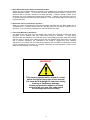
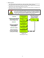
WARNING!
This warning symbol will be found at several
points throughout the pages of this manual.
It is intended to highlight an important safety,
warning or cautionary message.
Please pay particular attention to these
areas and be sure you fully understand
the message before proceeding.
8
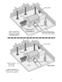
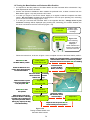
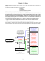
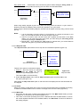
How It Works
A one-time setup is required before operating the Robomow; a small wire, called the perimeter
wire, is place around the edge of the lawn and any other areas where you do not want the mower to
enter.
Small pegs are supplied with the Robomow and they are used to fasten and hold the perimeter wire
to the ground, below grass level; the wire will soon disappear under the growth of new grass and will
not visible.
The Base Station is placed along the perimeter wire and it has two main functions:
-
To generate a small signal along the perimeter wire (very low voltage);
-
To charge the Robomow batteries.
After completing the one-time set-up of wire around the lawn including the Base Station, set the
weekly program and forget about mowing for the entire season!
Robomow will leave the Base Station on the day and time scheduled in the automatic weekly
program; it will mow the lawn and will drive back for charging in the Base Station to be ready for the
next operation.
When Robomow leaves the Base Station it automatically starts the signal carried through the Base
Station; the signal creates a virtual wall, which is visible only to the Robomow, keeping the
Robomow inside the lawn preventing it to cross over area where you do not want it to enter.
Base Station generates
a signal along the wire
and it used to charge
Robomow batteries
Trees large enough
to allow Robomow to
bump into; do not
require a perimeter
wire around it
Robomow detects
the signal and
changes direction as
it reaches the wire
Perimeter Wire as
a virtual wall,
visible only to
Robomow
Tree with hole or flowers around;
require placing a wire around it
9
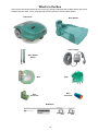
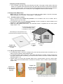
What’s in the Box
Open the box and lift the Robomow from its carrying handle; Robomow and the Base Station are bound
together with two strips; cut the strips and pull back the Robomow from the Base Station.
Robomow®
Base Station
Power Supply
Base Station
Stakes
Wire
Pegs
Wire
Connector
Plot
Connector
RoboRuler
10
Chapter 1 - Base Station & Perimeter Wire Setup
1.1 Preparations
Read carefully the Operating and Safety Manual prior to setup.
It is recommended to mow your lawn using a conventional lawn mower and water the ground
before starting the setup for easier driving of the pegs.
Confirm all parts for the setup are included (refer to ‘What’s in the Box’ page 10).
During the setup you will also need the following tools:
Hammer
Combination
Small flat and
Pliers
Philips screwdrivers
Figure 1.1 – Tools required for the setup
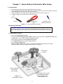
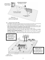
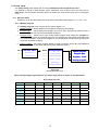
1.2 Planning The Setup
IMORTANT INFORMATION! Before starting the setup, it is necessary to first
read this chapter in order to be aware of all setup rules and instructions so you are
able to determine the best location for the Base Station and the perimeter wire layout.
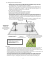
1.2.1 Base Station Location
Set it in the biggest plot or zone;
It should be placed along the outer edge (if setup on the lawn area) or outside the lawn (refer
to paragraph 1.3.2 for external setup of the Base Station);
In the back yard, where it is not visible to the street;
In a shady spot (better for a longer battery lifetime);
On a relatively level ground;
Close to a wall socket (230V / 120V) – the length of the low voltage cable is 15m (50ft)
(Note: the length of the low voltage cable must not be changed).
Base Station
location
Base Zone
Zone A
Distance between
wires greater
than 1m (3ft)
Base Zone
Wires leading to the next plot
are parallel and touching.
The gap between them
is for illustration only.
Figure 1.2 Base Station Location
11
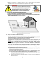
Note: The power supply is suitable for outdoor use, yet it is required placing it in a sheltered
place, dry location, which is well ventilated and not exposed to direct sunlight.
WARNING!
Serious Injury Can Occur! When placing the power
cord leading to the Base Station, insure it is fastened
securely to the ground and does not present a
tripping hazard.
Do not cross over surfaces such as sidewalks and
driveways where it cannot be fastened securely.
Place the Base Station at least one-meter from corners;
Position the Base Station with its fence facing to the inside of the lawn;
Robomow is impervious to water and rain, however it is recommended to place the Base Station
away from sprinkler heads for maximum protection.
Max 15m (50ft)
The Fence
should be
inside lawn
Low voltage
cable
Min 1m (3ft)
from a corner
Figure 1.3 Base Station distance from wall socket
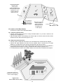
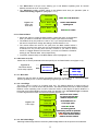
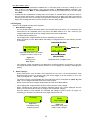
1.2.2 Multiple Zones/Areas And Narrow Passages
Your home may require more than one zone to be set up in order for the Robomow to work in all
of your lawn effectively. Where grass areas are not contiguous, or are separated by fences,
sidewalks or other objects, it is required to make each of these a separate zone.
When setting separated zones there are two options to lay the wire:
Option A: All zones are looped together and connected to the Base Station. Perimeter wire can
be as long as 500 meters (1650ft) in one loop when connected to the Base Station (Figure 1.4).
Option B: There are separated zones that connected to the Base Station and the Perimeter
Switch (available as an accessory- see Chapter 7). The Perimeter Switch can be moved between
different zones (Figure 1.5).
To mow other areas, simply drive or carry Robomow to the area you want to mow and operate it.
In this way, if one zone needs a shorter operating time than another, it can easily be set (Chapter
2.1.2). When this area is completed, drive the mower back to the station for re-charging.
Determining the distance between adjacent perimeter wires:
1. If lawns are installed by the same perimeter wire that is connected to the same source (Base
Station / Perimeter Switch), then it is enough to keep a distance of one meter between the
wires to prevent interference in operation.
2. If lawns are installed using different perimeter wires that are not connected, and each has its
own source (Base Station / Perimeter Switch), then one of the following is required:
a. Maintain a minimum distance between the wires (30-50cm) to allow overlap between
mowing zones, but synchronize between the mowing schedules to confirm there will not
be interference between the zones. OR
b. Keep two meters between the perimeter wires with no need to synchronize between the
operation schedules.
12
Base Station
Base Zone
Zone B
Zone A
While the picture shows
two wires separate, they
should be adjacent
Figure 1.4 (Option A)
Three zones are looped
together and connected
to the Base Station
Maximum length of wire
connected to the Base Station
in one loop is 500m (1650ft)
Base Station
Base Zone
Zone B
Distance between
wires is larger
than 1m (3ft)
Distance greater
than 1m (3ft)
Zone A
Figure 1.5 (Option B)
Separated zones, where grass
areas are not contiguous
13
Where grass areas are contiguous, Robomow will automatically mow all zones and drive back for
recharging in the Base Station at the end of each operation.
The area that connects two attached big areas is called a narrow pass.
There are two types of narrow passes (Figure 1.6):
Base Station
Base Zone
Narrow Pass Type A
At least 1m (3ft) between
wires so Robomow can
effectively navigate
through in order to move
between the two areas
while mowing the lawn.
Base Zone
Base Zone
Figure 1.6 Multiple areas with narrow passes
Narrow Pass Type B
Distance of 26 cm / 10”
the shorter distance of the
RoboRuler).
Robomow will drive between
areas while following the
Perimeter Wire, but it reduces
the chance that it will cross
while in scanning (mowing of
the inner area)
Type A: At least 1m (3ft) between the wires so Robomow can effectively navigate through in order to
move between the areas during the operation.
Type B: Distance of 26cm (10 inches) between the wires (the shorter measurement of the RoboRuler),
so Robomow can follow the Perimeter Wire in order to start the operation in the required area,
but it reduces the chance that the mower will cross between the area while in scanning (mowing
of the inner area). When setting narrow pass type B, it is required to set different entry points in
order to start mowing in the different areas (to set ‘Entry points’ refer to Paragraph 2.1.1.2).
Setup of Narrow Pass Type B, should be 26cm (10 inches) wide all along the pass, but should be set as
a broken line to reduce the chance that the mower will cross between the areas during the operation.
Perimeter Wire
Base Zone
Pegs
Narrow pass width is 26cm,
but it is setup as a broken
line to prevent Robomow
crossing between the areas
during operation. When the
narrow pass length is
longer than 2m, it is
recommended break the
line in 2 points, as shown at
the right.
RoboRuler
26cm /10in width - the shorter
distance of the RoboRuler
Base Zone
Figure 1.7 Narrow Pass Type B setup
14
Base Zone
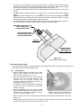
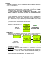
1.2.3 Defining Obstacles-Perimeter Islands
Obstacles that are relatively rigid and higher than 15cm (6 inches), such as trees, phone
poles and power poles can be left in the lawn without any consideration during the wire setup.
The Robomow will turn when it collides with this type of obstacle.
Other obstacles such as, flowerbeds, fountains and small trees, must be protected from the
Robomow using the perimeter wire. This is done as part of the setup process and is commonly
referred to as a perimeter island. However, for the most gentle and silent operation, it is
preferable to demarcate all fixed objects in the working area.
To create a perimeter island (Figure 1.8):
Take the wire from the perimeter section closest to the obstacle;
Peg it around the obstacle, using the RoboRuler short distance;
Returning back to the same spot of the edge you started from;
The wires leading to the perimeter island and coming back to the edge should be parallel and
touching BUT they cannot be crossed. The wires to and from the perimeter island can be
secured with the same pegs. The mower will not recognize these two wires and mow over
them as if they do not exist. The single wire around the perimeter island will be recognized and
prevent the mower from entering this area.
Areas with obstacles grouped closely together should be covered by a single perimeter island
or if they are close to the edge of the lawn, leave them out of the designated area.
Perimeter Wire
Perimeter Switch
While the picture
shows two wires
separate, they
should be adjacent
and placed under the
same pegs
Direction of set-up
followed around obstacle
Min distance of 1m (3ft) between two adjacent
Figure 1.8 wires of perimeter islands otherwise demarcate
Perimeter Islands Setup
them together as one perimeter island
Caution! Setting the Perimeter Wire
counter-clockwise around the
obstacle will cause Robomow to
drive into the island".
1.2.4 Slopes
The max slope allowed for the Perimeter Wire to be laid on is 15% (see area marked as 'A' in Figure 1.9).
The Perimeter Wire should not be laid across a slope that is steeper than 15cm (6in) per distance of 1
meter/3.3ft (15%). There is a risk that Robomow will find it difficult to turn and might cross the wire outside,
especially in damp weather conditions, as the wheels can slip on the wet grass.
However, the perimeter wire can be laid across a slope steeper than 15% if there is an obstacle (fence, wall
or dense hedge) that can prevent Robomow from slipping out of the area.
The maximum slope limit Robomow can mow inside the working area is 33%, roughly equals to 33cm
(1ft) of rise per 1 meter (3ft). In any event, a slope that causes the front of the mower to raise from the
ground while climbing is too steep and should not be included as part of the cutting area (see area
marked as 'B' in Figure x). Sloping area greater than 33% cannot be included in the working area.
15
This area should be
left out of the
working area
as the perimeter wire
cannot be laid in slope
greater than 15%
(15cm height per
distance of 1m)
C
D
B
A
x
Slope
0-33%
Long distance
of RoboRuler
34cm / 14inch
Robomow can mow
areas inside the
working area with
slope up to 33 cm
per distance of
1 meter (33%)
Slope
0-15%
0-15 cm
100 cm
1.3 Location of the Base Station
There are two options to set the Base Station:
1.3.1 Internal (inside the lawn)
Choose a place where you want to setup the Base Station in your lawn, based on the
inputs given in paragraph 2.1.
Place the Base Station concomitantly to the lawn edge on the lawn where the fence faces
towards the inner side of the lawn (Figure 1.13).
1.3.2 External (outside the lawn)
Choose a place outside the lawn where you want Robomow to be docked and charged.
Confirm the pass between the lawn and the outside area is smooth with no height
difference, so Robomow will not get stuck and will follow the wire smoothly.
The surface between the lawn and the Base Station should be hard (such as a sidewalk or
rigid ground) and not sandy or stoney, so Robomow will not slip or get stuck on it.
The area between the lawn and the Base Station should be clear of obstacles and objects.
Smooth pass between the lawn
and the area around with no
height difference
Hard surface clean from
obstacles so Robomow can
drive on without slipping
Figure 1.10 –
External Base Station Setup
16
The setup of the entering to the narrow pass leads to the Base Station should include
triangles to reduce the chance that Robomow will enter towards the station while mowing
the inner area (scanning); to perform the triangle setup refer to Figure 1.7.
The distance between the wires lead to the Base Station and back to the lawn is 26cm (10
inches).
The Base Station should be placed on the right wire of the narrow pass (when standing
inside
the
lawn).
Important: as the two wires are very close and affect the wire sensors readings, the Base
Station should not be aligned with the central lines marked on the Base Station; it should
be placed with a shift of 10-20cm (4-8 inches) to the right.
It is reccomneded to placed the Base Station at least 25cm (10 inches) before the end of
the external pass to allow the mower smooth entrance to the Base Station.
Base Station is placed with a right
shift of 10-20cm (4-8“)
(not aligned with the wire)
R
(u eco
p m
to m
3m en
d
/1 ed
0f
t)
Recommended to continue
the wire for at least 25cm
(10”) after the Base Station
26cm /10“
Triangle as done in
narrow pass type B
(refer to Figure 1.7)
Figure 1.11 –
External Base Station Setup
1.4 Perimeter Wire Setup
Now, knowing the location of the Base Station and the planning of the wire layout, you can begin to
setup the Perimeter Wire in the Base zone.
1.4.1 Starting Point
Place the Base Station according to your plan
with the fence towards the inner side of the
lawn, as shown in Figure 1.11 or 1.13;
Puncture the plastic covering of the perimeter
wire and pull the wire ends with the plot
connector out of the plastic covering; The
connector should be connected to the wire in
the polarity show in Figure 1.12;
The plastic covering is designed as a dispenser
for the wire; so do not remove the wire spool
from the covering;
Peg the beginning of the wire to the ground
where the Base Station will be located; be sure
to leave 30cm (12 inches) to close the loop at
the end of the setup (Figure 1.13);
Figure 1.12 – Pull out the wire from the
plastic covering – do not remove the
covering; it is designed as a dispenser.
Start laying the wire to the counterclockwise direction when standing inside the lawn, as show in
Figure 1.13.
Begin pulling the perimeter wire out of the plastic covering and lay it loosely as you walk along
the area of the lawn to the direction shown in Figure 1.13;
17
Leave 30cm (12 inches) at
the starting point, where the
Base Station is located
Perimeter Wire –
do not remove the
plastic covering
Direction of wire layout
from the Base Station
The Fence should be
inside lawn
Figure 1.13 –
Direction of Perimeter Wire
layout from the Base Station
1.4.2 Laying Out The Perimeter Wire
Start setting the perimeter wire by placing pegs every few meters and at the lawn corners according
to your plan; do not forget obstacles that need to be demarcated while laying the wire.
After removing enough wire within a given section, use the RoboRuler provided to set the correct
distance from the lawn edge. The RoboRuler is used to help position the perimeter wire along walls,
fences, sidewalk, driveways, flowerbeds and other perimeter zones.
There are two basic measurements that are used on the RoboRuler (Figure 1.14).
The shorter distance is used along perimeter edges where the area outside the immediate
perimeter is free of obstacles and is the same relative height as the perimeter edge or lower
(sidewalk on the same level or flowerbeds).
The longer distance is used along perimeter edges where the area outside the immediate
perimeter has obstacles or differences in the height along the perimeter edge (walls and fences).
Long distance of
RoboRuler – where the
area outside the
immediate perimeter has
obstacles or differences in
the height along the
perimeter edge
Short distance of
RoboRuler - where the
area outside the
immediate perimeter is
free of obstacles and is the
same relative height as the
perimeter edge or lower
Figure 1.14 –
Using the RoboRuler
18
Important
If the lawn's edge borders with a pond, swimming pool or watercourse or where the grass
level is higher than 70cm (2ft) from the edge around it, then it is required to keep a
distance of at least 1.2m (4ft) between the wire and the water (or chasm) otherwise
supplement a fence or the same along the lawn's edge, so Robomow can detect it. The
height must then be at least 15cm (6 inch). This will prevent Robomow, under any
circumstances, from crossing the wire outside the working area
1.4.3 Fastening The Wire To The Ground
It is not necessary to bury the perimeter wire, though you may do so if you wish, up to 10 cm
(4 inches) deep.
Small pegs or stakes are supplied with the Robomow and they are used to fasten and hold the
perimeter wire to the ground, below grass level.
Initially place a minimum number of pegs to fasten the wire down. Remember that you will want to
test the wire set up before you fill in additional pegs and you may find some areas where you will
need to move the wire position slightly.
Upon hammering the peg to its final depth in the ground, pull the wire tight. It is a lot easier to insert
pegs into wet soil. If the soil is dry, water the yard before perimeter wire set up.
WARNING!
Damage to the eye is possible. Use proper eye protection and wear
appropriate work gloves when hammering the pegs. Hard or dry ground
may cause pegs to break when driving them in. In extreme cases,
watering the lawn where the pegs will be driven can be beneficial.
Pegs should be driven at distances between one
another that will keep the wire down below the
grass level and prevent it from becoming a tripping
hazard (Figure 1.15).
When properly fastened to the ground, the wire and
pegs will soon disappear under the growth of new
grass and will not be visible.
If additional wire is required in order to complete
the set-up, use the wire connectors provided, which
are water-proof, to connect between the two wire
ends, as explained in chapter 5.6.
Add pegs in to pull
the perimeter wire down
to the ground surface,
below the grass tips.
Figure 1.15 Pegging the Perimeter Wire
IMPORTANT INFORMATION!
Screw terminals or twisted cables, insulated with insulation tape is not a satisfactory splice. Soil
moisture will cause the stripped wire ends to oxidize and after a while result in broken circuit.
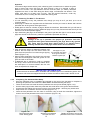
1.4.4
Completing The Perimeter Wire Setup
Once the perimeter wire is completed and pegged to the ground, the last step to complete is
attaching the perimeter wire ends to the Base Station board and testing the setup.
There are two loose wire ends where the perimeter wire set up was started (Figure 1.16).
Use the same peg to fasten these two perimeter wire ends down to the ground and twist them.
Cut the wire end without the connector so they are of equal length - removing any excess wire.
Strip back 6 mm of insulation from the wire end (Figure 1.17).
Insert the free perimeter wire into hole of connector using a small flat screwdriver; tighten the
screw to secure the perimeter wire into the connector (Figure 1.18).
Figure 1.16 Two loose wire ends
at the starting point
Figure 1.17 Strip 6mm of insulation
from the wire end
19
Figure 1.18 Tighten the screw to secure the
perimeter wire into the connector
1.4.5 Placing and Connecting the Base Station
Connect the Perimeter Wire connector to the Base
Station board (Figure 1.19).
Before securing the Power Supply cord to the Base
Station, carefully lay the length of the cord out,
beginning from the Base Station and leading to the
main power supply and insure it is fastened securely to
the ground and does not present a tripping hazard.
Do not cross it over surfaces where it cannot be
fastened, such as sidewalks or driveways. For ultimate
protection, consider an underground placement within a
protective conduit.
Connect the Power Supply cord to the Base Station
board. See Figure 1.20.
Route the Power Supply cord into the Base Station
cover as shown in Figure 1.21.
Close the cover of the Base Station; confirm it is locked
well in its place (Figure 1.22).
Figure 1.19 Perimeter Wire connection
to the Base Station
Figure 1.20 Power Supply cord connection
Figure 1.21 Routing the Power Supply
cord out of the cover
Figure 1.22 Closing the Base Station cover
Align the Base Station on the Perimeter Wire, so the wire is aligned with the two central lines
marked at the front and rear side of the Base Station, as shown in Figure 1.23. Do not fasten the
Base Station yet, as you will want to check its final position first.
Figure 1.23 Base Station alignment
Connect the power supply to a regular household receptacle 230 Volts AC.
A small flashing green light in the Base Station cover indicates the system is on and functioning
properly. Continuous beeps indicate a disconnected/broken perimeter wire. Discontinuous beeps
indicate poor splicing of perimeter wires or perimeter wire, which is too long (the max allowed in
one loop is 500 meters).
20
Flashing light
indicates the system
Figure 1.24 Base Station
Operating Panel
Continuous beeps indicate a
disconnected/broken wire
Discontinuous beeps indicate
poor splicing of perimeter wires
or perimeter wire, which is too
1.5 Robomow Preparation and Settings
1.5.1 Setting the Cutting Height
Lift the Bumper Cover from the front side of the Robomow (figure 1.25).
To change the cutting height, rotate the cutting height adjustment knob, as shown in figure 1.26.
Control Panel
Fuse location
Carrying
handle
Winter Charger
location
Cutting height
adjustment
knob
Mowing
motor
Figure 1.25 Lifting the Bumper Cover
Figure 1.26 RM510 General View
1.5.2 Inserting Batteries Fuse
Your Robomow is shipped with the batteries fuse
removed and it will not operate without it. The fuse is
assembled inside its rubber cover, located under the
Bumper Cover (Figure 1.27).
Lift the Bumper Cover, remove the partition and insert
the fuse. The fuse can be inserted in either direction.
See figure 1.27
Robomow will now power up (wake up). The Batteries
are charged at the factory and have plenty of power to
perform the initial setup and test run. However, after the
initial set-up process is completed the batteries need to
be charged 16 hours in the Base Station before the first
operation.
21
Figure 1.27 Inserting batteries fuse
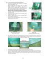
1.5.3 Robomow Settings
Control Panel
On the top of the rear side of Robomow there is a control panel. The control panel consists of a
display, keypad and operating lamp (figure 1.28).
Operating Lamp
STOP button
UP
arrow
STOP
Figure 1.28
Control Panel
GO
Main Switch
button
GO / START
button
DOWN
arrow
LCD display
window
Rain
sensor
The ‘GO’ button is used as a means to select or confirm different menu options or settings;
‘Up / Down ’ arrow keys will allow you to scroll through the menu items;
The ‘STOP’ button has two different functions: when pressing during automatic operation it will
stop Robomow and blade operation immediately and when pressing at any time during the
menu selection process it will bring you one step back in the menu.
‘Main Switch’ button is used to switch off the Robomow. It is required to switch off the
Robomow when carrying it between zones.
IMPORTANT INFORMATION!
Follow the instructions on the LCD display - Robomow will
friendly instruct you, step by step, how to complete the setup
Language, Time and Date settings
‘Language’ is the first setting you are asked to set, as Robomow wakes up. Follow the
instructions below, as shown in figure 1.29.
Language
Press GO
English (US)
Confirm
Time and Date
Press GO
00:00
dd/mm/yy
next digit
15:23
16/04/07
Confirm
Press ‘GO’
Scroll ‘UP’ or ‘DOWN’
to choose your language
and press GO to confirm
Please note that there are
‘English’ and ‘English (US)’ under
the ‘Language’ menu, as the language
defines also the ‘Time and date’ format.
Press ‘GO’
Scroll to set the time and date
and press ‘GO’ for the next digit
(‘STOP’ is used to go back)
Press ‘GO’ to confirm and continue
with the instructions at the next
subparagraph (‘weekly program’ setting)
22
Figure 1.29
Language, Time
and Date setting
Weekly Program
The ‘Weekly program’ menu allows you to set an automatic weekly program by the size of the
area connected to the Base Station (follow the steps shown in figure 1.30 below).
By setting the area of the zone connected to the Base Station, Robomow will automatically
determine the most suitable weekly program to your lawn.
Robomow will start mowing at 13:00 on the active days and will drive back for charging in the
Base Station at the end of the operation.
WARNING! Never let Robomow operate without supervision. Serious injury can
occur. If the current date and time are not set correctly or are failed to
be set when prompted, the times scheduled for automatic departure
will not be correct. Incorrect departure times can be dangerous if
children, pets or bystanders are present in the mowing area.
Press ‘GO’
Weekly program
Press GO
Choose ‘Off’ if you do not
want to use automatic
scheduled operations.
Press ‘GO’ to set an automatic
weekly program by area or
scroll to change it to ‘Off’.
Program
On
Confirm
Program
Off
Confirm
Press ‘GO’
Base zone area
Press GO
Scroll ‘UP’ to choose the
lawn area connected to
the Base Station
150 – 200 m²
Confirm
Press ‘GO’ to confirm
200 – 250 m²
Confirm
Follow the instructions
at the next subparagraph
(‘Base position’ testing)
Base position
Press GO to test
Figure 1.30
Weekly program setting
23
1.6 Testing the Base Station and Perimeter Wire Position
It is required to test the position of the Base Station and the Perimeter Wire to determine if any
small adjustments need to be made.
Position the Robomow inside the lawn towards the perimeter wire, at least 2 meters from the
Base Station (figure 1.31) and press the ‘GO’ button.
In a case you forgot to connect the Power Supply to a regular household receptacle 230 Volts
(120V), ‘No wire signal’ message will be displayed on the LCD upon pressing GO, reminding
you to connect the Power Supply (Figure 1.32).
In a case you connected the Perimeter Wire in the opposite direction, ‘Change wires in plot
connector’ message will be displayed upon pressing GO, instructing you to switch between the
two wires connected to the Plot connector (Figure 1.33).
Figure 1.32
‘No wire signal’
message
No wire signal
Press GO
Change wires in
Plot connector
Figure 1.31
Testing the Base Station position
Figure 1.33
If the following
message is
displayed –
switch between the
2 wires connected to
the Plot connector
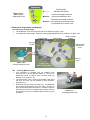
Follow the instructions, as shown in figure 1.35 to complete the test of the Base Station position:
Slightly move the Base Station, so that Robomow
enters the Base Station as centered as possible;
Reposition Robomow and press ‘GO’ for retesting
Base position
Press GO to test
Press ‘GO’ to test
the Base Station position
Follow the Robomow and
confirm that it docks properly
into the Base Station
If Robomow fails
to enter the Base
Station, it will stop
Searching base
Reposition Base
Press GO
Robomow enters successfully;
drives back from the Base
Station and stops;
Fasten the base in place
using the 2 stakes (figure
1.34) and press ‘GO’
Peg base
then press GO
Press ‘GO’ to test
wire position
Wire position
Press GO to test
Walk along the side of the
Robomow while it is following
the edge until completing one
lope of the perimeter without
striking any object (it will stay
in the Base Station).
Figure 1.34
Placement of stakes
Robomow collides
with obstacle, drives
back and stops
Wire position
Adjust the wire and press ‘GO’ to
continue testing the wire position
Figure 1.35
Testing the Base Station and
Perimeter Wire Position
24
Adjust wire
then press GO
Completing the Wire Fastening
Once complete, walk back along the perimeter and add in wire pegs to those areas of the wire
where it is not pulled down below the level of the grass tips and close to ground level. Wherever
the wire is raised or loose, it should be tightened and pegged down with extra wire pegs (distance
between pegs should be 0.5 to 1 meter (1.5-3 ft) in straight line and more when curved).
1.7 Setup in None-Base Zone
Note: Setup in a non-Base zone, which is not connected to the Base Station, requires a Perimeter
Switch (available as an accessory - see Chapter 7 - Accessories).
1.7.1 Perimeter Switch Location
Find a convenient spot outside the perimeter of the non-Base zone, but a location that is
relatively easy for you to access.
The Perimeter Switch must be mounted vertically in order to maintain its’ water resistance and
preferably in a dry and sheltered location.
Close to a wall socket (230V/120V) – the Perimeter Switch is supplied with an indoor power
supply (Figure 1.36).
The Perimeter Switch MUST be
mounted vertically in order
to maintain its’ water resistance
Wires leading from the perimeter to the
Perimeter Switch are adjacent and touching.
Figure 1.36
Perimeter Switch
Location
2 meters
low voltage
cable
Indoor Power
Supply
1.7.2 Placing the Perimeter Switch
The Perimeter Switch connector is designed for quick and easy disconnection that allows you to
easily move the perimeter switch between plots.
The Perimeter Switch also comes with a large stake that fastens to its back, making transfer from
one plot to another easier by allowing you to disconnect the switch and move it with the stake still
attached (Figure 1.37).
Another option is to mount the Perimeter Switch onto a vertical surface, such as a wall or deck
railing. There are three small bosses on the back of the switch cover in order to mount it this way.
(Figure 1.38).
Figure 1.38
Figure 1.37
Perimeter Switch
with stake
attached
Squeeze the tabs
on both sides to
remove cover
Mounting the Perimeter Switch using
three mounting bosses on back cover
25
1.7.3 Laying Out The Perimeter Wire
Now, knowing the Perimeter Switch location, you can begin the setup of the Perimeter Wire, as
was explained in articles 1.2 and 1.3. The perimeter wire setup in a Base and non-Base zone is
identical in terms of placement and fastening;
At the location of the perimeter switch, strip back 5 mm (0.2 inches) of insulation from the wire end.
Insert the wire end to the left side of the plot connector, as shown in figure 1.39 and tighten the
screw.
Peg/fix the beginning of the wire where the Perimeter Switch will be located;
Lay the wire from the Perimeter Switch to the lawn; be sure to leave enough wire at the beginning
to close the loop;
Start laying the wire to the counterclockwise direction when standing inside the lawn, as show in
Figure 1.39.
Connect the wire end to
the left side of the plot
connector (when looking
towards the screws)
Figure 1.39
Connecting the wire end to the
left side of the connector and
perimeter wire layout direction
Perimeter wire layout
in clockwise direction (as view from
the inner side of the lawn)
1.7.4 Completing And Testing The Setup
Once the perimeter wire is completed and pegged to the ground, the last step to complete is
attaching the Perimeter Switch to the perimeter wires and testing the setup.
Pull the two loose perimeter wire leads taut and peg them down to the ground (figure 1.36),
adjacent to one another, as you move away from the perimeter and towards the Perimeter Switch
location (use the same pegs to attach the two wires from the lawn to the Perimeter Switch
location).
At the location of the perimeter switch, cut the loose perimeter wire so both wires are of equal
length, removing any excess wire. Strip back 5 mm (0.2 in) of insulation from the wire end. Insert
the wire end to the free hole in the connector and tighten the screws as shown in figure 1.40.
Plug the perimeter wire connector into the Perimeter Switch (see figure 1.41)
Using a small flat
blade screwdriver,
tighten the screw
to secure the perimeter
wire into the connector
Figure 1.40
Inserting and Fastening
Perimeter Wire to Connector
Figure 1.41
Plug the plot connector into
the Perimeter Switch
26
Take the Perimeter Switch and squeeze the
tabs on both sides of the Perimeter Switch,
(as shown in figure 1.42A) and remove the
back cover from the Perimeter Switch.
Figure
1.42A
Connect the power supply plug to the
Perimeter Switch board (see figure 1.42B)
and reassemble the Perimeter Switch.
Connect the power supply to a regular
household receptacle 230 Volts AC;
The Power Supply is for indoor use only, thus
place it in a dry location, which is well
ventilated (do not cover it with plastic bag); be
sure the power supply and the connection to
the low voltage cable are in a dry place and
not exposed to water and rain.
Figure 1.42B
Connect the power supply plug
to the Perimeter Switch board
Press the ‘ON’ button. A small flashing green light next to the ‘ON’ button indicates that the
system is on and functioning properly. The Perimeter Switch also has indicators for a
disconnected/broken perimeter wire and for poor wire splicing. Figure 1.43
Flashing light indicates
the system is on
ON button
Indicates a
disconnected/broken wire
Figure 1.43
Perimeter Switch
Operating Panel
Indicates poor splicing of
perimeter wires or perimeter
wire, which is too long
The Perimeter Switch has an automatic shutoff feature, eliminating the need for you to turn it off
after each use. It will shut itself off after 12 hours of operation. You may manually turn the
perimeter switch off by pressing the ‘ON’ button continuously for 3 seconds. A beep will be heard
after the three seconds, indicating you may release the button and the switch is off.Test the
perimeter wire setup by choosing the ‘Wire position’ menu as shown in figure 1.44. Robomow
will follow the wire, while the mowing motor is switched off to prevent any damage to the
perimeter wire after the initial setup; Walk along the side of the Robomow while it is following the
edge until completing one loop of the perimeter without striking any object; If Robomow collides in
obstacle, it stops and drives back to allow you adjusting the wire position.
Main display Press ‘GO’
Scroll down until
‘Settings’ is displayed
Mow zone: Base
Press GO
Zones setup
Press GO
Press ‘GO’
Settings
Press GO
Scroll up until ’Wire
position’ is displayed
Child guard
Press GO
Press ‘GO’
Wire position
Press GO
Press ‘GO’ and follow
Robomow while following
the Perimeter Wire
Wire position
Press
to test
WireGO
position
27
Figure 1.44
Testing the Perimeter
Wire position
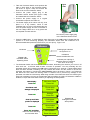
Chapter 2 - Menu
Chapter 2 introduces Robomow menu functions. To use the control panel read the instructions in
paragraph 1.5.3.
The main menu consists of four options: 2.1 Zones setup
2.2 Settings
2.3 Information
2.4 Service (password is required)
Note: the numbers 2.1-2.3 refer to the headings on the coming pages.
To browse through the main menu and the submenus, use the ‘GO’ button as a means to select or
confirm different menu options or settings. Pressing the ‘GO’ button will generally select or confirm the
text message shown on the second line of the LCD. There are several settings, which the user can make
changes to and features that can be enabled/disabled. Pressing the ‘STOP’ button at any time during the
menu selection process will bring you one step back in the menu. To scroll between the submenus use
the ‘UP’/’DOWN’ arrow keys.
To see the main menu functions (options 2.1 to 2.4 - Figure 2.1), follow one of the following options:
1. When the mower is out of the Base Station scroll down to the ‘User options’ display and press
‘GO’;
2. When the mower is in the Base Station, simply scroll down to the menu you want.
Figure number 2.1 shows the main menu and the submenus available under each of the options. There
are more submenus in the next level of the menu tree that are explained in the next pages of this chapter.
2.1.1
Scroll UP/DOWN
using the arrow keys
to the menu you want
and press GO to see
the options below the
chosen menu
2.1
Zones setup
2.2
Settings
User options
Press GO to receive
options 2.1 to 2.3
2.1.2
Set Zone: Base
Set Zone: A
Set Zone: B
2.2.1
Child guard
2.2.2
Anti theft
2.2.3
Time and date
2.2.4
Rain sensor
2.2.5
Language
2.2.6
Eco mode
2.3
Information
2.2.7
Signal type
2.4
Service
2.2.8
Blade replaced
2.2.9
Wire position
2.2.10
Delay operation
Password required
Figure 2.1
Robomow menu options
28
2.3.1
Operation
2.3.2
Battery
2.3.3
Temperatures
2.3.4
Configuration
2.3.5
Last stop cause
2.1 Zones setup
The ‘Zones setup’ menu allows user to set the parameters that are specific per zone.
It is possible to set up to three different zones: zone Base, zone A and B, when the main zone is
Base Zone, the area where the Base Station is located (for multi zones setup refer to paragraph
1.2.2).
2.1.1 Set Zone: Base
Enables to set all the parameters that are specific to Zone Base (paragraphs 2.1.1.1 to 2.1.1.6).
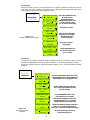
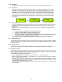
2.1.1.1 Weekly program
The ‘Weekly program’ menu consists of four options (figure 2.2):
a. Update program – allows updating the program and changing the settings.
b. Program type – allows setting the program type, when every type gives a different level of
the parameter the user can set (more details will follow).
c. Program on/off - Allows user to shut off the weekly program when setting the ‘Program’ to
‘off’. A shortcut to shut off the weekly program is by pressing the main switch while Robomow
is in the Base Station. It will set the program to 'off' but will allow manual start by pressing the
GO button as well as charging.
d. Display program - the weekly program display is used to show the active days and additional
information about the last week operations (more details will follow).
2.1.1
2.1.2
Set Zone: Base
2.1.1.1
Weekly program
Update program
Set Zone: A
2.1.1.2
Entry points
Set Zone: B
Program type
2.1.1.3
Skip next start
Program on/off
2.1.1.4
Islands on/off
Display program
2.1.1.5
Work time
2.1.1.6
External Base
Figure 2.2
Weekly program menu
When setting weekly program by area, the active days will be as shown in the table below.
Active days per area
Area m2
Mon
Tue
Wed
Thu
Fri
0-50
√ √ 50-100
√ √ 100-150
√ √ 150-200
√ √ 200-250
√ √ 250-300
√ 300 and up
√ Sat
Sun
√ √ √ √ √ √ √ √ √ √ √ √ √ √ √ √ 29
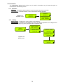
√ Program type
There are three types of weekly programs that can be set by the user:
- Set by area:
Define the area size of the zone connected to the Base Station and the start time, at
which you wish Robomow to start mowing; Robomow will determine the most efficient
weekly program to your lawn based on the area given. Follow the screens and the
instructions below (figure 2.3) to set weekly program by area:
Set by area
Base zone area
Press GO
Press ‘GO’
Set by days
Advanced
100 – 150 m²
Confirm
Scroll ‘UP’ to choose the
lawn area connected to
the Base Station
200 – 250 m²
Confirm
Press ‘GO’ to confirm
Start: 13:00
Next digit
Figure 2.3
Weekly program set by area
Start: 14:00
Confirm
30
Scroll to set the start time
and press ‘GO’ to confirm
(the ‘Start time’ is the
same for all days)
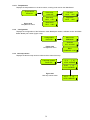
-
Set by days:
Select the days in which you wish Robomow to operate. Define the start time and the
work time, which are common to all active days; Follow the screens and the instructions
below (figure 2.4) to set weekly program by days:
Set by area
M+ T- W- T- F- S- S-
Set by days
Next day
Advanced
M+ T- W+ T- F+ S- S-
Next day
M+ T- W+ T- F+ S- S-
Confirm
The cursor indicates the day
to be set; Use the
UP/DOWN arrows to
change the day status, when
‘+’ is for active day; Press
‘GO’ to move to the next day
Press ‘GO’ to confirm
Start: 13:00
Scroll to set the start time
and press ‘GO’ to confirm
(the ‘Start time’ is the
same for all days)
Next digit
Figure 2.4
Weekly program set by days
Start: 14:00
Confirm
Work time
Press ‘GO’ to set the
working time
Press GO
Zone: Base
Max
Confirm
Zone: Base 1:30
Confirm
-
Scroll UP/DOWN to set
the work time and press
‘GO’ to confirm
Advanced:
The advanced program should be used in multiple zones, as it allows the user to set all
parameters differently per day (entry point, start time, work time and operation mode);
Follow the screens and the instructions below (figure 2.5) to set the advanced weekly
program:
Set by area
Set by days
Advanced
M- T- W- T- F- S- S-
Select day
M+ T- W+ T- F+ S- S-
The cursor indicates the day to be set; Use
the UP/DOWN arrows to move between the
days and press ‘GO’ to program the day
Select day
Start: 13:00
Next digit
Start: 14:00
Scroll to set the start time and press
‘GO’ to confirm (the ‘Start time’ is the
same for all days)
Confirm
Work time: Max
Confirm
Entry:
1
Confirm
Mode: Edge+Mow
Confirm
Figure 2.5
Advanced weekly
program
M+ T- W- T- F- S- S-
Select day
31
Scroll UP/DOWN to set the work
time and press ‘GO’ to confirm
This screen is displayed if entry points
were defined (refer to 2.1.1.2); allows
setting a specific entry point per day
Scroll to the required operation mode and
press ‘GO’ to confirm (‘Edge+Mow’ or
‘Mow’ only – ‘None’ use to cancel active day)
Scroll to the next day you want to
program and press ‘GO’
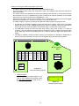
Example for using the advanced program (Figure 2.6)
-
-
The lawn in figure 2.6 has two areas with narrow pass between them;
The large area is 250m² where the small area is 50m², thus different work times are required to
each of the areas;
The mower cannot cross between the areas while working inside the lawn, but only when following
the perimeter wire, thus an additional entry point is required to start the operation in the smaller
area of 50m² (to set entry points refer to paragraph 2.1.1.2);
Robomow mows about 130m² per full operation, thus 2 operations are required to mow the bigger
area and one operation of 1:30 hours is enough to cover the smaller area;
The table in figure 2.6 shows an example of advanced weekly program for the given lawn:
On Monday and Tuesday, Robomow mows the large area of 250m² (entry point is the Base
Station); it starts at 13:00 for ‘MAX’ operating time, where on Monday it mows the edge before
entering to mow the inner area (Mode: E+M, means edge + mowing of the inner area);
On Wednesday, Robomow mows the small area of 50m² (entry point is Entry 1); It starts at
15:30 for 1:30 hours; Robomow follows the wire towards entry point 1 without mowing the edge,
as the edge was mowed on Monday (there is no need to mow the edge more than twice a
week);
Thursday to Saturday contain the same mowing cycle as defined on Monday to Wednesday in
order to mow all the area twice a week, which is required during the fast growing season.
Base Station
Entry
Day
Mon
Tue
Wed
Thu
Fri
Sat
Start
13:00
Time
MAX
MAX
1:30
13:00
13:00
12:00
MAX
MAX
1:30
250m²
Entry
Base
Base
1
Base
Base
1
2,700ft²
Mode
E+M
M
M
E+M
M
M
13:00 15:30
Sun
50m²
540ft²
Entry 1
Figure 2.6
Advanced weekly program
Display program
The weekly program display (figure 2.7) is
used to show additional information about
the last week operations except of the ‘+’
for the active days.
32
M+ T+ W+ T- F+ S- SR
m
Figure 2.7
Weekly program display
Shortcut buttons
To display the program, press the ‘UP’ arrow while Robomow is in the Base Station.
The program is displayed for 10 seconds before changing back to the main display.
To update the program, press the ‘GO’ button within the 10 seconds that the program is
displayed.
The following characters may appear under each of the active days:
Character
Meaning
+
Active day
Skipped due to low battery voltage;
(Robomow did not depart from the Base Station at the scheduled time due to
low battery voltage)
Docked before time due to low battery voltage;
(Robomow did not complete the operation and drove back to the Base Station
due to low battery voltage – relevant only when ‘Work time’ different from
‘Max’ is set)
Robomow did not return to the Base Station because of Drive over current
('Start elsewhere') or 'Drive problem'; Robomow returned to the Base Station
before time due to drive overheat.
Skipped due to mow over current detected in the Base Station before
Robomow has started the operation.
Robomow returned to the Base Station before time due to mow problem (over
current or over heat)
Skipped because the mower was out of the Base Station at the scheduled start
time
Skipped due to power problem (there is no charging voltage at departure time)
Skipped due to rain;
(Robomow did not depart from the Base Station at the scheduled time due to
rain detection)
Docked before time due to rain;
(Robomow did not complete the operation and drove back to the Base Station
due to rain detection during the operation)
Skipped due to signal problem (it may happened because of problem with wire
sensors, cut perimeter wire, poor splicing of perimeter wire or perimeter wire
which was too long).
Robomow returned to the base because of no signal for more than 1 hr
Skipped due to user choice/interference (usually ‘skip next start’ or when the
‘Program’ set to ‘off’)
Robomow did not return automatically to the Base Station because of user
interference
B
b
d
M
m
O
P
R
r
S
s
U
u
How to cancel an active day?
In weekly program set by days, simply change the ‘+’ to ‘-‘ in the main display of the days; in
the ‘Advanced’ weekly program, choose the ‘None’ option under weekly program menu in
the ‘Mode’ display.
2.1.1.2 Entry points
‘Entry points’ are defined as the points, where the mower leaves the Edge and turns into the lawn
to mow the inner area. The default of the ‘Entry points’ is set to ‘off’ in the factory; it means that
all operations of the inner area will start from the Base Station.
The ‘Entry points’ menu consists of two options (figure 2.8):
Set entry points – Allows setting up to four different entry points to your lawn in addition to the Base
Station, which is defined as an entry point by default. It is recommended to ‘Set entry points’
where there are narrow passes in order to insure the mower will cover all areas effectively.
To set the entry points, choose this option when the mower is in the Base Station; Robomow will
start to follow the perimeter wire; follow the mower and press ‘GO’ at the point you want to set;
press ‘GO’ for other points or press ‘STOP’ to end the process.
33
Entry points on/off – Allows user not to use the entry points. When setting the ‘Entry points’ to
‘off’ the mower will always start the mowing the inner area from the Base Station.
2.1.1
2.1.2
Set Zone: Base
2.1.1.1
Weekly program
Set Zone: A
2.1.1.2
Entry points
Set entry points
Set Zone: B
2.1.1.3
Skip next start
Entry points on/off
2.1.1.4
Islands
2.1.1.5
Work time
2.1.1.6
External base
Figure 2.8
Entry points
When using weekly program by area or by days, the entry points are used in a cyclic mode i.e.
Robomow will start at a different entry point every operation, in a cyclic mode.
When using the advanced weekly program, the user has the option to set any entry point he wants
per day.
Notes:
1. It is not necessary to set all 4 points, if you find that 2 or 3 points are enough to your
lawn, you can stop the mower at any time during the process.
2. There is no need to wait until the mower will complete the drive back to the Base
Station; you can stop the mower at any time you want during the ‘Set entry points’
process by pressing the ‘STOP’ button.
3. Manual start - Upon pressing the ‘GO’ button for manual start, you will be asked to
select the entry point, if you have set them previously.
2.1.1.3 Skip next start
The ‘Skip next start’ option allows user to skip the next scheduled operation (figure 2.9).
2.1.1
2.1.2
Set zone: Base
2.1.1.1
Weekly program
Set zone: A
2.1.1.2
Entry points
2.1.1.3
Skip next start
2.1.1.4
Islands
2.1.1.5
Work time
2.1.1.6
External base
Set zone: B
Figure 2.9
Set Zone: Base options
There are two options to activate this option:
1. Shortcut – when the mower is in the Base
Station press the ‘STOP’ key first to
display the right display (figure 2.10).
Skip next on
Confirm
Figure 2.10
Skip next start
Then press ‘GO’ to confirm the skip.
2. Under ‘Set Zone: Base’ menu scroll to ‘Skip next start’ option and press ‘GO’ to set
the option (see figure 2.9).
After setting the ‘Skip next start’ option to ‘on’ the mower will display the next start time after the
one skipped.
2.1.1.4 Island
Setting this option to ‘off’ allows the mower to acquire the Perimeter Wire immediately as starting
to search for the Base Station with no need to converge to the end of the lawn (figure 2.9).
2.1.1.5 Work time
Allows the user the option of setting the operating time from the ‘MAX’ default setting to times
ranging from 15 minutes up to 2:00 hours (figure 2.11).
This menu is used when operating the mower in Manual Start from the Base Station, as when
the mower departes automatic from the Base Station, the ‘Work time’ it used is as defined in
the weekly program.
34
The ‘Work time’ is set per zone, allowing you to set different operating time for several
different zones that are of varying sizes.
The ‘Advanced’ weekly program allows to set different work time per operation (refer to
‘Advanced weekly program’ in paragraph 2.1.1.1).
Work time
Press GO
Zone: Base Max
Confirm
Figure 2.11
Setting the
‘Work time’
Press ‘GO’ to set ‘Work time’
Scroll to select different
operating time.
Zone: Base 1:30
Confirm
Press ‘GO’ to confirm
2.1.1.6 External Base
Allows the option to setup the Base Station outside the lawn; recommended
when you want to conceal the mower from people eyes while not mowing.
The default set by the producer is set to ‘off’; if you setup Robomow outside
the lawn it is required to change the setting of ‘External base’ to ‘on’.
The mower follows the wire for 5m (15ft) from the Base Station before it
enters to mow the inner area, thus it is recommended to set the Base Station
at maximum 3-4m (10-13ft) from the lawn; however if you want to set the
mower in a bigger distance from the lawn, you have to increase the ‘Distance’
setting (in the ‘External base’ menu) respectively.
To perform external setup of the Base Station refer to paragraph 1.3.2.
2.1.2 Set zone: A (or B)
Allows user to set the parameters that are specific per non-Base Station zone (figure 2.13):
Figure 2.13
Non-Base Station
zones setup options
2.1.1
2.1.2
Set zone: Base
Set zone: A
2.1.2.1
Work time
2.1.2.2
Learn edge
Set zone: B
2.1.2.3
Set default edge
2.1.2.1 Work time
Allows the user the option of setting the operating time from 15 minutes up to 2 hours and ‘MAX’
which is generally 2.5 to 3.5 hours, depending on grass type and condition.
2.1.2.2 Learn Edge
This menu option is used in a non-Base zone only. The default distance for edge mowing is
approximately 1 to 2 rounds around the perimeter. This feature allows the user to define a specific
distance in each operating zone in order to have the mower cut the edge at a specific distance. It
will remain as a learned distance until the edge is re-learned or the ‘Set default edge’ is selected.
To learn edge distance follow the instructions below (figure 2.14):
Set zone: A
Press GO
Figure 2.14
Learn edge
Scroll to the zone of which
you want to learn the edge
distance and press ‘GO’
Work time
Press GO
Scroll DOWN once to
‘Learn edge’ option
Learn edge
Press ‘GO’ to start
the learning process
Press GO
Learning edge
STOP to set
While driving around the perimeter.
Follow the mower and press the
‘STOP’ button when the desired
distance has been reached.
2.1.2.3 Set Default Edge
Selecting Default Edge restores the factory default edge distance to the specific zone selected.
35
2.2 Settings
The ‘Settings’ menu allows the user to set the options that refer to the Robomow itself and are
common to all zones (figure 2.1).
2.2.1 Child Guard
Child guard is a feature that when activated will help deter use by young children and other
unauthorized people. It will prevent operation to those not familiar with the mower. The key
sequence to unlock the guard for operation is pressing the ‘UP’ arrow key and then the ‘STOP’
key to unlock the controls. Two minutes of inactivity will re-lock the keys.
It is strongly recommended to use the “Child Guard” menu option in order to prevent
operation by children or others who are not familiar with the safe operation of the
Robomow.
2.2.2 Anti-Theft
The anti-theft system provides the user a disabling function that will prevent anyone from using or
driving the Robomow unless they have the valid code to enter. You will be prompted to enter a
four-digit code of your choice to use as your personal security code. Use the scroll arrows in
order to change each digit position to a different number and then press ‘GO’ to move to the next
digit to select. You will find a place to record your personal security code in Chapter 8 of this
manual. Be sure to record your code for future reference.
To change the password, choose the ‘Change code’ option under the ‘Anti theft’ menu. You will
be promoted to enter your old password before setting the new one.
2.2.3 Time And Date
Allows setting time and date (figure 2.15):
Time and date
Press GO
00:00 dd/mm/yy
Figure 2.15
Time and date
Next digit
10:37 23/04/07
Press ‘GO’
Scroll UP/DOWN to set the
clock and the date and
press ‘GO’ for the next digit
Press ‘GO’ to confirm
Confirm
2.2.4 Rain Sensor
The Rain sensor feature enables the mower to detect rain and skip or stop the operation as it is
detected. There are three options under the ‘Rain sensor’ menu, as shown in Figure 2.16:
Rain sensor
Press GO
Set sensitivity
Reading (29) 25
Press GO
Confirm
Rain sensor
on
Press GO
Delay after rain
Figure 2.16
Rain sensor menu
Press GO
Rain sensor off
Confirm
3h
Confirm
Set sensitivity – Enables to set the sensitivity of the rain sensor in which the mower will detect rain
below the threshold set. The default sensitivity set in the factory is 25, it means that in any reading
below 25 the mower will detect rain and will not operate. The number in the brackets shows the
actual reading of the rain sensor.
Rain sensor on/off - Allows turning the rain sensor feature off to enable operation in rain and wet
grass conditions.
Delay after rain – Enables to set time delay, in case that rain is detected by the mower before the
start time, in order to let the grass dry before the mowing is starting. For example, if the
scheduled start time is 13:00, the ‘delay after rain’ was set to 5 hours and the rain has stopped 2
hours before the scheduled start time (11:00), then the Robomow will delay the start time of the
operation and will start at 16:00 (5 hours after the rain was stopped, which is 3 hours after the
scheduled start time). The default ‘delay after rain’ set in the factory is 0 hours.
36
2.2.5 Language
Allows the user the option of viewing the LCD text in several different language versions.
2.2.6 ECO Mode
The ECO (Economic) mode feature enables operating Robomow using minimum energy
required to cut the grass and maintain the lawn. The ECO mode default is set to 'on'.
Operation in ECO mode reduces Robomow noise level during operation and allows longer
operation time. It is recommended to use the ECO mode only in zones with Base Station,
where mowing is more frequent and a shorter part of the grass is cut. If Robomow detects
high grass it will automatically increase the power of the mowing motor to enable cutting
higher grass.
Eco mode
Press GO
Eco mode on
Press GO
Eco mode
off
Confirm
2.2.7 Signal type
In some circumstances there may be interference to the wire signal caused by other wire signal
activated in adjacent lawn (neighbor that use robotic lawnmower) or by any other appliance
using similar
frequency. In case of signal interference, you may see one of the following symptoms (usually
close to
the neighbor lawn):
a.
Robomow is widely swinging when driving along the wire;
b.
Robomow changes direction without reaching the wire;
c.
Robomow crosses the wire outside the designated area;
d.
'Start inside' message is displayed although Robomow is inside the designated area and
the perimeter wire is connected in the right polarity;
If your mower faced one of the above symptoms, to change the signal type call to service
2.2.8
Blade Replaced
Choose this option after replacing the blade to restart the reminder counter. A reminder to replace
the blade again will be displayed after the next 200 hours of operation. Blade is easy to replace,
refer to section 5.5.
2.2.9
Wire Position
Allows user to test the wire position in ‘Edge’ mode while the mowing motors are switched off to
prevent any damage to the perimeter wire after the initial setup of the wire is completed.
2.2.10 Delay operation
This option allows the user to press GO but delay the operation starting time. It is useful when you
want to start the operation later in the day when the grass is dry and not early in the morning
when the grass is wet (and you have to leave for work).
To use this option, follow the steps below:
- Set the ‘Delay operation’ to X hours (choose between 1,2,3…or up to 8 hours);
- Switch on the Perimeter Switch (It is operated for 12 hours) and place the mower inside the
lawn towards the perimeter wire;
- Pressing ‘STOP’ then ‘GO’ (while holding the ‘STOP’ button) will change the display to ‘Press
GO again to skip edge’ and at the end of the warming up process, the mower will stay in place
with a message ‘Operation delayed – wait…’
- The mower will start the operation after X hours (as set in the ‘Delay operation’ menu) from the
‘GO’ pressing.
37
2.3 Information
The ‘Information’ display (refer to figure 2.1) is used for information only, it allows the option to
scroll between the following menus:
2.3.1 Operation
Total time - Indicates the total number of hours the mower has been in operation.
First operation – Indicates the date, in which the mower was first operated.
Figure 2.17
Operation menu
Operation
Press GO
Total time
253h47m
First operation
Date: 13/03/08
2.3.2 Battery
Battery voltage – Displays the current voltage of the batteries.
Last run times – Indicates the last battery run time in the last 10 operations, the voltage at the
beginning of the operation and the operation date.
Battery voltage
Battery
Press GO
12.8 25.5 12.7
Last run times
Press GO
1) 2h34m 25.8V
25/05/08
2) 2h32m 25.7V
24/05/08
Figure 2.18
Battery menu
10) 2h27m 25.7V
18/05/08
38
2.2.11 Temperatures
Displays the temperatures on the drive motors, mowing motor and on the Main Board.
Temperatures
Press GO
Drive temp.
Press GO
Mow temp.
+24 C
Figure 2.19
Temperatures menu
2.3.2
+75 F
Left drive
+26 C
+78 F
Right drive
+26 C +78 F
Main board
+35 C
+95 F
Configuration
Displays the configuration of the Robomow: Main Board part number, software version and Base
Station Board part number (figure 2.20):
Configuration
Main board
Press GO
ESB5000E
Software
Figure 2.20
Configuration menu
5.4v 21/10/07
Base
ESB5002C v1.27
2.3.3 Last stop causes
Displays the last ten stop causes number and the date of the stop.
Last stop causes
Press GO
1) 11
[ 3]
10:35 25/05/08
2) 20
[ 2]
11:24 24/05/08
Figure 2.21
Last stop causes menu
10) 7
[ 6]
10:58 19/04/08
39
Chapter 3 – Operation and Charging
3.1 Edge Mowing
The first mowing chore for Robomow is mowing the edge. Edge is the outer perimeter of the active
zone Robomow is working within. This is essential where you placed your perimeter wire in the wire
set-up.
Edge mowing provides a clean even cut around the perimeter and helps to minimize the amount of
trimming along walls and other obstacles.
Edge in Base Station Zone –
- Robomow leaves the Base Station (at the scheduled time or when pressing the ‘GO’ button once) to
mow the edge of the lawn. It will mke exactly one turn until it reaches the Base Station contacts;
- It will reverse out and move back to continue mowing the inner area of your lawn (see paragraph
3.2).
Edge in None-Base Zone –
- Place Robomow inside the lawn, switch on the Perimeter Switch on and press the ‘GO’ button once;
- Robomow will automatically find the edge (perimeter). It will now begin mowing the edge, completing
one to two complete passes around the perimeter and then turn into the lawn to mow the inner area
of the lawn;
- It will then drive into the lawn and begin what is called the scanning process (see paragraph 3.2).
3.2 Scanning (Mowing of the inner area)
The scanning process is simply a process whereby Robomow is moving across your lawn while it is
mowing.
Robomow’s movement pattern is irregular with combination of parallel lines in narrow passes. Keep in
mind that the Robomow will not mow all the grass on its first pass; in fact it will leave uncut grass in
between many of the passes it makes. This is expected and is entirely normal. These uncut areas will
be cut on subsequent passes of the Robomow across the lawn. Just like a dishwasher, wait until the
job is finished before you can appreciate the results.
Robomow will continue to run for the amount of time selected or for the default ‘MAX’ time, which is
generally 2.5 hours, depending on grass type and condition.
3.3 Skipping Edge Mowing
Robomow provides a means that will allow you to skip the edge mowing process and start directly with
the scanning (mowing) process. In order to do this, simply press the ‘GO’ button twice at the initial
startup of the mower. Pressing ‘GO’ the second time immediately following the first press will tell the
mower to skip mowing the edge.
To skip the edge mowing in the ‘Advanced weekly program’ set the operation mode to ‘M’ (where
‘M’ is for ‘mowing’ the inner area only and ‘E+M’ is for ‘edge + mowing’ of the inner area).
3.4 Operation in Base Zone – Automatic Start
Automatic Start mode is used as a fully automatic solution to maintain your lawn.
This mode enables you to set a weekly program, and the mower will automatically start to mow and
drive back for charging at the Base Station when finished.
To set the weekly program refer to Chapter 2.1.1, ‘Set Zone: Base’.
WARNING!
Never let Robomow operate without supervision. Serious injury can
occur. Insure that the scheduled operating times that you program in
for automatic start and mowing are times when the mowing area will
be free of children and pets. Do not program times unless you are
certain the area will be free of children, pets and bystanders.
40
3.5 Operation in Base Zone – Manual Start
Manual Depart mode can be used in cases such as the following:
- Mowing the lawn at times other than when programmed.
- When the lawn is occupied and the yard must be cleared of debris, objects, pets or people first.
For initiating a manual start for mowing, press the ‘GO’ button once to start the sequence:
1. If entry points were set (see 2.1.1.2), you will be asked to select the entry point for the current
operation.
2. Robomow will depart from the Base Station and will mow the edge until it reaches the Base
Station. It will reverse out and move back to continue mowing of the inner area.
3. Robomow will follow the perimeter wire towards the entry point. A ‘Searching entry’ message is
displayed on the display while it is searching for the entry point into the lawn.
To skip the edge mowing process, press the ‘GO’ button twice when initiating manual start and
mowing.
3.6 Returning to the Base Station
Automatic Return
Robomow automatically returns to the Base Station at the end of every operation. It will recharge
and stay ready for the next scheduled start time that was scheduled.
‘Go to base’ option
You can manually send the mower to the Base Station from any point in the lawn by pressing the
upper scroll arrow once for the ‘Go to base’ message option - then press ‘GO’. The Robomow will
find the perimeter wire and will follow it until reaching the Base Station – ‘Searching base’
message is displayed during this sequence.
3.7 Operation In None-Base Zone
Non-Base Zone is defined as a separated area, where the user must drive the mower manually from
the Base Station or carry it by hand, to the area in order to mow it. It can be operated either by the
Perimeter Switch or the Base Station.
Important! When mowing in non-Base zone, it is required first to define the non-Base zone (refer to
section 2.1.2 ‘Set Zone: Base’).
Zone activation
Connected to the Base Station - the zone is activated automatically as the mower is taken out from
the Base Station. If an intermittent beeping is heard shortly after turning the switch on, there is a
problem of cut wire or poor wire splicing (refer to chapter 4 – Text messages and Troubleshooting
for further help). Listen to the beeps to identify the problem (refer to figure 1.24). You must correct
the problem before Robomow can operate automatically.
Connected to Perimeter Switch - Robomow cannot operate unless the Perimeter Switch is turned
on. Press the on/off button to turn on the switch. To verify switch operation, there is a green LED
located next to the button that will flash when operating properly. If an intermittent beeping is heard
shortly after turning the switch on, there is a problem of cut wire or poor wire splicing (refer to
chapter 4 – Text messages and Troubleshooting for further help). Look to see which of the red
LEDs is flashing to identify the problem (refer to figure 1.43). You must correct the problem before
Robomow can operate automatically.
Place the mower inside the active perimeter.
Press the ‘Down’ scroll arrow to receive the display of the zone to be mowed (Zone A or B) and
press the ‘GO’ button. In a case where you have forgotten to turn on the Perimeter Switch, a ‘No
wire signal’ message will be displayed, reminding you to turn the switch on.
3.8 Completing the Operation
Base Station Zone –
When Robomow has operated the allotted time, it will switch off the mowing motor and will start
moving in lines towards one of the lawn edges, then it will follow the perimeter wire back to the Base
Station, to be charged and get ready for the next operation.
41
Non-Base Station Zone –
When Robomow has operated the allotted time, it will simply stop in the lawn, waiting for you to
drive it back to the Base Station. The LCD will display a ‘Recharge battery’ message if the
mowing time is set to ‘MAX’ or ‘Time completed’ if the mowing time has been set to any time other
than ‘MAX’.
If Robomow has completed its mowing and it is more than 15 minutes before you arrive to move it,
the LCD screen will be blank. Robomow will shut itself down into a sleep mode after 15 minutes of
inactivity at all times. This is an energy saving feature. Pressing the ‘GO’ button will wake it up and
display the message that was on the LCD when it went into sleep mode.
3.9 Charging
Robomow is supplied with two power supplies:
1. Base Station Charger –
- It is connected between the Base Station and a 230V/120V wall socket. It is connected to the
wall socket via an integrated power cord and to the Base Station via a 15m / 50ft long low
voltage cable (the length of the low voltage cable must not be lengthened).
- It is approved for outdoor use.
- The charging time is approximately 20 hours, depending on conditions.
- When the mower is in the Base Station the battery is charged and one of the following screens
is displayed:
Current Day and Time
Mow Zone: Base
Mon 15:34
Press GO
Next: Tue 13:00
Displayed when there is no weekly
program or when it is set to ‘off’
Next Scheduled Start
(Day and Time)
Figure 3.1
Charging in the
Base Station
-
Battery icon
Displayed when a program is set
The charging system and battery are designed to remain plugged in at all times of non-use,
throughout the mowing season, without concern to over charging, over heating or damaging the
battery.
2. Winter Charger - During long period, such as winter, when Robomow is not in use, it is recommended to clean
Robomow and connect it to charging using the winter charger to all the period it is not in use
(refer to paragraph 5.7 – Winter Storage).
- The winter Charger is an integrated part of the Robomow and it is designed for indoor dry use
only. Do not charge Robomow where wet contact is likely.
- Never connect the winter charger while Robomow is still in the Base Station.
- The charging time is approximately 48 hours when using the winter charger.
-
When connecting the charger the following message (figure 3.2) will be displayed and the
battery icon will continually move from empty to full to show the charging.
Once the battery is fully charged, the message will change to that as shown in Figure 3.3,
reminding you to keep it connected to the charger until the next use.
Charging
Ready
keep charging
Figure 3.2
LCD display during
charging process
Figure 3.3
LCD display during while
battery if fully charged
42
Chapter 4 - Text Messages and Troubleshooting
4.1 Messaging
Robomow is equipped with an LCD panel that will notify you in the form of a text message when common
operational faults occur to instruct the user to perform a certain function or action.
If the LCD screen is blank, pressing the ‘GO’ button one time will wake the mower up and the last fault or
message displayed prior to stopping will now be displayed. If a specific problem re-occurs, it is
recommended to identify the fault code prior to calling for service. Pressing the ‘UP’ arrow once, while the
message is displayed, is a shortcut button to display the ‘Last stop cause’ (refer to paragraph 2.3.5).
Message
Displayed
Probable Cause/Event
Corrective/User Action
Adjust wire
then press GO
- Robomow detects an obstacle along the
edge while operated in ‘Wire position test’
mode.
- Adjust the wire in the place where it
collides in the obstacle or remove the
obstacle and then press ‘GO’ to
continue in the wire position test.
Alarm will be
soon activated
- The ‘Theft guard’ system is activated, but the
4 digits code was not entered; the mower will
start the alarm soon.
- Enter the correct 4-digits code.
- Robomow fails to enter the Base Station 3
times continuously
- Adjust the Base Station position.
- Clean the contacts with a brush or
piece of cloth.
- Confirm a good connection of the
cables to the Base Station contacts.
- Confirm the Base Station is leveled with
the ground before the Base, so there is
no step that causes Robomow to slips.
Bumper pressed
- Bumper is constantly being pressed
- Move mower away from object pressing
against bumper.
Change wires in
plot connector
- This message appeared at the first time the
‘GO’ button is pressed after completing the
setup in case the perimeter wire is
connected to the plot connector in the wrong
polarity.
- Change between the two wires ends
that connected to the plot connector
(the green connector that connected to
the Base Station).
Charging failure
- The charging process is not active
- Contact service provider
Base problem
Check mow height
Check power
(Base Station)
- Mowing motor has faced over-current for too
long because of high grass or some obstacle
is stuck or wrapped around the blade.
- Something is preventing a blade from
rotating freely. Severe grass accumulation
under the mowing deck; rope or similar
object wrapped around mowing blade.
- Object jammed under mower preventing
blade from rotating.
CAUTION – Remove fuse before lifting
the mower.
- Inspect blades for foreign material or
debris preventing rotation.
- Clean out accumulated grass clippings
using a wooden stick.
- Power supply is not plugged properly into the
main power supply
- The charging process has stopped due to a
temporary power loss.
- Confirm power supply is plugged into
the main power receptacle.
- No power to receptacle or main power is
shut off
- Turn power on to the main receptacle.
- Check the mains supply using another
appliance
- The mower or Charging Station contacts are
dirty
- Clean the contacts with a brush or
piece of cloth
- Charging is not detected, although there is
physical contact between the mower and the
Base Station contacts.
- Confirm a good connection of the
power supply to the Base Station.
- Confirm a good connection of the Base
Station board cables (green and red) to
the Base Station contacts pins (screws
are tightened).
43
Message
Displayed
Check power
(Winter charger)
Check signal
Press GO
Probable Cause/Event
Corrective/User Action
- Power supply cable is not plugged properly
into the mains supply.
- Confirm power supply is plugged into
the main power receptacle.
- No power to receptacle or main power is
shut off
- Turn power on to the main receptacle.
- Check the mains supply using another
appliance
- There is no fitting between the 'Signal type'
setting in the menu and the signal jumper on
the Perimeter Switch;
- Set the 'Signal type' menu to 'A' and
confirm the signal jumper is installed on
the Perimeter Switch board; or
alternatively set it to 'B' and remove the
signal jumper from the board;
- Automatic operation is initiated while
Robomow is placed out of the perimeter wire
lope.
- Place the mower inside the lawn and
press the ‘GO’ button.
- The perimeter wire is connected to the plot
connector in the wrong polarity.
- Change between the two wires ends
that connected to the plot connector
(the green connector that connected to
the Base Station).
- Robomow detects signal interferences from
adjacent activated lawn or from other
appliance activated near the zone;
- In case of signal interference call the
service for help;
Check wire
- Poor connection of perimeter wire - twisted
cables, or a screw terminal, insulated with
insulation tape is not a satisfactory splice.
Soil moisture will cause the conductors to
oxidize and after a while result in broken
circuit.
- Too long perimeter wire
- Check and repair all loose/poor or
corroded connections.
- Use only the connectors supplied in the
box. It is waterproof and gives a reliable
electrical connection.
- The maximum length of wire allowed in
one lope is 500m – if the wire is longer
than 500m, split the area into 2
separated zones.
Close cover
- The bumper cover is not in its place because
one of the following reasons:
1.The cover has popped out during
operation while Robomow has collided in
obstacle.
2. The bumper cover was not placed
properly by the user in its place.
Cross wire
Drive overheat
cooling, wait…
Enter code
Failure: xyz
1. In case of short / slanted obstacles, it
must be protected from the
Robomow using the perimeter wire
around it.
2. Press the bumper cover downwards
and confirm it is clicked well.
- The perimeter wire is too close to the edge
- The lawn slope is too big
- Robomow does not succeed to turn in place
at the edge and it causes the mower to slip
out of the area.
- Too low cutting height for the lawn and grass
conditions.
- Remove the wire towards the inner side
of the lawn and do not include area with
too big slopes.
- Fill any holes and pits in the ground.
- Increase the cutting height
- The drive motors have been working under a
severe load for too long.
- There is no need to do anything
Robomow will renew automatically the
operation, as the drive motor will cool
down.
- Short-circuit detected in Drive Motors.
- Contact your Service Dealer.
- The theft guard system is activated
- Enter the correct 4-digit code. ‘Theft
Guard’ can be deactivated under
‘Settings’. Contact your service provider
for assistance in a lost code situation.
- Internal failure
- Press ‘go’ to confirm the message; if
the message is still displayed, remove
the battery fuse for 10 seconds and
retry to operate the mower. If the
message still displayed, contact your
service dealer.
44
Message
Displayed
Probable Cause/Event
Corrective/User Action
CAUTION – Remove battery fuse before
lifting the mower
- The Robomow has driven onto an
obstacle, raising the front end. Remove
or exclude this object from the mowing
area.
Frnt wheel prob
- The Front Wheel has left the ground for
more than 8 – 10 seconds.
- The Robomow is being used on a slope
too steep for safe mowing. Exclude this
from the mowing area.
- High grass is preventing the front wheel
from fully riding on the ground. Raise
the cutting height.
- The ground contains large holes or
indentions where the front wheel can
drop into when passing across. Fill
these areas with dirt and level off.
High temperature
waiting…
- Robomow is charged through the Base
Station and the ambience temperature is out
of range (above 158ºF / 70ºC);
- Do not do anything, the charging is
stopped and Robomow is waiting for
temperature to change back to the
allowed range; if temperature stays out
of the range for more than 12 hours, the
message is changed to ‘High temp.
Press GO’.
Insert fuse
for charging
- Robomow is connected to charging without a
battery fuse
- Disconnect Robomow from charging,
insert the battery fuse and reconnect to
charging.
Keep charging
if not used
- Message is displayed every time the power
supply is disconnected.
- Displayed when the mower isn’t in operation
and not connected to the charging for a long
time.
- Press any key to change the display
back.
- Send the mower back to the Base
Station for charging / connect the power
supply or continue in operation.
Key pressed
- One of the operating panel buttons is
constantly pressed.
- Press ‘GO’ to confirm the message and
to continue in operation. The message
is displayed to inform the user about
the problem, but will not prevent the
operation.
Keys locked
- Child lock feature has been activated
- Press the Up arrow key and then
press the ‘STOP’ button.
Child lock can be deactivated under the
‘Settings’ menu.
- Mower is searching for the Base Station but
the battery voltage is too low to continue the
searching process.
- Drive the mower manually using the
remote control or carry it by hand for
charging in the Base Station.
- Robomow has skipped the last start time due
to low battery voltage
- Confirm there is enough time between
the two adjacent departures so the
battery can be charged prior the
scheduled operation (min 16 hours
between operations)
Low temperature
waiting…
- Robomow is charged through the Base
Station and the ambience temperature is out
of range (below 32ºF / 0ºC);
- Do not do anything, the charging is
stopped and Robomow is waiting for
temperature to change back to the
allowed range; if temperature stays out
of the range for more than 12 hours, the
message is changed to ‘Low temp.
Press GO’.
Mow overheat
cooling, wait…
- The mowing motor has been working under
a severe load for too long of a time.
- There is no need to do anything –
Robomow will renew automatically the
operation, as the mowing motor will
cool down.
Low battery
45
Message
Displayed
Probable Cause/Event
Corrective/User Action
No wire signal
- Base Station / Perimeter Switch is not turned
on or not connected to the zone intended to
mow.
- The perimeter wire is not connected to the
Base Station / Perimeter Switch
- The perimeter wire is cut
- Make sure the Base Station is
connected to the mains supply
- Disconnect the Base Station power
supply from the mains power and
reconnect after 10 seconds.
- Check the Perimeter Switch is
connected to the correct zone and is
turned on.
- Check the connection of the perimeter
wire to the Base Station / Perimeter
Switch.
- Check for cut in the perimeter wire.
Peg base
then press GO
- This message is displayed after ‘Base
position’ test is completed successfully.
- Fasten the base in place using the 2
- Robomow detects rain upon GO pressing
(received when pressing the GO button)
- Do not operate Robomow in rainy
weather and wet grass; If you choose to
override, press the ‘GO’ button; The
overriding is valid for the current
operation only
Rain detected
Press GO
- Robomow has skipped the last depart due to
rain detection
- It is not recommended to cut wet or
damp grass, but if you choose to
override the rain sensor, change the
setting of the ‘Rain sensor’ to ‘off’ under
the ‘Settings’ menu.
Rain detected
start delayed
- The operation is delayed as Robomow
detects rain on the scheduled time it should
start the automatic operation from the Base
Station.
- Do not do anything; the message is
displayed until the Robomow will not
detect rain for x hours (as defined in the
‘Delay after rain’ menu).
Rain sensor
disconnected
- Disconnection in the rain sensor wires.
- Press ‘GO’ to confirm
Ready
keep charging
- The battery is fully charged (displayed when
charging through the standard power supply
and not through the Base Station)
- Keep the charger (power supply)
connected and operating
- The maximum operating time has been
reached (displayed in non-Base Station
zone)
- Connect the charger to the mower
Remove fuse
before lifting
- Robomow was lifted while the battery fuse is
connected.
- Remove the fuse before lifting
Robomow.
Remove fuse then
check blade
- Some obstacle is stuck or wrapped around
the blade.
- Something is preventing a blade from
rotating freely. Severe grass accumulation
under the mowing deck; rope or similar
object wrapped around mowing blade.
- Object jammed under mower preventing
blade from rotating.
- CAUTION – Remove battery fuse
before lifting the mower.
- Inspect blades for foreign material or
debris preventing rotation.
- Clean out accumulated grass clippings
using a wooden stick.
- An automatic reminder to replace the blades
is displayed every 200 hours
- Replace the blades and restart the
counter of the blades replacement
reminder by choosing the ‘Blades
replaced – Clear reminder’ option
under the ‘Settings’ menu
- Robomow fails to enter the Base Station
during ‘Base position’ test
- Reposition the Base Station; usually it
should be placed with the marked lines
on the Base aligned with the perimeter
wire. If the Base is placed in narrow
pass, where the distance from the
adjacent wire is less than 3 meters, the
Base Station should be placed in shift
of few cm towards out of the lawn.
Rain detected
GO to ignore
Recharge battery
Replace blade
every 200 hours
Reposition base
46
stakes (figure 1.30).
Message
Displayed
Probable Cause/Event
Corrective/User Action
- Perimeter wire cut
- Wire disconnected from the Base
Station / Perimeter Switch
- Confirm wire is plugged in and wire leads are
firmly attached.
- Walk along perimeter, including islands and look
for obvious cuts or break in the wire. Repair with
Robomow wire splice connectors.
- In case the wire cut is not visible call your
service dealer for more information how to find
the wire cut.
- An unknown fault has occurred and
user help is required
- Manually drive/carry the mower away from this
particular area and restart operation.
- Drive wheel motors have been
working under a severe load during
automatic or manual operation.
- Check to insure the mower is not stuck, allowing
the drive wheels to slip.
- Check the ground for holes or indentions, where
the mower has stopped and fill it with dirt and
level off.
- Check the drive wheels are free to rotate and
nothing block them.
- Remove the mower away from this particular
point and restart operation.
- Automatic operation is initiated while
Robomow is placed out of the
perimeter wire lope.
- Place the mower inside the lawn and press the
‘GO’ button.
- Robomow get stuck in place with no
succeed to continue driving.
- Check the ground for holes or indentions, where
the mower has stopped and fill it with dirt and
level off – especially in the area close to the
perimeter, where the Robomow turns in place.
- Robomow has difficulty to turn in
place because the front wheel has
fallen into hole or indention and it
caused the mower to turn in place
without detecting wire or bumper.
- Confirm the area is not too sloppy and make
sure to work in dry condition.
- Check the perimeter wire is not too close to the
edge – remove if required.
- Conform the mowing deck is not set too low.
- There is an option to drive back to the lawn in
reverse before Robomow perform the turn in
place (contact your service dealer for details).
- The user carries Robomow
manually while the main switch
button is on.
- Switch off the main switch button before carrying
Robomow.
- Robomow does not detect the
power from the base Station, there
is a charging problem
- Check the connection of the Base Station board
cables (red and black) to the Base Station pins;
confirm the screws are tightened.
- Confirm good contact between Robomow and
the Base Station charging pins.
- Make sure the pins are clean and not corroded.
Time and date
- Displayed every time the batteries
fuse is taken out of the mower (reset
operation)
- Set real time clock (day and hour) and the date.
Time completed
- The operating time set for that zone
has been reached.
- Connect to the charger if all mowing has been
completed for the day.
Splice wire
(Confirm the Base
Station beeps
continuously for cut
wire)
Start elsewhere
Start inside
Stuck in place
Switch off
before lifting
Switch off
before lifting
(While Robomow is
in the Base Station)
- Check the power to the Base Station.
Waiting for
signal…
- There is electrical power interruption. There is
no need to do anything – Robomow will renew
automatically the operation if the power will
come back within an hour from the break; if the
power will come back after more than one hour,
Robomow will drive back to the Base Station for
charging, but will not renew the operation and
mowing.
- Robomow has stopped the
operation, because there is no
signal detected.
47
4.2 Other Operational or Fault Problems
Problem
Encountered
Robomow operates
at the wrong times
Robomow has
skipped the
scheduled operation
'Cut wire’ indicator
flashing on
Perimeter Switch
or
the Base Station
beeps continuously
for 'Cut wire’
‘Poor connection’
indicator flashing on
Perimeter Switch
or
the Base Station
beeps intermittently
for poor wire
splicing or too long
wire
Probable Cause/Event
- Confirm that the time in the mower is
set correctly (hour and date)
- Set the time (See paragraph 2.2.3)
- The ‘GO’ button was pressed with no
meaning, by someone or by a pet (‘Last
stop cause’ under the ‘Information’
menu should be 805).
- To prevent unintended operation you can
activate the ‘Child guard’ or the ‘Anti theft’
options, which requires pressing of few
buttons in order to start the operation.
- Low battery voltage
- Rain detected at the scheduled time
- Some obstacle is stuck or wrapped
around the blade prevent it rotating.
- Signal problem
- In general, whenever Robomow does not
start the operation at the scheduled time,
the cause is recorded under ‘Program
Display’ (refer to end of 2.1.1.1 for more
details).
- User has chosen to skip the next
operation
- No action is required
- The program was set to ‘off’ – the main
display shows ‘Mow Zone: Base’ and
not the time and the next start details.
- Change the setting of the ‘Program’ to ‘on’
- Wire disconnected from perimeter
switch or from the Base Station.
- Confirm wire is plugged in and wire leads
are firmly attached.
- Perimeter wire cut
- Walk along perimeter, including islands and
look for obvious cuts or breaks in the wire.
Repair with Robomow wire splice
connectors.
- Poor connections
- Check and repair all loose/poor or corroded
connections.
- Twisted cables, or a screw terminal,
insulated with insulation tape is not a
satisfactory splice. Soil moisture causes
the conductors to oxidize and after a
while result in broken circuit.
- Use the connectors supplied in the box. It is
waterproof and gives a reliable electrical
connection.
- Perimeter wire too long for one zone
- A maximum perimeter wire length of 500 m
is recommended. Areas requiring longer
lengths should be broken into separate
zones.
- Mower is in deep sleep.
- If not connected to the Base
Station/charger at all times when not in
use, the Robomow will conserve power by
entering into a deep sleep mode. Press the
main switch button (on/off) 3 seconds
continuously to wake Robomow or remove
the fuse for 3 seconds.
- Batteries have been discharged from
lack of charge maintenance.
- It is required for the charger to remain
connected to Robomow when not in use.
Failure to do so can cause permanent
damage to the batteries. Contact your
service provider.
- Peculiar geometry of perimeter
- Perform ‘Learn Edge’ (refer to 2.1.2.2).
Robomow will not
operate and nothing
will display on the
LCD screen.
Robomow does not
complete the edge
in a non-base zone.
Corrective/User Action
48
Problem
Encountered
The Robomow is
noisy and vibrates
Poor quality of
mowing (grass
clippings are left on
the lawn)
or
Uneven mowing
results
Probable Cause/Event
Corrective/User Action
- Damaged or unbalanced blade
- Check the lawn is free from branches,
stones or other objects that can damage
the blade before operating the Robomow.
- Replace the blade
- Grass is too high in relation to the set
cutting height
- It is recommended to cut not more than a
1/3 of the green part of the grass.
- Set the cutting height to a higher position
- Use Robomow more frequently to maintain
your lawn.
- Grass is wet
- For best cut, operate Robomow when the
grass is dry. It is recommended to mow
grass early afternoon.
- Dull blade
- Replace blade.
- Robomow works too few operations per
week
- Update the weekly program for more
operations per week.
- Working area is too large
- Limit the working area
- Place the mower out of the Base Station
and follow the sequence listed;
- Press ‘STOP’ button few times to confirm it
is on the main display
- Press ‘UP’ button twice
- Press ‘GO’ button once
LCD display is in a
foreign language.
- The language setting was changed or
not correctly set.
- Press ‘Down’ arrow button once
- Press ‘GO’ button once
- Press ‘Down’ arrow button 4 times
- Press ‘GO’ button once
- Using the arrow, scroll to the correct
language
- Press ‘GO’ to confirm this selection
- Important! It is possible to see the last 10 battery run times and the battery voltage at
the beginning of the operation in the ‘Information’ menu (refer to paragraph 2.3.2)
- Battery is not fully charged at the
beginning of the operation
- Confirm the battery icon is fully and not
changed (while charging in the Base
Station) or ‘Ready keep charging’ message
is displayed (while charging through power
supply) prior the operation.
- ‘Work Time ‘ for that zone is set to
specific time and not to ‘MAX’
- ‘Work time’ can be changed under ‘Zones
setup’ menu
- Grass is extremely over grown or very
wet.
- Raise cutting height.
- Always mow the grass frequently enough
to prevent over growth.
- CAUTION – Remove battery fuse before
lifting the mower
- Inspect blades for foreign material or
debris preventing rotation.
- Clean out accumulated grass clippings
using a wooden stick.
- Batteries are reaching a normal end of
life state.
- Replace batteries.
Short run time,
operates less time
than normal
49
Chapter 5 - Maintenance and Storage
WARNING!
Serious injury can occur.
Always remove batteries fuse
before any maintenance or
cleaning is done or before lifting
Robomow. Blade is very sharp
and can cause severe cuts or
lacerations. Always wear heavy
work gloves when working with
and around the blade.
5.1 Recommended Maintenance Schedule
Maintenance
Service Interval
Maintenance Procedure
Regularly
Remove the batteries fuse and check any damage on the blade.
Check and remove grass clippings and dirt from the mowing deck if necessary,
particularly when mowing wet and damp grass (refer to section 5.2)
Charge the Robomow batteries after every use.
150 – 200 Hours
Replace the blade; replace it more frequently if the edges dull in rough or sandy
conditions (see Figure 5.1).
Remember to restart the automatic blade replacement reminder whenever the
blade has been replaced (refer to section 2.2.6).
5.2 Cleaning
Robomow and Base Station
Use only a damp cloth and a dry brush to clean the outer surfaces.
A light detergent can be used in a water solution, and then soaking and
wringing dry the cloth for cleaning. Never use harsh or abrasive
cleaning solutions. Never spray with a garden hose or other type of
liquid spray hose.
Caution!
Before any cleaning
is done remove the
batteries fuse.
Mowing Deck
The underside of the mowing deck needs to be inspected, and cleaned if necessary, between
operations. The Robomow is a dedicated mulching mower and may accumulate clippings under the
mowing deck, particularly when mowing wet and damp grass.
Most grass accumulation can be removed using a small wooden stick or similar object. Carefully
scrape the collected grass debris from under the mowing deck. If necessary, remove the blade to gain
better access to the mowing chamber in order to clean it. Do not place the mower upside down,
damage to the bumper can occur. Instead, lean it against another surface to gain access to the
mowing deck area.
NEVER use a water hose or other type of liquid sprayer to clean the underside of the mower.
Component damage can occur. Use only a damp or wet cloth to wipe the surface clean after
scraping.
5.3 Battery
The batteries are maintenance-free, but have a limited life span of 1-3 years. Battery life depends on
the number of operations per week and the length of the season. The batteries should only be
replaced by a service dealer.
50
Important! Do not place used batteries in your household trash. Batteries must be collected, recycled,
or disposed of in an environmentally sound manner. Return the old batteries to an approved sealed
lead (acid) battery recycler.
5.4 Base Station
Keep the Base Station entrance and area clean from leaves, sticks and twigs and any other debris
that may tend to collect in these areas. Do not spray a water hose directly onto or into the Base
Station. Use a damp rag and brush to clean the outer surface.
Treat any insect mounds, which may appear with a locally recommended insecticide. In the event of
damage to any part of the power cord, stop use of the Base Station, disconnect the power supply and
replace the power cord.
5.5 Replacing the Blade
Caution! To prevent the risk of serious injury,
The blade replacement is a very easy
operation to perform; follow the instructions in
figure 5.1 below.
The cutting blade of the Robomow should be
examined for damage between operations.
Only use sharp blade.
always remove the battery fuse when
replacing the blade.
For your safety, always wear heavy
work gloves when working with or
around the cutting blade.
Replace blade at least once per season or after 200 hours of operation, the first to come. It is
recommended to replace the blade for best performance. Machine sharpening is not recommended,
as a good balance cannot be achieved after machine sharpening.
Robomow has an automatic reminder to replace the blade after every 200 hours of operation.
’Replace blade – every 200 hours’ message appears and pressing the ‘GO’ button will clear the
message and enables the operation of Robomow.
Whenever replacing the blade, it is recommended to restart the counter of the blade replacement
reminder by choosing the ‘Blade replaced’ option under the ‘Settings’ menu and pressing the ‘GO’
button again to clear the reminder.
Blade replacement instructions
1
1. Remove the battery fuse;
2. Wear heavy work gloves;
3. Place Robomow on its rear side
vertically, lay against a wall or turn it
upside down on a soft surface;
4. To remove blade, using both hands,
squeeze the plastic lock tabs at the
base of the blade (step 1);
Squeeze the plastic locks tabs in the
arrow direction as shown in step 2.
2
5. Then pull blade assembly off, away
from mower (step 3);
3
51
6. Holding the replacement blade by its
base, push until it is locked into place.
You will hear a click when it locks.
If you do not hear a click, remove
blade, and repeat the procedure.
Figure 5.1
Blade replacement
5.6 Splicing the Perimeter Wire
If the perimeter wire needs to be spliced: Use the connectors supplied in the box, as shown in figure
5.2. It is waterproof and gives a reliable electrical connection.
1
1. Strip 1cm (0.5 inch) of each
wire ends together and
twist the stripped ends
together using pliers.
2. Insert the twisted wires into
the splicing connector.
3. Screw the wire connector
on the twisted wires; make
sure is tight.
2
Figure 5.2
Wires splicing
3
Wire
Connector
IMPORTANT INFORMATION!
Twisted cables, or a screw terminal, insulated with insulation tape is not a satisfactory splice.
Soil moisture will cause the conductors to oxidize and after a while result in broken circuit.
5.7 Winter Storage
Robomow
Remove the battery fuse and clean the Robomow (refer to sections 5.2). Store Robomow indoors in a
clean a dry place, standing on its wheels; confirm the area around the bumper is free.
Insert the battery fuse and connect the winter charger to the mains supply (figure 5.3) for the entire
period in which Robomow will not be operating; confirm ‘Charging’ is displayed and ‘Ready – keep
charging’ when the battery is fully charged.
Figure 5.3
Winter charging
The charging system and battery are designed such that they can remain plugged in at all times of
non-use without concern to over charging, over heating or damaging the battery.
52
Base Station / Perimeter Switch
It is recommended to remove the Base Station for the winter period:
- Disconnect the power supply from the mains power;
- Open the Base Station / Perimeter Switch cover;
- Disconnect all connectors from the board;
- You can now remove the Base Station cover/ Perimeter Switch and place it in dry storage;
- It is recommended to store the power supply in a dry storage; if not possible, protect the cable
end from moisture to prevent corrosion while not connected to the Base Station.
- Disconnect the green plot connector (keep it connected on the board for the next season) from
the perimeter wire ends and protect it from moisture to prevent corrosion of the wires while not
connected to the Base Station; You may place the Friendly Robotics wire nut connector onto both
wire ends for protection in the winter.
- Protect the remaining connector using the black rubber cover.
After Winter Storage
- Confirm that all connections, charging pins and wire ends are clean prior the first operation; if
required, clean the contacts with a small piece of fine sandpaper, 200 grit or higher or using steel
wool of ‘00’ or higher grade.
- Place the Base Station in its place and connect all cables to the board;
- Confirm that Robomow displays the correct time and date.
5.8 Batteries Replacement
WARNING! Follow the instructions below.
Complete replacement of one battery before starting to replace the
second battery.
Replacing the batteries:
Figure 5.4
- Lift the bumper and remove the batteries fuse;
- Remove the cutting height adjustment knob by lifting it
upwards (figure 5.4)
- Unscrew the five nuts manually at the rear side of the
Chassis cover (figure 5.5). If you find it difficult use a wide
flat screwdriver;
- Lift the rear side of the cover (see figure 5.6) and
disconnect only the two cables from the left battery (figure
5.7);
- Place the new battery and connect the cables to the
battery tabs when the red and the black cables are fitted
to the color on the battery;
- Disconnect the cables from the right battery;
- Place the new battery and slightly crimp the battery
connectors with plyers, so that they fit tightly on the
battery tabs.
- Connect the cables to the battery tabs respectively by
color;
- Place the cover back in its position and screw the five
nuts manually, confirm they are tight enough;
- Insert the batteries fuse and confirm the Robomow wakes
up.
Figure 5.5
Figure 5.5
Figure 5.6
Figure 5.7
53
Chapter 6 - Specifications
Dimensions
64cm (25 inches) Length x 52cm (20 inches) Width x 30cm (12 inches) Height
Weight
17.6kg (38.8 lb)
Noise Level
Measured sound level: 77.2 dB
Guaranteed sound level: 80 dB
Mowing System
Cuts 1cm (0.4in) outside the wheels
Mowing width - 20cm (8 inches)
Cutting height – 20-80mm (0.8-3.2 inches)
Blade motor RPM – 5800
Theft Guard Code
Fill in the four-digit code you have
selected for the Theft Guard
system as a safe record in the
event you forget the code
selected.
____
____
____
____
Robomow Serial Number
________________________
Year of Manufacture
The decal below is found on the left side of the mower's base.
PRD5401A
RL072502RM
IRL0725020001
RM510
The first 2 digits represent the year of manufactured.
i.e. the label above belongs to a Robomow which was produced in 2007.
54
Chapter 7 - Accessories
Blade
Keep a spare blade on hand. Sharp blade
is important for safety and good cutting
performance.
Peg Pack (50)
For larger lawns and additional zones.
Perimeter Wire
For larger lawns and additional zones.
Perimeter Switch
Convenience of having a switch for each
zone and not moving one switch from zone
to zone. (operated by electricity)
Batteries Pack for RM Perimeter Switch
Preferable for areas where electricity is not
available or not close enough to the
Perimeter Switch.
Remote Control
for convenient transport of Robomow
between plots, as well as mowing very
narrow areas manually.
Wire connector
Used for repairing or splicing wires
(as needed).
Plot connector
Used for connecting the completed
perimeter wire set-up to the perimeter switch
2 x 12 AH Batteries
Weak batteries? No need to send Robomow
to your service provider.
They can easily be replaced by the user.
55
Tips for maintaining your lawn
Robomow®- Lawn care has never been so easy
Best time to mow
Mow your lawn when the grass is dry. This prevents the clippings from clumping and leaving piles on the
lawn. Mow it late in the day rather than during the heat of the day.
Mowing frequency
Mow often, producing short, small clippings. During the active growing season the mowing frequency should
be increased to once every 3-5 days, before the grass is too long. Short clippings decompose quickly and will
not cover the grass surface. If the grass gets too high, raise the cutting height, mow, then gradually lower it
over several mowings.
Cutting Height
Follow the "1/3 rule:" mow no more than 1/3 of the length of the grass. Proper
mowing will produce short clippings that will not cover up the grass surface.
You may have to cut the lawn more frequently, or double cut, when the lawn
is growing fast, such as in the spring.
Water
Grasscycling reduces the amount of water needed by lawns since the clippings are about 80 - 85% water.
Grasscycling slows evaporation losses from the soil surface, and conserves water. Most lawns need less
water when Grasscycling.
Watering
Water your lawn between 4 a.m. and 8 a.m. in the morning, so water has time to soak into the soil before the
heat of the sun causes evaporation.
Your lawn needs 1 to 1-1/2" (3-4cm) of water weekly. Deep watering allows grass to develop a deep root
system, enabling the lawn to resist disease and drought.
Do not over water
Too much water is not only wasteful but can also increase turf growth, which requires more frequent mowing.
Let the soil partially dry out between watering. Water when the top two inches of soil have dried out. Use an
object such as a screwdriver to probe your soil and measure the depth of the moisture.
Fertilization
Grasscycling reduces the amount of lawn fertilizer needed because the clippings provide about 1/4 of
a lawn's annual needs.
Blade
Keep your mower blade sharp. Sharp blade provides a clean, safe and efficient cut. Dull mower blade
will tear and shred the tips of the grass, which can provide an entry point for disease organisms and
weaken the grass plant. It is recommended to replace Robomow blade once a year.
Thatch
Clippings and thatch are simply not connected. As mentioned previously, grass clippings are approximately
80-85 percent water with only small amounts of lignin, and decompose rapidly.
When we stop and think about it, golf courses, sports fields, and parks have been mowing grass for years and
recycling with no grass catchers.
A small amount of thatch (approximately 1/2 inch) is actually beneficial to a lawn. Grass clippings
protect your lawn's root system from heat and water loss.
56
RM Series Limited Warranty
Friendly Robotics warrants to the original purchaser that the RM series ‘Product’ is free from defects in materials and
workmanship when used under normal residential* purposes for a period of 24 months, 12 months for the batteries,
beginning from the date of purchase. Product accessories, including replacement parts are warranted for a period of
6 months from the date of purchase. This warranty provides for the cost of parts and labor to repair covered defects
when performed by an authorized Friendly Robotics service and warranty facility. A valid proof of purchase is
required for warranty repairs.
The limited warranty does not cover transportation costs of any kind. The owner bears all responsibility for
transportation costs to an authorized Friendly Robotics service and warranty facility.
*Normal residential purposes are defined as use of the product on the same lot as your primary home. Use at more
than one location is considered commercial use, and this warranty would not apply.
Items and Conditions Not Covered
This express warranty does not cover the following:
Cost of regular maintenance service parts or procedures, such as blade or blade sharpening.
Any product or part that has been altered, misused, abused or requires replacement or repair due to accidents or
lack of proper maintenance.
Normal wear and tear, including fading of paint or plastic parts.
Cost of installation or reinstallation, removal of installation or any costs or damages associated with improper
installation or use of product.
Any product that has been opened, repaired, modified or altered by anyone other than a Friendly Robotics
authorized repair facility.
Repairs necessary due to improper battery care and/or improper charging process such as charging in wet
conditions, electrical supply irregularities, or failure to properly prepare the mower or battery prior to any period of
non-use.
Repairs necessary due to water damage, other than incidental rain exposure, repairs due to lighting or other acts
of God.
Instructions for Obtaining Warranty Service
Should you feel your Friendly Robotics product contains a defect in materials or workmanship, contact the retailer
who sold you the product.
Owner Responsibilities
You must maintain and care for your Friendly Robotics product by following the maintenance and care procedures
described in the owner/operator manual. Routine maintenance, whether performed by a service provider or by you, is
at your expense.
General Conditions
Repair by an authorized Friendly Robotics service and warranty repair facility is your sole remedy under this
warranty. There is no other express or implied warranty. All implied warranties of merchantability and fitness for use
are limited to the duration of this express warranty. Friendly Robotics is not liable for indirect, incidental or
consequential damages in connection with the use of the Friendly Robotics Product covered by this warranty,
including any cost or expense of providing substitute equipment or service during reasonable periods of malfunction
or non-use pending completion of repairs under this warranty. Some states do not allow exclusions of incidental or
consequential damages, or limitations on how long an implied warranty lasts, so the above exclusion and limitations
may not apply to you. This warranty gives you specific legal rights, and you may also have other rights, which vary
from state to state.
Always follow the safety instructions specified in this Manual
57
EU Declaration of Conformity
Manufacturer: F. Robotics Acquisitions Ltd.
Hatzabar St., Industrial Zone
P.O.Box 1412 Pardesiya,
42815 Israel
TheproductscoveredbythisDeclaration
24 Volt Battery operated Automatic Lawn Mower model RM200 (with Perimeter Switch)
24 Volt Battery operated Automatic Lawn Mower model RM510 (with Base Station)
F. Robotics Acquisitions Ltd. declares under sole responsibility that the products identified above conforms
with the protection requirements of the EMC directive and with the principal elements of the safety objectives of
the Low Voltage Equipment directive, and that the following standards have been applied:
- EMC
- Robomow (Tested according to EN 55014-1:2006 & EN 55014-2:1997 + A1:2001)
- Base Station (Tested according to: EN 55024:98 + A1:2001 + A2:2003 & EN 55022:1998 +
A1:2000+A2:2003)
- Electrical Safety
BS EN 60335-1:2002 *AMD1 15172, 2002 *AMD2 15626, 2005 *AMD4 15051,
2004 *AMD5 15536, 2005 *AMD6 16671, 2007
BS EN 50338: 2006 AMD1 16778, 2006
- Machinery Directive
Directive 2006/42/EC
Safety of Machinery - Risk Assessment ISO 14121-1/2
- Noise Directive
- To BS EN ISO 3744: 1995 and *ISO 11094: 1991. With reference to Outdoor noise directive 2000/14/EC:
Amended by directive 2005/88/EC and the corrigenda table 1. Article 12: Test code of Annex III Part B
Item 32.
Sound level
Measured sound power level: LwA =77.2dB
Guaranteed sound power level: LwA =80dB
- EMF
BS EN 50366: 2003 amd1 16426, 2006
EMC Competent Body
All Others Directives Competent Body
QualiTech
30,Hasivim Street
P.O. Box 3083
Petah Tikva 49130
Israel
SGS UNITED KINGDOM LIMITED
Rossmore Business Park
ELLESMERE PORT
CH65 3EN South Wirral Cheshire
United Kingdom
The technical documentation kept by Mr. Dedy Gur, QA Director. Address: Hatzabar St., Industrial Zone
P.O.Box 1412 Pardesiya, 42815 Israel. And Mr. Lennert van der Pols Friendly Robotics BV. Address:
Eikenstraat 15 B 1B2840 Reet, Netherlands.
I hereby declare that the above product conforms to the requirements as specified above.
Shai Abramson – Senior VP R&D
F. Robotics Acquisitions Ltd.
1 October 2011
58
EC DECLARATION OF CONFORMITY*)
(Noise Level)
F. Robotics Acquisition Ltd. hereby certifies that equipment described below
0.1. Type: 24 Volt Battery operated Automatic Lawn Mower
0.2. Make (Trade name): ROBOMOW
0.2.1. Model/Type: RM200 (with Perimeter Switch)
RM510 (with Base Station)
0.3. Manufactured by: Name: F. Robotics Acquisitions Ltd.
Address: Hatzabar St., Industrial Zone P.O.Box 1412 Pardesiya, 42815 Israel
0.4. Person who keeps the technical documentation:
Name: Mr. Dedy Gur, QA director.
Address: Hatzabar St., Industrial Zone P.O.Box 1412 Pardesiya, 42815 Israel
0.5 Notified body: SGS UNITED KINGDOM LIMITED
Rossmore Business Park ELLESMERE PORT
CH65 3EN South Wirral Cheshire United Kingdom
SGS Reference: ELS111832/4/R/SW/07
0.6 Conformity assessment procedure (Test Specification):
To BS EN ISO 3744: 1995 and *ISO 11094: 1991.
With reference to Outdoor noise directive 2000/14/EC: Amended by directive 2005/88/EC and
the corrigenda table 1. Article 12: Test code of Annex III Part B Item 32.
0.7 Date:6th May 2008
0.8 Place: SGS UNITED KINGDOM LIMITED
Conforms to the requirements of Directive 2000/14/EC and to the requirements of the Directives
2005/88/EC and the corrigenda table 1. Article 12: Test code of Annex III Part B Item 32:
Machinery Directive
Low Voltage Directive
Directive on Electromagnetic Compatibility
**
Signature (Full name and position ): Shai Abramson – Senior VP R&D
Brief description of equipment: 24 Volt Battery operated Automatic Lawn Mower
1.
1.2.
1.3.
Sound level
Measured sound power level:……………………...LwA =77.2 dB
Guaranteed sound power level:…………………….LwA =80 dB
2.
Sound related parameter:
Cutting Width: 19.5 cm
*)
This declaration must be made in the same language as the original instructions, and either typewritten or printed. A
translation in the language (s) of the user country must also be provided. These translations are subject to the same
conditions as the original instructions.
**)
e.g. a function empowering the signatory to sign on behalf of the manufacturer (if the manufacturer is a natural person,
this is the manufacturer or his legal representative, and in the case of a legal person or association having no legal
personality, it is the person authorized to represent/manage him by law or by his rules or articles of association).
***)
For combustion-engine driven equipment it should be the nominal engine speed at which noise measurements are recorded. For chain saws:
this should be the nominal engine speed under full load conditions at which noise measurements are recorded.
59
To register your product on-line, go to
http://robomow.com/register
Robomow
Hotline
AT.
BE.
CH.
CZ.
DE.
DK.
FR.
LU.
NL.
NO.
SE.
®
0664/180.88.09
070.660.124*
0900.888.101***
800.909.898
09005.7626669**
7025.2303
0892.230.199*
0900.4300.4090*
0900.762.6669*
4000.7719
0771.895.895
Max € 0.35 p/m.
* Werktags
von 9-12 und 13-16 Uhr 0,59 € pro Minute aus dem
**
deutschen Festnetz. Die ersten zwei Minuten sind kostenfrei.
Die Mobilfunkkosten können abweichen.
*** 0-5 Min.= CHF 0.08/Min. ab/à partir de 6.Min.= CHF 1.40/Min.
www.robomow.com
www.robomow.eu
60