1
AM100
SECURITY SYSTEM
INSTALLATION
INSTRUCTIONS
N7526-3V1 Rev B 4/99
Ref: 20AMTE
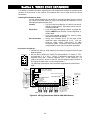
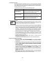
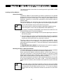
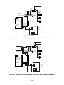
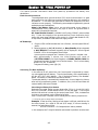
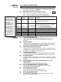
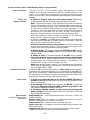
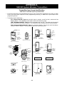
RECOMMENDATIONS FOR PROPER PROTECTION
The Following Recommendations For The Location Of Fire And Burglary Detection
Devices Help Provide Proper Coverage For The Protected Premises.
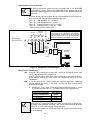
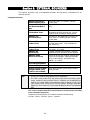
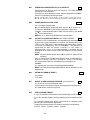
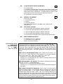
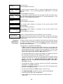
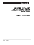
Recommendations For Smoke And Heat Detectors
With regard to the number and placement of smoke/heat detectors, we subscribe to the
recommendations contained in the National Fire Protection Association's (NFPA) Standard #72
noted below.
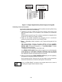
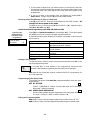
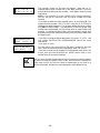
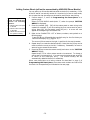
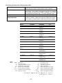
Early warning fire detection is best achieved by the installation of fire detection equipment in all
rooms and areas of the household as follows: For minimum protection a smoke detector should be
installed outside of each separate sleeping area, and on each additional floor of a multi-floor
family living unit, including basements. The installation of smoke detectors in kitchens, attics
(finished or unfinished), or in garages is not normally recommended.
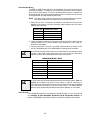
For additional protection the NFPA recommends that you install heat or smoke detectors in the
living room, dining room, bedroom(s), kitchen, hallway(s), attic, furnace room, utility and storage
rooms, basements and attached garages.
In addition, we recommend the following:
• Install a smoke detector inside every bedroom where a smoker sleeps.
• Install a smoke detector inside every bedroom where someone sleeps with the door partly or
completely closed. Smoke could be blocked by the closed door. Also, an alarm in the hallway
outside may not wake up the sleeper if the door is closed.
• Install a smoke detector inside bedrooms where electrical appliances (such as portable
heaters, air conditioners or humidifiers) are used.
• Install a smoke detector at both ends of a hallway if the hallway is more than 40 feet (12
meters) long.
• Install smoke detectors in any room where an alarm control is located, or in any room where
alarm control connections to an AC source or phone lines are made. If detectors are not so
located, a fire within the room could prevent the control from reporting a fire or an intrusion.
THIS CONTROL COMPLIES WITH NFPA REQUIREMENTS FOR TEMPORAL PULSE
SOUNDING OF FIRE NOTIFICATION APPLIANCES.
✪
KITCHEN
▲
DINING
✪
✪
BEDROOM BEDROOM
✪
TV ROOM
▲
KITCHEN
✪
DINING
LIVING ROOM
■
■
✪
✪
LIVING ROOM
BEDROOM
■
✪
B
BEDROOM
✪
▲
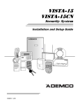
■ Smoke Detectors for Minimum
✪ Smoke Detectors for Additiona
▲ Heat-Activated Detectors
■
BEDROOM
✪
■
✪
BEDROOM
TO
BR
BEDROOM
Recommendations For Proper Intrusion Protection
For proper intrusion coverage, sensors should be located at every possible point of entry to a home or
commercial premises. This would include any skylights that may be present, and the upper windows
in a multi-level building.
In addition, we recommend that radio backup be used in a security system so that alarm signals can
still be sent to the alarm monitoring station in the event that the telephone lines are out of order
(alarm signals are normally sent over the phone lines, if connected to an alarm monitoring station).
–2–
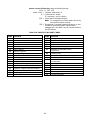
TABLE OF CONTENTS
Section 1.
GENERAL DESCRIPTION .................................................................................................. . 7
Section 2.
INSTALLING THE CONTROL............................................................................................ . 10
Mounting the Cabinet ....................................................................................................... . 10
Installing the Lock (if used) ............................................................................................. . 10
Mounting the Control's Circuit Board Alone in the Cabinet............................................ 11
Mounting Control and RF Receiver Circuit Boards Together in the Cabinet................. 11
Standard Phone Line Connections ................................................................................... . 12
Wiring the AC Transformer ............................................................................................... 12
Installing the Back-Up Battery ........................................................................................ . 13
Earth Ground Connections ................................................................................................ 13
Section 3.
INSTALLING REMOTE KEYPADS .................................................................................... . 14
Keypads That May Be Used............................................................................................... 14
Wiring The Keypads.......................................................................................................... . 14
Mounting The Keypads ..................................................................................................... . 15
Using A Supplementary Power Supply To Power Additional Keypads .......................... 15
Preliminary Check-Out Procedure ................................................................................... . 16
Section 4.
BASIC HARD-WIRED ZONES 1–8.................................................................................... . 17
Installing the Hard-Wired Zones ....................................................................................... 17
Common Characteristics For Zones 1–8 ....................................................................... .17
Wiring Burglary and Panic Devices to Zones 1–8 ......................................................... 17
Wiring 2-Wire Smoke Detectors to Zone 1 ..................................................................... 17
“Verify” Operation of 2-Wire Smoke Detectors in Zone 1 .............................................17
Turning Off Fire Alarm Sounding .................................................................................. 18
Wiring 4-Wire Smoke/Combustion Detectors on Zones 2–7.......................................... 18
Wiring 2-Wire Latching Type Glass Break Detectors on Zone 8.................................. 19
Check-Out Procedure for Hard-Wired Zones .................................................................... 20
Section 5.
WIRED ZONE EXPANSION (4219, 4229).......................................................................... . 21
Installing Zone Expansion Units ....................................................................................... 21
Connections and Set-Up................................................................................................. . 21
Check-Out Procedure for Wired Expansion Zones............................................................ 22
Section 6.
WIRELESS ZONE EXPANSION (5800 SYSTEM).............................................................. 23
General Information.......................................................................................................... . 23
Receiver Supervision...................................................................................................... . 23
House Identification ....................................................................................................... . 23
Installing the 5881/5882 RF Receiver .............................................................................. . 23
RF System Installation Advisories ................................................................................ .23
Installation and Set-Up of the 5881/5882 Receiver....................................................... 24
Installing the 5800TM Module ......................................................................................... .25
Mounting the 5800TM Module ....................................................................................... 25
5800TM Wiring Connections ......................................................................................... .25
5800 Series Transmitters .................................................................................................. .25
General............................................................................................................................ . 25
Transmitter Supervision................................................................................................ . 25
Transmitter Input Types ................................................................................................ 26
Transmitter Battery Life ................................................................................................ 26
Using the Transmitter Sniffer Mode ................................................................................ .26
5800 Series Transmitters Table........................................................................................ . 27
Section 7.
RELAY OUTPUTS & POWERLINE CARRIER DEVICES .................................................. 29
Relay/Powerline Carrier Device Basics ............................................................................. 29
Nos. 4204 And 4229 Output Relay Modules ..................................................................... 29
4204/4229 Setup.......................................................................................................... . 29
Powerline Carrier Devices................................................................................................. . 30
Wiring Connections..................................................................................................... . 31
–3–
Section 8.
4285 & 4286VIP PHONE MODULES ................................................................................ .32
Installing the Phone Module............................................................................................. . 32
General Information ....................................................................................................... . 32
Mounting The Phone Module ........................................................................................ . 32
Phone Module Wiring..................................................................................................... . 33
Caller ID Units ............................................................................................................... .33
Checking the Operation of the 4285 or 4286 Phone Module............................................ 35
Section 9.
EXTERNAL SOUNDERS.................................................................................................... . 36
Compatible Sounders......................................................................................................... . 36
Sounder Connections ......................................................................................................... . 37
Testing the Sounder .......................................................................................................... . 37
Section 10.
LONG RANGE RADIO ....................................................................................................... . 38
General Information.......................................................................................................... . 38
Connection ......................................................................................................................... . 38
Section 11.
REMOTE KEYSWITCH ...................................................................................................... . 39
Installing the Keyswitch .................................................................................................. .39
Remote Keyswitch Connections...................................................................................... 39
Programming for the Remote Keyswitch .......................................................................... 41
Keyswitch Operation...................................................................................................... . 42
Section 12.
AUDIO ALARM VERIFICATION (AAV) UNIT ..................................................................... 43
General Information.......................................................................................................... . 43
Wiring Connections ........................................................................................................... .43
Section 13.
FINAL POWER UP ............................................................................................................. . 45
Earth Ground Connections ................................................................................................ 45
Connecting the Back-Up Battery....................................................................................... 45
Calculating the Battery Size Needed ............................................................................. 45
Making the Battery Connections................................................................................... . 46
Auxiliary Device Current Draw Worksheet ..................................................................... . 46
Section 14.
MECHANICS OF PROGRAMMING ................................................................................... . 47
General Programming Information................................................................................... 47
Entering Program Mode.................................................................................................... . 47
Programming a Data Field................................................................................................ . 47
Reviewing a Data Field/Erasing an Entry in a Data Field .............................................. 48
Interactive Mode Programming ( ✱56, ✱80, ✱82, and ✱83) .............................................. 48
Loading Factory Defaults .................................................................................................. .48
Programming System Setup Fields ................................................................................... 48
Exiting the Programming Mode ....................................................................................... . 48
Section 15.
ZONE RESPONSE TYPE DEFINITIONS ........................................................................... . 49
Section 16.
DATA FIELD DESCRIPTIONS............................................................................................ 51
Section 17.
ZONE PROGRAMMING ( ✱56 Menu Mode) ...................................................................... . 61
Section 18.
OUTPUT DEVICES ( ✱80 Menu Mode).............................................................................. . 65
Section 19.
ZONE LISTS ( ✱81 Menu Mode) ........................................................................................ . 69
Section 20.
ALPHA DESCRIPTOR PROGRAMMING ( ✱82 Menu Mode) ............................................ 70
Zone Descriptors ................................................................................................................ . 70
Programming Zone Descriptors (program Menu Mode ✱82)........................................... 70
Adding Custom Words....................................................................................................... . 73
Alpha Vocabulary List (For Entering Zone Descriptors) .................................................74
Character (ASCII) Chart ................................................................................................... . 74
Section 21.
USING SEQUENTIAL MODE ( ✱83 Menu Mode) .............................................................. 75
Section 22.
REMOTE PROGRAMMING AND CONTROL (DOWNLOADING) ...................................... 78
General Information.......................................................................................................... . 78
Equipment Required ......................................................................................................... . 78
Initial Download ................................................................................................................ . 78
–4–
Remote Programming Information................................................................................... . 79
Remote Programming Advisory Notes .............................................................................. 79
Section 23.
SYSTEM COMMUNICATION ............................................................................................ . 80
Report Code Formats......................................................................................................... . 80
Table of Contact ID Codes................................................................................................. . 82
Section 24.
SYSTEM OPERATION ....................................................................................................... . 83
Security Codes ................................................................................................................... . 83
Keypad Functions.............................................................................................................. . 84
Trouble Conditions ............................................................................................................ . 86
Section 25.
TESTING THE SYSTEM..................................................................................................... . 87
Test Procedure ................................................................................................................... . 87
To the Installer .................................................................................................................. . 88
Section 26.
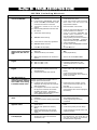
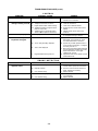
TROUBLESHOOTING GUIDE ............................................................................................ 89
Contacting Technical Support In The Event Of Problems ............................................... 91
REGULATORY AGENCY STATEMENTS .......................................................................... 92
Section 27.
SPECIFICATIONS & ACCESSORIES ............................................................................... . 93
Specifications ..................................................................................................................... . 93
Accessories (Compatible Devices) ...................................................................................... 95
APPENDIX A. 5800 RF System Wireless Transmitters, Input Loop Identification Diagrams............ 96
Index.......................................................................................................................................................... . 97
Limitations Of This Alarm System ...................................................................................................... . 102
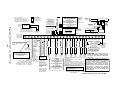
Summary Of Connections .................................................................................................................... . 103
Limited Warranty ...................................................................................................................... . Back Cover
Programming Form ........................................................................................................................... . Insert
LIST OF FIGURES
Figure 1. Installing the Cabinet Lock ............................................................... 10
Figure 2. Mounting The PC Board .................................................................... 11
Figure 3. Mounting the PC Board & RF Receiver Together in the Cabinet ... 11
Figure 4. Telephone Line Connections .............................................................. 12
Figure 5. Connection of 4300 Transformer to the Control Board .................... 13
Figure 6. Keypad Connections to the Control Board........................................ 15
Figure 7. Using a Supplementary Power Supply .............................................16
Figure 8. 2-Wire Smoke Detector Connected to Zone 1 ....................................18
Figure 9. 4-Wire Smoke Detector Connections (Zones 2–7) ............................. 18
Figure 10. Glass Break Detector Connections to Zone 8 ....................................19
Figure 11. Wiring Connection, 4219 & 4229 (4229 shown) ................................ 21
Figure 12. 5881/5882 RF Receiver (cover removed) ........................................... 24
Figure 13. 4229 Connections To Control............................................................. 30
Figure 14. 4204 Connections To Control............................................................. 30
Figure 15. 4300 Transformer Wiring Connections .............................................31
Figure 16. 4285/4286 Phone Module Wiring Connections ................................. 34
Figure 17. Typical Sounder Wiring ..................................................................... 37
Figure 18. Long Range Radio Connections ........................................................ 38
Figure 19A. Keyswitch Wiring (4300 Interface Transformer not used) .............. 40
Figure 19B. Keyswitch Wiring (4300 Interface Transformer also used)............. 40
Figure 20. Connection of AAV Unit When Not Using a 4285 Phone Module .. 44
Figure 21. Connection of AAV Unit When Also Using a 4285 Phone Module . 44
Figure 22. AM100 Summary of Connections .................................................. 103
–5–
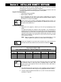
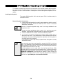
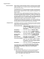
CONVENTIONS USED IN THIS MANUAL
MAIN SECTION TITLES ARE SHOWN IN REVERSE TYPE
Before you begin using this manual, it is important that you understand the
meaning of the following symbols (icons).
UL
These notes include specific information which must be followed if you are
installing this system for a UL Listed application.
These notes include information that you should be aware of before continuing
with the installation, and which, if not observed, could result in operational
difficulties.
This symbol indicates a critical note that could seriously affect the operation of
the system, or could cause damage to the system. Please read each warning
carefully. This symbol also denotes warnings about physical harm to the
installer.
✱20 INSTALLER CODE
In the text of this manual, basic programming data fields are indicated by a
“star” [✱] followed by the data field number (and its title in many cases).
Enter Zn Num.
(00 = Quit)
01
In the text of this manual, interactive programming prompts
are shown in a double-line box (e.g., Menu Mode ✱56 for Zone
Programming).
PRODUCT MODEL NUMBERS: Unless noted otherwise, references to specific
model numbers represent Ademco products.
Whenever it becomes necessary to disconnect power in order to add a module
or keypad, always disconnect the battery and then the AC transformer in that
order. After installation has been completed, connect the AC transformer first
followed by connection of the battery.
–6–
Section 1. GENERAL DESCRIPTION
The AM100 is a security system control that supports up to 38 zones, using basic hard-wired,
wired expansion, and/or wireless zones, plus 3 keypad activated zones.
Basic Hardwired Zones
Provides 8 basic hardwired zones having the following characteristics:
• EOLR supervision supporting N.O. or N.C. sensors
• Programmable response time (10, 350, or 700 milliseconds)
• Up to sixteen 2-wire smoke detectors on zone 1
• 4-wire smoke or heat detectors on zones 2 through 7 (as many as can be
powered from AUX power on the control)
• Up to fifty 2-wire latching type glassbreak detectors on zone 8 with
auto reset
Optional Expansion Zones (up to 30 total, wired and wireless)
Wired Expansion:
Supports up to 8 additional wired zones using a 4219 expansion module or
4229 expansion/relay module.
These zones have the following
characteristics:
• EOLR supervision supporting N.O. or N.C. sensors
• 300–500 msec normal response with an option for fast (10–15 msec)
response on loop A (first expansion zone)
Wireless Expansion:
Supports up to 30 wireless zones (less if using wired expansion zones).
• Requires the use of a 5881(5882 in Canada) type RF Receiver, as
indicated below
Receiver Model
No. of Zones
5881L/5882L
Up to 8
5881M/5882M
Up to 16
5881H/5882H
Up to 30
• Requires the use of 5800 series wireless transmitters
Remote Keypads
Up to 8 of any of the following keypads may be used in the installation:
Fixed-Word Keypad: AM6128
Alpha Keypad: AM6139 (2-line alphanumeric display)
For programming from a keypad, a AM6139 2-line Alpha keypad must be
connected, but need not remain in the system after programming has been
completed.
–7–
Security Codes
•
•
•
•
•
One installer code for entire system (user 1)
One Master code for entire system (user 2)
12 secondary user codes (users 3–14)
One baby-sitter code (user 15)
One duress code (user 16)
Baby-sitter Code: A special code that can only be used to disarm the system if
that particular code (or the installer code) was used to arm it.
Duress Code: An emergency code which, when entered by any user to disarm
or arm the system, will send a silent duress message to the central station.
Keypad Panic Keys
• Up to 3 programmable panic key functions are provided.
• Designated as Zones 95, 96, 99
• Activated by wired & wireless keypads
• Distinguished by subscriber ID number
Zone Monitor Feature
• The control will sense a high resistance in the loops on hard-wired
zones 2–8 if it is present, and will display a trouble message (rather
than an alarm) for the affected zone when the system is in the disarmed
mode. This feature also prevents the system from being armed while
this high resistance condition exists.
Exit Error False Alarm Prevention Feature
• Enables the system to determine the difference between an actual
alarm and an alarm caused by leaving an Entry/Exit or Interior zone
open after the exit delay expires. If not disarmed in time, an alarm will
sound and an “Exit Error” report sent to the central station.
• An Exit Alarm condition will also occur if an Entry/Exit or Interior zone
re-opens within 2 minutes after the end of an exit delay.
Optional Output Relays and Powerline Carrier Devices (X-10 type)
• Up to 4 relays using one 4204 Relay Module
• Up to 2 relays using one 4229 Zone/Relay Module
• Up to 8 Powerline Carrier devices (you must subtract the number of
relay outputs actually used by the 4204 or 4229 modules, if used)
• Actions programmable to respond to zone activity or manual keypad
entries
Powerline Carrier devices require the use of optional 4300 transformer module
instead of the supplied 1321 AC transformer.
Optional Phone Module
• Supports the Ademco 4285/4286 Phone Module
• Provides access to the system via on premises or off-premises phones
for arming, disarming, etc., plus control of relay outputs and Powerline
Carrier devices.
Paging Feature
• If programmed, the paging feature permits up to 16-digits to be sent to
a pager for user-determined messaging, followed by a system
generated 7-digit condition code which indicates the type of condition
that has occurred and the user number or zone number of occurrence.
Audio Alarm Verification Option
• Provides a programmable Audio Alarm Verification (AAV) option which
can be used in conjunction with an output relay to permit voice dialog
between an operator at the central station and a person at the premises.
• Requires the use of optional AAV unit, such as Eagle model 1241.
UL
The AAV option may not be used in UL installations.
–8–
Optional Long Range Radio
• Allows all messages that have been programmed to go to the primary
telephone number to be reported additionally to a 7720PLUS or 7820
radio. Check availability of these models.
Built-in Telephone Line Monitoring Option
• The telephone line voltage can be monitored to supervise the phone line
connection. The panel must be connected to a proper earth
ground or you will get a false line cut indication if this feature
is enabled.
• The loss of the line can optionally cause a local display, or a display and
trouble sound.
Event Logging
• Event Logging feature keeps a record of selected events in a history log
(up to 48 events). All control and readout from the log is done via
Ademco V-Link software only.
Alarm Output
• Provides a 12VDC, 2 AMP output that can drive the compatible
sounders listed in the EXTERNAL SOUNDERS section ( assumes a fully
charged battery is connected) .
• Steady output for Burglary/Panic, or temporal pulse output (3 pulses –
pause – 3 pulses – pause – 3 pulses. . .) for Fire.
• Uses current limiting circuitry for protection.
Auxiliary Power Output
• Provides 12VDC, 600 mA maximum. Uses current limiting circuitry for
protection.
• This output interrupts for smoke detector reset if 4-wire smoke
detectors are used.
Programming
• Programmed options are stored in electrically erasable, non-v olatile
EEPROM memory (information can be reprogrammed at any time and
will not be lost in the event of a power loss).
• The system can be uploaded, downloaded, or controlled via an IBM
compatible computer, V-Link software and a HAYES modem specified
by Ademco.
Keypad programming consists of:
• Data field programming
• Interactive (menu) mode programming
Communication Formats Supported
• Ademco Low Speed (Standard or Expanded)
• Sescoa/Radionics (Standard or Expanded)
• Ademco Express
• Ademco Contact ID
Zone Descriptors
You can assign Alpha descriptors to all zones (useful only when using
Alpha keypads and/or the 4285/4286 Phone Module).
AC Power Supply
Uses 1321, 110VAC plug-in transformer with 16.5VAC 25VA output,
unless Powerline Carrier devices (ex. X-10 type) are used, in which case a
4300 transformer module must be used.
Back-Up Battery
• Rechargeable (Gel type) 12VDC, 4AH minimum.
–9–
Section 2. INSTALLING THE CONTROL
This section provides instructions for mounting the control cabinet and
installing the cabinet lock (if used). Also included in this section are
instructions for the following:
• Installing the main PC board
• Mounting the 5881 (5882 in Canada) RF Receiver board in the cabinet (if
used)
• Standard phone line connections
• Installing the back-up battery in the cabinet
• Connecting the AC transformer
• Making earth ground connections
Mounting the Cabinet
Mount the control cabinet to a sturdy wall using fasteners or anchors (not
supplied), in a clean, dry area which is not readily accessible to the general
public. Four mounting holes are provided at the back of the cabinet.
If an RF Receiver is being used and you intend to mount its PC board within
the cabinet, note the following:
• Do not mount the cabinet on or near metal objects. This will decrease
RF range and/or block RF transmissions from wireless transmitters.
• Do not locate the cabinet in an area of high RF interference (revealed by
frequent or prolonged lighting of the LED in the receiver after it is
operational (random flicker is OK).
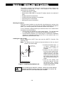
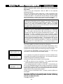
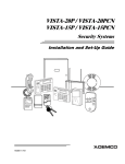
Installing the Lock (if used)
Use an Ademco No. N6277 Cam Lock and No. N6277–1 Push-On Clip
(Retainer Clip).
Note: The cabinet can be closed and secured without a lock by using 2
screws in the cover's edge.
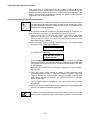
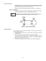
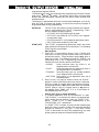
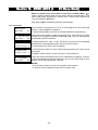
1. Remove the cabinet door. It
RETAINER CLIP
is easily removable for
(NOTE POSITION)
servicing and is easily reinstalled.
2. Remove the lock knockout
LOCKED
RETAINER
from the control cabinet door.
SLOTS
RETAINER
Insert the key into the lock.
CLIP
Position the lock in the hole
making certain that the latch
will make contact with the
UNLOCKED
latch bracket when the door is
closed.
3. Hold the lock steady, and
CABINET DOOR BOTTOM
insert the retainer clip into
the retainer slots. Position
the clip as illustrated in order
Figure 1. Installing The Cabinet Lock
to permit easy removal.
Before installing the cabinet's contents, remove the metal cabinet
knockouts required for wiring entry. Do not attempt to remove the
knockouts after the circuit board has been installed.
–10–
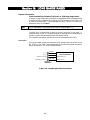
Mounting The Control's Circuit Board Alone in The Cabinet (Fig. 2)
1. Hang two short Black mounting clips (provided) on the raised cabinet
tabs (see Detail B in Fig. 2).
2. Insert the top of the circuit board into the slots at the top of the cabinet.
Make sure that the board rests on the correct row (see Detail A ).
3. Swing the base of the board into the mounting clips and secure the board
to the cabinet with the accompanying screws (see Detail B in Fig. 2).
Figure 2. Mounting The PC Board
Mounting Control and RF Receiver Circuit Boards Together, in the Cabinet
1. Hang two short (black) mounting clips (provided with receiver) on the
raised cabinet tabs, as shown in Detail B in Figure 3.
2. Insert the top of the receiver board (removed from its own case as
described in its instructions) into the slots at the top of the cabinet, as
shown in Detail A in Figure 3. Make sure that the board rests on the
correct row of tabs, as shown.
3. Swing the base of the board into the mounting clips and secure it to the
cabinet with the accompanying screws (see Detail B in Fig. 3).
4. Insert the top of the control's board into the slot in the clips and position
two long (red) clips at the lower edge of the board (see Detail C).
5. Swing this board into place and secure it with two additional screws.
6. Insert grounding lugs (supplied with the receiver) through the top of the
cabinet into the left-hand terminals of the antenna blocks (at the upper
edge of the receiver board) and secure them to the cabinet top with the
screws provided, as shown in Detail D.
7. Insert the receiver's antennas through the top of the cabinet, into the
blocks' right-hand terminals, and tighten the screws.
8. Refer to the WIRELESS ZONE EXPANSION section for setup and wiring
of the receiver.
Figure 3. Mounting The PC Board And RF Receiver
Together In The Cabinet
–11–
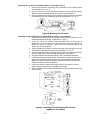
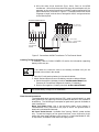
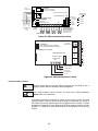
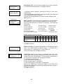
Standard Phone Line Connections
The wiring connections shown here are not applicable if the 4285/4286
Phone Module is used. Refer to the 4285/4286 Phone Module section for
information regarding phone line connections, which are different than those
shown here.
Incoming
Telco Line
{
{
26
21
27
22
28
23
29
24
25
30
➡
INCOMING TELCO LINE
TIP
RING
RED (RING)
GREEN (TIP)
GRAY (RING)
EARTH GROUND
DIRECT
CONNECT
CORD
▲
BROWN (TIP)
▲
TERMINALS
ON CONTROL
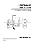
IMPORTANT!
IF THE PANEL IS NOT CONNECTED TO A PROPER
EARTH GROUND, YOU MAY GET FALSE TELEPHONE
LINE CUT INDICATIONS (IF THE TELEPHONE LINE
MONITOR HAS BEEN PROGRAMMED IN FIELD 92).
➧
▲
Handset
GROUND
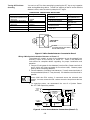
Incoming phone line and handset wiring is connected to the main terminal
block (via a RJ31X jack) as follows (also see Figure 4):
Term. 21: Local Handset (TIP – Brown*)
Term. 22: Local Handset (RING – Gray*)
Term. 23: Incoming Phone Line (TIP – Green*)
Term. 24: Incoming Phone Line (RING – Red*)
* Colors of wires in Direct Connect Cord.
TIP
RJ31X
JACK RING
PREMISES
PHONES
▲
PLUG
Figure 4. Telephone Line Connections
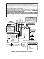
Wiring The AC Transformer
1321 Wire the 1321 transformer to terminals 1 and 2 on the control board. See
wiring table below for wire gauge to use.
Caution must be taken when wiring the transformer to the control panel to
guard against blowing the fuse inside the transformer (the fuse is nonreplaceable).
4300 If you are going to use a 4300 transformer interface (required if Powerline
Carrier devices are going to be used), connect the 4300 transformer’s
terminals as follows:
a. Terminals 1, 3 (AC), and 2 (Ground) to control board terminals 1, 2, and
25, respectively (see Figure 5). See table below for wire gauge to use.
WIRING TABLE
Distance of Transformer
Wire Gauge
From the Control Panel
To Use
Up to 50 feet
# 20
50–100 feet
# 18
100-250 feet
# 16
Wiring to the AC Transformer must not exceed 250 feet using 16 gauge wire.
The voltage reading between terminals 1 and 2 of the control must not fall below
16.5VAC or an "AC LOSS" message will be displayed.
Do not plug the transformer into the AC outlet until you are instructed to do so
later in the manual.
–12–
b. Wire the other three terminals (Sync, Data, Com) on the 4300
transformer. Wires from these terminals must be connected to a 9-pin
connector on the control board (using a 4142TR cable supplied with the
4300 transformer), as shown in Figure 5. These particular wires can be
24 gauge or larger, and can be run along with the AC and ground wires
to the control panel.
6
8
9
9-PIN CONNECTOR
ON CONTROL BOARD
BLACK
5
7
BLUE
4
6
BROWN
Sync Data Com
5
GREEN
3
4
RED
2
3
WHITE
1
2
GRAY
Earth
AC Ground AC
VIOLET
1
YELLOW
4300 TRANSFORMER/INTERFACE
4142TR CABLE
1
25
THESE WIRES (7, 8, 9) NOT USED,
UNLESS 4146 KEYSWITCH
IS ALSO USED
2
TERMINALS
ON CONTROL
BOARD
Figure 5. Connections of 4300 Transformer To The Control Board
Installing The Back-Up Battery
If necessary, refer to FINAL POWER UP section for information regarding
battery size to use, etc.
Do not attach the connector cable to the battery terminals until you are
instructed to do so later in the manual.
1. Place the 12-volt back-up battery in the control cabinet.
2. Attach Red and Black wires on the battery connector cable as follows:
a. Red to the positive (+) battery terminal on the control board (see
Summary of Connections Diagram for location, if necessary).
b. Black to the negative (–) battery terminal on the control board.
UL
Use a 4AH battery or larger for UL installations.
Earth Ground Connections
The designated earth ground terminal (25), must be terminated in a good
earth ground for the lightning transient protective devices in this product to
be effective. The following are examples of good earth grounds available at
most installations:
Metal Cold Water Pipe: Use a non-corrosive metal strap (copper is
recommended) firmly secured to the pipe to which the ground lead is
electrically connected and secured.
AC Power Outlet Ground: Available from 3-prong, 120VAC, power outlets
only. To test the integrity of the ground terminal, use a three-wire circuit
tester with neon lamp indicators, such as the UL-Listed Ideal Model 61–035,
or equivalent, available at most electrical supply stores.
–13–
Section 3. INSTALLING REMOTE KEYPADS
This section lists the wired keypads that may be used and provides
instructions for wiring and mounting the keypads.
A preliminary check-out procedure is also provided to ensure that the
connected keypads are functioning properly in the system.
Keypads That May Be Used
• Fixed-Word Display: AM6128
• Alpha Display: AM6139
• Up to 8 keypads may be used in the system, independent of auxiliary
power considerations (you may need to use an auxiliary power supply if
the 600mA aux. output is exceeded)
If you are going to use a 4285 or 4286 Phone Module with this system, you
MUST use an addressable keypad (AM6128 or AM6139) set to the nonaddressable mode (address 31).
Wiring To The Keypads
1. Determine wire gauge by referring to the wiring length/gauge chart
below.
For devices (Keypads, RF Receivers, Zone Expander , etc.) connected to a
single 4-wire run, determine the current drawn by all units connected to
the single wire run, then refer to the Wiring Run chart to determine the
maximum wire length that can be safely used for each wire size. Current
draw for all devices can be found in the SPECIFICATIONS AND
ACCESSORIES section.
Note: Refer to “Auxiliary Device Current Draw Worksheet” in the
FINAL POWER UP section for current draw for all keypads.
Maximum wire lengths for any device that is wired to the control can also be
determined from the chart, based on the current draw of that device alone.
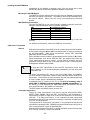
Wiring Run Chart For Devices* Drawing Aux Power From
The Control (+12V & –12V)
TOTAL CURRENT DRAWN BY ALL DEVICES CONNECTED TO A SINGLE WIRE RUN
Wire Size
50 mA or less
100 mA
300 mA
500 mA
#22
#20
#18
#16
500 ft (152m)
750 ft (228.6m)
1300 ft (396m)
1500 ft (457m)
250 ft (76m)
380 ft (116m)
650 ft (198m)
1000 ft (305m)
80 ft (24m)
130 ft (39.6m)
220 ft (67m)
330 ft (100.5m)
50 ft (15m)
80 ft (24m)
130 ft (39.6m)
200 ft (70m)
600 mA
42 ft (13m)
67 ft (20.4m)
115 ft (35m)
170 ft (52m)
* Includes Keypads, RF Receivers, Zone Expander/Relay Units, or 4285/4286 Phone Module.
The length of all wire runs must not exceed 1500 feet (457m) when unshielded
quad conductor cable is used (750 feet if shielded cable is used). This
restriction is due to the capacitive effect on the data lines when quad cable or
shielded cable is used.
2.
Run field wiring from the control to the keypads (using standard 4conductor twisted wire cable using the wire gauge determined in step 1).
3.
Connect remote Keypads to terminals 4, 5, 6, and 7 on the control board,
as shown in Figure 6.
–14–
4
BLACK
RED
5
6
GREEN
KEYPAD
YELLOW
7
CONTROL
TERMINALS
Figure 6. Keypad Connections To The Control Board
Mounting the Keypads
1. Make sure addressable type keypads (AM6128 and AM6139) are set to
non-addressable mode (address 31), which is the factory default setting.
Refer to the instructions provided with the keypad for address setting
procedure.
2.
Mount the keypads at a height that is convenient for the user. Refer to
the instructions provided with the keypad for mounting procedure.
You can either surface mount or flush mount keypads (using an
appropriate Trim Ring Kit: AM6139TRK). Refer to the mounting
instructions and template included with the keypad and/or trim ring kit
for specific information.
Using a Supplementary Power Supply to Power Additional Keypads
The control provides 600mA for powering keypads (up to a maximum of 8)
and other devices from the auxiliary power output. The backup battery will
supply power to these keypads in the event that AC power is lost.
When the control’s auxiliary power load for all devices exceeds 600 mA, you
can power additional keypads from a regulated, 12VDC power supply (e.g.,
487–12 supplies 12V, 250mA; 488–12 supplies 12V, 500mA). Use a UL
Listed, battery-backed supply for UL installations.
The 487–12/488–12 power supplies have a backup battery which can power
these keypads in the event of AC power loss.
Keypads powered from supplies which do not have a backup battery will not
function when AC power is lost. Therefore, be sure to power at least one
keypad from the Control's auxiliary power output.
Connect the additional keypads as shown in Figure 7, using the keypad wire
colors shown. Be sure to observe the current ratings for the power supply
used.
Make connections directly to the screw terminals as shown in Figure 7. Make no
connection to the keypad blue wire (if present).
Be sure to connect the negative (–) terminal on the Power Supply unit to
terminal 4 (AUX – ) on the control.
–15–
SUPPLEMENTARY
POWER SUPPLY
+
CONTROL
TERMINAL STRIP
–
TO KEYPAD YEL WIRE
TO KEYPAD GRN WIRE
TO KEYPAD BLK WIRE
IMPORTANT:
MAKE THESE
CONNECTIONS
DIRECTLY TO
SCREW
TERMINALS AS
SHOWN.
TO KEYPAD RED WIRE
TO KEYPAD YEL WIRE
TO KEYPAD GRN WIRE
TO KEYPAD BLK WIRE
TO KEYPAD RED WIRE
AUX AUX. DATA DATA
–
+
IN
OUT
4
5
6
7
Figure 7. Using A Supplementary Power Supply For Keypads
Preliminary Check-out Procedure
If you want to check that the system is working before connecting field wiring
from zones and devices, do the following:
1. Temporarily connect a 2000 ohm end-of-line resistor across each of the
basic hard-wire zones 1–8, as shown in the Summary of Connections
diagram.
Without actual zone wiring or EOL resistors connected, the keypads of the
system will not display the “Ready” message.
2. Power up the system temporarily by plugging the AC transformer
(previously wired to the control) into a 120VAC outlet.
3. B u s y – S t a n d b y (Alpha keypads) or dI (Fixed-word keypads) will be
displayed.
After approximately 1 minute*, the green “READY” LED (or “POWER”
LED on some types of keypads) should light, and the words READY
ENTER CODE (Fixed-word keypads), or ** SYSTEM READY** (Alpha
keypads) should be displayed.
* To bypass the 1-minute delay, press [#] plus 0.
If the READY ENTER CODE display does not appear on any of the keypads
in the system, or a “Not Ready” message is displayed, check the keypad
wiring connections, and make sure each of the 8 basic hard-wired zones
has a 2000 ohm resistor connected across its terminals.
4. When you get the proper READY ENTER CODE displays on the keypad(s),
the system is functioning properly at this point.
Do not remove the EOL resistors until you are ready to make connections
to the hard-wired zones, to allow for testing later in the manual.
If an OC or OPEN CIRCUIT is present on the keypad, data from the control is
not reaching the keypad. Please check the wiring.
–16–
Section 4. BASIC HARD-WIRED ZONES 1–8
This section provides general information for the hard-wired zones in the system, plus
specific instructions for installing 2-wire smoke detectors, 4-wire smoke/combustion
detectors, and 2-wire latching type glass break detectors.
Installing the Hard-Wired Zones
Common Characteristics for Zones 1–8
• EOLR supervised zones supporting both open circuit and closed circuit
devices
• As many 4-wire smoke detectors as can be powered from Aux Power on the
control (zones 2–7)
• Programmable for 10, 350, or 700 msec response
• 350 msec (default) should be used for most standard contacts. For
vibration type contacts, 10 msec is more suitable
Wiring Burglary and Panic Devices To Zones 1–8
1. Connect sensors/contacts to the hard-wired zone terminals (8 through 20).
See the Summary of Connections diagram .
2. Connect closed circuit devices in series in the high (+) side of the loop. The
EOL resistor must be connected in series with the devices, following the
last device. See the Summary of Connections diagram.
3. Connect open circuit devices in parallel across the loop. The 2,000 ohm
EOLR must be connected across the loop wires at the last device.
If the EOLR is not at the end of the loop, the zone will not be properly
supervised, and the system may not respond to an open circuit on the zone.
High Resistance Supervision on Hard-Wired Zones 2–8
• Special supervision in the control senses high resistance on hard-wired
zone loops 2–8, causing a warning “CHECK” display with the affected zone
number to occur when the system is in the disarmed state. The system
cannot be armed when this display is present. If the system is in the
armed state when the high resistance condition occurs, no display will
take place until the system is disarmed.
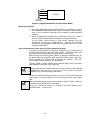
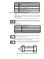
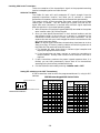
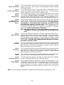
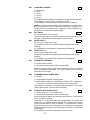
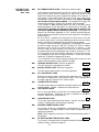
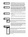
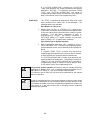
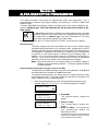
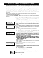
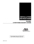
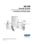
Wiring 2-Wire Smoke Detectors To Zone 1
1. Connect 2-wire smoke detectors across zone 1 terminals 8 (+) and 9 (–).
Observe proper polarity when connecting the detectors.
2. If an EOL resistor is presently connected across zone 1 terminals, remove
it. The EOL resistor must be connected across the loop wires at
the last detector.
UL
In UL installations, only zone 1 may be used as a Fire zone. In addition, an
Ademco Model 610–7 must be used as an End-of-Line resistor at the last
detector.
The alarm current provided by zone 1 will support only one smoke detector in
the alarmed state.
“Verify” Operation of
2-Wire Smoke Detectors
in Zone 1
The control panel will “verify” any alarm by resetting the smoke detectors
after the first alarm trigger, and then waiting 90 seconds for a second alarm
trigger. If the smoke detector or thermostat does not trigger again, the
control will disregard the first trigger, and no alarm signal will occur. This
feature eliminates false alarms due to electrical or physical transients.
This feature is available only on units that report to the downloader as Rev
4 or higher.
–17–
Turning Off Fire Alarm
Sounding
You can turn off Fire alarm sounding by pressing the OFF key on any keypad or
other arming/disarming device. To clear the "memory of alarm" and to reset the
detector’s alarm, enter the security code plus OFF again.
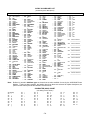
COMPATIBLE 2-WIRE SMOKE DETECTORS
Detector Type
Photoelectric w/heat sensor,
direct wire
Photoelectric, direct wire
Photoelectric w/heat sensor,
direct wire
Photoelectric
Photoelectric w/heat sensor
Ionization, direct wire
System Sensor
Model No.
2300TB
2400
Detector Type
Ionization
Photoelectric duct detector
Ionization duct detect
2400TH
2451 w/B401B base
2451TH w/B401B base
1400
Low-profile, Photoelectric,
w/135°F thermal
Low-profile, Ionization type,
direct wire
System Sensor
Model No.
1451 w/B401B base
2451 w/DH400 base
1451DH
w/DH400 base
2100T
1100
@@@@@@@@e?
@@@@@@@@e?@@@@@@@@?e@@@@@@@@e?@@@@@@@@?e@@@@@@@@e?@@@@@@@@?e@@@@@@@@e?@@@@@@@@?e@@@@@@@@e?@@@@@@@@?e
@@@@@@@@e?
@@@@@@@@e?@@@@@@@@?e@@@@@@@@e?@@@@@@@@?e@@@@@@@@e?@@@@@@@@?e@@@@@@@@e?@@@@@@@@?e@@@@@@@@e?@@@@@@@@?e@@@@@@@@
@@@@@@@@
@@h?
@@
@@h?
@@
@@h?
@@
@@h?
@@
@@h?
@@
@@h?
@@
@@
@@
@@
@@
@@
@@
@@
@@
@@
@@
@@
@@
@@
@@
@@
@@
+
@@
@@
@@
@@
@@
@@
@@
@@
@@
@@
@@
@@
@@
@@
@@
@@
@@
@@
@@
@@
@@
@@
@@
@@
@@
@@
@@
@@
@@
@@
@@
@@
@@
@@
@@
@@
@@
@@
@@
@@
@@
@@
@@
@@
@@
@@
@@
@@
@@
@@
@@
@@
@@
@@
@@
@@
@@
@@
@@
@@
@@
@@
@@
@@
@@
@@
@@
@@
@@
@@
@@
@@
@@
@@
@@
@@
@@
@@
@@
@@
@@g
@@g
@@g
@@g
@@g
@@g
@@@@@@@@
@@@@@@@@
8
@@
@@
@@
@@
@@
@@
@@
@@
@@
@@
@@
@@
@@
@@
@@
@@
@@
@@
@@
@@
@@
@@
@@
@@
@@
@@
@@
@@
@@
@@
@@
@@
@@
@@
@@
@@
@@
@@
@@
@@
@@
@@
@@
@@
@@
@@
@@
@@
2-WIRE SMOKE
DETECTOR
@@
@@
@@
@@
@@
@@
@@
@@
–
@@
@@
@@
@@
@@
@@
@@
@@
@@
@@
@@
@@
@@
@@
@@
@@
@@
@@
@@
@@
@@
@@
@@
@@
SMOKE
2000 OHMS
EOLR
@@
@@
@@
@@
@@
@@
@@
@@
ZONE 1
@@
@@
@@
@@
@@
@@
@@
@@
@@
@@
@@
@@
@@
@@
@@
@@
9
@@
@@
@@
@@
@@
@@
@@
@@
@@
@@
@@
@@
@@
@@
@@
@@
UL NOTE:
IN UL INSTALLATIONS, ONLY ZONE 1
MAY BE USED FOR FIRE.
@@
@@
@@
@@
@@
@@
@@
@@
?@@
?@@
?@@
?@@
?@@
?@@
?@@@@@@@@?e@@@@@@@@e?@@@@@@@@?e@@@@@@@@e?@@@@@@@@?e@@@@@@@@e?@@@@@@@@?e@@@@@@@@e?@@@@@@@@?e@@@@@@@@
?@@@@@@@@?e@@@@@@@@e?@@@@@@@@?e@@@@@@@@e?@@@@@@@@?e@@@@@@@@e?@@@@@@@@?e@@@@@@@@e?@@@@@@@@?e@@@@@@@@ ?@@@@@@@@
?@@@@@@@@
Figure 8. 2-Wire Smoke Detector Connected to Zone 1
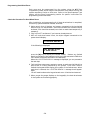
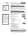
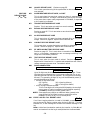
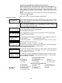
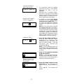
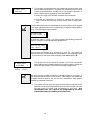
Wiring 4-Wire Smoke/Combustion Detectors on Zones 2–7
The system will support as many 4-wire detectors as can be powered from
Auxiliary Power on the control, on zones 2–7. Refer to the detector’s
instructions for complete details regarding its proper installation and
operation.
1. Connect 12 volt power for the detectors from Auxiliary Power terminals 4
and 5, (which will interrupt power for fire alarm reset). Observe proper
polarity when connecting detectors.
2. Connect detectors (including heat detectors, if used) across terminals of
the zone selected (zones 2–7 may be used). All detectors must be wired in
parallel.
Remove 2000 ohm EOL resistor if connected across the selected zone
terminals. You must connect the EOL resistor across the loop wires at the last
detector.
3. To supervise power, we recommend the use of a System Sensor
No. A77-716B supervisory module.
AUX PWR
OUTPUT
TERMINALS
+
5
-
4
BLK
+
4-WIRE SMOKE
OR COMBUSTION
DETECTORS
-
+
-
–
+
•
VIOLET
•
TO HI SIDE OF
SELECTED
ZONE
•
2000
OHMS
EOLR
+
HEAT
DETECTOR
ZONES 2–7*
TO LO SIDE
OF SELECTED
ZONE
RED
EOL
POWER
SUPERVISION
RELAY
MODULE
A77-716B
-
HEAT
DETECTOR
* IF PROGRAMMED FOR FIRE
Figure 9. 4-wire Smoke Detector Connections (Zones 2–7)
–18–
COMPATIBLE 4-WIRE SMOKE/COMBUSTION DETECTORS
1412
System Sensor, 4-wire ionization products of combustion
detector
2412
System Sensor, 4-wire photoelectric smoke detector
2412TH
System Sensor, 4-wire photoelectric smoke detector
w/135º F (57º C) heat detector
A77–716B System Sensor, EOL relay module (supervisory module for
wired 4-wire fire zone).
2112/24T
System Sensor low-profile 4-wire photoelectric smoke
detector w/135º F (57º C) heat detector
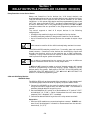
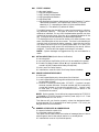
Wiring 2-Wire Latching Glass Break Detectors On Zone 8
Use zone 8 for connection of compatible 2-wire latching-type glass break
detectors.
After an alarm, the first code + OFF turns off the siren and disarms the
system; the second code + OFF clears the memory of alarm and resets the
glassbreak detector.
1. Connect all detectors in parallel across zone 8 (terminals 19 and 20).
Remove 2000 ohm EOL resistor if connected across the selected zone
terminals. You must connect the EOL resistor across the loop wires at the
last detector.
Compatible Glass Break Detectors
Use detectors that meet the following ratings:
Standby Voltage:
Standby Resistance:
Alarm Resistance:
Alarm Current:
Reset Time:
5VDC–13.8VDC
Greater than 20k ohms (equivalent resistance of all
detectors in parallel)
Less than 1.1k ohms (see note below)
2 mA–10 mA
Less than 6 seconds
The IEI 735L series detectors have been tested and found to be compatible
with these ratings. You can use up to fifty IEI 735L detectors, connected in
parallel.
You should note that only one detector in the alarmed state can be supported
by the alarm current provided by zone 8.
You can use detectors which exceed 1.1k ohms in alarm, provided they
maintain a voltage drop in alarm of less than 3.8 volts.
Do not use other N.O. or N.C. contacts when using glass break detectors on
zone 8. Other contacts may prevent proper glass break detector operation.
GLASSBREAK
DETECTOR
ZONE 8
19
(+)
20
(–)
LATCHING TYPE GLASS
BREAK DETECTOR LOOP
2000
OHMS
EOLR
Figure 10. Glass Break Detector Connections To Zone 8
–19–
Programming Hard-Wired Zones
Each zone must be programmed into the system using the ✱56 Zone
Programming mode, which assigns characteristics that define the way the
system responds to faults on that zone. Refer to the Zone Response Type
section and the Zone Programming section for specific instructions on
programming hard-wired zones.
Check-Out Procedure For Hard-Wired Zones
After installation and programming of all hard-wired devices is completed,
the security system should be checked, as follows.
1. Make certain that all devices and sensors connected to the hard-wired
zones are not in a faulted state. Doors and windows with contacts should
be closed, PIRs should be covered (use a cloth to mask them temporarily if
necessary).
2. Plug in the AC Transformer if you have not already done so.
3. With all hard-wired zones intact, the Alpha keypad connected to the
system should display:
* * S Y S T E M RE A D Y * *
If the following is displayed,
N O T RE A D Y - P r e s s ✱
t o sh o w fa u l t s
press the [✱] key to display the faulted zone(s). Restore any faulted
zone(s) as necessary (also make sure that you have connected a 2000 ohm
EOL resistor across the terminals of unused zones).
When the **SYSTEM READY** message is displayed, you can proceed to
the next step.
4. Fault and then restore every contact or sensor on each zone individually to
ensure that it is being monitored by the system. Each time a zone is
faulted, the keypad should display the number of the faulted zone. When
each zone is restored, the **SYSTEM READY** message should appear
again.
You will need to observe the keypad as each zone is faulted and restored.
5. When you get the proper displays on the keypad(s), the hard-wired zones
in the system are functioning properly.
–20–
Section 5. WIRED ZONE EXPANSION
This section provides information regarding the use of expansion modules for expanding the
number of wired zones in the system, the modules that can be used and their wiring
connections.
Installing Zone Expansion Units
You can add an additional 8 wired EOLR zones to the basic control's 8 zones,
for a total of 16 wired zones, by using a No. 4219 Wired Expansion Unit, or
4229 Wired Expansion/Relay Unit.
Location
• You can mount an expansion unit within the control
cabinet if space permits. Otherwise, mount the unit
outside the cabinet.
Supervision
• Units are supervised against removal. Keypads will
display CHECK and zone 09 if a zone expander is
disconnected.
• Units have tamper protection for security when
mounted outside of the cabinet.
Zone Information
• Assign zone numbers 10–17 for the eight wired
expansion loops (designated A to H). You can
program these zones individually (in ✱56
interactive mode). Expansion zones must also be
programmed as input type 2 (AW) when prompted.
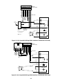
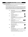
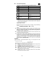
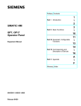
Connections and Set-Up
1. Connect the 4219 or 4229 module to the control's keypad terminals (see
diagram below).
2. Set the 4219 or 4229's DIP switch for device address "1" (switch 2 "OFF"
and switches 3, 4, 5 "ON"). Switch 1 determines expansion zone A's
response time ("ON" = normal response, "OFF" = fast response). For
location of the DIP switch in the unit, see the diagram below (location of
DIP switch for both units is in the same location).
For additional information, see instructions supplied with the 4219 and
4229.
ON
1 2 3 4 5
@@
@@
@@
@@
@@
@@
@@
@@
@@
@@
@@
@@
@@
@@
@@
@@
@@
@@
@@
@@
@@
@@
@@
@@
@@
@@
@@
@@
@@
@@
@@
@@
@@
@@
@@
@@
@@
@@
@@
@@
@@
@@
@@
@@
@@
@@
@@
@@
@@
@@
@@
@@
@@
@@
@@
@@
@@
@@
@@
@@
@@
@@
@@
@@
@@
@@
@@
@@
@@
@@
@@
@@
@@
@@
@@
@@
@@
@@
@@
@@
@@
@@
@@
@@
@@
@@
@@
@@
@@
@@
@@
@@
@@
@@
@@
@@
@@
@@
@@
@@
@@
@@
@@
@@
@@
@@
@@
@@
@@
@@
@@
@@
@@
@@
@@
@@
@@
@@
@@
@@
@@
@@
@@
@@
@@
@@
@@
@@
@@
@@
@@
@@
@@
@@
@@
@@
@@
@@
@@
@@
@@
@@
@@
@@
@@
@@
@@
@@
@@
@@
@@
@@
@@
@@
@@
@@
@@
@@
@@
@@
?@@@@@@@@?e@@@@@@@@e?@@@@@@@@?e@@@@@@@@e?@@@@@@@@?e@@@@@@@@e?@@@@@@@@?e@@@@@@@@
?@@@@@@@@?e@@@@@@@@e?@@@@@@@@?e@@@@@@@@e?@@@@@@@@?e@@@@@@@@e?@@@@@@@@?e@@@@@@@@
?@@
?@@
?@@
?@@
?@@
?@@
?@@@@@@@@
?@@@@@@@@
RELAY
CONNECTOR
RELAY
2
➞
EITHER OR BOTH CAN BE USED
RELAY
1
NO C NC
{
RELAYS
"OFF"
1
2
3
4
5
6
TB1
7
9
8
10
11
12
➞
{
{
RLY
1
4-PIN CONSOLE PLUG
TAMPER JUMPER POSITION
4229 IN CABINET
(NOT TAMPERED)
4229 REMOTE
(TAMPER PROTECTED)
WHT
GRY
VIO
BLK
YEL
ORG
BRN
NO
NC
C
GND
NO
NC
C
RLY
2
TB2
REED
(TAMPER)
SWITCH
1K
ZONES: A
B
C
D
4
➞
}
TERMINALS ON
CONTROL PANEL
➞
➞
▲
}
4229
DIP SWITCH
FOR SETTING ADDRESS
AND ZONE “A” RESPONSE
➞
@@g
@@g
@@g
@@g
@@g
@@g
@@@@@@@@
@@@@@@@@
▲
ON
➞
OFF
@@@@@@@@e?
@@@@@@@@e?@@@@@@@@?e@@@@@@@@e?@@@@@@@@?e@@@@@@@@e?@@@@@@@@?e@@@@@@@@e?@@@@@@@@?e
@@@@@@@@e?
@@@@@@@@e?@@@@@@@@?e@@@@@@@@e?@@@@@@@@?e@@@@@@@@e?@@@@@@@@?e@@@@@@@@e?@@@@@@@@?e@@@@@@@@
@@@@@@@@
@@h?
@@
@@h?
@@
@@h?
@@
@@h?
@@
@@h?
@@
@@h?
@@
E
F
G
4
3
2
3
1
1
2
GRN DATA OUT
TO CONTROL
BLK
(–) GROUND
RED
(+) 12V
YEL DATA IN
FROM
CONTROL
TERMINATE EACH
PROGRAMMED ZONE
WITH 1000 OHM (1K)
END-OF-LINE RESISTOR
(EACH ZONE'S MAX.
LOOP RESISTANCE:
300 OHMS + E.O.L.)
H
Figure 11. Wiring Connections, 4219 & 4229 (4229 shown)
–21–
(TERM 6)
(TERM 4)
(TERM 5)
(TERM 7)
Programming Wired Expansion Zones
Each zone must be programmed into the system using the ✱ 56 Zone
Programming mode, which assigns characteristics that define the way the
system responds to faults on that zone. Refer to the Zone Response Type
section and the Zone Programming section for specific instructions on
programming wired expansion zones.
Check-Out Procedure For Wired Expansion Zones
Whenever it becomes necessary to disconnect power in order to add a module
or keypad, always disconnect the battery and then the AC transformer in that
order. After installation has been completed, connect the AC transformer first
followed by connection of the battery.
After you have completed installation and programming of all devices, all
expansion zones in the security system should be checked as follows:
1. Make certain that all devices and sensors connected to the wired
expansion zones are not in a faulted state. Doors and windows with
contacts should be closed, PIRs should be covered (use a cloth to mask
them temporarily if necessary).
2. With all zones intact (including hard-wired zones), the Alpha keypad
connected to the system should display :
* * S Y S T E M RE A D Y * *
If the following is displayed,
N O T RE A D Y - P r e s s ✱
t o sh o w fa u l t s
press the [✱] key to display the faulted zone(s). Restore any faulted
zone(s) as necessary (also make sure that you have connected a 1000 ohm
EOL resistor across the terminals of unused expansion zones on the 4219
or 4229 module).
When the **SYSTEM READY** message is displayed, you can proceed to
the next step.
3. Fault and restore every contact or sensor in each expansion zone
individually to ensure that it is being monitored by the system. Each time
a zone is faulted, the keypad should display the number of the faulted
zone. When each zone is restored, the **SYSTEM READY** message
should appear again.
You will need to observe the keypad in each zone as each zone is faulted
and restored.
4. When you get the proper displays on the keypad(s), the wired expansion
zones in the system are functioning properly.
If a "CHECK 09" message appears on the display, data from the control is not
reaching the zone expander module. Check the wiring and DIP switch settings.
–22–
Section 6. WIRELESS EXPANSION
(5800 SYSTEM)
This section provides instructions for installing 5800 series wireless
receivers and transmitters.
General Information
In addition to its basic wired zones, the control supports up to 30 wireless
zones using an appropriate 5881 (5882 in Canada) type RF receiver. The
actual number of zones supported depends on whether you are using a wired
zone expander module.
For example: If you are using only four of the wired expansion loops, a
5881H (5882H in Canada) RF Receiver could add 26 RF zones to the system,
using any unused zone numbers 10–31, for a combined total of 30 wired and
wireless expansion zones.
The receiver can detect signals from wireless transmitters within a nominal
range of 200 feet.
RF Receiver
5881L/5882L
5881M/5882M
5881H/5882H
No. of Zones
up to 8
up to 16
up to 30
Receiver Supervision
The receiver is supervised, and a trouble report will be generated. CHECK
and zone 09 will also be displayed.
a) If communication between the panel and the receiver is interrupted.
or
b) If no valid RF signals from at least one supervised wireless transmitter
are received within 12 hours.
House Identification
If you are using a 5804BD, 5827 or 5827BD Wireless Keypad with the
system, you must program a House ID Code (01–31) in field ✱24 to establish
proper communication, and the keypad must be set to the same ID.
House ID 00 disables all wireless keypads.
Installing the 5881/5882 Receiver
RF System Installation Advisories
Disregard the following advisories if the receiver is mounted in the control
cabinet.
1.
2.
Place the RF Receiver in a high, centrally located area for best reception.
Do not locate the receiver or transmitters on or near metal objects. This
will decrease range and/or block transmissions.
3. Do not locate the receiver in an area of high RF interference (revealed by
frequent or prolonged lighting of the LED in the receiver. . .random
flicker is OK).
4. The RF receiver must be at least 10 feet from any remote keypads to
avoid interference from the microprocessors in those units.
–23–
Installation and Setup of the 5881/5882 Receiver
OFF
1 2 3 4
ON
ON
1.
2.
3.
4.
Set the receiver's DIP switch for device address “0”, as described in its instructions (all
switches to the right. . . “off”).
Mount the receiver. The RF receiver can detect signals from transmitters within a
nominal range of 200 feet. Take this into consideration when determining mounting
location.
Connect the receiver's wire harness to the control's keypad terminals (4, 5, 6, and 7).
Plug the connector at the other end of the harness into the receiver.
Refer to the installation instructions provided with the receiver for further installation
procedures regarding antenna mounting, etc.
NOTE: CIRCUIT BOARD IS MOUNTED IN
CONTROL’S CABINET, GROUNDING LUGS (2)
PROVIDED MUST BE INSERTED IN LEFTHAND TERMINALS OF ANTENNA BLOCKS AND
SECURED TO CABINET (SEE RECEIVER’S
AND CONTROL’S INSTRUCTIONS)
ANTENNAS
MODEL No. IS INDICATED
ON CIRCUIT BOARD
INSERT IN
RIGHT-HAND
TERMINALS
YELLOW
RED
BLACK
GREEN
@@@@@@@@e?
@@@@@@@@e?@@@@@@@@?e@@@@@@@@e?
@@@@@@@@e?
@@@@@@@@e?@@@@@@@@?e@@@@@@@@e?@@@@@@@@
@@@@@@@@
@@h?
@@
@@h?
@@
@@h?
@@
@@h?
@@
@@h?
@@
@@h?
@@
@@
@@
@@
@@
@@
@@
@@
@@
@@
@@
@@
@@
@@
@@
@@
@@
@@
@@
@@
@@
@@
@@
@@
@@
@@
@@
@@
@@
@@
@@
@@
@@
CIRCUIT
BOARD
MOUNTING
HOLES
INTERFERENCE
INDICATOR
LED
@@
@@
@@
@@
@@
@@
@@
@@
@@
@@
@@
@@
@@
@@
@@
@@
@@
@@
@@
@@
@@
@@
@@
@@
@@
@@
@@
@@
@@
@@
@@
@@
?@@
?@@
?@@
?@@
?@@
?@@
?@@@@@@@@
?@@@@@@@@
5882
LOCATION
DIP SWITCH
PLUG
&
SOCKET
}
WIRING
OPENING
KNOCKOUT
AREA FOR
SURFACE
WIRING
}
TO RELEASE CIRCUIT BOARD,
REMOVE SCREWS (2)
AND BEND BACK TABS (2).
@@g
@@g
@@g
@@g
@@g
@@g
@@@@@@@@
@@@@@@@@ ?@@@@@@@@?e@@@@@@@@e?@@@@@@@@
?@@@@@@@@?e@@@@@@@@e?@@@@@@@@
Figure 12. 5881/5882 RF Receiver (cover removed)
–24–
TO CONTROL’S
REMOTE KEYPAD
CONNECTION
POINTS.
Installing the 5800TM Module
Installation of this module is necessary only if you are using one or more
5827BD Wireless Bi-directional keypads or 5804BD transmitters.
Mounting the 5800TM Module
The 5800TM must be located next to the RF receiver (between one and two
feet from the receiver’s antennas). The 5800TM must not be installed within
the control cabinet. Mount the unit using its accompanying mounting
bracket.
5800TM Wiring Connections
Connect the 5800TM to the control panel’s keypad connection terminals,
using the supplied connector with flying leads, as follows:
Wire
BLACK (Ground):
RED (+12VDC)
GREEN (Data to Control)
YELLOW (Data from Control)
BLUE: Not Used
Terminal On Control
Terminal 4
Terminal 5
Terminal 6
Terminal 7
Do not cut any of the jumpers on the 5800TM when using it with the
Vista-20.
For additional information, refer to the 5800TM’s instructions.
5800 Series Transmitters
General
5800 series transmitters have built-in serial numbers that must be "enrolled"
by the system using the ✱56 or ✱83 interactive mode, or input to the control
via the downloader. 5800 series transmitters (except 5827 described
separately) do not have DIP switches.
Each transmitter's zone number is programmed into the system in ✱56 mode.
Some transmitters, such as the 5816 and 5817, can support more than one
"zone" (referred to as loops or inputs). On the 5816 for example, the wire
connection terminal block is loop 1, the reed contact is loop 2. Each loop must
be assigned a different zone number.
UL
The 5816 and 5817 transmitters do not have EOL supervision of their loop
wiring. Therefore, for UL Household Burglary installations, the loop wiring may
not exceed 3 feet.
For button transmitters (RF "keys"), such as the 5801, 5804, and 5804BD,
you must assign a unique zone number to each individual button used on the
transmitter. Each button on the transmitter also has a pre-designated loop
or input number, which is automatically displayed.
Programming an RF House ID (01–31) in field ✱ 24 is necessary only if
using 5827 or 5827BD wireless keypads or 5804BD transmitters. An
RF House ID is not necessary for other 5800 series transmitters and the
entry should be left at “00” (default) in those cases.
The 5827 reports low battery status as zone "00."
Transmitter Supervision
Except for some transmitters that may be carried off-premises (5802,
5802CP, 5804, 5804BD, 5803, and 5827, and 5827BD), each transmitter is
supervised by a check-in signal that is sent to the receiver at 70–90 minute
intervals. If at least one check-in is not received from each supervised
transmitter within a 12-hour period, the "missing" transmitter number(s) and
"CHECK" will be displayed.
The supervision for a particular transmitter in the system that may also be
carried off the premises (5801, 5802MN) may be turned off by enrolling it as a
"UR" (unsupervised RF) type, as described later.
5800 series transmitters have built-in tamper protection and will annunciate
as a “CHECK” condition if covers are removed.
–25–
Transmitter Input Types
All of the transmitters described have one or more unique factory assigned
input (loop) ID codes. Each of the inputs requires its own programming zone
(e.g., a 5804's four inputs require four programming zones). See APPENDIX
A toward the end of this manual.
Transmitters can be enrolled as one of the following types:
Type
Description
"RF"
(Supervised RF)
Sends periodic check-in signals, as well as fault,
restore, and low battery signals. The transmitter
must remain within the receiver's range.
"UR"
(Unsupervised RF)
Sends all the signals that the "RF" Type does, but the
control does not supervise the check-in signals . The
transmitter may therefore be carried off-premises.
"BR"
(Unsupervised Button
RF)
These only send fault signals . They do not send low
battery signals until they are activated. The
transmitter may be carried off-premises.
Transmitter Battery Life
Do not install batteries in wireless transmitters until ready to enroll, as will be
indicated in the procedure that follows under “Programming the Receiver and
Transmitters." After enrolling, batteries need not be removed.
• Batteries in the wireless transmitters may last from 4–7 years, depending
on the environment, usage, and the specific wireless device being used.
Factors such as humidity, high or low temperatures, as well as large
swings in temperature may all reduce the actual battery life in a given
installation. The wireless system can identify a true low battery situation,
thus allowing the dealer or user of the system time to arrange a change of
battery and maintain protection for that given point within the system.
• Some transmitters (e.g., 5802, 5802CP, and 5804) contain long-life but
non-replaceable batteries, and no battery installation is required. At the
end of their life, the complete unit must be replaced (and a new serial
number enrolled by the control).
• Button type transmitters (ex. 5801, 5802, 5802CP & 5804) should be
periodically tested for battery life.
• The 5802MN and 5804 button transmitters have replaceable batteries.
Using The Transmitter Sniffer Mode
1. Enter your Installer code + # + 3 from keypad. This initiates a procedure
that will provide a check that all transmitters have been properly
programmed.
2. The keypad will display all zone numbers of wireless units programmed
into the system. Fault each transmitter in turn, causing each one to send
a signal, rather than let each transmitter send an automatic
supervisory signal.
As the system receives a signal from each of the transmitters, the zone
number of that transmitter will disappear from the display. The
transmitters may be checked upon installation, or in an installed system.
3. When all transmitters have been checked, exit the sniffer mode by keying
Installer code + OFF.
NOTE: Sniffer mode does not automatically expire. You must manually
exit (installer code + OFF) sniffer mode to return to normal operation.
Sniffer Mode also terminates if a user arms the system.
–26–
5800 Series Transmitters Table
Also refer to APPENDIX A near end of this manual for transmitter input loops/button locations.
Model
Description
5801
Wireless Panic
Transmitter
• Unit has 4 pushbuttons, each with a unique Input (loop) code.
• Each pushbutton must be assigned to a zone.
Enroll as “3” for RF (supervised), or “4” for UR (unsupervised).
Note: Input loop (button) No. 4 must always be used.
5802
5802CP
Pendant Belt Clip
(Personal Emergency)
Transmitters
Enroll as “5” for BR (single pushbutton type transmitter).
5802MN
Miniature Personal
Emergency Trans.
Enroll as “3” for RF (supervised), or “4” for UR (unsupervised).
Single pushbutton type transmitter.
5804
Wireless Key
Transmitter
• Has 4 pushbuttons, each with a unique input (loop) code.
• Each pushbutton must be assigned to a zone.
Enroll as “5” for BR (button type transmitter).
Note: All buttons must be assigned the same Input Type.
5806
5807
5808
Wireless
Photoelectric
Enroll as “3” for RF (supervised).
At the “INPUT S/N” prompt, fault the detector as follows:
a) On many detectors, press the special test switch (not test button)
provided for faulting the detector (see detector’s instructions) then
release.
Note: With some detectors, two contacts must be shorted to fault the
detector . Disengage detector’s cover and swing cover open – these
contacts are on the PC board near a blue jumper (see detector’s
instructions) . Momentarily short these
contacts with a small
screwdriver.
Two keypad beeps will occur when the detector is faulted the first
time.
b) Wait 6–8 seconds, then press and release the test switch (or
momentarily short the contacts) again. 3 beeps will occur if the control
has accepted the input code, and a summary display showing the
enrolled input (loop) No. will appear.
5816
Door/Window
Transmitter
Has two unique input (loop) zones: one for a wired closed circuit contact loop,
and t he other for a built-in reed switch (used in conjunction with a magnet).
Either or both may be used.
Enroll as “3” for RF (supervised).
5817
Multi-Point Universal
Transmitter
• Has three unique input (loop) codes: one for a DIP switch set "Primary"
contact loop, and the others for two "Auxiliary" closed circuit contact loops.
• The "Primary" loop may be set for:
a) Repeating or Single Transmission,
b) Normally Open or Normally Closed Circuit
c) Slow or Fast Response
d) 3-Mi nute or No Transmission Inhibit.
DIP Switches: Set all DIP switches to the OFF position when enrolling the
serial number.
Enroll as “3” for RF (supervised).
Note: All loops must be assigned the same Input Type.
5818
Recessed Magnetic
Contact Transmitter
Shock Processor
Transmitter
Enroll as “3” for RF (supervised).
5819
5849
Glassbreak
Detector/Transmitter
5890
PIR Detector/
Transmitter
Input Type And Special Notes
Has three unique input (loop) zones: one for a wired closed circuit contact loop,
one for use with inertia type shock detectors (mounted externally), a nd one for
a built-in reed switch (used in conjunction with a magnet).
Enroll as “3” for RF (supervised).
Enroll as “3” for RF (supervised).
Enroll as “3” for RF (supervised).
The cover must be on the unit when enrolling the serial number.
† When “enrolling” a transmitter’s ID code(s), any PIR that may be in the vicinity (and is not being enrolled) should be
covered with a cloth, tissue, etc., to prevent activation of that PIR.
–27–
Installing 5800 Series Transmitters
To be sure reception of the transmitter's signal at the proposed mounting
location is adequate, perform a Go/No Go test.
Go/No Go Test Mode
The Go/No Go tests will verify adequate RF signal strength from the
proposed transmitter location, and allow you to reorient or relocate
transmitters if necessary, before mounting the transmitters permanently.
This mode is similar to the transmitter test mode , except that the wireless
receiver gain is reduced. This will enable you to make sure that the RF
signal from each transmitter is received with sufficient signal amplitude
when the system is in the normal operating mode.
1. With at least one 2-line Alpha keypad (AM6139) connected to the system
enter installer code + [#] + 4 from keypad.
2. Once you have placed transmitters in their desired locations and the
approximate length of wire to be run to sensors is connected to the
transmitter's screw terminals (if used), fault each transmitter. Do not
conduct this test with your hand wrapped around the transmitter as this
will cause inaccurate results.
Note: On button type transmitters whose buttons have been set to Arm
Away, Arm Stay, or Disarm, pressing a button will take the system out of
the Go/No Go Test mode and cause that action.
a. The keypad will beep three times to indicate signal reception and
display the appropriate zone number.
b. If the keypad does not beep, reorient or move the transmitter to
another location. Usually a few inches in either direction is all that is
required.
3 If each transmitter produces the proper keypad response when it is
faulted, you can then permanently mount each of the transmitters
according to the instructions provided with them.
4. Exit the Go/No Go test mode by entering: Installer code + OFF.
Setting DIP switches on the 5827 Transmitter(s)
A 5827 transmitter must be set to the programmed House ID, using its DIP
switches.
5827 Wireless Keypad DIP Switch Table
SWITCH UP FOR “ON”
HOUSE
ID
ON
DIP SWITCH POSITION
1
2
3
4
5
–
–
–
–
–
–
–
–
–
–
–
–
–
–
–
UP
–
–
–
–
–
–
–
UP
UP
UP
UP
UP
UP
UP
UP
–
–
–
–
UP
UP
UP
UP
–
–
–
–
UP
UP
UP
UP
–
–
UP
UP
–
–
UP
UP
–
–
UP
UP
–
–
UP
UP
–
UP
–
UP
–
UP
–
UP
–
UP
–
UP
–
UP
–
UP
–
HOUSE
ID
1 2 3 4 5
HOUSE ID
SWITCH DOWN FOR “OFF”
SHOWN SET FOR HOUSE ID# 30
1
2
3
4
5
6
7
8
9
10
11
12
13
14
15
16
–28–
17
18
19
20
21
22
23
24
25
26
27
28
29
30
31
DIP SWITCH POSITION
1
2
3
4
5
UP
UP
UP
UP
UP
UP
UP
UP
UP
UP
UP
UP
UP
UP
UP
–
–
–
–
–
–
–
UP
UP
UP
UP
UP
UP
UP
UP
–
–
–
UP
UP
UP
UP
–
–
–
–
UP
UP
UP
UP
–
UP
UP
–
–
UP
UP
–
–
UP
UP
–
–
UP
UP
UP
–
UP
–
UP
–
UP
–
UP
–
UP
–
UP
–
UP
Section 7.
RELAY OUTPUTS & POWERLINE CARRIER DEVICES
Relay/Powerline Carrier Device Basics
Relays and Powerline Carrier devices (ex. X-10 brand devices) are
programmable switches that can be used to perform many different functions.
They can be used to turn lights on and off, control sounders, or for status
indications. In this system, each device must be programmed as to how to act
(ACTION), when to activate (START), and when to deactivate (STOP). Each
of these is described, and in the programming procedure for ✱ 80 and ✱ 81
interactive modes that are provided in the programming sections of this
manual.
The control supports a total of 8 output devices in the following
configurations:
• One 4204 relay module (4 relays) and 4 Powerline Carrier devices.
• One 4229 zone/relay module (2 relays) and 6 Powerline Carrier devices.
• Up to 8 Powerline Carrier devices (8 minus the number of output relays
used).
A 4204 cannot be used if a 4219 or 4229 is already being used and vice-versa.
The 4204 and 4229 modules provide Form C (normally open and normally
closed) contacts. Powerline Carrier devices are controlled by signals sent
through the electrical wiring at the premises via a 4300 transformer.
Therefore, if using Powerline Carrier Devices, a 4300 transformer must be
used in place of the regular system transformer.
Once a device is programmed into the system, the user sees no difference
between a Powerline Carrier device or a relay output device.
In ✱ 80 and ✱ 81 interactive modes, a series of keypad prompts will request
entries for programming of the Relay outputs and/or Powerline Carrier
devices used in the system. Refer also to “OUTPUT RELAYS/POWERLINE
CARRIER DEVICES WORKSHEET FOR ✱ 80 AND ✱81 INTERACTIVE
MODES” in the blank programming form.
4204 and 4229 Relay Modules
4204/4229 Setup
The 4204 or 4229 unit can be mounted either remotely or in the control panel.
The following steps should be taken to properly set up the 4204 or 4229:
1. Connect the 4204/4229 to the control's remote keypad terminals (4–7),
using the connector supplied with the 4204 and 4229. Use standard 4conductor twisted cable for long wiring runs.
2. Set the 4204/4229's DIP switch for a device address of "1" (switch 2 "OFF"
and switches 3, 4, 5 "ON"). Switch 1 determines the unit's cover tamper
response ("ON" = disabled, "OFF" = enabled).
3. Connect the desired field wiring to the unit's relay contact terminals.
Supervision
• 4204 and 4229 modules are supervised against removal. CHECK and
zone 09 will be displayed if a module is disconnected from the control’s
terminals (4, 5, 6, & 7).
–29–
➞
RELAY
2
➞
EITHER OR BOTH CAN BE USED
RELAY
1
NO C NC
{
RLY
1
RELAYS
"OFF"
1
2
3
4
5
6
4
TB1
7
9
8
10
11
12
4
3
2
3
1
1
2
➞
{
{
NO
NC
C
GND
NO
NC
C
WHT
GRY
VIO
BLK
YEL
ORG
BRN
TAMPER JUMPER POSITION
4229 IN CABINET
(NOT TAMPERED)
4229 REMOTE
(TAMPER PROTECTED)
REED
(TAMPER)
SWITCH
➞
RLY
2
1K
ZONES: A
B
TERMINALS ON
CONTROL PANEL
TB2
4-PIN CONSOLE PLUG
➞
}
4229
DIP SWITCH
FOR SETTING ADDRESS
AND ZONE “A” RESPONSE
➞
➞
▲
}
▲
RELAY
CONNECTOR
C
D
E
F
G
GRN DATA OUT
TO CONTROL
BLK
(–) GROUND
RED
(TERM 6)
(TERM 4)
(+) 12V
(TERM 5)
YEL DATA IN
FROM
CONTROL
(TERM 7)
TERMINATE EACH
PROGRAMMED ZONE
WITH 1000 OHM (1K)
END-OF-LINE RESISTOR
(EACH ZONE'S MAX.
LOOP RESISTANCE:
300 OHMS + E.O.L.)
H
4204
DIP SWITCH
FOR SETTING DEVICE ADDRESS
AND ENABLING/DISABLING TAMPER
RELAY 4
TYPICAL
(SHOWN "OFF")
RELAY
8
7
6
5
4
NO
RELAY
3
C
1
2
14
15
NC
NO
16
YEL
BLK
GRN
RED
C
NC
TB1
13
NO
NO
C
RELAY
2
EITHER OR BOTH
CAN BE USED
NC
NC
COVER TAMPER (REED) SWITCH
4-PIN CONSOLE PLUG
C
1
3
9 10 11 12
Figure 13. 4229 Connections to Control
DATA IN
FROM CONTROL
TB2
(–) GROUND
DATA OUT
TO CONTROL
(+) 12V
Figure 14. 4204 Connections to Control
Powerline Carrier devices
UL
Powerline Carrier devices and the 4300 transformer are not listed for fire or
burglary functions and are intended for home automation.
When using Powerline Carrier devices, you must use a 4300 transformer
instead of the 1321 transformer.
The 4300 transformer provides AC power to the control panel, and also
supplies signals from the control panel through the premises AC wiring to
the Powerline Carrier devices (which are plugged into AC outlets). Devices
plugged into Powerline Carrier devices can then be made to perform various
functions in response to commands entered at the keypads in the security
system.
–30–
Wiring Connections
1. Splice one end of a 3-conductor cable to the wire ends of the 4142TR cable
supplied with the 4300 transformer.
2. Connect the 4142TR cable plug to the 9-pin connector on the control (see
SUMMARY OF CONNECTIONS diagram for location of the 9-pin
connector).
3. Connect the other end of the 3-conductor cable to the 4300 transformer, as
indicated in the table below and in the diagram that follows.
4300 TRANSFORMER WIRE CONNECTIONS
4300 Terminal
1 (AC)
To Terminal On Control
1 (16.5VAC in)
2 (Ground)
25 Earth Ground terminal
3 (AC)
2 (16.5VAC in)
4300 Terminal
4142TR Cable Wire
4 (Sync)
RED (Pin 5 of 9-pin connector)
5 (Data)
VIOLET (Pin 1 of 9-pin connector)
6 (Com)
WHITE (Pin 4 of 9-pin connector)
8
9
9-PIN CONNECTOR
ON CONTROL BOARD
BLACK
7
BLUE
6
6
BROWN
5
5
GREEN
Sync Data Com
4
3
4
RED
2
3
WHITE
1
2
GRAY
Earth
AC Ground AC
VIOLET
1
YELLOW
4300 TRANSFORMER/INTERFACE
4142TR CABLE
1
25
THESE WIRES (7, 8, 9) NOT USED,
UNLESS 4146 KEYSWITCH
IS ALSO USED
2
TERMINALS
ON CONTROL
BOARD
Figure 15. 4300 Transformer Wiring Connections
Programming Relay Outputs
In this system, each device must be programmed as to how to act (ACTION),
when to activate (START), and when to deactivate (STOP). Refer to the
programming procedures for ✱ 80 and ✱ 81 interactive modes that are
provided in the programming sections of this manual for specific
programming details.
–31–
Section 8. 4285 & 4286VIP PHONE MODULES
This section provides instructions for mounting and wiring the 4285 or 4286
Phone Modules.
Installing the Phone Module
General Information
The 4285 or 4286VIP Phone Modules are add-on accessories for the AM100
that permits access to the security system via a Touch-tone phone (either on
premises or by a call-in when away). The 4286VIP phone module has the
additional capability of controlling thermostat(s) and providing external
speaker output.
The Phone Module can announce many of the same words that would
normally be displayed on an Alpha keypad under the same system conditions.
• Only one Phone Module can be used in this security system.
• When using the 4285 or 4286 Phone Module, addressable keypads must be
used in the system, but set to the non-addressable mode (address 31),
When properly connected, the 4285/4286 Phone Module will enable the user
to do the following via a Touch-tone telephone:
a. Receive synthesized voice messages over the phone regarding the status of
the security system.
b. Arm and disarm the security system and perform most other commands
using the telephone keypad, with voice annunciation being provided over
the phone as confirmation after any command is entered.
The phone used for phone access must have Touch-tone capability, though
Touch-tone service is not necessary (if premises uses PULSE dialing,
switchable phones must be set for Touch-tone temporarily before attempting
phone access).
A Phone Access User's Guide for phone access to the security system is
provided with the Phone Module for the user of the system.
Mounting the 4285 or 4286 Phone Module
The Phone Module may be mounted in the control cabinet if space is available
or, if this is not possible, on the side of the cabinet or adjacent to it.
When mounting the Module outside the cabinet, use the screw holes at its
rear which will permit it to be mounted horizontally or vertically (2-faced
adhesive tape may be used, if preferred). Wires can be brought out from the
side or back (a round breakout is also available on the back).
Affix the Phone Module’s connections label (supplied separately) to the inside
of the Phone Module's cover if the cover is used. If you have installed the
module within the cabinet, affix the label to the inside of the control cabinet's
door.
If you are also using an Audio Alarm Verification (AAV) unit, refer to the AUDIO
ALARM VERIFICATION (AAV) UNIT section for the wiring connections required
when using both a Phone Module and an AAV unit. If you are not using an
AAV unit, follow the wiring connections indicated in this section for the Phone
Module.
–32–
Phone Module Wiring
The 4285 or 4286 phone module is wired between the control panel and the
premises handset(s). It listens for touch tones on the phone line and reports
them to the control panel. During on-premises phone access, it powers the
premises phones; during off-premises phone access, it seizes the line from the
premises phones and any answering machines.
Note: The phone lines must be in service for the phone module to function,
even when accessing the system from an on-premises phone.
1. Make 12V (+) and (–) and data in and data out connections from the Phone
Module to the control, using the connector cable supplied with the Phone
Module (see Figure 16).
Color Lead
Terminal On Control
GREEN
DATA IN (terminal 6)
BLACK
AUX – (terminal 4)
RED
AUX + (terminal 5)
YELLOW
DATA OUT (terminal 7)
2. Insert the keyed connector at the other end of the connector cable into the
mating header on the Phone Module (see diagram on next page for
location of the header).
3. Connect terminals 1 through 5 on either Phone Module as shown in the
Wiring Table below and in the 4285/4286 wiring diagram that follows.
Use an RJ31X jack with a direct-connect cord and make all connections exactly
as shown. If the leads on the direct-connect cord are too short to reach their
assigned terminals, splice additional wires to them, as required.
4285/4286 WIRING TABLE
4285/4286 Terminal
1. Phone In (Tip)
Connects to:
Terminal (21) on control.
2. Phone In (Ring)
Terminal (22) on control.
3. Phone Out (Tip)
BROWN lead from direct-connect cord.
4. Phone Out (Ring)
GRAY lead from direct-connect cord.
5. Ground
Earth ground terminal (25) on control.
6. Output High
Not used (4285). Spkr Hi on 4286.
7. Output Rtn
Not used (4285). Spkr Lo on 4286.
If no touch tones are produced following access to the security system from onpremises (this problem may arise in rare cases), it may be necessary to
reverse the wires connected to terminals 3 and 4 on the Phone Module and the
wires connected to terminals (21) & (22) on the control. The wiring diagram
shows the wiring connections that will provide proper operation in most cases.
Caller ID Units
If the telephone system on the premises includes a Caller ID unit, connect the
unit directly to the “Handset” terminals (21 & 22) on the control, as
shown in 4285/4286 Phone Module Wiring Connections diagram that follows.
–33–
4285/4286 WIRING NOTES:
1. Wire either Phone Module exactly as shown, using a direct-connect cord and RJ31X jack.
2. If Touch-tones are not heard when pressing keys following phone access to the security system via
an on-premises phone, try reversing the pair of wires connected to terminals 3 & 4 on either phone
module and the pair of wires connected to terminals 21 & 22 on the control.
3. If an error signal (fast busy signal) is heard when trying to access the system via the phone, check
for correct line seizure wiring, as described in note 4.
4. Connection to the incoming Telco line via a RJ31X jack and direct-connect cord, as shown in this
diagram, is essential, even if the system is not connected to a central station. The 4285 or 4286
phone module will not function if this is not done.
The house phone lines (gray and brown wires) must be wired to the Phone Module
terminals , not to the control terminals. Otherwise, an error signal(fast busy signal) will
occur when trying to access the system from an on-premises phone.
5. If the telephone system on the premises includes a Caller ID unit, connect the unit directly to the
“Handset” terminals (21 & 22) on the control, as shown.
@@@@@@@@e?
@@@@@@@@e?@@@@@@@@?e@@@@@@@@e?@@@@@@@@?e@@@@@@@@e?@@@@@@@@?e@@@@@@@@e?@@@@@@@@?e@@@@@@@@e?@@@@@@@@?e@@@@@@@@e?@@@@@@@@?e@@@@@@@@e?@@@@@@@@?e@@@@@@@@e?@@@@@@@@?e@@@@@@@@e?@@@@@@@@?e@@@@@@@@e?@@@@@@@@?e@@@@@@@@e?@@@@@@@@?e@@@@@@@@e?@@@@@@@@?e@@@@@@@@e?@@@@@@@@?e@@@@@@@@e?@@@@@@@@?e@@@@@@@@e?@@@@@@@@?e@@@@@@@@e?@@@@@@@@?e@@@@@@@@e?@@@@@@@@?e@@@@@@@@e?@@@@@@@@?e@@@@@@@@e?@@@@@@@@?e@@@@@@@@e?@@@@@@@@?e@@@@@@@@e?@@@@@@@@?e@@@@@@@@e?@@@@@@@@?e@@@@@@@@e?@@@@@@@@?e@@@@@@@@e?@@@@@@@@?e@@@@@@@@e?@@@@@@@@?e@@@@@@@@e?@@@@@@@@?e@@@@@@@@e?@@@@@@@@?e@@@@@@@@e?
@@@@@@@@e?
@@@@@@@@e?@@@@@@@@?e@@@@@@@@e?@@@@@@@@?e@@@@@@@@e?@@@@@@@@?e@@@@@@@@e?@@@@@@@@?e@@@@@@@@e?@@@@@@@@?e@@@@@@@@e?@@@@@@@@?e@@@@@@@@e?@@@@@@@@?e@@@@@@@@e?@@@@@@@@?e@@@@@@@@e?@@@@@@@@?e@@@@@@@@e?@@@@@@@@?e@@@@@@@@e?@@@@@@@@?e@@@@@@@@e?@@@@@@@@?e@@@@@@@@e?@@@@@@@@?e@@@@@@@@e?@@@@@@@@?e@@@@@@@@e?@@@@@@@@?e@@@@@@@@e?@@@@@@@@?e@@@@@@@@e?@@@@@@@@?e@@@@@@@@e?@@@@@@@@?e@@@@@@@@e?@@@@@@@@?e@@@@@@@@e?@@@@@@@@?e@@@@@@@@e?@@@@@@@@?e@@@@@@@@e?@@@@@@@@?e@@@@@@@@e?@@@@@@@@?e@@@@@@@@e?@@@@@@@@?e@@@@@@@@e?@@@@@@@@?e@@@@@@@@e?@@@@@@@@?e@@@@@@@@e?@@@@@@@@?e@@@@@@@@e?@@@@@@@@
@@@@@@@@
@@h?
@@
@@h?
@@
@@h?
@@
@@h?
@@
@@h?
@@
@@h?
@@
@@
@@
@@
@@
@@
@@
@@
@@
@@
@@
@@
@@
@@
@@
@@
@@
@@
@@
@@
@@
@@
@@
@@
@@
@@
@@
@@
@@
@@
@@
@@
@@
@@
@@
@@
@@
@@
@@
@@
@@
Incoming
Handset Telco Line
{
{
▲
SPEAKER VOLUME
ADJUSTABLE ON
4286 ONLY
CONNECTOR
WITH FLYING
LEADS
@@
@@
@@
@@
@@
@@
@@
@@
@@
@@
@@
@@
@@
@@
@@
@@
@@
@@
@@
@@
@@
@@
@@
@@
@@
@@
@@
@@
@@
@@
@@
@@
@@
@@
@@
@@
@@
@@
@@
@@
@@
@@
@@
@@
@@
@@
@@
@@
@@
@@
@@
@@
@@
@@
@@
@@
@@
@@
@@
@@
@@
@@
@@
@@
PROGRAMMED).
@@
@@
@@
@@
@@
@@
@@
@@
@@
@@
@@
@@
@@
@@
@@
@@
@@
@@
@@
@@
@@
@@
@@
@@
@@
@@
@@
@@
@@
@@
@@
@@
@@
@@
@@
@@
@@
@@
@@
@@
@@
@@
@@
@@
@@
@@
@@
@@
@@
@@
@@
@@
@@
@@
@@
@@
@@
@@
@@
@@
@@
@@
@@
@@
@@
@@
@@
@@
@@
@@
@@
@@
@@
@@
@@
@@
@@
@@
@@
@@
@@
@@
@@
@@
@@
@@
@@
@@
@@
@@
@@
@@
@@
@@
@@
@@
@@
@@
@@
@@
@@
@@
@@
@@
@@
@@
@@
@@
@@
@@
@@
@@
@@
@@
@@
@@
@@
@@
@@
@@
@@
@@
@@
@@
@@
@@
@@
@@
@@
@@
@@
@@
@@
@@
@@
@@
@@
@@
@@
@@
@@
@@
@@
@@
@@
@@
@@
@@
@@
@@
@@
@@
@@g
?@@
@@g
?@@
@@g
?@@
@@g
?@@
@@g
?@@
@@g
?@@
@@@@@@@@ ?@@@@@@@@?e@@@@@@@@e?@@@@@@@@?e@@@@@@@@e?@@@@@@@@?e@@@@@@@@e?@@@@@@@@?e@@@@@@@@e?@@@@@@@@?e@@@@@@@@e?@@@@@@@@?e@@@@@@@@e?@@@@@@@@?e@@@@@@@@e?@@@@@@@@?e@@@@@@@@e?@@@@@@@@?e@@@@@@@@e?@@@@@@@@?e@@@@@@@@e?@@@@@@@@?e@@@@@@@@e?@@@@@@@@?e@@@@@@@@e?@@@@@@@@?e@@@@@@@@e?@@@@@@@@?e@@@@@@@@e?@@@@@@@@?e@@@@@@@@e?@@@@@@@@?e@@@@@@@@e?@@@@@@@@?e@@@@@@@@e?@@@@@@@@?e@@@@@@@@e?@@@@@@@@?e@@@@@@@@e?@@@@@@@@?e@@@@@@@@e?@@@@@@@@?e@@@@@@@@e?@@@@@@@@?e@@@@@@@@e?@@@@@@@@?e@@@@@@@@e?@@@@@@@@?e@@@@@@@@e?@@@@@@@@?e@@@@@@@@e?@@@@@@@@?e@@@@@@@@e?@@@@@@@@?e@@@@@@@@e?@@@@@@@@ ?@@@@@@@@
@@@@@@@@ ?@@@@@@@@?e@@@@@@@@e?@@@@@@@@?e@@@@@@@@e?@@@@@@@@?e@@@@@@@@e?@@@@@@@@?e@@@@@@@@e?@@@@@@@@?e@@@@@@@@e?@@@@@@@@?e@@@@@@@@e?@@@@@@@@?e@@@@@@@@e?@@@@@@@@?e@@@@@@@@e?@@@@@@@@?e@@@@@@@@e?@@@@@@@@?e@@@@@@@@e?@@@@@@@@?e@@@@@@@@e?@@@@@@@@?e@@@@@@@@e?@@@@@@@@?e@@@@@@@@e?@@@@@@@@?e@@@@@@@@e?@@@@@@@@?e@@@@@@@@e?@@@@@@@@?e@@@@@@@@e?@@@@@@@@?e@@@@@@@@e?@@@@@@@@?e@@@@@@@@e?@@@@@@@@?e@@@@@@@@e?@@@@@@@@?e@@@@@@@@e?@@@@@@@@?e@@@@@@@@e?@@@@@@@@?e@@@@@@@@e?@@@@@@@@?e@@@@@@@@e?@@@@@@@@?e@@@@@@@@e?@@@@@@@@?e@@@@@@@@e?@@@@@@@@?e@@@@@@@@e?@@@@@@@@?e@@@@@@@@e?@@@@@@@@ ?@@@@@@@@
TO EARTH GROUND (COLD WATER PIPE, ETC.)
TIP
RING
RED (RING)
INCOMING TELCO LINE
DIRECT
CONNECT
CORD
➧
TIP
RJ31X
JACK RING
▲
PLUG
CA38A
IN
CANADA
PREMISES ANSWERING
MACHINE AND PHONES
ANSWERING
MACHINE
TO GND
TERMINAL (25)
ON CONTROL
▲
*
*
* NOTE: IF THE TELEPHONE HAS BUILT-IN CALLER ID,
THE CALLER ID FUNCTION MAY NOT WORK.
➡
UNUSED
@@
@@
@@
@@
@@
@@
@@
@@
@@
@@
@@
@@
@@
@@
@@
@@
KEYED
HEADER
▲
@@
@@
@@
@@
@@
@@
@@
@@
25
24
BROWN (T)
GREEN (TIP)
MUST CONNECT TO 2
ON 4285
(RING)
23
GRAY (R)
4285 or 4286
PHONE MODULE
1 2345 6 7
IMPORTANT NOTE FOR
EXISTING INSTALLATIONS:
EXISTING WIRES
CONNECTED TO THE
"HANDSET" TERMINALS ON
CONTROL MUST BE MOVED
FROM THERE TO TERMINALS
3 AND 4 ON THE 4285.
MUST CONNECT TO 1
ON 4285
(TIP)
UNIT
22
@@
@@
@@
@@
@@
@@
@@
@@
@@
@@
@@
@@
@@
@@
@@
@@
▲
CALLER ID
21
@@
@@
@@
@@
@@
@@
@@
@@
IMPORTANT!
IF THE PANEL IS NOT CONNECTED TO
A PROPER EARTH GROUND,YOU MAY
GET FALSE LINE CUT INDICATIONS (IF
TELEPHONE LINE MONITOR HAS BEEN
▲
➡
@@
@@
@@
@@
@@
@@
@@
@@
▲
TERMINALS
ON CONTROL
GROUND
@@
@@
@@
@@
@@
@@
@@
@@
YELLOW: TO DATA OUT (term. 7)
NO CONNECTION
RED:
TO AUX (+) (term. 5)
BLACK: TO AUX. GROUND (–) (term.4)
GREEN: TO DATA IN (term. 6)
TO CONTROL
PANEL
TERMINALS
USED FOR
KEYPAD
CONNECTIONS
@@@@@@@@e?@@@@@@@@e?@@@@@@@@?e@@@@@@@@e?@@@@@@@@?e@@@@@@@@e?@@@@@@@@?e@@@@@@@@e?@@@@@@@@?e@@@@@@@@e?@@@@@@@@?e@@@@@@@@e?@@@@@@@@?e@@@@@@@@e?@@@@@@@@?e@@@@@@@@e?@@@@@@@@?e@@@@@@@@e?@@@@@@@@?e@@@@@@@@e?@@@@@@@@?e@@@@@@@@e?@@@@@@@@?e@@@@@@@@e?@@@@@@@@?e@@@@@@@@e?@@@@@@@@?e@@@@@@@@e?@@@@@@@@?e@@@@@@@@e?
@@@@@@@@e?
@@@@@@@@e?@@@@@@@@?e@@@@@@@@e?@@@@@@@@?e@@@@@@@@e?@@@@@@@@?e@@@@@@@@e?@@@@@@@@?e@@@@@@@@e?@@@@@@@@?e@@@@@@@@e?@@@@@@@@?e@@@@@@@@e?@@@@@@@@?e@@@@@@@@e?@@@@@@@@?e@@@@@@@@e?@@@@@@@@?e@@@@@@@@e?@@@@@@@@?e@@@@@@@@e?@@@@@@@@?e@@@@@@@@e?@@@@@@@@?e@@@@@@@@e?@@@@@@@@?e@@@@@@@@e?@@@@@@@@?e@@@@@@@@e?@@@@@@@@
@@@@@@@@
@@h?
@@
@@h?
@@
@@h?
@@
@@h?
@@
@@h?
@@
@@h?
@@
@@
@@
@@
@@
@@
@@
@@
@@
@@
@@
@@
@@
@@
@@
@@
@@
@@
@@
@@
@@
@@
@@
@@
@@
@@
@@
@@
@@
@@
@@
@@
@@
@@
@@
@@
@@
@@
@@
@@
@@
@@
@@
@@
@@
@@
@@
@@
@@
@@
@@
@@
@@
@@
@@
@@
@@
@@
@@
@@
@@
@@
@@
@@
@@
@@
@@
@@
@@
@@
@@
@@
@@
@@
@@
@@
@@
@@
@@
@@
@@
@@
@@
@@
@@
@@
@@
@@
@@
@@
@@
@@
@@
@@
@@
@@
@@
@@
@@
@@
@@
@@
@@
@@
@@
@@
@@
@@
@@
@@
@@
@@
@@
@@
@@
@@
@@
@@
@@
@@
@@
@@
@@
@@
@@
@@
@@
@@
@@
@@
@@
@@
@@
@@
@@
@@
@@
@@
@@
@@
@@
@@
@@
@@
@@
@@
@@
@@
@@
@@
@@
@@
@@
@@
@@
@@
@@
@@
@@
@@
@@
4285
TERMINAL ASSIGNMENTS
1 - TIP
PHONE INPUT
2 - RING
3 - TIP
PHONE OUTPUT
4 - RING
5 - GROUND
6AUDIO OUT 1
7(FOR FUTURE USE)
}
}
}
@@g
@@g
@@g
@@g
@@g
@@g
@@@@@@@@
@@@@@@@@ ?@@@@@@@@?e@@@@@@@@e?@@@@@@@@?e@@@@@@@@e?@@@@@@@@?e@@@@@@@@e?@@@@@@@@?e@@@@@@@@e?@@@@@@@@?e@@@@@@@@e?@@@@@@@@?e@@@@@@@@e?@@@@@@@@?e@@@@@@@@e?@@@@@@@@?e@@@@@@@@e?@@@@@@@@?e@@@@@@@@e?@@@@@@@@?e@@@@@@@@e?@@@@@@@@?e@@@@@@@@e?@@@@@@@@?e@@@@@@@@e?@@@@@@@@?e@@@@@@@@e?@@@@@@@@?e@@@@@@@@e?@@@@@@@@
?@@@@@@@@?e@@@@@@@@e?@@@@@@@@?e@@@@@@@@e?@@@@@@@@?e@@@@@@@@e?@@@@@@@@?e@@@@@@@@e?@@@@@@@@?e@@@@@@@@e?@@@@@@@@?e@@@@@@@@e?@@@@@@@@?e@@@@@@@@e?@@@@@@@@?e@@@@@@@@e?@@@@@@@@?e@@@@@@@@e?@@@@@@@@?e@@@@@@@@e?@@@@@@@@?e@@@@@@@@e?@@@@@@@@?e@@@@@@@@e?@@@@@@@@?e@@@@@@@@e?@@@@@@@@?e@@@@@@@@e?@@@@@@@@
Figure 16. 4285 /4286 Phone Module Wiring Connections
–34–
@@
@@
@@
@@
@@
@@
@@
@@
@@
@@
@@
@@
@@
@@
@@
@@
@@
@@
@@
@@
@@
@@
@@
@@
@@
@@
@@
@@
@@
@@
@@
@@
@@
@@
@@
@@
@@
@@
@@
@@
@@
@@
@@
@@
@@
@@
@@
@@
@@
@@
@@
@@
@@
@@
@@
@@
@@
@@
@@
@@
@@
@@
@@
@@
@@
@@
@@
@@
@@
@@
@@
@@
@@
@@
@@
@@
@@
@@
@@
@@
@@
@@
@@
@@
@@
@@
@@
@@
@@
@@
@@
@@
@@
@@
@@
@@
@@
@@
@@
@@
@@
@@
@@
@@
@@
@@
@@
@@
@@
@@
@@
@@
@@
@@
@@
@@
@@
@@
@@
@@
@@
@@
@@
@@
@@
@@
@@
@@
@@
@@
@@
@@
@@
@@
@@
@@
@@
@@
@@
@@
@@
@@
@@
@@
@@
@@
@@
@@
@@
@@
@@
@@
@@
@@
@@
@@
@@
@@
@@
@@
?@@
?@@
?@@
?@@
?@@
?@@
?@@@@@@@@
?@@@@@@@@
Programming the 4285/4286 Phone Module
The system must be programmed for use with the 4285 or 4286 Phone
Module, including assigning a phone code and selecting words from the alpha
vocabulary. Refer to the Programming sections for specific programming
details.
Checking the Operation of the 4285/4286 Phone Module
To Check Phone Module Operation From an On-Premises Phone:
1. Pick up phone and enter the programmed 2-digit phone code.
Annunciation of a system status report should automatically start. See
the User’s Guide accompanying the Phone Module for detailed information
regarding the nature of the status report, if necessary.
2. During any pause in the status report, or immediately following it, key the
following via the keypad on the phone:
Installer Code, then press key 1 (OFF).
3. A ”beep” should be heard on the phone and from a wired keypad, and the
words SYSTEM READY or NOT READY-Press ✱ to show faults*
should be heard, indicating that the command was entered successfully.
* NOT READY-Press ✱ to show faults would indicate an open zone.
4. Hang up the phone.
To Check Phone Module Operation From an Off-Premises Phone:
1. Have someone dial the premises phone number, using a TouchTone
phone.
• If the phone system does not include an answering machine, 2 long
tones will be heard in the caller’s phone, followed by a voice prompt
"HELLO, ENTER PHONE CODE NOW." The caller should enter
the programmed 2-digit phone code.
• If the premises phone system includes an answering machine, the 2digit phone code should be entered during a pause at the beginning of,
or during, the outgoing answering machine message.
2. When the 2-digit phone code is entered, the caller will hear a voice
prompt asking for entry of the 4-digit system code ("ENTER SYSTEM
CODE NOW").
3. The caller should then enter the installer code or any valid user code. As
a safety feature, there is a 3-try limit in which to enter each code (phone
code and system code), after which time the call-in will be aborted. Also,
if no keys are pressed for a period of 20 seconds, the call-in will be
aborted.
4. Annunciation of a system status report will start if both codes were
entered correctly.
5 During any pause in the status report, or immediately following it, the
caller should key the following via the keypad on the phone:
Installer Code, then 1 (OFF).
6. A ”beep” should be heard (and from a wired keypad on the premises), and
the words SYSTEM READY or NOT READY-Press ✱ to show faults*
should be heard on the caller’s phone, indicating that the command was
entered successfully.
* NOT READY-Press ✱ to show faults would indicate an open zone.
7.
8.
At this point, the caller can hang up the phone.
Verify with the caller that there was successful access to the system and
that the appropriate annunciations were heard over the phone.
–35–
Section 9. EXTERNAL SOUNDERS
This section provides a list of compatible sounders and connection information for an
external sounder.
Compatible Sounders
Ademco AB-12M 10”
Motorized Bell & Box
Ademco 1011BE12M
10” Motorized Bell &
Box
Ademco
702 Outdoor Siren
Motor bell & box. UL Grade A. 100 mA
current draw.
Motor bell & box. UL Listed. 100 mA current
draw.
Ademco 719
2-Channel Siren
Two-channel, self-contained 6–12-volt siren
(driver built in). 109dB @ 10 feet. 550mA
current draw.
Self-contained 12 volt siren (driver built-in)
for indoor wall mount. 747F available for
flush mounting.
Ademco 747
Indoor Siren
Ademco 747UL
Indoor Siren
Ademco 744
Siren Driver
Ademco 745X3
Voice Siren Driver
Ademco 705–820,
5-inch Round Speaker
Ademco 713 Speaker
System Sensor PA400B
(beige)/PA400R (red)
Indoor Piezo Sounder
UL
Self-contained 6–12 volt siren (driver built-in)
and weather proof for outdoor use. Can be
wired for either a steady or warble sound.
Self-contained siren (driver built-in) for indoor
wall mount. UL Listed.
6 jumper-selected sound outputs. Rated at
119dB with use of an 8-ohm 30 watt speaker.
Voice siren driver with English, Spanish and
French voice messages. Separate messages
for Fire and Burglary. Use with 8-ohm
speaker. UL Listed.
15-watt, 8-ohm speaker.
40-watt, 8-ohm, indoor/outdoor speaker.
Indoor piezo sounder (red or beige), rated at
90 dB @ 10 feet.
• Use only UL Listed sounding devices for UL installations.
• The total current drawn from the alarm output and the auxiliary power
output, combined, cannot exceed 700 mA. In addition, the sounding device
must be a UL Listed audible signal appliance rated to operate in a 10.2-13.8
VDC voltage range, and must be mounted indoors. Example: Wheelock
Signals Inc. siren model 34T-12 (provides 85dB[A] for NFPA 74 & Standard
985).
This control complies with NFPA requirements for temporal pulse sounding
of fire notification appliances.
Temporal pulse sounding for a fire alarm consists of the following:
3 pulses – pause – 3 pulses – pause – 3 pulses. . .
–36–
Sounder Connections
The AM100 provides a 12VDC output which can power external alarm
sounders (bells or sirens, see compatible sounders listed previously). This
output will activate a sounder when an alarm occurs.
Make connections to alarm output terminals 3 (+) and 4 (–). See Figure 17.
Non-UL Installations
The total current drawn from this output cannot exceed 2 amps. A battery
must be installed since this current is supplied by the battery.
Going beyond the limits indicated (2 amps) will overload the power supply, or
may cause the electronic circuit protecting the sounder output to trip.
CONTROL
BOARD
3
NO. 702
SIREN
+
+
ALARM
OUTPUT
4
–
–
Figure 17. Typical Sounder Wiring
Testing the Sounder
After installation of the sounder is completed, the Security System should be
carefully tested, as follows.
1. Connect the battery wires from the control board to the battery, observing
correct polarity.
2.
Enter the installer code and press the TEST [5] key on the keypad.
The external sounder should sound for 1 second if the sounder is good and
proper connections have been made. Note that if the backup battery is
discharged, the sounder will not turn on.
3.
To turn off the test mode, enter the installer code and press the OFF key.
–37–
Section 10. LONG RANGE RADIO
General Information
Check availability of Models 7720 PLUS or 7820 long range radios.
If output to long range radio is selected, all messages that are programmed to
go to the primary telephone line receiver will also be sent to the 7720 PLUS
or 7820 long range radio. These messages will be in Contact ID format (not
affected by entry in field ✱48).
UL
For UL installations, Long Range Radio must be disabled (✱29 = “0”).
The data line is supervised, as well as certain functions in the radio. If
communication is lost or a trouble develops, a message will be attempted to
be sent via both radio and telephone to the central station.
For complete information, see the manual that accompanies the radio.
Connection
Connect the data in/data out terminals and voltage input terminals of the
No. 7720 PLUS or 7820 Long Range Radio to the control's keypad connection
points, terminals 4, 5, 6, and 7 as shown below.
(–)
4
(+)
5
CONTROL DATA IN
6
CONTROL DATA OUT
BLACK
RED
GREEN
YELLOW
7
7720 PLUS/7820
LONG RANGE RADIO
RADIO DATA OUT
RADIO DATA IN
CONTROL
TERMINALS
Figure 18. Long Range Radio Connections
–38–
Section 11. REMOTE KEYSWITCH
This section provides instructions for the connection of an optional remote 4146 keyswitch
for remote arming and disarming of the system, and the programming necessary when a
keyswitch is used. Also included is a description of how the keyswitch operates in the
system.
Installing the Keyswitch
The remote 4146 keyswitch (with red and green LEDs to indicate status) is
connected to zone 7.
Remote Keyswitch Connections
1. Connect the 4146 keyswitch's normally open momentary switch to zone 7
terminals (18 and 19). Remove the 2000 ohm EOL resistor if connected
across zone 7 terminals.
When zone 7 is used for keyswitch usage, zone 7 is no longer available for use
as a protective zone.
2.
Connect the Red and Green LEDs to pins 7, 8, and 9 on the 9-pin
connector, using a 4142TR cable as shown in Figures 19 (A) and (B).
3. Connect a 2000 ohm EOL resistor across the momentary switch.
4. You can wire an optional closed-circuit tamper switch (model 112) in
series with the zone. If the switchplate is then removed from the wall,
the tamper will open, disabling keyswitch operation until the system is
next disarmed from the keypad.
If the tamper (or zone 7 loop wires) is opened when the system is armed,
an alarm will occur.
If you are using more than one keyswitch, connect the EOLR at the last
switch. The momentary arming switches must all be across the loop and the
tamper switches in series with it. The LEDs will not be as bright since they
will be sharing drive current in this case.
The 4146 keyswitch can be used with only the Red and Green LEDs
connected (omitting the lock switch and tamper switch) to simply provide an
arming/ready status indicator panel (see “LED Indications” table under
Keyswitch Operation at the end of this section). When so used, no
connections are made to zone 7, which may then be used as a hardwired
protection zone, provided you do not enable field ✱30.
–39–
9 PIN
CONNECTOR
ON CONTROL BOARD
BLACK
BLUE
BROWN
GREEN
RED
WHITE
YELLOW
GRAY
VIOLET
1 2 3 4 5 6 7 8 9
4142TR CABLE
(ARMED)
RED
BLACK
BROWN
BLUE
}
THESE WIRES NOT
CONNECTED IF
4300 INTERFACE
TRANSFORMER IS
NOT BEING USED
YELLOW
(READY)
GREEN
RED (+ AUX POWER)
TO 9 PIN
CONNECTOR
WHITE
YELLOW (NOT USED)
820Ω
GREEN
BLACK
BLACK
RED
TAMPER
SWITCH (N.C.)
BROKEN LINES
REPRESENT
INSTALLER WIRING
CONNECTIONS
KEYPAD
CONNECTOR
CABLE
N4632-5
*
820Ω
BROWN
BE USED INSTEAD
** MAY
OF 4142TR CABLE
BROWN
18
ZONE 7 ON
CONTROL
BOARD
= WIRE NUT
LOCK
SWITCH (N.O.)
EOLR
2000Ω
BLUE
19
BLUE
4146 KEYSWITCH
Figure 19 (A). Keyswitch Wiring (4300 Interface Transformer not used)
4300 TRANSFORMER
1 2 3 4 5 6 7 8 9
Earth
AC Ground AC
BLACK
BLUE
BROWN
6
GREEN
2
5
RED
25
4
WHITE
1
Sync Data Com
YELLOW
3
GRAY
2
VIOLET
1
9 PIN
CONNECTOR
ON CONTROL BOARD
4142TR CABLE
}
NOT
USED
TERMINALS
ON CONTROL
BOARD
NOT
USED
(ARMED)
RED
YELLOW
(READY)
GREEN
= WIRE NUT
WHITE
820Ω
820Ω
BLACK
RED
TAMPER
SWITCH (N.C.)
BROWN
BROWN
18
ZONE 7 ON
CONTROL
BOARD
LOCK
SWITCH (N.O.)
EOLR
2000Ω
BLUE
19
BLUE
4146 KEYSWITCH
Figure 19 (B). Keyswitch Wiring (4300 Interface Transformer also used)
–40–
Programming For The Remote Keyswitch
1.
With one 2-line Alpha keypad (AM6139), enter the programming mode by
entering:
Installer code + 8 + 0 + 0 keys.
If RF zones, wired expansion, or a keyswitch will be used, data fields ✱22 RF
SYSTEM, ✱ 25 WIRED ZONE EXPANSION and ✱30 KEYSWITCH ENABLE
must be programmed as required prior to continuing.
2.
Note: If keyswitch is enabled, in menu mode ✱56 the Zone Type (ZT) for
zone 7 will show “77”, and will not be accessible for programming.
Press ✱56.
Note that this is an interactive programming mode. You will use it to
program zone 7 for alarm report codes and to program response time
(zone type will automatically show as “77”).
E n t e r Zn Nu m .
( 0 0 = Qu i t )
01
Zone Number ↑
Typical summary display
Zn ZT
07 77
RC In RT
00 HW: 1
↓ Zone Number
0 7 Z o n e Ty p e
77
Zone Type ↑
0 7 Re p o r t Co d e
1 s t 03 2n d 12 3C
–41–
Upon entering ✱ 56 mode, this prompt will
be displayed.
Enter zone number “07”.
Following this entry, press ✱ to continue.
A summary display will appear, showing the
present status of zone 7's programming.
Zn = zone number;
ZT = zone type;
RC = report code for that zone;
In = input type of zone;
RT = response time for that zone.
Values displayed are the factory defaults for
zone 7 or, if this is not a new installation,
they are the currently programmed values.
To program zone 07, press [ ✱].
Zone type will be automatically displayed as
“77”, and no entry is required.
Press [✱] to continue.
The report code consists of 2 hexadecimal
digits, each in turn consisting of 2 numerical
digits. For example, for a report code of
"3C", enter [0][3] for "3" and [1][2] for "C".
If necessary, refer to Section 23. SYSTEM
COMMUNICATION for complete information on report codes.
Enter the desired numbers and then press
[✱] to continue.
07 Response Time
1
If keyswitch is enabled (in programming
mode, field ✱30 ) , the response is preset to
350ms. Therefore no entry is required.
Press [✱] to continue.
Typical summary display
RC In RT
3C HW: 1
A summary display will appear, showing the
data for zone 07 that was just programmed.
If it is programmed satisfactorily, press [✱]
to continue.
P r o g r a m Al p h a ?
0 = No 1 = Ye s 0
The next request is to enter an Alpha
descriptor for zone 7. Since this is a
keyswitch zone, no descriptor is required.
Enter “0”.
E n t e r Zn Nu m .
( 0 0 = Qu i t )
08
If “0” (no) was entered above, the system will
display a prompt for entry of the number for
the next zone.
Press [0] [0] plus [ ✱] to exit ✱56 mode.
Zn ZT
07 77
Exit the programming mode by keying ✱99.
Keyswitch Operation
To arm AWAY, turn key and release within a 1/2 second. To arm HOME,
turn and hold key for longer than 2 seconds. To disarm, turn key and
immediately release.
LED indications are defined as follows:
GREEN
OFF
ON
OFF
OFF
OFF
RED
OFF
OFF
ON STEADY
SLOW FLASH
RAPID FLASH
–42–
MEANING
DISARMED & NOT READY
SYSTEM READY
ARMED AWAY
ARMED HOME
ALARM MEMORY
Section 12. AUDIO ALARM VERIFICATION
(AAV) UNIT
General Information
An Audio Alarm Verification (AAV) module, such as the Eagle 1241, is an
add-on accessory that permits voice dialog between an operator at a central
station and a person at the alarm installation, for the purpose of alarm
verification.
In addition to entering option "4" in field ✱91 OPTION SELECTION, Contact ID
report format must be selected for the primary phone number, and alarm reports
must be programmed for the primary phone number to enable the AAV feature.
AAV cannot be used if paging is also enabled.
UL
The AAV option cannot be used in UL installations.
After all messages have been sent during a reporting session to the primary
phone number, the control will trigger the AAV if at least one of the messages
was an alarm report. The control will send a "listen-in to follow" message
(Contact ID event code 606), which signals the 685 to hold the phone
connection for 1 minute.
Once the digital message is “kissed off”, the control will give up the phone
line to the AAV module, without breaking connection with the central station.
At this time, all sirens and all continuous keypad sounds will be shut off.
You must connect a 4204 or 4229 relay module when using an AAV unit. Do not
use relay output number 1 for any other usage.
Wiring Connections
The method used to trigger AAV is via the use of a 4204 or 4229 relay
module, as shown in the AAV connection diagrams that follow (one diagram
for connections when a 4285/4286 Phone Module is used, the other when the
4285/4286 is not used).
–43–
TIP
RING
INCOMING TELCO LINE
▲
(TIP)
RED (RING)
GREY (RING)
GREEN (TIP)
23
ANSWERING
MACHINE
24
25
EARTH
GROUND
5 6
7 8
REFER TO
AAV MODULE
INSTRUCTIONS
FOR CONNECTIONS
TO AUDIO SPEAKERS
AND MICROPHONE
22
PLUG
PREMISES
ANSWERING
MACHINE AND
PHONES
(RING)
▲
21
9 10 11 12 13 14 15 16
ON
➡
TIP
RJ31X
JACK RING
▲
▲
TERMINALS
ON CONTROL
BROWN (TIP)
➧
▲
DIRECT
CONNECT
CORD
1 2 3
4
EAGLE SECURITY
MODEL 1241
INPUT TRIGGER
RING (TO TERM. 22 )
TIP (TO TERM. 21 )
GND
4204 or 4229
13
14
15
16
+ VDC
V+
RELAY MODULE
GND
NOTE:
DO NOT USE
RELAY 1 FOR
ANY OTHER
PURPOSE.
RELAY 1, SHOWN
“OFF”
NO NC C
1 2 3
Figure 20. Connection Of AAV Unit When Not Using A 4285/4286 Phone Module
TIP
RING
INCOMING TELCO LINE
GREEN (TIP)
(TIP)
24
ANSWERING
MACHINE
25
EARTH
GROUND
(RING)
23
RED (RING)
4
1 2 3
9 10 11 12 13 14 15 16
22
PLUG
PREMISES
ANSWERING
MACHINE AND
PHONES
4
1 2 3
EAGLE SECURITY
MODEL 1241
5 6
7 8
REFER TO
AAV MODULE
INSTRUCTIONS
FOR CONNECTIONS
TO AUDIO SPEAKERS
AND MICROPHONE
21
TIP
RJ31X
JACK RING
▲
▲
▲
➧
GREY (RING)
BROWN (TIP)
TERMINALS ➡
ON CONTROL
ON
▲
4285
▲
DIRECT
CONNECT
CORD
RING (TO TERM. 22 )
TIP (TO TERM. 21 )
GND
+VDC
4204 or 4229
13
14
15
16
V+
RELAY MODULE
GND
RELAY 1, SHOWN
“OFF”
NOTE:
DO NOT USE
RELAY 1 FOR
ANY OTHER
PURPOSE.
NO NC C
1 2 3
Figure 21. Connection Of AAV Unit When Also Using A 4285 or 4286 Phone Module
–44–
Section 13. FINAL POWER UP
This section provides information about final power-up procedures and battery size
calculations.
Earth Ground Connections
The designated earth ground terminal (25) must be terminated in a good
earth ground for the lightning transient protective devices in this product to
be effective. It also must be grounded to enable the telephone line fault
indicator to work properly. The following are examples of good earth grounds
available at most installations:
Metal Cold Water Pipe: Use a non-corrosive metal strap (copper is
recommended) firmly secured to the pipe to which the ground lead is
electrically connected and secured.
AC Power Outlet Ground: Available from 3-prong, 120VAC, power outlets
only. To test the integrity of the ground terminal, use a three-wire circuit
tester with neon lamp indicators, such as the UL-Listed Ideal Model 61–035,
or equivalent, available at most electrical supply stores.
AC Power-Up
1.
Plug the 1321 or 4300 transformer into a 24-hour, uninterrupted 120VAC
outlet.
2. Following power-up, AC, dI (disabled), or Busy Standby (Alpha keypads)
or NOT READY (fixed-word keypads) will be displayed. Also the green
"POWER" LED* on the keypad(s) should light.
* Some keypads are equipped with a "READY" LED in place of a "POWER" LED.
After approximately 1 minute, the initial displays will revert to
**SYSTEM READY** for Alpha keypads, or READY ENTER CODE for
Fixed-word keypads (if there are no faulted zones). This 1-minute delay
allows PIRs, etc. to stabilize.
To bypass this delay, press: [#] + [0].
Connecting The Back-Up Battery
In the event of an AC power loss, the Control panel is supported by a backup, rechargeable gel cell battery. The minimum battery size recommended is
the No. 467 (12V, 4AH) battery. See “Calculating Battery Size Needed”
below. The battery is installed in the control cabinet.
The standby battery is automatically tested every 4 hours, beginning 4 hours
after exiting programming mode. In addition, entry into the test mode will
cause a battery test to be initiated.
Calculating the Battery Size Needed
Determine the total device current draw after filling in the AUXILIARY
DEVICE CURRENT DRAW WORKSHEET on the next page. To this figure
add the 100 mA that is drawn by the control panel itself. Then, to determine
the battery size needed, use the following formula:
Total Current Drawn* x Number of hours standby wanted = Battery Ampere/Hours.
*
Convert mA figure to decimal Amps (see example).
Example: If total auxiliary device current drawn is 450 mA, add 100 mA for
the control panel, for a total of 550 mA (0.55 amps); if 24-hour standby is
wanted, the calculation will be:
0.55 mA x 24 hours = 13.2 Ampere/Hour battery needed.
In this example, two 7 Amp/Hr batteries (connected in parallel) must be used.
–45–
Making the Battery Connections
1. Use the battery standby formula (above) to select the appropriate battery
for the installation.
Do not connect the battery until all devices have been wired to the control.
2.
3.
Attach the Red and Black wires on the battery connector cable as follows:
a) Red to the positive (+) battery tab on the control board.
b) Black to the negative (–) battery tab on the control board.
See the SUMMARY OF CONNECTIONS diagram (inside back cover) for
location of the (+) and (–) battery tabs on the control board.
Attach the Red and Black wires at the other end of the battery connector
cable as follows:
a) Red to the positive (+) terminal on the battery.
b) Black to the negative (–) terminal on the battery.
Battery Tests:
The battery is periodically tested automatically
(approximately every four hours), and if it cannot sustain a
load, a low battery message is displayed and, if so
programmed, will be reported to the central station.
In addition, the connection to the battery is checked every
3 minutes (CSFM requirement). If there is no battery
detected, or a low battery condition detected, a low battery
message is displayed and a report is sent to the central
station.
AUXILIARY DEVICE CURRENT DRAW WORKSHEET
DEVICE
AM6128 Keypad
AM6139 Keypad
5881/5882 RF Receiver
4219 Zone Expander
CURRENT
30 mA
100 mA
35mA
35mA
15/180mA ‡
4204 Relay Unit
# UNITS
TOTAL CURRENT
35/100mA ‡
160mA
300mA
4229 Zone Expander/Relay Unit
4285 Phone Module
4286 Phone Module
*
*
*
TOTAL =
(Current available from Aux. terminals = 600 mA max.)**
* If using hard-wire devices such as PIRs, refer to the specifications for that particular unit's current
draw.
** In UL installations, maximum current draw from the Auxiliary Output and the Alarm Output
combined must not exceed 700 mA (600 mA max from Auxiliary Output).
‡ Figures are for relays OFF/relays ON.
–46–
Section 14. MECHANICS OF PROGRAMMING
This section provides information on how to use the system's programming
modes. It will enable you to understand how to enter and exit programming
mode, and how to program the data fields and how to use the user-friendly
interactive modes (✱56, ✱80, ✱81, ✱82, ✱83).
If RF zones or wired expansion will be used, the following program fields must
be programmed (as required) before doing any zone programming.
✱22 RF SYSTEM
✱25 WIRED ZONE EXPANSION
In addition, the following fields must be programmed before completing the installation.
✱20 INSTALLER CODE
General Programming Information
Characteristics for each installation are stored in non-removable, electrically
erasable, non-volatile EEPROM memory. These must be programmed for the
particular installation to establish its specific alarm and reporting features.
It is possible to program the system at any time, even at the installer's
premises prior to the actual installation. Simply apply power temporarily to
the control and then program the unit as desired.
IMPORTANT: You cannot enter the programming mode unless the
security system is disarmed.
There are two programming modes: data field programming and interactive
(menu) mode programming. Data field programming is used for setting
various system options and interactive programming is used for
programming zone information, programming relay outputs, and for enrolling
transmitter serial numbers.
To program the system, you must use a AM6139 2-line Alpha keypad
connected to the keypad terminals on the control (4, 5, 6, & 7). Also, the
security system must be disarmed. The Alpha keypad need not necessarily
remain in the system after programming.
Programming can also be performed remotely from the installer’s office/home,
using an IBM personal computer, a modem, and V-Link downloading
software.
See the REMOTE PROGRAMMING AND CONTROL
(DOWNLOADING) section.
Entering Program Mode
You may use one of the following methods:
a) Press both the [ ✱] and [#] keys at the same time within 50 seconds after
power is applied to the Control, or
b) After power up, enter the Installer code (4 1 1 2) + 8 0 0.
This method is disabled if you exit the program mode using ✱98 instead of
✱99. See “Exiting Program Mode” paragraph later in this section.
If a different Installer code is subsequently programmed, use it instead of
4112 to gain access to the Programming mode.
Following entry into program mode, data field ✱20 will be displayed (this is
the first data field in the system). The system will now accept entries for
field ✱20.
Programming a Data Field
1. Press [✱] plus Field No. (for example, ✱21), then make the required entry.
2. When you have completely programmed a data field, the keypad will
“beep” three times and then automatically display the next data field in
sequence. To go to a different field, press [✱] plus the desired field No.
–47–
3. If the number of digits that you need to enter in a data field is less than
the maximum digits available (for example, the phone number field), enter
the desired data, then press [✱] and the next data field number to be
programmed.
4. If you try to enter a non-existent field, the keypad will display EE or
Entry Error. Simply re-enter [✱] plus a valid field number.
Reviewing a Data Field/Erasing an Entry in a Data Field
Press [#] plus Field No. Data will be displayed for that field number. No
changes will be accepted in this mode.
To delete an entry in a field, press [✱] plus Field No. + [✱]. (Applies only to
fields ✱40– ✱44, ✱88, and ✱94).
Interactive Mode Programming ( ✱56, ✱80, ✱81, ✱82 and ✱83)
Press [✱] plus interactive mode no. (for example, ✱56). The Alpha keypad
will display the first of a series of prompts requesting entries.
A detailed procedure (with displays of prompts) is provided in later sections
of this manual.
Typical prompt
displayed during
interactive mode
programming
Enter Zn Num.
(00 = Quit)
01
Zone Number ↑
Interactive Mode
✱56 Zone Programming
Used To Program
Zone characteristics, report codes, alpha
descriptors and serial numbers
✱80 Relay Programming
4229 or 4204 Relay modules, or Powerline
Carrier devices
✱81 Zone List Programming Zone Lists for relay/powerline carrier
activation
✱82 Alpha Programming
Zone alpha descriptors
✱83 Sequential Mode
5800 series transmitter serial numbers
Loading Factory Defaults
To load the factory defaults, enter the programming mode, press ✱97, then
exit the programming mode.
Do not press ✱ 97 to load defaults if any programming has been done
previously—data already programmed into the system will be changed!
✱96 resets all the Subscriber Account numbers and CSID in preparation for
an initial download.
Programming System Setup Fields
The following program fields must be programmed before doing any zone
programming.
✱22 RF SYSTEM
0
Enter 1 if 5881/5882 RF receiver is being used; enter 0 if no receiver is
being used. Default is 0 (none).
✱25 WIRED ZONE EXPANSION
0
Use this field to select the type of expansion unit being used, as follows:
0 = none; 1 = 4219; 2 = 4229; 3 = 4204. Default is 0.
Exiting the Programming Mode
✱99 allows re-entry into the program mode using Installer Code + 8 0 0.
✱98 inhibits re-entry into the programming mode using the Installer code.
–48–
Section 15.
ZONE RESPONSE TYPE DEFINITIONS
General Information
You must assign a zone type to each zone, which defines the way in which the
system responds to faults in that zone. Zone types are defined below.
Type 00
Zone Not Used
Type 01
Entry/Exit Burglary #11
Program a zone with this zone type if the zone is not used.
This zone type provides exit and entry delays whenever the zone is faulted if
the control is armed in the AWAY or HOME modes. When the panel is armed
in the INSTANT or MAXIMUM modes, no entry delay is provided. Entry
delay #1 is programmable from 0 - 99 seconds.
Exit delay begins whenever the control is armed, regardless of the arming
mode selected, and is independently programmable from 0 - 99 seconds (field
✱34).
Type 02
Entry/Exit Burglary #22
This zone type is usually assigned to sensors or contacts on doors through
which primary entry and exit will take place.
This zone type provides a secondary entry delay whenever the zone is faulted
if the panel is armed in the AWAY and HOME modes. When the panel is
armed in the INSTANT or MAXIMUM modes, no entry delay is provided.
Entry delay #2 is programmable from 0 - 99 seconds.
The programmed exit delay (field *34) begins whenever the control is armed,
regardless of the arming mode selected.
This zone type is usually assigned to sensors or contacts on doors through
which secondary entry and exit will take place, and where more time might
be needed to get to and from the keypad (typically used for a garage, loading
dock, or basement door).
Type 03
Perimeter Burglary
This zone type gives an instant alarm if the zone is faulted when the panel is
armed in the AWAY, HOME, INSTANT or MAXIMUM modes. This zone
type is usually assigned to all sensors or contacts on exterior doors and
windows.
Type 04
Interior, Follower
This zone type gives a delayed alarm (using the programmed Entry/Exit
time) if the Entry/Exit zone is faulted first. Otherwise this zone type gives an
instant alarm. This zone type is active when the panel is armed in the
AWAY and MAXIMUM modes.
This zone type is bypassed
automatically when the panel is armed in the HOME or INSTANT
modes. This zone type is usually assigned to a zone covering an area such as
a foyer, lobby, or hallway through which one must pass upon entry (After
faulting the entry/exit zone to reach the keypad to disarm the system).
Since this zone type is designed to provide an instant alarm if the entry/exit
zone is not violated first, it will protect an area in the event an intruder hides
on the premises prior to the system being armed, or gains access to the
premises through an unprotected area.
Type 05
Trouble by Day/
Alarm by Night
This zone type will give an instant alarm if faulted when armed in the
AWAY, HOME, INSTANT or MAXIMUM (night) modes. During the
disarmed state (day), the system will provide a latched trouble sounding from
the keypad (and a central station report, if desired). This zone type is usually
assigned to a zone which contains a foil-protected door or window (such as in
a store), or to a zone covering a "sensitive" area such as a stock room, drug
supply room, etc. This zone type can also be used on a sensor or contact in an
area where immediate notification of an entry is desired.
–49–
Type 06
24-hour Silent Alarm
This zone type sends a report to the Central Station but provides no keypad
display or sounding. This zone type is usually assigned to a zone containing
an Emergency button.
Type 07
24-hour Audible Alarm
This zone type sends a report to the Central Station, and provides an alarm
sound at the keypad, and an audible external alarm. This zone type is
usually assigned to a zone that has an Emergency button.
Type 08
24-hour
Auxiliary Alarm
This zone type sends a report to Central Station and provides an alarm sound
at the keypad. (No bell output is provided). This zone type is usually
assigned to a zone containing a button for use in personal emergencies, or to a
zone containing monitoring devices such as water or temperature sensors, etc.
Type 09
Supervised Fire
(With Verification on
Zone 1)
This zone type provides a fire alarm on short circuit and a trouble condition
on open circuit. The bell output will pulse when this zone type is alarmed.
This zone type is always active and cannot be bypassed. This zone type can
be assigned to a control panel basic wired zone, any zone in a wired
zone expansion module, or wireless zones. When used with zone 1 on
the panel, 2-wire smoke detectors can be used. For an explanation of the
“verification” function, refer to the “Operation” paragraph in a previous
section titled 2-Wire Smoke Detector Installation.
Note: Only hardwired zone 1 can be programmed as a fire zone in UL
installations. However, any wireless zone can be used as a fire
zone.
Type 10
Interior w/Delay
This zone type gives entry delay #11 (using the programmed entry time), if
tripped when the panel is armed in the Away mode. Entry delay begins
whenever sensors in this zone are violated, regardless of whether or not an
entry/exit delay zone was tripped first. No entry delay is provided if tripped
when the panel is armed in the Maximum mode. Exit delay is present for any
arming mode. This zone type is bypassed when the panel is armed in
the HOME or INSTANT modes.
Type 20
Arm–Home
This is a special-purpose zone type used with 5800 series wireless pushbutton
units which will result in arming the system in the HOME mode when the
zone is activated. Pushbutton units send zone number as a user number to
central station when arming or disarming.
Type 21
Arm–Away
This is a special-purpose zone type used with 5800 series wireless pushbutton
units which will result in arming the system in the AWAY mode when the
zone is activated. Pushbutton units send zone number as a user number to
central station when arming or disarming.
Type 22
Disarm
This is a special-purpose zone type used with 5800 series wireless pushbutton
which will result in disarming the system when the zone is activated.
Type 23
No Alarm Response
This zone type can be used on a zone when an output relay action is desired,
but with no accompanying alarm (e.g., lobby door access).
Type 24
Silent Burglary
This zone type provides an instant alarm, with NO audible indication at any
keypad or external sounder, if the zone is faulted when the system is armed
in the AWAY, HOME, INSTANT, or MAXIMUM modes. This zone type is
usually assigned to all sensors or contacts on exterior doors and windows
where bells and/or sirens are NOT desired. A report is sent to the Central
Station.
NOTE: All of the zone types described are available for the wireless portion of the system, if used.
–50–
Section 16. DATA FIELD DESCRIPTIONS
Descriptions of System Data Fields
THE BLANK PROGRAMMING FORM SHOULD BE USED TO RECORD THE DATA FOR THIS INSTALLATION
Defaults (where applicable) Are Indicated In Text
The following pages list all data fields used in this control (in numerical order). If you have
performed the programming instructions that were included with the installation of each of
the various peripheral devices covered in previous sections, this table will simply serve as a
reference for all data fields in the system. If you have decided to program all the data fields
in the system at one time (and therefore did not perform the programming indicated
previously in each section), you can use this listing to program all the data fields now.
✱20
INSTALLER CODE
4|1|1|2
The Installer code is used to enter the 4-digit Master security code in
the normal operation mode, via the keypad. See "Master Code" in
the SYSTEM OPERATION section for procedure.
Enter 4 digits, 0–9.
✱22
RF SYSTEM
0
0 = no RF receiver being used
1 = 5881/5882 RF receiver being used
✱23
FORCED BYPASS FUNCTION
0
0 = no forced bypass
1 = provide automatic bypass of all open (faulted) zones
All zones bypassed by this function will be displayed after the bypass
is initiated.
UL installations: must be 0 (no forced bypass)
✱24
RF HOUSE ID CODE
0 |0
00 = disable all wireless keypad usage
01-31 = House ID
The House ID identifies receivers and wireless keypads.
If a 5827 or 5827BD Wireless keypad or 5804BD transmitter is to be
used, a House ID code MUST be entered, and the wireless keypad
should be set to the same ID.
✱25
WIRED ZONE EXPANSION
0 = no expander module connected
1 = 4219 connected
2 = 4229 connected
3 = 4204 connected
✱26
CHIME BY ZONE
0
0 = no (chimes on fault of any entry/exit or perimeter zone when
chime mode activated)
1 = yes (chimes on fault of specific zones programmed in relay zone
list 3 when chime mode activated)
0
This option allows the installer to define the specific zones intended
to chime when faulted while the system is in chime mode.
–51–
✱27
POWERLINE CARRIER DEVICE (X-10) HOUSE ID
0
Powerline Carrier devices require a House ID. This field identifies
this House ID to the control.
If Powerline Carrier devices are used, they are selected in field ✱ 80.
House ID is entered in following manner:
0 = A, 1 = B, 2 =C, 3 = D, 4 = E, 5 = F, 6 = G, 7 = H, 8 = I, 9 = J,
# + 10 = K, # + 11 = L, # + 12 = M, # + 13 = N, # + 14 = O, # + 15 = P.
✱28
PHONE MODULE ACCESS CODE
0|0
1-9 = first digit of access code
✱ or # = second digit of access code (enter # +11 for "✱", or # +12 for "#")
The use of a 4285/4286 Phone Module requires a 2-digit code.
Example: If desired access code is 7 ✱, 7 is the first entry, and # + 11
(for ✱) is the second entry.
NOTE: A “0” in either digit disables the Phone Module.
✱29
OUTPUT TO LONG RANGE RADIO (No. 7720PLUS/7820)
0
If output to LRR is selected here, all messages that are programmed
to go to the primary telephone line receiver will also be sent to the
7720 PLUS or 7820 radio. These messages will always be in Contact
ID format (not affected by entry in field ✱ 48). The data line is
supervised as well as certain functions in the radio. If
communication is lost or a trouble develops, a message will be
attempted to be sent via both radio and telephone to the central
station.
Note: Normal trouble restore report ( ✱71) is sent on restore of the
condition.
Entry is first digit of Trouble Dialer Report; enter Trouble code 1–9,
B (# +11), C (# +12), D (# +13), E (# +14), or F (# +15). The 2nd digit
of Trouble Dialer Report is automatically the 2nd digit from
field ✱60.
UL installations: must be 0 (Long Range Radio disabled)
Note: The Radio should be programmed for device address 3 on the
keypad lines.
✱30
KEYSWITCH ENABLE (ZONE 7)
0
0 = Disable
1 = Enable
✱31
✱32
SINGLE ALARM SOUNDING PER ZONE (per armed period)
0
0 = no limit on alarm sounding per zone
1 = limit alarm sounding to once per arming period for a given zone.
UL installations: must be 0 (no limit)
FIRE SOUNDER TIMEOUT
0
0 = yes, fire sounder timeout after time programmed in field *33
1 = no fire sounder timeout; continue sounding until manually turned
off
This control complies with NFPA requirements for temporal pulse
sounding of fire notification appliances.
Temporal pulse sounding for a fire alarm consists of the following:
3 pulses – pause – 3 pulses – pause – 3 pulses. . .
–52–
✱33
✱34
✱35
ALARM BELL TIMEOUT
1
0 = No timeout
1 = 4 min
2 = 8 min
3 = 12 min
4 = 16 min
This field determines whether the external sounder will shut off after
time allotted, or continue until manually turned off.
UL installations: must be set for a minimum of 4 min (option 1)
NOTE: If the fire sounder of ✱32 is programmed for no timeout with
✱ 33 programmed for 4 to 16 minutes of alarm bell ringing, and a
burglary alarm is triggered at the same time a fire is detected, the
alarm bell will timeout as specified in ✱33.
EXIT DELAY
9|9
00 - 99 = exit delay time in seconds
The system will wait the time entered before sounding an alarm if the
exit door is left opened after the system has been armed.
ENTRY DELAY 1
6| 0
00 - 99 = entry delay time in secs.
The system will wait the time entered before sounding alarm upon
entering.
UL installations: must be set for a maximum of 20 seconds
✱36
ENTRY DELAY 2
9| 0
00 - 99 = entry delay time in secs.
The system will wait the time entered before sounding alarm upon
entering.
UL installations: must be set for a maximum of 20 seconds
✱37
AUDIBLE EXIT WARNING
1
0 = no exit warning sound
1 = provide exit warning sound when armed AWAY
Warning sound consists of slow continuous beeps until last 5 seconds,
when it changes to fast beeps. The warning sound will end at the
termination of Exit time.
✱38
CONFIRMATION OF ARMING DING
0
0 = no ding
1 = confirmation ding after arming system
2 = confirmation ding after arming from RF button or RF keypad only
(ding occurs when the system receives the RF transmission.)
Confirmation of arming is 1/2 second external sounder “ding” when
closing report is sent, or at the end of exit delay.
✱39
POWER UP IN PREVIOUS STATE
1
0 = always power up in a disarmed state
1 = assume the system status prior to power down
When the system powers up armed, an alarm will occur 1 minute after
arming if a zone is faulted.
Note that if the previous state was armed AWAY or HOME, the
system will not respond to sensor changes for 1 minute, which allows
time for sensors such as PIRs to stabilize. This means that if a zone
faults during that 1 minute time period, the system will not detect the
faulting and would power up into the armed ON AWAY or ON HOME
original state.
UL installations: must be 1 (power up in previous state)
–53–
DIALER
✱40
PROGRAMMING( ✱40 –
✱44 and
✱47 – ✱50)
Fields ✱40, ✱41, ✱42:
Enter up to the number of
digits shown. Do not fill
unused spaces.
Enter 0–9,
# + 11 for ✱
# + 12 for #
# + 13 for a pause
(2 seconds)
For Fields ✱43 and ✱44:
Enter digits 0–9; # +11=B; #
+12=C; # +13=D; # +14=E; or
# +15=F.
Enter [ ✱] as the fourth digit if a
3-digit account number (for 3+1
dialer reporting format) is used.
Enter 0 as the first digit of a 4digit account number for Nos.
0000–0999.
Exit field by
pressing [ ✱] (and press next
field number) if only 3 digits are
used.
To clear entries from field,
press ✱43✱, or ✱44✱.
See blank Programming Form
for examples of Account No.
entries.
PABX ACCESS CODE (See Box at Left)
| |
|
| |
Enter up to 6 digits if PABX is needed to access an outside line. If
fewer than 6 digits are needed to be entered, exit by pressing [✱] and
next field number (e.g., 41). To clear entries from field, press ✱40✱.
✱41
PRIMARY PHONE No. (See Box at Left)
| | | | | | | | | | | | | | | | | | |
Enter up to 20 digits. If fewer than 20 digits entered, exit by pressing
[✱] and next field number (e.g., 42). To clear entries from field, press
✱41✱.
Note: Back-up reporting (8 calls are made to the secondary phone
number if no kiss-off is received after 8 attempts to the primary
number) is automatic only if there is a secondary phone number (field
✱42).
✱42
SECONDARY PHONE No. (See Box at Left)
| | | | | | | | | | | | | | | | | | |
Enter up to 20 digits. If fewer than 20 digits entered, exit by pressing
[✱] and next field number (e.g., 43). To clear entries from field, press
✱ 42✱ . See back-up reporting note for field ✱ 41. If using the pager
feature, enter the pager phone number here.
✱43
PRIMARY SUBS ACCOUNT. No.
| |
|
| |
|
See box at left.
✱44
SECONDARY SUBS ACCOUNT. No.
See box at left.
✱47
PHONE SYSTEM SELECT
If Central Station Receiver is not on WATS line:
0 = Pulse Dial
1 = Tone Dial
If Central Station Receiver is on WATS line:
2 = Pulse Dial
3 = Tone Dial
✱48
REPORT FORMAT
7
7
0 = 3+1; 4+1 ADEMCO Low Speed Standard
Prim. Sec.
1 = 3+1; 4+1 Radionics Standard
2 = 4+2 ADEMCO Low Speed Standard
3 = 4+2 Radionics Standard
6 = 4+2 ADEMCO Express
7 = ADEMCO Contact ID Reporting
8 = 3+1; 4+1 ADEMCO Low Speed Expanded
9 = 3+1; 4+1 Radionics Expanded
Enter ✱ as the 4th digit of ✱43 and ✱44, if 3+1 dialer reporting is to
be used.
3
For an explanation of these formats, see the SYSTEM
COMMUNICATION section.
Note:
The maximum number of alarm and alarm restore reports
during one armed period is determined by field ✱93.
–54–
✱49
0
SPLIT/DUAL REPORTING
Use options 0 - 5 when reporting to standard telephone receivers
TO PRIMARY
TO SECONDAR Y
0=
All reports
none, unless primary fails, then all
1=
Alarms, Restore, Cancel
Others
2=
All except Open/Close, Test
Open/Close, Test
3=
Alarms, Restore, Cancel
All
4=
All except Open/Close, Test
All
5=
All reports
All
Use options 6 - 9 when reporting to a pager is desired
TO PRIMARY
TO PAGING No.
6 =
All reports except Open/Close
7=
All reports
8=
All reports
9=
All reports except Open/Close
Alarms, Open/Close for users 5-25 ‡ ,
Troubles
Alarms, Troubles
Alarms, Open/Close for users 5-25 ‡ ,
Troubles
Open/Close for users 5-25‡
‡ Will report users 5-16, and, if using wireless button-type devices, will
report the zone number of the arm or disarm button (10-25) . Open/Close
for users 1-4 are not reported.
Pager Report Format
Entries 6 through 9 will send a report to a pager, using the following
format:
AAAAAAAAAAAAAAAA – BBB – CCCC
where,
A = (Optional). Up to 16 digits for Account numbers, PIN numbers, or any
additional data that will precede the 7-digit system status code BBB
and CCCC (see B and C below). This optional data is programmed in
field ✱88, PAGING CHARACTERS.
B = A 3-digit code that describes the event that has occurred in the
system (see the explanation below).
C = A 4-digit User or Zone number, depending on the type of event that
has occurred. For alarms or troubles, these digits represent the zone
number. For openings (disarming) and closings (arming), these digits
represent the user number. In this system, the first 2 digits will
always be “00.” Single digit zone or user numbers are also preceded
by a “0”. See the explanation below.
Summary:
Optional 16 digits* - AAAAAAAAAAAAAAAA – BBB – CCCC = 4-digit User or Zone
#
* Programmed in field ✱88
+
3-Digit Event Code
The 3-digit Event codes (BBB) that can be sent are:
911 = Alarms. The 4-digit number (CCCC) that follows this code will be
the zone number that has caused the alarm.
811 = Troubles. The 4-digit number (CCCC) that follows this code will
be the zone number that has caused the trouble.
101 = Open (system disarmed). The 4-digit number (CCCC) that follows
this code will be the User number.
102 = Close (system armed). The 4-digit number (CCCC) that follows
this code will be the User number.
–55–
✱50
15-SECOND DIALER DELAY (BURGLARY)
1
0 = no dialer delay
1 = provide 15-second delay of burglary alarm report (except zone
type 24) to the central station, which allows time for the subscriber to
avoid a false alarm transmission. This delay does not apply to zone
type 24 alarms, which are always sent as soon as they occur.
UL installations: must be 0 (no delay)
✱51
✱52
✱53
TO PROGRAM SYSTEM
STATUS AND
RESTORE REPORT
CODES
(✱59 – ✱76, & ✱89)
PERIODIC TEST REPORT
0
0 = no test report
1 = once every 24 hours
2 = weekly
3 = once every 30 days
Test Report Code entered in field ✱64 is sent. Reports with
Subscriber No.
TEST REPORT OFFSET
2
0 = 24 hours after exiting program mode or download
1 = 6 hours after exiting program mode or download
2 = 12 hours after exiting program mode or download
3 = 18 hours after exiting program mode or download
This is the time to first report from programming or downloading.
SESCOA/RADIONICS SELECT
0 = Radionics (0–9, B–F reporting)
1 = SESCOA (0–9 only reporting)
Select 0 for all other formats.
0
Report codes can be programmed using the interactive ✱ 56 Zone
Programming Mode, or codes can be entered in data fields ✱59 - ✱76, ✱89.
The following is a set of guidelines to be used for programming report codes.
The actual report code digits that you enter depend upon the particular
installation, and should be in agreement with you and the central station
office receiving the signals. Use these guidelines to program this entire
section.
With a 3+1 or 4+1 Standard Format: Enter a code in the first box: 1–9, A,
B, C, D, E, or F. Enter "#+10" for A (this reports a “0” on some receivers),
"#+11" for B, "#+12" for C, "#+13" for D, "#+14" for E, "#+15" for F.
An entry of "0" in the first box will disable a report.
An entry of "0" in the second box will result in automatic advance to the
next field when programming.
With an Expanded or 4+2 Format: Enter codes in both boxes (1st and 2nd
digits) for 1–9, or A–F, as described above.
An entry of "0" in the first box will disable a report.
An entry of "0" in the second box will eliminate the expanded message for
that report.
With Ademco Contact ID Reporting: Enter a digit in the first box to
enable the zone to report. Use a different digit for each zone until you have
used up available digits. If the number of zones exceeds the number of
available digits, begin with digit 1 again. This is an "enabling" code only and
is not the actual code sent to the central station office. Entries in the second
boxes will be ignored. For system status (non-alarm) codes, enter a “1” in the
first box for all the system conditions you want to send to the central station.
An entry of "0" in the first box will disable the report.
–56–
SYSTEM STATUS
REPORT CODES
(✱59 – ✱68)
✱59
EXIT ERROR REPORT CODE (See box on previous page)
✱60
If the system is armed and an Entry/Exit or Interior zone is still open
after the exit delay time has expired, an alarm will sound at the
keypad and external sounder (keypad also displays “Exit Alarm”). If
the system is disarmed before the end of the entry delay that
immediately follows, the alarm sounding will stop and no message
will be sent to the central station. The keypad will display CA
(fixed-word keypads) or CANCELED ALARM (Alpha keypads).
If the system is not disarmed before the end of the entry delay
mentioned above, and an Entry/Exit or Interior zone is still open, an
“exit alarm” message will be sent to the central station if an
Exit Error Report code is selected in this field. The keypad will
display EA (fixed-word keypads) or EXIT ALARM (Alpha keypads),
and the alarm sounding will continue until the system is disarmed (or
timeout occurs).
An “Exit Alarm “ condition will also result if a fault occurs in an exit
or interior zone within 2 minutes following the end of the exit delay,
and an “exit alarm” message will be sent to the central station.
If Contact ID format has been programmed, the message will contain
the zone number and error code 374 (Trouble–Exit Error) to define
the alarm as an Exit Error (rather than E/E or Interior). If 4+2
format is used, the digit entered in this field will be sent followed by
the second digit of the programmed alarm code for that zone. If 3+1
or 4+1 format is used, only the digit entered in this field will be sent.
This message will go to the Primary Phone No. Under any of these
conditions, no Restore message will be sent.
If “0” is entered in this field, no special message will be sent, only the
regular alarm and alarm restore code for the zone.
1|0
TROUBLE REPORT CODE (See box on page 56).
✱61
This will be sent if a zone goes into trouble.
BYPASS REPORT CODE (See box on page 56).
0 |0
✱62
This will be sent when a zone is manually bypassed.
AC LOSS REPORT CODE
0 |0
0
See box on previous page. Reports with Subscriber No. Timing of
this report is random with up to a 4-hour delay. If AC restores before
the report goes out, there is no AC restore report.
✱63
LOW BAT REPORT CODE
✱64
This will be sent when a low battery condition exists in the system’s
standby battery. See box. Reports with Subscriber No.
TEST REPORT CODE
0 | 0
1 | 0
This is sent periodically to test that the communicator and phone
lines are operational (frequency of report is selected in field ✱51).
See box. Reports with Subscriber No.
✱65
✱66
OPEN REPORT CODE
0
This is sent upon disarming of the system. See box. 2nd digit = user
number, if expanded or 4+2 reporting is selected.
ARM AWAY/HOME REPORT CODE
0 |0
✱67
This option allows for independent programming of AWAY and
HOME reports. 2nd digit of report is user number if expanded or 4+2
reporting is selected.
NOTE: OPEN reports are not sent in if the associated closing report is
not enabled.
RF XMTR LOW BATTERY REPORT CODE
1 | 0
This is sent in the event that a wireless transmitter low battery
condition exists. (See box on page 56.
–57–
✱68
RESTORE
REPORT CODES
(✱70 – ✱76)
✱70
✱71
(See box on page 56).
CANCEL REPORT CODE
1 | 0
This is sent upon disarming of the system after an alarm condition
was reported.
ALARM RESTORE REPORT CODE, 1st DIGIT
1
This is sent when the zone that caused an alarm is restored to its
non-faulted condition. 2nd digit is automatically sent as the 2nd digit
of the zone alarm report code programmed in field ✱56, if expanded
or 4+2 reporting is selected.
TROUBLE RESTORE REPORT CODE
1 | 0
See box. This is sent when a trouble in a zone is restored.
✱72
BYPASS RESTORE REPORT CODE
0 | 0
See box on page 56. This is sent when a zone that has been bypassed
is un-bypassed.
✱73
AC RESTORE REPORT CODE
0 |0
This is sent when AC power has been restored after an AC power
outage. See box on page 56. Reports with Subscriber No.
✱74
LOW BAT RESTORE REPORT CODE
✱75
This is sent when a system low battery condition is restored to
normal. See box on page 56). Reports with Subscriber No.
RF XMTR LOW BATTERY RESTORE CODE
1 |0
1 | 0
See box on page 56. This is sent when a transmitter that previously
sent in a low battery message has sent a message indicating it no
longer has a low battery condition.
✱76
TEST RESTORE REPORT CODE
✱88
This is sent when the test mode is exited. See box on page 56.
Reports with Subscriber No. A restore code entered here will cause a
restore message to be sent when Test mode is exited.
PAGER CHARACTERS
|
|
|
|
|
0 | 0
|
|
|
|
|
|
|
|
|
Up to 16 digits may be entered in this field to signal a pager. Those
16 digits may be composed of a pin #, pauses, subscriber IDs, or any
special digits that the end user specifies. All 16 digits do not have to
be used. The preceding 16 digits (if any) will be followed by seven (7)
more digits defined as follows:
• a three (3) digit event code:
911 = Alarm
101 = Opening (disarm)
811 = Trouble
102 = Closing (arm AWAY)
• a four (4) digit user/zone number:
The first two digits will always be 00 followed by the two digit
user or zone #. Paging is enabled in the Split/Dual reporting
field ✱49 by entering a number greater than 5.
NOTE: Some pagers may require an additional delay (pause) to be
programmed into this field in order to receive the entire
message. An entry of [#] + 13 = 2-second pause.
✱89 EVENT LOG 80% FULL REPORT CODE
0 | 0
If an Event Logging selection is made in field ✱90, a message can be
sent to the central station receiver when the log is 80% full. If the log
becomes full, a new message will overwrite the oldest message in the
log.
Note: Aside from the selection made by the installer in field ✱90, all
control and readout from the log is accomplished via the Downloader.
–58–
✱90
EVENT LOGGING
15
0 = No event logging
1 = log Alarm/Alarm Restore
2 = log Trouble/Trouble Restore
4 = log Bypass/Bypass Restore
8 = log Open/Close
x = log combination of events (add value of entries) Example: To select
“Alarm/Alarm Restore”, and “Open/Close”, enter 9 (1 + 8); the
selection of “3” = alarm/alarm restore (1) plus trouble/trouble
restore (2). The default (15) selects all events.
The AM100 system has the ability to record various events in a history
log (48-event capacity). The types of events to be logged can be
selected as indicated. At any time, the downloader operator can then
upload the log and view or print out all or selected categories of the
log. The log can also be cleared by the downloader operator.
The display/printout at the central station will show the date, time,
event, and description of the occurrences. The time is calculated by an
internal clock at the central station computer. Note that the time for
any events that occur prior to a system power-down or an entry into
the programming mode cannot be calculated by the central station
computer. The time will then appear on the log as “unknown."
NOTE: System messages are logged when any non-zero selection is
made.
✱91 OPTION SELECTION (Audio Alarm Verification)
8
0 = not using AAV
4 = an Audio Alarm Verification (AAV) unit is connected to the system
8 = Enable Exit Delay Restart (When ✱ key is pressed after system is
armed in HOME mode and exit delay has expired).
12 = AAV and Exit Delay Restart
UL installations: must be 0 (AAV Exit Delay Restart disabled)
✱92 PHONE LINE MONITOR ENABLE
0
0 = Not used
1 = Local keypad display only when phone line is faulted
2 = Local keypad display plus keypad trouble sound when line is faulted
No automatic timeout.
3 = Same as “2” above plus Device No. 2 STARTS. If system is armed,
external sounder activates. External sounder will be turned off by
normal bell timeout, or by security code plus OFF. Option 3 may
be used even if a relay unit or Powerline carrier device is not
connected to the control.
NOTE: Device number 2 must either be programmed to be STOPPED
in field ✱80 or STOPPED by entry of security code + [#] + 8 + 2. Field
✱80 should be set to “0 “for STOP.
This feature will not function properly unless the designated earth
ground terminal (25) is connected to an earth ground. If it is not, you
may get false line cut indications.
✱93 NUMBER OF REPORTS IN ARMED PERIOD
0
0 = reports limited to a total of 10
1 = unlimited number of reports
This option can be used to limit the number of messages (alarm & alarm
restore reports) sent to the central station in an armed period.
UL installations: must be 1 (unlimited reports)
–59–
DOWNLOAD
INFORMATION
(✱94, ✱95)
✱94
| | | | | |
Enter up to 20 digits as follows: 0–9, # +11 for “ ✱”, # + 12 for “#”, # + 13
for a pause. Do not fill unused spaces. End field by entering ✱ . To
clear entries from field, press ✱94✱.
✱95
NOTE: If "15" is entered
in field ✱ 95 to bypass an
answering machine, and
a 4285/4286 Phone
Module is included in the
system, you should note
the following:
When calling in from an
off-premises phone, the
user should make the
initial call, allow 1 to 3
rings only, then hang up.
The user should then call
again. The Phone
Module will now seize
the line, and 2 long tones
sound, followed by the
usual voice prompt for
the 2-digit access code.
If this procedure is not
followed, Phone Module
operation will not be
possible.
DOWNLOAD PHONE NUMBER
| | | | | | | | | |
|
|
|
RING DETECTION COUNT FOR DOWNLOADING
0-15 = number of rings before control picks up phone line
Refer to the chart below and program this field accordingly.
15
Phone
Module
Answering
Machine
Downloading
Yes
No
No
Set for value other than “0” (1–14). This will enable
the control panel to answer the phone call. Otherwise, it will not be possible to access the Phone
Module
Yes
Yes
No
Field ✱95
Set for a value higher than the number of rings for
which the answering machineis set. Example: if
machine is set for 4 rings, use a value of 5 or higher.
This is recommended so that the Phone Module can
still be accessed if the answering
machine is turned
off and does not answer the phone call.
Yes
No
Yes
Set for value other than “0” (1–14).
Yes
Yes
Yes
Enter 15. See note at left.
No
No
No
Enter “0."
No
Yes
No
Enter “0."
No
No
Yes
Enter 1–14.
No
Yes
Yes
Enter 15 to bypass answering machine.
OTHER PROGRAMMING
COMMANDS
✱56
ZONE PROGRAMMING MODE
Interactive menu mode used for programming zone attributes and
report codes. Refer to the ZONE PROGRAMMING section for
procedure.
✱80
OUTPUT DEVICES
Interactive menu mode applicable only if field ✱25 is programmed for
a 4229, 4204, or if Powerline Carrier devices are being used. Refer to
the OUTPUT DEVICES section for detailed procedure.
ZONE LISTS FOR OUTPUT DEVICES
Interactive menu mode applicable only if ✱25 is programmed for a
4229, 4204, or if Powerline Carrier devices are being used. Refer to
the ZONE LIST section for detailed procedure.
CUSTOM ALPHA EDITING
Interactive menu mode used to program zone descriptors. Refer to
the ALPHA DESCRIPTION PROGRAMMING section for procedure.
SEQUENTIAL MODE
Interactive menu mode used to "enroll" RF transmitter serial
numbers. Refer to the SEQUENTIAL MODE section for detailed
procedure.
INITIALIZE DOWNLOAD ID AND SUBSCRIBER ACCT. No. FOR
DOWNLOADING
Pressing ✱96 initializes the system for downloading.
SET ALL PROGRAM FIELDS TO DEFAULT VALUES
Pressing ✱97 automatically loads all defaults and erases any
information previously programmed.
EXITS PROGRAMMING MODE
Prevents re-entry by : Installer Code + 8 + 0 + 0
Allows re-entry only by Power-up then [✱] and [#].
EXITS PROGRAMMING MODE
Allows re-entry to program mode by: Installer Code + 8 + 0 + 0 or
by Power-up then [ ✱] and [#].
✱81
✱82
✱83
✱96
✱97
✱98
✱99
–60–
Section 17. ZONE PROGRAMMING (
✱56
Menu Mode)
While in program mode, press ✱ 56 to enter Zone Programming
Menu Mode.
Refer to the zone assignment table for ✱ 56 on the separate
programming form .
This is an interactive menu mode that is used to program zone
numbers, zone types, alarm and report codes, and to identify the type
of loop input device. This mode can also be used for "enrolling" 5800
series transmitter ID codes and for entering Alpha descriptors for
zones (we recommend entering descriptors in menu mode ✱82).
NOTE: If using wireless transmitters, there are two methods for
enrolling the transmitter serial numbers. The first method is by
using *56 Zone Programming mode (described below). The second
method is by using *83 Sequential mode. Note that the ✱83
Sequential mode requires that all zone information first be entered
using ✱56 Zone Programming mode.
Program Tool: The Zone Programming and Sequential Modes allow
you to use a 5803 or 5804 button-type transmitter as a "program
tool." The upper left-hand and right-hand buttons of the tool
duplicate the [ ✱] and [#] keypad programming functions. The
advantage of using a program tool is that it enables remote
enrollment. You can move to the physical location of the transmitter
to be enrolled, press the upper left-hand button of the program tool,
and then trip the intended transmitter. The transmitter that you use
as the program tool can also be used as a transmitter in the system.
If you plan to use an existing transmitter, it must first be enrolled
into the system as its associated zones. You may then program it as
the tool.
After entering ✱56, the following prompts are displayed:
If the system has been set up to use wireless transmitters, and a
program tool has been entered, skip to the zone number prompt. If no
program tool has been entered, the following prompt will appear:
PROGRAM TOOL?
0 = NO, 1 = YES 0
00 INPUT S/N:
L
A X X X–X X X X
00 INPUT S/N: L
A123-4567
3
If a program tool (5803/5804) is being used, enter "1." If not using a
tool, enter "0" and skip to the zone number prompt.
If "1" is entered, the system will prompt for the serial number of the
transmitter being used as the program tool. You can enter the serial
number using one of the following methods:
a) Enter the 7-digit serial number for the transmitter
or
b) Press any button on the transmitter. The keypad should beep
twice and display the serial number of the tool.
In this example, the serial number is A123-4567. Once entered, you
can use the 5803/5804 program tool to ready the system for enrolling
a transmitter's serial number by first pressing the upper left-hand
button of the program tool, then activating the desired transmitter
(see procedure at the "enroll S/N?" prompt).
To back up to the "PROGRAM TOOL ?" prompt, press the [#] key on
the keypad.
The serial number for the program tool will only remain in
the system until the programming mode is exited. (Entering
✱97 will not delete the tool.)
Press [✱] to continue.
–61–
Enter Zn Num.
(00 = Quit)
10
Zone Number (Zn): Enter the zone number that you wish to program
(or 00 to exit zone programming). Press [✱] to continue.
Zone 20 entered ↑
Zn ZT P RC In: L
10 03 1 10 RF: 1
A summary display appears, showing the status of that zone's
programming.
If it is programmed satisfactorily, press [#] to back up one step and
enter another zone number, if desired.
If the zone is not programmed, or you want to make changes, press
[✱] to continue.
↓ Zone Number
10 Zone Type
Perimeter
03
Zone Type ↑
Zone Type (ZT): Each zone must be assigned to a zone type which
defines the way in which the system responds to faults in that zone.
Enter the zone type code (or change it, if necessary). Zone types are
listed below.
00 = Not Used
01 = Entry/Exit #1
02 = Entry/Exit #2
03 = Perimeter
04 = Interior Follower
05 = Trouble Day/Alarm Night
06 = 24 Hr Silent
07 = 24 Hr Audible
08 = 24 Hr Aux
09 = Fire W/verif.
10 = Interior w/Delay
Default values for zones 01 to 08 are:
Zone No.(Zn):
01
02
03
Zone Type Default:
09
01
01
Response Time
Default *
1
1
1
20 = Arm–Home
21 = Arm–Away
22 = Disarm
23 = No Alarm
Response
24 = Silent Burglary
04
03
05
03
06
03
07
04
08
04
1
1
1
1
1
* “1” for response time = 350 msec.
Press [✱] to continue.
10 Report Code
1st 03 2nd 12 3C
10 INPUT DEV: LP#
RF TRANS. RF : 1
Report Code (RC): The report code consists of 2 hexadecimal digits,
each in turn consisting of 2 numerical digits. For example, for a
report code of "3C", enter [0][3] for "3" and [1][2] for "C."
Enter the numbers and press [✱] to continue.
Input Device (In): For the 8 built-in hardwired zones, the Input
Device types are automatically displayed as HW (Panic, Duress, and
Tamper inputs are not applicable). For the auxiliary wired zones or
RF transmitters, enter the input device type as follows:
2 = AW (auxiliary wired zone)
3 = RF (supervised RF transmitter)
4 = UR (unsupervised RF transmitter)
5 = BR (button type RF transmitter - unsupervised)
Refer to the “5800 Series Transmitters Table” in the WIRELESS
EXPANSION section for the specific procedure required to “enroll” a
particular transmitter.
Press [✱] to continue.
–62–
10 INPUT DEV: LP#
RF TRANS. RF: 1
10 LEARN S/N?
0 = NO, 1 = YES
0
10 INPUT S/N:
L
A X X X–X X X X
10 INPUT S/N: L
A002-4064
1
Loop number (LP#): Enter the loop number (1-4) for the zone of the
transmitter being enrolled. The default is loop "1." To accept this,
press [ ✱]. If a different loop number is being used on this transmitter, enter the desired loop number and press [ ✱] to continue (see the
transmitter's Installation Instructions for specific loop designations).
The loop number must be entered here, whether using Zone
Programming or Sequential Mode to "enroll" transmitters.
If the transmitter’s serial number has not been previously “enrolled,”
you may enter the enroll mode now by either entering "1" (YES) or by
pressing the upper left-hand button of the program tool. If using the
program tool, move to the physical location of the transmitter
to be enrolled before pressing the button. A single short beep
will verify that the button has been pressed. The system will respond
to the first serial number transmitted after the [ ✱] key on the keypad
or the button of the program tool is pressed. Enter "0" (NO) if you
wish to enroll the transmitter later, using the “ ✱83 sequential” mode
described in the SEQUENTIAL MODE section later in this manual.
If "0" is entered, skip to the summary screen prompt.
This prompt is displayed if "1" (YES) is entered in response to the
"Learn S/N?" prompt. The serial number may be enrolled by one of
two methods:
a) Enter the 7-digit serial number printed on the transmitter using
an alpha keypad
or
b) Activate the transmitter by faulting or restoring the input you
wish to use for that zone (e.g., press a button, open or close a door,
etc.).
The system will enroll the serial number of the first transmitter
heard, add the loop number entered to this serial number, display the
serial and loop numbers, and cause the keypad to beep twice.
If the serial and loop number combination is already present in the system, a
single long beep will be heard from the keypad. If this happens, the system will
not display the serial number, but will wait for a transmission from another
transmitter or transmitter loop input.
The system will then enter an optional confirmation mode so that the
operation of the actual programmed input can be confirmed. Activate
the loop input or button that corresponds to this zone. W e
recommend that you confirm the programming of every
transmitter before proceeding to the next zone.
10 CONFIRMED
A022-4064
1
When the system sees activity on the appropriate input, it will beep
three times and display the confirmation message.
At any time during this step, you may press the [ ✱ ] key on the keypad or the
upper left-hand button of the program tool if you are satisfied with the serial and
loop number combination that has been enrolled, regardless of whether or not
the enrolled input has been "confirmed."
If the incorrect transmitter has been enrolled, press the [#] key on the keypad or
the upper right-hand button of the program tool to delete the serial number and
return to the "LEARN S/N" prompt. A single long beep will be heard from the
keypad to verify pressing of the upper right-hand button. Then, press "1" (YES)
or press the upper left-hand button of the program tool (a single short beep will
verify the system is ready for enrolling) and re-activate the proper transmitter or
transmitter loop input.
–63–
ZN ZT P RC IN: L
10 03 1 3C RF: 1 s
PROGRAM ALPHA?
0 = NO 1 = YES 0
E N T E R ZN NU M .
( 0 0 = QU I T )
11
The summary screen for the zone will appear. Note that an "s"
indicates that a serial number has, in fact, been enrolled. The cursor
will be flashing above the loop number. Press [ ✱] to accept the zone
information.
NOTE: If you entered “0” in the "LEARN S/N?" prompt previously,
you will not get an indication that the serial number has been
enrolled.
If you want to delete the serial number, enter "0" and press [✱]. The
system will then prompt, "DELETE S/N?" Press the "1" (YES) key to
complete the delete sequence. This process deletes the serial number
only, not the loop number. The assumption is that the proper loop
number was programmed, but the wrong serial or loop number was
enrolled. To change the loop number, you must go back through zone
programming for that zone and manually enter the loop number over
the existing one.
If you want to program alpha descriptors now, enter "1" (YES). See
the ALPHA DESCRIPTOR PROGRAMMING section for more
information.
If not, enter "0" (NO).
This will return you to the ENTER ZN NUM. prompt for the next
zone. When all zones have been programmed, enter “00” to quit.
If you plan to enroll serial numbers in the sequential mode, enter “00”
to quit, then go to the SEQUENTIAL MODE section later in this
manual to enroll the serial numbers.
When you have finished programming all zones (including all serial numbers),
test each zone using the system's TEST mode. Do not use the Transmitter ID
Sniffer mode for this, as it will only check for transmission of one zone on a
particular transmitter, and NOT the zones assigned to each additional loop.
–64–
Section 18. OUTPUT DEVICES
( ✱80 Menu Mode)
Programming Options Defined
The following will help you understand the programming of Output Devices
when using ✱ 80 and ✱ 81 modes. The options used to start and stop these
devices are described below, followed by the actual screen prompts and
available entries.
The letter(s) in parentheses after each function described below, such as (A)
after ACTION, are those that appear in the various summary displays of
programmed data during programming.
ACTION (A)
The "ACTION" of the device is how the device will respond
when it is activated by the "START" programming. There
are four different choices of actions:
• ACTIVATE for 2 SECONDS and then reset.
• ACTIVATE and REMAIN ACTIVATED until stopped
by some other event.
• PULSE ON and OFF until stopped by some other event.
• NOT USED when the device is not used.
START (STT)
The "START" programming determines when and under
what conditions the device will be activated. The following
START options are available :
Start By Event
Event (EV) is the condition (Alarm, Fault, Trouble) that
must occur to a zone or group of zones (zone list) in order to
activate the device. These conditions apply only when a
zone list is used. The different choices for "EVENT" are
listed below and in the “Programming Output Relays &
Powerline Carrier devices” section that follows.
• ALARM
Relay activates upon any alarm in an
assigned zone in the zone list.
• FAULT
Relay activates upon any opening or short in
an assigned zone in the zone list.
• TROUBLE Relay activates upon any trouble condition
in an assigned zone in the zone list.
• NOT USED Relay action is not dependent upon one of
the above events.
Zone List (ZL) is a group of zones to which the “EVENT”
applies in order to activate a particular device. Note that
there are a total of 3 output device related zone lists that
can be programmed in ✱81 menu mode; when the selected
EVENT (Alarm, Fault or Trouble) occurs in any zone in
the selected “Start” ZONE LIST (1, 2, or 3), activation of
the selected device will START.
Start by Zone Type or System Operation
If a System Operation, such as “DISARMING” or “ANY
FIRE ALARM,” is to activate the device, the appropriate
choice would also be entered under the “ZONE TYPE”
option. “ZONE TYPE” is used independently of the
“EVENT/ZONE LIST” combination.
If a "ZONE TYPE" is chosen, any zone of that response type
going into alarm, trouble, or fault will cause the device to
activate as selected in "ACTION.” If the same “ZONE
TYPE” is also chosen for the STOP programming, any zone
of that type that restores will de-activate the device.
1.
2.
1.
–65–
If a "SYSTEM OPERATION" is chosen (e.g., End of Exit
Time), that operation will cause the device to activate as
selected in "ACTION.” The different choices for "ZONE
TYPE" and "SYSTEM OPERATION" are listed in
“Programming Output Relays & Powerline Carrier Devices”
later in this section, and in the Programming Form.
The "STOP" programming determines when and under
what conditions the device will be de-activated. The
following options are available:
STOP (STP):
Upon Restore of a Zone List
1.
Restore Zone List (ZL): If a "ZONE LIST" is used as the
“Stop” event, the device will de-activate when all the zones
in that list restore from a previous fault, trouble, or alarm
condition.
This will occur regardless of what is
programmed to "START" the device; therefore, a
"RESTORE ZONE LIST" would normally only be used
when a "ZONE LIST" is used to start the device.
Upon a Zone Type or System Operation
1.
Zone Type/System Operation (ZT): Instead of using a
"RESTORE ZONE LIST", a specific zone (response) type or
system operation action can be selected to de-activate the
device.
If a specific "ZONE TYPE" is chosen, any zone of that
response type that restores from a previous alarm, trouble,
or fault condition will cause the device to de-activate.
If a "SYSTEM OPERATION" is chosen, that operation will
cause the device to de-activate. The different choices for
"ZONE TYPE" and "SYSTEM OPERATION" are listed in
“Programming Relays & Powerline Carrier devices” later
in this section, and in the Programming Form.
During normal system operation, any devices may be manually started by
keypad entry of: Code + # + 7 + “n” or manually stopped by keypad entry of:
Code + # + 8 + “n,” where “n” = the device number to be controlled.
As a minimum, the ACTION (A) field must be programmed for this manual
action to be operative.
If a relay is energized before a 4-wire smoke detector is reset, the relay will be
stopped by the interruption of Aux. Power that resets the smoke detector. If this
is not desired, the power to the relay unit should be supplied from another 12V
power source (e.g., the same source that is powering external equipment
through the relay contacts).
–66–
Programming Output Relaysand Powerline Carrier Devices
While in program mode, press ✱80 to enter Output Device Menu Mode. This
mode is used to program all output devices used in the system (4229 or 4204
Relay modules, or Powerline Carrier devices). Refer to the output device
table for ✱80 on the separate programming form when programming output
devices.
NOTE: If using Powerline Carrier Devices, the House ID of the devices must
be entered in data field ✱27.
After entering ✱80, the following prompts are displayed.
Output Device Displays
Enter Device No.
(00 = Quit)
01
Enter the Device Number 01 or 02 for a 4229, or 01, 02, 03, or 04 for a 4204,
or 01 – 08 for Powerline Carrier devices (or 00 to end these entries). Press
the [✱] key to continue.
The [✱] key is used to accept an entry and advance to the next prompt. The
[#] key is used to revert back to the last question to check or change an
entry. Press [ ✱] to go forward again.
02 A EV ZL ZT
STT 0 0 0 00
02
A EV ZL ZT
STP – –
0 00
02 Device Action
No Response
0
This screen displays a summary of the current Device START programming
(for this example, device 02 has been selected).
Press the [✱] key to continue.
This screen displays a summary of the current Device STOP programming.
Press the [✱] key to continue.
Enter the desired device action as listed below. Press the [ ✱] key to continue.
0 = No response
2 = Close and Stay Closed
1 = Close for 2 seconds
3 = Continuous Pulse on & off (1 sec ON, 1 sec OFF)
0
Enter the event to START the relay:
0 = Not used; 2 = Fault; 1 = Alarm; 3 = Trouble
A zone list must be used in conjunction with an event. If a zone type/system
operation is to be used instead of an event, enter 0.
Press the [✱] key to continue.
02 Start:
No List
Zn List
0
If a zone list will be used to START the relay action, enter the zone list
number (to be programmed in field ✱ 81): 1, 2, or 3. If not used, enter 0.
Press the [✱] key to continue.
02 Start:
Not Used
Zn Typ
00
If a zone type or system operation will be used to START the device action,
enter the appropriate two-digit code (see table that follows). If not, enter 00.
Press the [✱] key to continue.
02 Start Event
Not Used
00 = Not Used
01 = Entry/Exit #1
02 = Entry/Exit #2
03 = Perimeter
*
Use 0 (Any) at
Disarming,.
CHOICES FOR ZONE TYPES
04 = Interior Follower
05 = Trouble Day/Alarm Night
06 = 24 Hr Silent
07 = 24 Hr Audible
08 = 24 Hr Aux
09 = Fire
10 = Interior w/Delay
24 = Silent Burglary
CHOICES FOR SYSTEM OPERATION
20 = Arming-Home
36 = At Bell Timeout*
42 = System Battery Low
21 = Arming–Away
38 = Chime
43 = Communication Failure
22 = Disarming (Code + OFF)
39 = Any Fire Alarm
52 = Kissoff
31 = End of Exit Time
40 = Bypassing
58 = Duress
32 = Start of Entry Time
41 = AC Power Failure
33 = Any Burglary Alarm
–67–
02 Start:
0
02 Stop:
No List
Zn List
0
02 Stop:
Not Used
Zn Typ
00
Enter 0 for any.
Press the [✱] key to continue.
If a zone list will be used to STOP, or restore, the device action, enter the
zone list number 1, 2, or 3 (to be programmed in ✱ 81 mode). If not used,
enter 0.
Press the [✱] key to continue.
If a zone type or system operation will be used to STOP the device action,
enter the appropriate two digit code (see the "ZT" choices listed above). If not,
enter 00. Press the [ ✱] key to continue.
Enter 0 for any.
02 Stop:
0
Press the [✱] key to continue.
02
A EV ZL ZT
STT 0 0 0 00
This screen again displays a summary of the current device START
programming .
Press the [✱] key to continue.
02
STP
This screen again displays a summary of the current device STOP
programming.
Press the [✱] key to continue.
A EV ZL ZT
– – 0 00
02 X10 Device ?
0 = No, 1 = Yes 00
Example of
Output Device
Programming
Enter 1 if using a Powerline Carrier Device (X-10); if not, enter 0.
The display then returns again to the first screen so that the next device
number to be programmed can be entered, or enter [0][0] to end device
programming.
A lamp is to be turned on via a Powerline Carrier device (X-10) when any one
of 3 specific zones are faulted, or when any 24-hour auxiliary zone is faulted.
We want to be able to turn off the lamp manually without affecting the
arming status of the system.
To program this, we would do the following:
• In ✱ 80 interactive mode we choose Output Device 01 and program the
Action (A) to be "2" (Close and stay closed). The Event we are looking for
to start the Device action is a fault, so we will program "2" in (EV). We
will use Zone List 1 for the 3 specific zones, so we will program "1" in (ZL),
(and we will program these 3 zones in ✱81's Zone List 1).
• The second condition for turning on the indicator is triggering a 24-hour
aux. zone (Zone Type 08), so we will program (ZT) as "08."
• To stop the Device action and turn off the lamp, we do not want to use a
restore of any zone, so a "0" will be programmed for the Restore of Zone
List (ZL). We will use a manual entry of User Code + [#] + [8] +
Device # to turn off. Therefore, we do not need to program a STOP event.
Press [✱] to continue.
• The system will display a summary screen for the START programming
for device 01. Press [ ✱] to continue.
• The system will display a summary screen for the STOP programming for
device 01. Press [✱] to continue.
• The system will display the "X10?" prompt. Enter 1 for yes.
• The Enter Device No. prompt for the next zone will be displayed.
• Press 00 and then [ ✱] to exit the ✱80 mode.
• Now use ✱81 Zone List mode to program the 3 specific zones in
Zone List 1.
–68–
Section 19. ZONE LISTS (✱
81 Menu Mode)
While in program mode, press ✱ 81 to enter Zone List Menu Mode. This
mode is used to program zone lists for output devices (programmed in ✱ 80
menu mode) and/or for defining a common zone. Refer to the Programming
Form worksheet for ✱81 Mode.
After entering ✱81, the following prompts are displayed.
Zone List Displays
01
Enter the Zone List Number 01, 02, 03, or 04 to program (or 00 to end these
entries). Press the [✱] key to advance.
In the following displays, zone list 01 has been selected for programming.
01 Enter Zn Num.
(00 = Quit)
00
Enter each zone number to add to the zone list by first entering the zone
number, then the [✱] key (example, 01 ✱, 02✱, 03✱). After all zones desired
are entered, press 00 to advance.
01 Del Zn List?
0 = No 1 = Yes
0
To delete the zone list, enter 1 (Yes). All zones in the zone list will be deleted
automatically. and programming will return to the first screen.
To save the zone list, enter 0 (No) to advance.
0
To save the entire zone list, enter 0 (No) and programming will return to the
first screen.
To delete a zone or zones in a zone list enter 1 (Yes) to advance.
01 Zn to Delete?
(00 = Quit)
00
Enter each zone to be deleted from the list, followed by the [✱] key. After all
zones to be deleted are entered, enter 00 to return to the first screen so that
another list can be programmed, if desired.
Zone List No.
(00 = Quit)
01 Delete Zone?
0 = No 1 = Yes
NOTES:
• Any list may include any or all of the system's zone numbers.
• A zone list can be assigned to more than one output relay.
–69–
Section 20.
ALPHA DESCRIPTOR PROGRAMMING
This section provides instructions for programming alpha zone descriptors. This is
recommended for systems using Alpha keypads, and necessary if a 4285 or 4286 Phone
Module is used.
If using a 4285/4286 Phone Module, select from those words in the Alpha Vocabulary list
shown in boldface type. The Phone Module will not provide annunciation of the
other words.
If a 4285/4286 Phone Module is added to an existing AM100 system, the Alpha
descriptors presently in the system should be re-programmed, selecting from
those words shown in boldface type in the Alpha Vocabulary list. The Phone
Module will not provide annunciation of any other words.
The ALPHA VOCABULARY LIST and CHARACTER CHART can be found on page 74
Zone Descriptors
The Alpha Keypad used with the AM100 can have a user-friendly English
language description/location of all protection zones, keypad panics, and RF
receiver supervision faults programmed into the system. Each description can
be composed of a combination of words (up to a maximum of 3) selected from
a vocabulary of 196 words stored in memory (see a following page). In
addition, up to 10 installer-defined words can be added to those already in
memory. Thus, when an alarm or trouble occurs in a zone, an appropriate
description for that zone's location will be displayed at the keypad.
Note: Alpha Descriptor entry can be done locally at the Alpha Keypad or
remotely using Downloading software. The Alpha keypad procedure
is described below.
Programming Zone Descriptors (program menu mode ✱82)
The descriptor can be entered when the zone is being defined in field ✱56 but
we recommend that it be done using ✱82 menu mode.
To program zone descriptors, you simply enter the 3-digit reference number
for the desired word(s). The 3-digit number for each word is provided in the
Alpha Vocabulary list (on a following page).
1.
With the system powered up, enter the programming mode by keying:
Installer code (4 1 1 2) + 8 + 0 + 0. The following display will appear:
In s t a l l e r Co d e
20
P r o g r a m Al p h a ?
0 = No , 1 = Ye s
C u s t o m Wo r d s ?
0 = No , 1 = Ye s
0
0
2. Press ✱82.
The “Program Alpha?” prompt will
appear.
3. Press “1” (Yes).
The “Custom Words” prompt will
appear.
4. Press “0” (No).* The system will
then automatically display the
descriptor for zone 1.
* The procedure for adding custom words to
the built-in vocabulary will be found later
under “Adding Custom Words.”
–70–
Summary Mode Display
Default Descriptor ▼
✳ ZN 0 1
Z O N E 01
Flashing Cursor (system is
ready for entry of word).
▼
✳ ZN 0 1
Flashing Cursor ▼
✳ ZN 0 1
B
✳ ZN 0 1
ACK
BACK
▲
Flashing Cursor if “6” is
pressed (system is ready
for next word).
Z N 01
D
BACK
OOR
▲Flashing Cursor
–71–
If a descriptor was not entered
previously for zone 1, the default
descriptor for zone 1 will be
displayed.
Note that this a “summary mode”,
and that no entries can be made.
Entries can be made only when the
display contains a flashing cursor,
which signifies the “entry mode."
5. To delete or change the default
descriptor for zone 1, press ✱ plus
the same zone number (01). This
will clear that descriptor and allow
changes to be made at the flashing
cursor.
NOTE: If you do not wish to change
the existing descriptor for zone 1,
enter [✱ ] plus the next zone number
for which you wish to enter (or check)
a descriptor. A summary display for
that zone will appear. You must then
press [ ✱] plus the same zone number
again to gain access to the entry
mode (flashing cursor) for that zone.
6. Press [#] plus 3-digit number for
the first word from the “Alpha
Vocabulary List." Example: The
descriptor that we wish to enter for
zone 1 is BACK DOOR . From the
list, BACK = 013. Therefore, you
would enter # 0 1 3.
Note: If you accidentally enter the
wrong word, simply press [#] plus the
correct 3-digit number for the word
you want.
7. Press “6” to accept the selected
word and continue.
NOTE: If this is the only word you
are using for the descriptor, press “8 ”
instead of “6” to save that word in
memory, and then go to step 11.
8. Enter the 3-digit number for the
next word. In our example, the
word is DOOR, whose number is
“057."
Enter # 0 5 7. This display will
appear:
✳ ZN 0 1
BACK
DOOR
▲
Flashing Cursor if “6” is
pressed (system ready for
next word).
Summary Display
✳ ZN 0 1
9. Press “6” to accept the selected
word.
NOTE: If these are the only words
you are using for the descriptor,
press “8 ” instead of “6 ” to save them
in memory.
10. The two words in our example have
now been entered. Note, however,
that up to three words may be
entered (provided the number of
characters will fit on the screen).
Press “8” to save all words in
memory.
The flashing cursor will disappear,
indicating that the word(s) are stored
in memory for that zone, as shown in
the summary display at the left.
BACK
DOOR
11. To enter a descriptor for the next
zone, press ✱ plus the desired zone
number (e.g., ✱ 02. The summary
display following step 4 previously
will appear. Now repeat steps 6
through 10 for the descriptor for the
next zone.
12. To exit the Alpha descriptor mode,
press “✱ +0+0” at the summary
display.
P r o g r a m Al p h a ?
0 = No , 1 = Ye s
0
This prompt will be displayed.
13. Press “0." This will be displayed.
A l p h a Pg m
82
14. Press ✱ 99 to exit the programming
mode.
–72–
Adding Custom Words (will not be annunciated by 4285/4286 Phone Module)
You can add up to 10 installer-defined words to the built-in vocabulary. Each
of the 10 "words" can actually consist of a "word string" of one or more words,
but no more than ten characters can be used for each word or word string.
When adding Custom
Words, the keypad keys
perform the following
functions:
[4] Moves cursor one space
to the left.
[6] Moves cursor one space
to the right.
[8] Sav es the new word in
the system's memory.
1.
Perform steps 1, 2, and 3 of Programming the Descriptors on a
previous page.
Select CUSTOM WORD mode (enter “1”) when the prompt CUSTOM
WORD? is displayed.
2.
Enter the number ([01] – [10]) of the custom word or word string to be
created (for example, if you are creating the first custom word or wordstring, enter [01], for the second, enter [02], etc.). A cursor will now
appear at the beginning of the second line.
3.
Refer to the CHARACTER LIST of letters, numbers, and symbols on a
following page.
Press the [#] key, followed by the two-digit entry for the first letter you
would like to display (e.g., [6][5] for "A").
The cursor will then move to the right, in position for the next character.
4.
Repeat step 3 to create the desired word(s). Note that the [4] key can be
used to move the cursor to the left, if necessary. Remember, no word or
word-string can exceed 10 characters.
5.
Press the [8] key to save the custom word(s) and return to the "CUSTOM
WORD?" display.
Repeat steps 2–5 for other custom words to be entered. To change a
custom word, just overwrite it. If no more are to be entered now, press [0]
to return to the Descriptor entry. The custom word(s) will be
automatically added to the built-in vocabulary.
When zone descriptors are being entered as described in step 6 of
Programming the Descriptors, the custom word numbers are 245 to 254
for words 1 to 10 respectively as indicated on the next page.
–73–
ALPHA VOCABULARY LIST
(For Entering Zone Descriptors )
NOTE: Use only this list when programming AM100 zone descriptors.
•
•
•
•
•
000
A
001
002
004
005
006
007
009
010
•
•
•
•
•
•
•
012
013
014
016
017
018
019
020
• 021
• 022
023
025
• 026
028
• 029
030
031
033
034
035
036
• 037
038
• 040
• 046
047
• 048
049
• 050
051
• 052
• 053
054
055
• 057
• 059
• 060
061
• 062
Note:
(Word Space)
• 064
AIR
ALARM
ALLEY
AMBUSH
AREA
APARTMENT
ATTIC
AUDIO
B
BABY
BACK
BAR
BASEMENT
BATHROOM
BED
BEDROOM
BELL
BLOWER
BOILER
BOTTOM
BREAK
BUILDING
C
CABINET
CALL
CAMERA
CAR
CASH
CCTV
CEILING
CELLAR
CENTRAL
CIRCUIT
CLOSED
COMPUTER
CONTACT
D
DAUGHTERS
DELAYED
DEN
DESK
DETECTOR
DINING
DISCRIMINATOR
DISPLAY
DOOR
DOWN
DOWNSTAIRS
DRAWER
DRIVEWAY
• 065
066
067
068
• 069
• 071
072
• 073
075
• 076
• 077
• 079
• 080
081
082
• 083
084
• 085
• 089
• 090
091
• 092
093
094
• 095
• 096
098
099
100
• 101
102
103
104
• 105
• 106
• 107
108
• 109
• 110
111
• 113
• 114
DUCT
E
EAST
ELECTRIC
EMERGENCY
ENTRY
EQUIPMENT
EXIT
EXTERIOR
F
FACTORY
FAMILY
FATHERS
FENCE
FIRE
FLOOR
FLOW
FOIL
FOYER
FREEZER
FRONT
G
GARAGE
GAS
GATE
GLASS
GUEST
GUN
H
HALL
HEAT
HOLDUP
HOUSE
I
INFRARED
INSIDE
INTERIOR
INTRUSION
J
JEWELRY
K
KITCHEN
L
LAUNDRY
LEFT
LEVEL
LIBRARY
LIGHT
LINE
LIVING
LOADING
115
116
117
• 118
• 119
121
122
• 123
• 125
126
128
129
• 130
• 131
132
• 134
135
• 136
• 138
139
• 140
142
•
•
•
•
143
144
145
146
147
148
150
151
152
153
155
• 156
157
159
160
• 161
• 162
163
164
165
166
• 167
• 168
LOCK
LOOP
LOW
LOWER
M
MACHINE
MAIDS
MAIN
MASTER
MEDICAL
MEDICINE
MONEY
MONITOR
MOTHERS
MOTION
MOTOR
N
NORTH
NU RSERY
O
OFFICE
OPEN
OPENING
OUTSIDE
OVERHEAD
P
PAINTING
PANIC
PASSIVE
PATIO
PERIMETER
PHONE
POINT
POLICE
POOL
POWER
R
RADIO
REAR
RECREATION
REFRIGERATION
RF
RIGHT
ROOM
ROOF
S
SAFE
SCREEN
SENSOR
SERVICE
SHED
169
• 170
171
• 173
174
175
• 176
• 178
• 179
180
• 182
184
• 185
186
190
191
192
193
224
• 225
SHOCK
SHOP
SHORT
SIDE
SKYLIGHT
SLIDING
SMOKE
SONS
SOUTH
SPRINKLER
STATION
STORE
STORAGE
STORY
SUPERVISED
SUPERVISION
SWIMMING
SWITCH
T
TAMPER
TELCO
TELEPHONE
TEMPERATURE
THERMOSTAT
TOOL
TRANSMITTER
U
UP
UPPER
UPSTAIRS
UTILITY
V
VALVE
VAULT
VOLTAGE
W
WALL
WAREHOUSE
WEST
WINDOW
WING
WIRELESS
X
XMITTER
Y
YARD
Z
ZONE (No.)
ZONE
• 226
0
194
196
197
• 199
200
• 201
202
•
•
•
•
205
206
207
208
209
210
212
213
214
• 216
• 217
• 219
220
222
223
•
•
•
•
•
•
•
•
•
•
•
•
•
•
•
•
•
•
227
228
229
230
231
232
233
234
235
236
237
238
239
240
241
242
243
244
1
1ST
2
2ND
3
3RD
4
4TH
5
5TH
6
6TH
7
7TH
8
8TH
9
9TH
245
Custom Word #1
_______________ _
246
Custom Word #2
_______________ _
247
Custom Word #3
_______________ _
248
Custom Word #4
_______________ _
249
Custom Word #5
_______________ _
250
Custom Word #6
_______________ _
251
Custom Word #7
_______________ _
252
Custom Word #8
_______________ _
253
Custom Word #9
_______________ _
254
Custom Word #10
_______________ _
Bulleted (•) words in boldface type are those that are also available for use by the 4285/4286 Phone
Module. If using a phone module, and words other than these are selected for Alpha descriptors, the
phone module will not provide annunciation of those words.
CHARACTER (ASCII) CHART
32 (space)
33 !
34 "
35 #
36 $
37 %
38 &
39 '
40 (
41 )
42
43
44
45
46
47
48
49
50
51
*
+
,
–
.
/
0
1
2
3
52
53
54
55
56
57
58
59
60
61
(For Adding Custom Words )
62 >
4
63 ?
5
64 @
6
65 A
7
66 B
8
67 C
9
68 D
:
69 E
;
70 F
<
71 G
=
–74–
72
73
74
75
76
77
78
79
80
81
H
I
J
K
L
M
N
O
P
Q
82
83
84
85
86
87
88
89
90
R
S
T
U
V
W
X
Y
Z
Section 21. USING ✱83 SEQUENTIAL MODE
Use ✱83 Sequential mode when a wireless transmitter is to be physically added, removed, or simply
changed (as when replacing a unit that has a non-removable battery).
By using this mode, you can add, delete, or change the serial number of a transmitter in a zone, but
retain all other existing data that has been programmed for that zone.
Certain button type transmitters have more than one button (e.g., 5801). Note that each button
must be assigned to a different zone. Similarly, the 5816 transmitter has contact terminals and a
reed switch for use with a magnet. If using both, each must also be assigned to a different zone.
This means that the procedures that follow must be repeated for each button or contact on the
transmitter.
NOTE: Use this mode only after all other zone information has been programmed,
including transmitter loop numbers.
To enroll transmitters sequentially, after all other zone information has been programmed, do the
following:
1. Enter Programming mode [Installer Code] + 8 + 0 + 0 on an alpha
keypad. Enter Serial Number Sequential mode by pressing ✱83. The
following prompt will be displayed.
NOTE: See the ZONE PROGRAMMING section for an explanation of
the programming tool.
PROGRAM TOOL?
0 = NO, 1 = YES 0
00 INPUT S/N: L
Axxx-xxxx
2.
If using a program tool, enter "1." If not using a tool, enter "0." If a
tool has already been programmed, this prompt will not appear. If
either not using a tool or one has already been programmed, skip to
step 4.
3.
If "1" is entered, the system will prompt for the unit’s serial number.
Enter the program tool’s serial number using one of the following
methods:
a)
Enter the 7-digit serial number printed on the transmitter
or
b) Press any button on the transmitter. The keypad should beep
twice and display the serial number of the tool.
In this example, the serial number is A123-4567. Once enrolled, you
can use the program tool to ready the system for enrolling a
transmitter's serial number by first pressing the upper left-hand
button of the program tool, then activating the desired transmitter
(see procedure at the "LEARN S/N?" prompt.
00 INPUT S/N: L
A123-4567
3
The serial number for the program tool will only remain in
the system until the programming mode is exited. (Entering
✱97 will not delete the tool).
Press [✱] to continue.
Press the [#] key on the keypad to back up to the "PROGRAM
TOOL?" prompt.
E N T E R ZN NU M .
( 0 0 = QU I T )
10
Zone Number Entered
▲
4.
Enter the first zone number to be enrolled (e.g., zone 10).
Press [✱] to continue.
The system will, starting with this zone number, search for the first
transmitter which has all of the following attributes pre-programmed
in Zone Programming:
a) An input type of RF, UR, or BR programmed
b) A loop number programmed
c) No serial number programmed
If the first zone number entered does not have one or more of the above
attributes, the system will search its database for the first zone that does and
will display it on the next screen.
–75–
5.
10 INPUT S/N: L
Axxx xxxx
This prompt is displayed when the system has found the next zone
which needs to be enrolled. The system will respond to the first serial
number transmitted after the [ ✱ ] key on the keypad is pressed. A
serial number may be enrolled by one of two methods:
a) Enter the 7 digit serial number printed on the transmitter
or
b) Activate the transmitter by faulting or restoring the input you
wish to use for that zone (e.g., press a button, open or close a door,
etc.).
If you do not wish to enroll the zone displayed, press the [#] key on the keypad
or the upper right-hand button on the program tool (a long beep will be heard to
verify). The following prompt will appear:
10 LEARN S/N?
0 = NO, 1 = YES
0
To enroll now, enter "1" (YES). If "0" (NO) is entered, the following prompt will
appear if a program tool has already been programmed:
E N T E R ZN NU M .
( 0 0 = QU I T )
12
Zone Number Entered
▲
Enter the next zone number to be enrolled (e.g., zone 12). The system will
search for that zone and will display the prompt shown in the beginning of step
5. If you wish to exit the enroll mode completely, enter 00 and press [✱].
The system will enroll the serial number of the first transmitter
heard, add the loop number entered to this serial number, display the
serial and loop numbers, and cause the keypad to beep twice.
10 INPUT S/N:L
A 022-4064
3
▲
Serial #
▲
Loop #
If the serial and loop number combination is already present in the system, a
single long beep will be heard from the keypad. If this happens, the system will
not display the serial number, but will wait for a transmission from another
transmitter or transmitter loop input.
6.
The system will then enter an optional confirmation mode so that the
operation of the actual programmed input can be confirmed. Activate
the loop input or button that corresponds to this zone. W e
recommend that you confirm the programming of every
transmitter before proceeding to the next zone.
–76–
When the system sees activity on the appropriate input, it will beep
three times and display the confirmation message. Press [✱] or the
upper left-hand button of the program tool when you are ready to
enroll the next transmitter.
10 CONFIRMED
A022-4064 3
At any time during this step, you may press the [✱] key on the keypad or the
upper left-hand button of the program tool if you are satisfied with the serial and
loop number combination that has been enrolled, regardless of whether or not
the enrolled input has been "confirmed." This will ready the system to enroll the
next transmitter.
If the incorrect transmitter has been enrolled, press the [#] key on the keypad or
the upper right-hand button of the program tool to delete the serial number and
return to the "LEARN S/N" prompt. A single long beep will be heard from the
keypad to verify pressing of the upper right-hand button. Then, press "1" (Yes)
or press the upper left-hand button of the program tool (a single short beep will
verify the system is ready for enrolling) and re-activate the proper transmitter or
transmitter loop input.
7.
The system will search for the next zone that does not have a serial
number associated with it. If one is found, the prompt in step 5,
along with the appropriate zone number, will be displayed. Follow
steps 5 and 6 for the remaining wireless zones.
When the last zone has been enrolled, the display will remain on that
zone. To exit this mode and return to data field program mode, press [✱].
When you have finished programming all zones, test each using the system's
TEST mode. Do not use the Transmitter ID Sniffer mode for this, as it will only
check for transmission of one zone on a particular transmitter, and NOT the
zones assigned to each additional loop.
–77–
Section 22. REMOTE PROGRAMMING
AND CONTROL (DOWNLOADING)
General Information
The AM100 can be remotely programmed from an IBM compatible Personal
Computer (PC), a HAYES modem, and Ademco's V-LINK® Software (as
specified below).
UL
Downloading may only be performed if a technician is at the site.
Programming the control from a remote location is protected against
compromise by someone attempting to defeat the system, using multi-levels
of security protection:
1. Security Code Handshake: An 8-digit download ID code must be matched
between the control and the downloader .
2. Site Initiated Remote Programming: The installer or subscriber initiates
the callback from the subscriber premises (by entering Installer code + # + 1)
while disarmed. All parameters can then be downloaded via the phone lines
using a personal computer.
3. Station Initiated Remote Programming: The operator calls the site from
your office to initiate the download call. The control hangs up and then calls
back the PC via the preprogrammed telephone number. The unit can then be
uploaded, downloaded, or controlled from your office .
4. Telco Hand-off: Allows the installer or subscriber to perform a download
session on the call initiated from the site.
5. Data Encryption: Data passed between the PC and the control is
encrypted for security so that it is very difficult for a foreign device tapped
into the phone line to take over communication and substitute system
compromising information.
Equipment Required
At the premises:
• AM100 and keypad.
At the installer's office/home:
• An IBM PC compatible computer.
• Either a HAYES brand SMARTMODEM 1200 [Level 1.2 or higher
external or Level 1.1 or higher (with 4 position DIP switch) internal
style],or a HAYES brand Optima 24 Plus FAX96 Modem.
• V-LINK® Downloading Software Diskette (at revision level supporting
the AM100).
• Appropriate interconnecting cables.
Initial Download
Enter Installer code + # + 5. This sets field ✱95 to 4 rings, and system to “no
call-back” option. The download computer can then call the subscriber, make
connection, and download all programming items.
–78–
Remote Programming Information
The downloading system can perform many functions when in
communication with the control unit. Besides uploading and downloading,
the status of the system can be observed and various commands can be
initiated, as follows:
• Arm the System in the Away Mode; Disarm the System.
• Bypass a Zone.
• Force the System to Accept a New Program Download.
• Shut Down Communication (dialer) Functions (non-payment of monitoring
fees in an owned system).
• Shut Down all Security System Functions (non-payment for a leased
system).
• Inhibit Local Keypad Programming (prevents account takeover).
• Command the System to Upload a Copy of its Resident Program to the
office.
• Read: Arming Status, AC Power Status, Lists of Faulted Zones, Bypassed
Zones, Zones Currently in Alarm, Zones Currently in Trouble, and RF
Sensors with Low Battery Conditions.
Notes:
After the control and the PC have established valid communication, each
keypad on the system will become inactive and will display " CC" or
"MODEM COMM.." The control, however, will still be scanning its zones and
looking for alarms. If an alarm does occur, after communication is broken off.
alarms are sounded and the proper dialer reports are sent to the central
station. The keypads will become active after the download communication is
terminated. The detailed operation of the download functions is covered in
the installation instructions for the V-LINK® Downloading Software
Diskette.
Remote Programming Advisory Notes
• Alarm and trouble reporting may be delayed during the time that the
system and the Downloader are linked to each other following a valid
exchange of codes, but the proper message will get through to the Central
Station after the link is broken.
• Keypad entries are ignored during the time interval stated above.
• A copy of the program downloaded may be produced from the IBM PC
compatible computer, using the product's internal report generator, when
an optional printer is connected (consult your PC manual for proper
printer and connections).
• Program Upload or Download Time—Approximately one minute fifteen
seconds for a complete program.
–79–
Section 23. SYSTEM COMMUNICATION
This section provides an explanation of formats this system accommodates for reporting
alarms and other system conditions to the central station. The process of a successful
transmission consists of both the method of communication between the control panel and
the central station receiver and the actual way the information is sent and displayed at the
central station.
Report Code Formats
When the panel calls the central station receiver, it waits to hear a
“handshake” frequency from the receiver to confirm that the receiver is online and ready to receive its message. Once the panel hears the handshake it
is programmed to listen for, it sends its message. The panel then waits for a
“kissoff” frequency from the receiver acknowledging that the message was
received and understood.
If the handshake frequency is not given or is not understood by the panel, the
panel will not send its message. Once the handshake frequency is received
and understood by the panel, the panel will send its message. If there is an
error in the transmission (the receiver does not receive a “valid” message),
the kissoff frequency will not be given by the central station receiver.
The panel will make a total of eight attempts to the primary telephone
number and eight attempts to the secondary telephone number (if
programmed) to get a valid message through. If the panel is not successful
after its numerous attempts, the keypad will display “Communication
Failure” (Alpha keypad) or “FC” (Fixed-word keypad).
The following chart defines the three sets of (handshake/kissoff) frequencies
that the panel supports and the different formats that can be sent for each.
FORMAT
TIME
HANDSHAKE
TRANSMITS DATA
KISSOFF
TRANSMIT
Low Speed
3+1
4+1
4+2
1400Hz
1900Hz (10PPS)
1400Hz
Under 15 secs.
(Standard report)
Sescoa/Rad
3+1
4+1
4+2
2300Hz
1900Hz (20PPS)
2300Hz
Under 10 secs.
(Standard report)
Express
4+2
1400–2300Hz
DTMF (10 cps)
1400Hz
Under 3 secs.
Contact ID
1400–2300Hz
DTMF (10 cps)
1400Hz
Under 3 secs.
–80–
The following describes each format in greater detail.
3+1 and 4+1 Standard Formats
Comprise a 3- (or 4-) digit subscriber number and a single digit
report code (e.g. Alarm, Trouble, Restore, Open, Close, etc).
Comprise a 3- (or 4-) digit subscriber number, and a two-digit
report code. The first digit is displayed on the first line, followed
by a second line where the first digit is repeated 3 (or 4) times
and followed by the second digit. This is the “expanded” digit.
Comprises a 4-digit subscriber number and 2-digit report code.
Comprises a 4-digit subscriber number, 1-digit event qualifier
("new" or "restore"), 3-digit event code, and 3-digit zone number,
user number, or system status number (see the following page).
3+1 and 4+1 Expanded Formats
4+2 Format
Ademco Contact ID
Reporting Format
Report
3+1/4+1
Standard
3+1/4+1
Expanded
Alarm
SSS(S) A
Trouble
SSS(S) T
Bypass
SSS(S) B
AC Loss
SSS(S) E
SSS(S) A
AAA(A) Z
SSS(S) T
TTT(T) t
SSS(S) B
BBB(B) b
SSS(S) E
EEE(E) A C
Low Batt
SSS(S) L
SSS(S) L
LLL(L) L B
SSSS LLB
Open
SSS(S) O
SSSS OU
Close
SSS(S) C
Test
SSS(S) G
Restore
Alarm
AC Restore
SSS(S) R
SSS(S) R A
SSS(S) O
OOO(O) U
SSS(S) C
CCC(C) U
SSS(S) G
GGG(G)g
SSS(S) R
RRR(R) Z
SSS(S) R A
RARARA(RA)Ac
LoBat Res.
SSS(S) R L
SSS(S) R L
RLRLRL(RL)L B
SSSS R LLB
Trouble Res.
SSS(S) R T
SSS(S) R T
RTRTRT (R T)t
SSSS R Tt
Bypass Res.
SSS(S) R B
SSS(S) R B
RBRBRB (R B)b
SSSS R Bb
4+2
SSSS AZ
SSSS Tt
SSSS Bb
SSSS EAC
SSSS CU
SSSS Gg
SSSS RZ
SSSSRA Ac
Where:
SSS or
SSSS =
A=
Z=
Tt =
Bb =
Subscriber ID
Alarm Code–1st digit
Typically Zone Number*–2nd digit
Trouble Code (1st & 2nd digits)
Bypass Code (1st & 2nd digits)
EAC =
LLB =
AC Loss Code (1st & 2nd digits)
O=
C=
U=
Gg =
R=
RTt =
R Bb =
R AAC =
Low Battery Code(1st & 2nd digits)
Open Code–1st Digit
R LLB =
*Zone numbers for:
[✱] & [#], or [B] = 99
–81–
Close Code–1st Digit
User Number (in hex)
Test Code (1st & 2nd digits)
Restore Code (Alarm)
Restore Code (Trbl)1st & 2nd digits
Restore Code (Byps)1st & 2nd digits
Restore Code (AC)1st & 2nd digits
Restore Code (Bat)1st & 2nd digits
[1] + [✱], or [A] = 95
[3] + [#], or [C] = 96
Duress = 92
Tamper = 9
Ademco Contact ID Reporting takes the following format:
CCCC Q EEE ZZZ
where: CCCC = Customer (subscriber) ID
Q = Event qualifier, where:
E = new event , and R = restore
EEE = Event code (3 hexadecimal digits)
Note: For a complete list of event codes, refer to the
central office receiver manual.
ZZZ = Zone/contact ID number reporting the alarm, or user
number for open/close reports. System status
messages (AC Loss, Walk Test, etc.) contain zeroes in
the ZZZ location.
TABLE OF CONTACT ID EVENT CODES
Code
110
121
122
123
131
132
134
135
143
146
150
301
302
305
333
351
353
373
Definition
Fire Alarm
Duress
Alarm, 24-hour Silent
Alarm, 24-hour Audible
Alarm, Perimeter
Alarm, Interior
Alarm, Entry/Exit
Alarm, Day/Night
Alarm, Expansion Module
Silent Burglary
Alarm, 24-Hour Auxiliary
AC Power
Low System Battery/Battery Test Fail
System Reset
Trouble or Tamper Expansion Module
Telco Line Fault
Long Range Radio Trouble
Fire Loop Trouble
Code
374
380
381
383
384
401
406
407
408
441
Definition
Exit Error Alarm
Global Trouble, Trouble Day/Night
RF Supervision Trouble
RF Sensor Tamper
RF Sensor Low Battery
Disarmed, Armed AWAY (MAX),
Armed AWAY
Cancel by User
Remote Arm/Disarm (Downloading)
Quick Arm AWAY/MAX
Disarmed/Armed STAY/INSTANT , Quick Arm
STAY/INSTANT
570
602
606
607
623
629
–82–
Bypass
Periodic Test
AAV to follow
System Test
Event Log 80% Full
1-1/3 Day No Event
Section 24. SYSTEM OPERATION
Security Codes
Installer Code
The installer programs the 4-digit Installer Code initially as part of the
programming procedure. The factory default Installer code is " 4-1-1-2 ", but
may be changed in field ✱20.
The Installer code is the only code that can enter programming mode and
also, in normal operation mode, is used to enter the Master code which allows
access to the normal functions of the system.
Master Code
In normal operation mode, the Installer code is used to enter the 4-digit
System Master security code using the connected keypad. Therefore:
To enter the System's Master code , enter:
Installer Code + [8] + [02] + desired 4-digit Master code.
To change the Master code, enter:
Current Master code + [8] + [02] + new Master code + new Master code
again
Secondary User Codes
In normal operation mode, the system’s Master security code can be used
to assign up to 12 secondary 4-digit security codes plus a babysitter code and
a duress code. The master code can also be used to remove secondary codes
from the system (individually).
To assign (or change) a Secondary security code, enter (via the systems
keypad):
System's Master Code + [CODE key] + User # (03–16) +
desired Secondary Code
The system will emit a single beep when each secondary code has been
successfully entered.
To delete a Secondary security code, enter (via the system's keypad) :
System's Master Code + [CODE key] + User # (03–16)
Notes:
• The Master code and all Secondary security codes permit access to the
system for arming, disarming, etc.
• The installer code can disarm the system only if it was used to arm it.
• Babysitter code is User code No. 15; it can disarm the system only if that
code (or the installer code) was used to arm it.
• Duress code is User code No. 16. When this is used to perform any system
operation, a special code is sent to the monitoring station. Instruct users
to be careful not to use this code for normal usage.
• If a secondary code is inadvertently repeated for different users, the lower
user number will take priority.
• Opening and closing reports are sent for the Installer code as No. 01, with
the appropriate subscriber number. The Master code and secondary user
codes are sent as Nos. 02, and 03–16 respectively in Contact ID format
(with the appropriate subscriber number); in 4+2, it is 1–F, “F” for
anything greater than 14.
–83–
Keypad Functions
General Information
Quick arming is always available, therefore the [#] key can be pressed
instead of entering the security code, for any of the arming procedures (Away,
HOME, INSTANT, etc.). The security code is always required, however,
when disarming the system.
The keypad allows the user to arm and disarm the system, and perform other
system functions, such as bypassing zones, and display zone descriptors.
Zone and system conditions (alarm, trouble, bypass) are displayed in the
Display Window.
When an alarm occurs, keypad sounding and external sounding will occur,
and the zone(s) in alarm will be displayed on the keypad. Pressing any key
will silence the keypad sounder for 10 seconds. Disarming the system will
silence both keypad and external sounders. When the system is disarmed,
any zones that were in an alarm condition during the armed period will be
displayed (memory of alarm). To clear this display, simply repeat the disarm
sequence (enter the security code and press the OFF key) again.
The keypads also feature chime annunciation, and 3 panic key pairs, or
individual panic keys (depending on keypad type – see Panic Keys next page),
for silent, audible, fire or personal emergency alarms. These keys can notify
the central station of an alarm condition, if that service is connected.
Arming Functions
The following is a brief list of system commands and the resulting keypad
displays after entering those commands. For detailed information concerning
system functions, refer to the User's Manual.
Disarmed, Not Ready .... Before arming, the system must be in the
**SYSTEM READY** condition (all zones must
be intact). If the NOT READY message appears,
press the READY [ ✱] key on the keypad to display
faulted zones.
Arming Away .................. Enter code + AWAY [2] = ARMED**AWAY**
Arming Home .................. Enter code + HOME [3] = ARMED**HOME**
Arming Maximum .......... Enter code + [4] = A R M E D
MAXIMUM
(Ameritech does NOT advertise this capability.)
Arming Instant ............... Enter code + INSTANT [7] = HOME INSTANT
Disarming ........................ Enter code + OFF [1] = **SYSTEM READY**
Bypassing Zones ............. Enter code + [6] + zone number(s). = *ZONE
BYPASSED* SYSTEM READY
Forced (Quick) Bypass.. (If enabled) To automatically bypass all faulted
zones, use the "Quick Bypass" method:
Enter code + [6], then wait for all open zones to
be displayed. Arm when display indicates
“bypass” and “ready to arm."
Chime Mode..................... Enter code + CHIME [9] = *CHIME MODE ON*
To turn chime off, enter code + CHIME again.
The AM6139 Alpha keypad contains the following dedicated quick
arming keys (not applicable to 5800 series wireless keypads):
A = arm AWAY
B = arm HOME
C = arm HOME INSTANT
D = When pressed, if programmed to do so, will send a special message to a
pager and display “Pager Msg sent” on the keypad for 30 seconds.
The message it sends is coded as 999-9999 and signifies ANY message
the user and recepient have decided is appropriate such as, “call me at
home,” “your mother-in-law is coming,” etc.
–84–
Arming
Mode
AWAY
HOME
INSTANT
*MAXIMUM
SUMMARY OF ARMING MODES
Features for Each Arming Mode
Exit
Entry
Perimeter
Interior
Delay
Delay
Armed
Armed
Yes
Yes
Yes
Yes
Yes
Yes
Yes
No
Yes
No
Yes
No
Yes
No
Yes
Yes
*This feature is not advertised in order to prevent false alarms by the user
while at home with ALL protected zones (interior and exterior) armed.
Panic Keys
There are three panic key pairs that can be used to manually initiate alarms
and send a report to the central station.
Each can be individually programmed for 24-hour Silent, Audible, Personal or
Fire Emergency responses. The panic function is activated when both keys of
the appropriate key pair are pressed at the same time.
The panic functions are identified by the system as follows:
Keys
[1] & [✱]
[✱] & [#]
[3] & [#]
Displayed as Zone
95
99
96
Important: For the Silent Panic functions to be of practical value, the
system must be connected to a central station.
Relay/Powerline Carrier
Devices
(if used)
If relay outputs (via a 4204, or 4229), or Powerline Carrier devices are used,
two keypad entries available to the user are included. They can manually
activate or deactivate the device(s) for starting or stopping some action, such
as turning lights on or off, etc.
These keypad entries are:
Security Code + [#] + [7] + Device # activates (starts) that device.
Security Code + [#] + [8] + Device # de-activates (stops) that device.
4285/4286 Phone Module
(if used)
Refer to the separate instructions supplied with the Phone Module for
information concerning its operating procedures.
Note: The Phone Module cannot be used to add user codes in this system.
User codes must be added by using a wired keypad.
Exit Error Alarm
Displays
(if programmed)
• A display of "CANCEL ALARM" or "CA" and a zone indication will
appear if an exit or interior zone contained a fault during closing at the
time the exit delay ended (e.g., exit door left open), but the system was
disarmed during the entry delay time. The alarm sounder and keypad
sound continuously, but stop when the system is disarmed. No message
will be transmitted to the central station.
• A display of "EXIT ALARM" or "EA" and a zone indication will
appear if an exit or interior zone contained a fault during closing at the
time the exit delay ended, but the system was NOT disarmed during
the entry delay time. The alarm sounder and keypad sound
continuously until the system is disarmed (or timeout occurs). An "exit
alarm" message is sent to the central station.
• The "EXIT ALARM" display, etc. will also result if an alarm from an
exit or interior zone occurs within two minutes after the end of an exit
delay.
In any of the above cases, use a second OFF sequence (code plus OFF key) to
clear the display.
–85–
Trouble Conditions (See Troubleshooting Guide on page 89 also)
General Information
The word "CHECK" on the Keypad's display, accompanied by a rapid
"beeping" at the Keypad, indicates that there is a trouble condition in the
system. The audible warning sound can be silenced by pressing any key.
Instruct users to call for service immediately upon seeing any of the following
messages.
"Check" and
"Battery" Displays
• A display of "CHECK" and one or more zone numbers indicates that
a problem exists with the displayed zone(s) and requires attention.
Note: The control will sense a high resistance in the loops on hard-wired
zones 2–8 and display “CHECK” and the affected zone number when the
system is in the disarmed mode. It will not be possible to arm the system
as long as this condition exists (unless this zone is bypassed). If the
system is in the armed mode when the high resistance condition occurs,
this display will not appear, but will do so as soon as the system is
disarmed. Check the sensor or the loop wiring for the displayed zone.
When the problem has been corrected, the display can be cleared by
entering the OFF sequence (code plus OFF key) twice.
• A display of “CHECK” and 09 indicates that communication between
control and a zone expander or wireless receiver is interrupted. Check the
wiring and DIP switch settings on the units.
• If there are wireless sensors in the system, the CHECK condition may
also be caused by some change in the environment that prevents the
receiver from receiving signals from a particular sensor.
• A display of "BAT" (Fixed-word keypads) or “SYSTEM LO BAT” (Alpha
keypads) with no zone number indicates that the system's main standby
battery is weak.
• A display of "BAT" (Fixed-word keypads) or LO BAT (Alpha keypads)
with a zone number and a once per minute "beeping" at the keypad
indicates that a low battery condition exists in the wireless sensor
displayed (zone "00" indicates a wireless keypad). If the battery is not
replaced within 30 days, a CHECK display may occur.
Note: Some wireless sensors contain a non-replaceable long-life battery
which requires replacement of the entire unit at the end of battery life
(e.g., Nos. 5802, 5802CP, 5803).
A display of “94” (Fixed-word keypads), or “Telco Fault” (Alpha keypads),
indicates that a monitored telephone line (if programmed in field ✱92) has
been cut (or disconnected). Depending on how the system was programmed,
the keypad may also produce a trouble sound, and the external sounder may
be activated (silence by entering installer code plus OFF).
Telephone Line Failure
Power Failure
Other Displays
(Fixed Word displays are in
parentheses)
• If there is no keypad display at all, and the POWER indicator (if
present) is not lit, operating power for the system has stopped and the
system is inoperative.
• If the message "AC LOSS" (Alpha keypads) or "NO AC" (Fixed-word
keypads) is displayed, and the POWER indicator (if present) is off,
the keypad is operating on battery power only.
• If the battery standby capacity is used up during a prolonged AC
power outage, the control's auxiliary power will shut down to minimize
deep discharge of the battery.
Busy-Standby (dI). If this remains displayed for more than 1 minute, the
system is disabled.
Modem Comm (CC) The system is in communication with the central
station for change of function or status verification.
Comm. Failure (FC) A communication failure has occurred.
Open Circuit (OC) The keypad is not receiving signals from the control and
sees an open circuit.
Long Rng Trbl (bF) Back-up LRR communication failure. Refer to LRR
installation instructions for four-digit trouble descriptions.
–86–
Section 25. TESTING THE SYSTEM
Test Procedure
After installation is completed, the Security System should be carefully tested, as
follows.
1. With the System in the disarmed state, check that all zones are intact. If a
NOT READY message is displayed, press the [✱] key to display the faulted
zone(s). Restore faulted zone(s) if necessary, so that READY message is
displayed. Fault and restore every sensor individually to assure that it is
being monitored by the system.
2.
Enter the security code and press the TEST key. The outside sounder will
sound for 1 second. The keypad should sound 3 beeps each time a contact is
faulted. A test report should be transmitted (if programmed) to the Central
Station immediately. If the backup battery is discharged or missing, the
sounder may not turn on and a LOW BATTERY report will be transmitted
with a TEST report. The keypad will beep once per minute as a reminder
that the system is in the Test Mode. To turn off the test mode enter security
code and press the OFF key.
Note: Triggering a zone set to Arm Away, Arm Home, or Disarm will take
the system out of TEST and cause that action.
Alarm messages will be sent to the central station during the following tests 3
and 4. Notify them in advance that tests will be in progress.
3.
Arm the system and fault one or more zones. After 15 seconds (if optional
dialer delay is selected), silence alarm sounder(s) by entering the code and
pressing OFF. Check Entry/Exit delay zones.
4.
Check the keypad-initiated alarms that are in the system by pressing the
Panic key pairs. If the system has been programmed for audible emergency,
the keypad will emit a steady alarm sound, and ALARM and zone number
will be displayed. Silence the alarm by entering the security code and
pressing OFF.
If the system has been programmed for silent emergency, there will be no
audible alarms or displays, but a report will be sent to the central station.
5.
If output Relay Units/Powerline Carrier Devices have been installed, test
their programmed action.
6
Notify the central station when all tests are finished, and verify results with
them.
7.
To test the wireless part of the system and the RF Receiver, perform the two
additional tests that follow:
a. TRANSMITTER SNIFFER MODE
Make sure security system is disarmed before trying to enter this mode.
Press Installer code + # + 3 on keypad. This initiates a procedure that
will check that all transmitters have been properly programmed.
Note: If the communicator is in the process of sending a report to the
central station, the system will not go into the Sniffer mode. If so,
wait a few minutes, and try again.
The keypads will display all zone numbers of wireless units programmed
into the system. As the system receives a signal from each of the
transmitters, the zone number of that transmitter will disappear from
the display. The transmitter codes may be checked upon installation, or
in an installed system.
All the wireless zone numbers should disappear after about 1-1/2 hours.
Notes:
• All BR type units must physically be activated to clear the display.
–87–
• When one button of a transmitter (RF, UR, or BR) is activated, all
zones assigned to other buttons on that transmitter are cleared. This
also applies to 5816 and 5817 transmitters which have multiple loops
(zones).
• Any transmitter that is not “enrolled” will not turn off its zone
number.
Exit this mode by keying Installer code + OFF.
b.
NOTE:
GO/NO GO TEST MODE: By pressing Installer code + # + 4 on
keypad, a mode similar to the user test mode (code + TEST) is entered,
but the wireless receiver gain is reduced. Checking in this mode assists
in determining good mounting locations for the transmitters when the
system is being installed and verifies that the RF transmission has
sufficient signal amplitude margin for the installed system.
Exit the mode by entering Installer code + OFF.
System Test Mode (code + test) will be automatically terminated
in approximately 4 hours if the installer or user does not manually
terminate it.
This insures that Fire and Panic zones will not remain disabled.
However, Sniffer Mode (installer code + # + 3) does not automatically
expire. You must manually exit (installer code + OFF) sniffer mode to
return to normal operation. Sniffer Mode also terminates if a user arms the
system.
TO THE INSTALLER
Regular maintenance and inspection (at least annually) by the installer and frequent testing by
the user are vital to continuous satisfactory operation of any alarm system.
The installer should assume the responsibility of developing and offering a regular maintenance
program to the user as well as acquainting the user with the proper operation and limitations of
the alarm system and its component parts. Recommendations must be included for a specific
program of frequent testing (at least weekly) to insure the system's proper operation at all times.
–88–
Section 26. TROUBLESHOOTING GUIDE
S Y S T E M (i n c l u d i n g Wi r e l e s s )
SYMPTOM
1.
Transmitter signal not
received at 5881/5882.
POSSIBLE CAUSE
1a.
Transmitter or 5881/5882 not properly
powered.
1b. If Transmitter is 5827/5827BD , house code
not set in field ✱ 24, or transmitter not set
to same house code set in that field.
1c. Transmitter located too for from RF
receiver.
1d. Metal shielding between transmitter and
RF receiver.
1e. Transmitter malfunctioning.
1c.
1i.
Field ✱ 22 not set properly.
2a.
Transmitter zone type (ZT) is set to 00
(Not Used).
Transmitter battery not installed.
2a. Set ZT to a valid active zone type in field
✱ 56.
2b. Install proper battery.
2c.
5800 System transmitter not "enrolled" in
system.
2c.
"Enroll" unit in field ✱56 or ✱83.
System battery is low or missing.
Remote RF keypad battery is low.
Transmitter for zone “nn” has a low
battery.
5881/5882 malfunctioning.
1g. Transmitter No. (zone) not p rogrammed.
1h. 5881/5882 address incorrect.
Transmitter zone number
appears during Transmitter
Sniffer mode , but does not
clear.
1b.
Check or change transmitter's battery.
Check AM100's AC power.
Check code switches inside transmitter.
Must match with RF House Code
programmed in AM100.
Move transmitter or RF receiver.
1d. Check for large metal obstructions, then
relocate transmitter if necessary.
1e. Verify by activating 5881/5882 with
another, similar transmitter . If O.K.
now, return defective transmitter.
1f. Verify by making sure other transmitter s
cannot activate 5881/5882 . If defective,
replace and return original 5881./5882.
1g. Verify programming.
1h. Set DIP switch on 5881/5882 for address
“0."
1i. Set field ✱ 22 for “1."
1f.
2.
REMEDY
1a
2b.
3.
Low Battery message on
keypad.
3a.
3b.
3c.
"Bat" or “System Lo Bat” (no zone Nos.)
"Bat" or “Lo Bat” + "00."
"Bat" or “Lo Bat” + "nn."
3a.
3b.
3c.
4.
Periodic beep(s) from
keypad.
4a.
4b.
System is in TEST mode.
A transmitter low battery has occurred
and is displayed.
A supervision CHECK has occurred.
4a. Enter "Code" + OFF to exit TEST mode.
4b. Enter "Code" + OFF and replace the
battery.
4c.
5.
6.
With 5800 System, no
response to a transmitter in
normal operation, although
zone number clears during
Transmitter Sniffer mode.
Nuisance or phantom
alarm.
Intrusion alarm for no
apparent reason.
6a.
7a.
7b.
7c.
8.
“CHECK” and zone number
2–8 is displayed.
Check the transmitter indicated .
Restore communication to the receiver to
cancel the condition.
5a.
Delete input's serial number (not the
zone), and enroll the proper input (see
field *56).
5b.
Determine which transmitter is
programmed for this zone and reprogram
as necessary.
Sensors not properly installed, wired, or
monitored.
Universal transmitter (5817 ) programmed
wrong.
6a.
Check installation to see if in accordance
with established procedure.
Check programming switches on
transmitter.
Protected door or window opened while
system armed.
Improper user operation of exit/entry
delays.
Magnets located too far from switches,
and/or doors and windows not properly
aligned.
7a.
7c.
Check all openings for proper switch and
magnet orientation.
Control has sensed a high resistance
condition on a loop in one of the hardwired zones (2–8).
8.
Check the sensor or the loop wiring in
the affected zone. The system will not
arm until this condition is corrected (or
the affected zone is bypassed).
Put control in TEST mode . If zone does not
respond, try operating the tamper switch or
another input to the transmitter.
5a. If another input causes the zone to be
displayed, the wrong input was "enrolled"
when programming.
5b. If no response at all from this transmitter,
this physical transmitter has not been
enrolled by the system. Transmitter
Sniffer display is being cleared by another
unit programmed for this zone.
6b.
7.
4c.
8.
–89–
6b.
7b.
Check with all occupants of pro tected
home.
Check setting of entry and exit delays .
TROUBLESHOOTING GUIDE (cont’d)
C ONTROL
SYMPTOM
POSSIBLE CAUSE
1.
"AC POWER" light off.
1a.
2.
Digital communicator
message not being received.
2a.
2b.
2c.
2d.
Interrupted AC power supply.
REMEDY
1a.
Check transformer connection and
Powerline circuit breaker.
AM100 in TEST mode.
Telephone connection not secure.
Digital communicator malfunctioning.
Telephone number in program needs
prefix or access code.
2e. Telephone call to central monitoring
station re ✱ uires operator assistance.
2a.
2b.
2c.
2d.
Remove from TEST mode.
Check all connections.
Check with a different AM100.
Program prefix or access code into the
AM100.
AM100 system cannot work in this
situation.
2e.
3.
Does not arm properly.
3a.
Ready light not on.
3a.
4.
AM100 doesn't respond to
keystrokes on keypad.
4a.
"CC" or "MODEM COMM" displayed.
4a.
4b. "d1" or "Busy-Standby" displayed.
4c.
"E4" or "E8" displayed.
4d.
Keypad address setting incorrect.
Check for faulted zones and make intact,
or use Bypass arming, if desired.
System is in communication with
downloader at central station . Wait
until download session is finished.
4b. System has just been powered and is in
its one minute initialization. To bypass
this time, press '#' + '0'.
4c. More zones have been programmed than
the zone expansion modules can handle.
Delete some zones or use a higher
capability RF receiver.
4d. Keypads must be set for address 31 (nonaddressable mode).
S M O K E DE T E C T O R
SYMPTOM
1.
2.
Detector alarms, no
apparent reason.
Detector's siren sounds.
POSSIBLE CAUSE
1a.
Dust, dirt in sensing chamber.
1b.
Improper location.
1c.
Unit malfunctioning.
2a.
Unit not receiving required power.
2b.
Unit malfunctioning.
–90–
REMEDY
1a.
Clean unit's sensing chamber with
vacuum cleaner per unit's instructions.
1b. See unit's instructions for locations to
avoid . Relocate as necessary.
1c. Replace detector.
2a. Check for proper installation of battery.
Try new battery.
2b. Replace detector.
PLEASE,
Before you call Technical Support, be sure you:
•
•
•
•
•
READ THE INSTRUCTIONS!
Check all wiring connections.
Determine that the power supply and/or backup battery are supplying proper voltages.
Verify your programming information where applicable.
Note the proper model number of this product, and the version level (if known) along
with any documentation that came with the product.
• Note your AMERITECH customer number and/or company name.
Having this information handy will make it easier for us to serve you quickly and effectively.
You may contact Technical Support at the phone number and address given below
Premier Gold Technical Support: ..................................................... 1-800-538-5585 (8 a.m.-6 p.m. E.S.T.)
–91–
REGULATORY AGENCY STATEMENTS
UL NOTICE: This is a "Grade A" residential system.
FEDERAL COMMUNICATIONS COMMISSION (FCC) Part 15 STATEMENT
This equipment has been tested to FCC requirements and has been found acceptable for use. The FCC
requires the following statement for your information:
This equipment generates and uses radio frequency energy and if not installed and used properly, that is, in
strict accordance with the manufacturer's instructions, may cause interference to radio and television
reception. It has been type tested and found to comply with the limits for a Class B computing device in
accordance with the specifications in Part 15 of FCC Rules, which are designed to provide reasonable
protection against such interference in a residential installation. However, there is no guarantee that
interference will not occur in a particular installation. If this equipment does cause interference to radio or
television reception, which can be determined by turning the equipment off and on, the user is encouraged to
try to correct the interference by one or more of the following measures:
• If using an indoor antenna, have a quality outdoor antenna installed.
• Reorient the receiving antenna until interference is reduced or eliminated.
• Move the radio or television receiver away from the receiver/control.
• Move the antenna leads away from any wire runs to the receiver/control.
• Plug the receiver/control into a different outlet so that it and the radio or television receiver are on different
branch circuits.
If necessary, the user should consult the dealer or an experienced radio/television technician for additional
suggestions. The user or installer may find the following booklet prepared by the Federal Communications
Commission helpful: "Interference Handbook"
This booklet is available from the U.S. Government Printing Office, Washington, DC 20402.
The user shall not make any changes or modifications to the equipment unless authorized by the Installation
Instructions or User's Manual. Unauthorized changes or modifications could void the user's authority to
operate the equipment.
FEDERAL COMMUNICATIONS COMMISSION (FCC) Part 68 STATEMENT
This equipment complies with Part 68 of the FCC rules. On the front cover of this equipment is a label that
contains, among other information, the FCC registration number and ringer equivalence number (REN) for
this equipment. If requested, this information must be provided to the telephone company.
This equipment uses the following jacks: An RJ31X is used to connect this equipment to the telephone
network.
The REN is used to determine the quantity of devices which may be connected to the telephone line.
Excessive RENs on the telephone line may result in the devices not ringing in response to an incoming call. In
most, but not all areas, the sum of the RENs should not exceed five (5.0). To be certain of the number of
devices that may be connected to the line, as determined by the total RENs, contact the telephone company
to determine the maximum REN for the calling area.
If this equipment causes harm to the telephone network, the telephone company will notify you in advance
that temporary discontinuance of service may be required. If advance notice is not practical, the telephone
company will notify the customer as soon as possible. Also, you will be advised of your right to file a complaint
with the FCC if you believe necessary.
The telephone company may make changes in its facilities, equipment, operations, or procedures that could
affect the operation of the equipment. If this happens, the telephone company will provide advance notice in
order for you to make the necessary modifications in order to maintain uninterrupted service.
If trouble is experienced with this equipment, please contact the manufacturer for repair and warranty
information. If the trouble is causing harm to the telephone network, the telephone company may request you
remove the equipment from the network until the problem is resolved.
There are no user serviceable components in this product, and all necessary repairs must be made by the
manufacturer. Other repair methods may invalidate the FCC registration on this product.
This equipment cannot be used on telephone company-provided coin service. Connection to Party Line
Service is subject to state tariffs.
This equipment is hearing-aid compatible.
When programming or making test calls to an emergency number, briefly explain to the dispatcher the reason
for the call. Perform such activities in the off-peak hours; such as early morning or late evening.
–92–
Section 27. SPECIFICATIONS &
ACCESSORIES
Specifications
AM100
SECURITY
CONTROL
1. Physical: 12-1/2" W x 14-1/2" H x 3" D (318mm x 368mm x 76mm)
2. Electrical:
VOLTAGE INPUT: 16.5VAC from plug-in 25VA transformer, Ademco No.
1321 (in U.S.A.)
RECHARGEABLE BACK-UP BATTERY: 12VDC, 4AH (Gel type).
Charging Voltage: 13.8VDC.
ALARM SOUNDER: 12V, 2.0 Amp output can drive 12V BELLS or can
drive one or two 702 (series connected) self-contained 20-watt sirens. Do
not connect two 702s in parallel.
AUXILIARY POWER OUTPUT: 12VDC, 600mA max. Interrupts for 4wire smoke detector reset.
Note: For UL installations, Alarm Sounder plus Auxiliary Power
currents should not exceed 700mA total.
STANDBY TIME: (see Table in POWERING THE SYSTEM section)
FUSE: Battery (3A) No. 90–12
3. Communication:
FORMATS SUPPORTED:
Ademco Express,
10 characters/sec, DTMF (TouchTone) Data Tones, 1400/2300Hz ACK,
1400Hz KISSOFF.
Ademco Contact ID Reporting,
10 characters/sec., DTMF (TouchTone) Data Tones, 1400/2300Hz ACK,
1400Hz KISSOFF.
Ademco Low Speed, 10 pulses/sec, 1900Hz Data Tone,
1400Hz ACK/KISSOFF.
Radionics/SESCOA, 20 pulses/sec, 1800Hz Data Tone, 2300Hz
ACK/KISSOFF. Can report 0–9, B–F
Line Seize: Double Pole
Ringer Equivalence: 0.7B
FCC Registration No.: AC 398U–68192–AL–E
4. Maximum Zone Resistance: Zones 1–8 = 300 ohms excluding EOLR
AM6128
REMOTE KEYPAD
1. Physical: 5-3/4" W x 4-3/4" H x 1" D (146mm x 121mm x 26mm)
2. Electrical: Voltage Input: 12VDC; Current Drain: 30mA
3. Interface Wiring: To control panel’s keypad connection points as follows:
RED:
GREEN:
YELLOW:
BLACK:
–93–
12VDC input (+) aux pwr
Data Out to Control
Data In from Control
Ground
AM6139
REMOTE KEYPAD
1. Physical: 6-1/4" W x 4-3/4" H x 1" D (159mm x 121mm x 26mm)
2. Electrical: Voltage Input: 12VDC; Current Drain: 100mA
3. Interface Wiring: Same as AM6128.
5881/5882 SERIES
RF RECEIVERS
(5800 System)
1. Physical:
5800TM
TRANSMITTER
MODULE
used with 5827BD
Wireless 2-Way Keypad
4219
WIRED EXPANSION
MODULE
7-3/8" (188mm) W x 4-3/8" (112mm) H x 1-7/16" (37mm) D
Note: 10-7/8" (277mm) H with antenna
2. Electrical: Voltage Input: 12VDC; Current Drain: 35mA
3. Interface Wiring: Same as AM6128..
4. Range: 200ft (60m) nominal indoors from wireless transmitters (the
actual range to be determined with system in TEST mode).
5. Zones: (With the AM100 )
5881L/5882L: accepts up to 8 transmitters
5881M/5882M: accepts up to 16 transmitters
5881H/5882H: accepts up to 30 transmitters
1. Physical: 2-1/4" W x 4-1/8" H x 7/8" D (57mm x 105mm x 22mm)
2. Electrical: Voltage Input: 12VDC Current Drain: 20mA
3. Interface Wiring: Same as AM6128..
1. Physical:
6-1/2" W x 4-1/4" H x 1-1/4" D (169mm x 108mm x 32mm)
2. Electrical: Voltage Input: 12VDC; Current Drain: 35mA
3. Interface Wiring: Same as AM6128..
4. 8 EOLR Loops (A–H):
Loop A can be set for fast (10–15msec)
response to an open.
4204
RELAY MODULE
1. Physical:
2. Electrical:
6-1/2" W x 4-1/4" H x 1-1/4" D (169mm x 108mm x 32mm)
Voltage Input: 12VDC; Current Drain: 15mA(Relays off)
180mA (Relays on)
3. Interface Wiring: Same as 6127
4. Four Output Relays: SPDT Contacts,
Rating: 2A max at 28VDC/AC
4229
WIRED EXPANSION/
RELAY MODULE
1. Physical:
2. Electrical:
6-1/2" W x 4-1/4" H x 1-1/4" D (169mm x 108mm x 32mm)
Voltage Input: 12VDC; Current Drain: 35mA (Relays off)
100mA (Relays on)
3. Interface Wiring: Same as AM6128..
4. 8 EOLR Loops (A–H):
Loop A can be set for fast (10–15msec)
response to an open.
5. Two Output Relays: SPDT Contacts, Rating: 2A max at 28VDC/AC
4285/4286
PHONE MODULE
1. Physical:
6-1/2" W x 4-1/4" H x 1-1/4" D (169mm x 108mm x 32mm)
2. Electrical: Voltage Input: 12VDC
Current Drain:160mA
3. Device Address: Permanently set to address 4.
4. Interface Wiring: See 4285/4286 PHONE MODULE section on pages 32
thru
35 inclusive.
5. Telephone Line Connections: See 4285/4286 PHONE MODULE section
on
pages 32 thru 35 inclusive.
4286VIP
PHONE MODULE
1. Physical:
6-1/2" W x 4-1/4" H x 1-1/4" D (169mm x 108mm x 32mm)
2. Electrical: Voltage Input: 12VDC
Current Drain:300mA
3. Device Address: Permanently set to address 4.
4. Interface Wiring: See 4286VIP PHONE MODULE section on pages 32
thru 35 inclusive.
5. Telephone Line Connections: See 4285/4286 PHONE MODULE section
on
pages 32 thru 35 inclusive.
–94–
Accessories (Compatible Devices)
No. 1321
No. 4300
Sounders
Compatible 2-Wire Smoke
Detectors
Compatible 4-Wire
Smoke/Combustion
Detectors
16.5VAC, 25VA Plug-In Transformer
Powerline Carrier device Interface AC Transformer
Ademco AB-12M 10”
Motorized Bell & Box
Motor bell & box. UL Grade A. 100 mA current
draw.
Ademco 1011BE12M 10”
Motorized Bell & Box
Motor bell & box. UL Listed. 100 mA current
draw.
Ademco
702 Outdoor Siren
Self-contained 6–12 volt siren (driver built-in)
and weatherproof for outdoor use. Can be
wired for either a steady or warble sound.
Ademco 719
2-Channel Siren
Two-channel, self-contained 6–12-volt siren
(driver built in). 109dB @ 10 feet. 550mA
current draw.
Ademco 747
Indoor Siren
Self-contained 12 volt siren (driver built-in) for
indoor wall mount. 747F available for flush
mounting.
Ademco 747UL
Indoor Siren
Self-contained siren (driver built-in) for indoor
wall mount. UL Listed.
Ademco 744
Siren Driver
6 jumper-selected sound outputs. Rated at
119dB with use of an 8-ohm 30 watt speaker.
Ademco 745X3
Voice Siren Driver
Voice siren driver with English, Spanish and
French voice messages. Separate messages for
Fire and Burglary. Use with 8-ohm speaker.
UL Listed.
Ademco 705–820,
5-inch Round Speaker
15-watt, 8-ohm speaker.
Ademco 713 Speaker
40-watt, 8-ohm, indoor/outdoor speaker.
System Sensor PA400B
(beige)/PA400R(red)
Indoor Piezo Sounder
Indoor piezo sounder (red or beige), rated at 90
dB @ 10 feet.
System Sensor
2300T
Photoelectric w/heat sensor, direct wire
2400
Photoelectric, direct wire
2400TH
Photoelectric w/heat sensor, direct wire
2451
Photoelectric w/B401B base
2451TH
Photoelectric w/heat sensor & B401Bbase
1400
Ionization, direct wire
1451
Ionization w/B401B base
2451
Photoelectric duct detector w/DH400 base
1451DH
Ionization duct detect. w/DH400 base
System Sensor
1412
4-wire ionization products of combustion detector
2412
4-wire photoelectric smoke detector
2412TH
4-wire photoelectric smoke detector w/135º F (57º C) heat
detector
A77–716B
EOL relay module (supervisory module for wired 4-wire fire
zone).
2112/24T
Low-profile 4-wire photoelectric smoke detector w/135º F
(57º C) heat detector
–95–
APPENDIX A.
5800 RF System Wireless Transmitters
Transmitter Input Loop Identification
5800 Series Transmitter Input Loop Identification
• All of the transmitters illustrated below have one or more unique factory assigned input (loop) ID codes.
Each of the input loops requires its own programming zone (e.g., a 5804's four inputs require four
programming zones).
• Transmitter inputs entered as:
"RF" (Supervised RF) Type send periodic check-in signals, as well as fault, restore and low
battery signals. The transmitter must remain within the receiver's range.
“UR" (Unsupervised RF) Type send all the signals that the "RF" Type does, but the control
does not supervise the check-in signals. The transmitter may, therefore, be carried off-premises.
"BR" (Unsupervised Button RF) Type only send fault signals. They do not send low battery,
restore or check-in signals. The transmitter may be carried off-premises.
LOOP 3
LOOP
2
LOOP
1
(REED)
LOOP 2
LOOP 1
(TERMINALS)
LOOP 1
LOOP 4
YOU MUST
ENROLL THIS
BUTTON
(PRIMARY)
2
(AUX. CENTER)
3
LOOP
1
(AUX. RIGHT)
ALTERNATE
POSITION
FOR LOOP2
5802MN
ENROLL AS "UR" OR "RF"
5816MN
ENROLL AS "RF"
5817
ENROLL AS "RF"
5801
ENROLL AS "UR" OR "RF"
LOOP
2
LOOP 3
YOU MUST
ENROLL THIS
BUTTON
LOOP 4
LOOP
2
(REED)
LOOP 1
(TERMINALS)
LOOP 2
LOOP 1
(REED)
LOOP 2
YOU MUST
ENROLL THIS
BUTTON
LOOP 4
5804
ENROLL
AS "BR"
LOOP 3
(TERMINALS)
LOOP 3
(TERMINALS)
5819
ENROLL AS "RF"
LOOP 1
(INTERNAL
SHOCK
SENSOR)
5819S (WHS & BRS)
ENROLL AS "RF"
LOOP 1
LOOP 3
••
•
••
••
• •• • ••
• • ••
••
SET
HOUSE
CODE
5827
SET HOUSE CODE
5827BD
SET HOUSE CODE
5804BD
ENROLL AS "BR"
LOOP
1
5809
ENROLL AS "RF"
LOOP
2
(REED)
LOOP
1
5808
ENROLL AS "RF"
LOOP
1
LOOP 1
(TERMINALS)
(MOTION)
(Green)
(Red)
(Yellow)
5816
ENROLL AS "RF"
5850 (GBD)
ENROLL AS "RF"
–96–
5890
ENROLL AS "RF"
1-minute delay .................................................... 45
1011BE12M ........................................................ 36
1321 ........................................................... 9, 12, 45
1321 AC transformer ............................................ 8
1321 transformer ................................................. 30
1400 ..................................................................... 95
1412 ............................................................... 19, 95
1451 ..................................................................... 95
1451DH ............................................................... 95
15-SECOND DIALER DELAY (BURGLARY) .. 55
2-digit phone code ............................................... 35
2112/24T ....................................................... 19, 95
2300T ................................................................. . 95
24-hour ................................................................ 50
24-hour Audible Alarm ...................................... 50
24-hour Silent Alarm .......................................... 50
2400 ..................................................................... 95
2400TH ............................................................... 95
2412 ............................................................... 19, 95
2412TH ......................................................... 19, 95
2451 ..................................................................... 95
2451TH ............................................................... 95
3+1 and 4+1 Expanded Formats ........................ 81
3+1 and 4+1 Standard Formats ......................... 81
3+1 or 4+1 Standard Format ............................. 56
3-digit number .............................................. 70, 71
4+2 Format ......................................................... 81
4-wire smoke detectors ....................................... 17
4142TR cable .......................................... 13, 31, 39
4146 ..................................................................... 39
4204 ................................... 8, 29, 43, 48, 67, 85, 94
4219 ............................................... 7, 21, 22, 29, 94
4229 ................... 7, 8, 21, 22, 29, 43, 48, 67, 85, 94
4285/4286 .................. 12, 32, 33, 34, 35, 43, 73, 94
4285/4286 Phone Module ............................... 8, 70
4300 transformer ................................ 8, 12, 29, 30
487–12 ................................................................. 15
488–12 ................................................................. 15
5137TRK ............................................................. 15
5800 series transmitters .............................. 25, 28
5800TM ......................................................... 25, 94
5801 ......................................................... 25, 26, 75
5802 ......................................................... 25, 26, 86
5802CP .............................................. 25, 26, 27, 86
5802MN .............................................................. 25
5803 ......................................................... 25, 26, 86
5804, 5803 ........................................................... 25
5816 ............................................................... 25, 75
5817 ............................................................... 25, 89
5818 ..................................................................... 27
5827 ......................................................... 23, 25, 28
5827/5827BD ...................................................... 89
5827BD ................................................... 23, 25, 94
5849 ..................................................................... 27
5881(5882 in Canada) .......................................... 7
5881/5882 ............................................................ 23
5881/5882 SERIES ............................................. 94
5881/5882. ........................................................... 89
5881H .............................................................. 7, 23
5881H (5882H in Canada) ................................. 23
5881L .................................................................... 7
5881L (/5882L up to 8 ........................................ 23
5881M .............................................................. 7, 23
5890 ..................................................................... 27
6127 7
AM6128.................................................... 14, 15, 94
6137 7
6137
6138
AM6139.......................................... 7, 14, 15, 47, 94
AM6139TRK ....................................................... 15
702 ...................................................................... . 95
705–820 ............................................................... 95
713 ...................................................................... . 95
719 ...................................................................... . 95
744 ...................................................................... . 95
745X3 ................................................................. . 95
747 ...................................................................... . 95
747UL ................................................................. 95
7720 PLUS or 7820 ............................................ 38
7720PLUS or 7820 ............................................... 9
9-pin connector ................................................... 39
A77–716B ..................................................... 19, 95
AC LOSS REPORT CODE ................................ 57
AC Power Supply ................................................. 9
AC RESTORE REPORT CODE ........................ 58
AC Transformer .................................................. 12
addressable keypads .................................... 14, 32
addressable type keypads .................................. 15
Ademco ................................................................ 36
Ademco 744 ........................................................ 36
Ademco 745X3 .................................................... 36
Ademco 747 ........................................................ 36
Ademco AB-12M ................................................. 95
Ademco AB-12M 10” Motorized Bell & Box ...... 36
Ademco Contact ID ........................................ 9, 81
Ademco Express ............................................. 9, 93
Ademco Low Speed ......................................... 9, 93
ALARM BELL TIMEOUT ................................. 53
Alarm Output ........................................... 9, 37, 46
ALARM RESTORE RPRT CODE, 1st DIGIT .. 58
alarm sounders ................................................... 37
Alpha .................................................................. . 48
Alpha descriptor ................................................. 72
Alpha keypad ...................................................... 48
Alpha Keypads ..................................................... 7
Alpha Vocabulary ............................................... 70
Alpha Vocabulary List ....................................... 71
answering machine ............................................ 60
ARM AWAY/HOME REPORT CODE ............... 57
Arming Away ...................................................... 84
Arming Instant ................................................... 84
Arming HOME .................................................... 84
Arm–AWAY ......................................................... 50
Arm–HOME ........................................................ 50
ATLIS-BBS ......................................................... 91
AUDIBLE EXIT WARNING ............................. 53
Audio Alarm Verification ............................... 8, 43
Audio Alarm Verification (AAV) ........................ 32
Auxiliary Output ................................................ 46
Auxiliary Power Output ....................................... 9
Baby-sitter Code ................................................... 8
Back-Up Battery ....................................... 9, 13, 45
backup battery ................................................... 37
Basic Hardwired Zones ........................................ 7
battery connector cable ...................................... 46
–97–
Battery Life ......................................................... 26
Battery Size ........................................................ 45
battery standby formula .................................... 46
bells ...................................................................... . 7
button transmitters ............................................ 25
button type transmitters .................................... 75
BYPASS REPORT CODE .................................. 57
BYPASS RESTORE REPORT CODE ............... 58
Bypassing Zones ................................................. 84
cabinet lock ......................................................... 10
Caller ID unit ............................................... 33, 34
CANCEL REPORT CODE ................................. 58
central station ..................................................... 56
CHARACTER (ASCII) CHART ......................... 74
CHARACTER CHART ....................................... 70
CHARACTER LIST ............................................ 73
Charging Voltage ................................................ 93
check-in signal .................................................... 25
Check-Out Procedure For Hard-Wired Zones ... 20
Chime Mode ........................................................ 84
Communication ................................................... 93
communication failure ....................................... 86
Communication Formats Supported ................... 9
COMPATIBLE 2-WIRE SMOKE
DETECTORS ................................................18, 95
COMPATIBLE 4-WIRE SMOKE/COMBUSTION
DETECTORS ................................................19, 95
Compatible Glass Break Detectors .................... 19
compatible sounders ........................................... 36
CONFIRMATION OF ARMING DING ............ 53
Contact ID .............................................. 38, 56, 82
CONTACT ID EVENT CODES ......................... 82
Contact ID Reporting ......................................... 93
control cabinet .................................................... 10
Control's Circuit Board ...................................... 11
Custom Words .............................................. 73, 74
Default Descriptor ............................................ 71
Default values ..................................................... 62
device address ..................................................... 21
DIALER PROGRAMMING ................................ 54
DIP switch .............................................. 21, 24, 29
DIP switches .................................................. 25, 28
Disarm ................................................................. 50
Disarmed, Not Ready ......................................... 84
Disarming ........................................................... 84
DOWNLOAD INFORMATION ......................... 59
DOWNLOAD PHONE NUMBER ..................... 59
downloader .......................................................... 25
Duress Code .......................................................... 8
Eagle 1241 .......................................................... 43
Earth Ground ............................................... 13, 45
enroll .................................................................. . 62
enrolled ............................................................... 25
enrolling .............................................................. 26
entry delay ............................................................ 1
Entry/Exit Burglary ......................................... 1, 2
EOL resistor ................................ 17, 18, 20, 22, 39
EOL resistors ...................................................... 16
EOL supervision ................................................. 25
EOLR ............................................................ 21, 39
EVENT LOG 80% FULL REPORT CODE ....... 58
Event Logging ................................................. 9, 59
Exit Error Alarm ................................................ 85
EXIT ERROR REPORT CODE ........................ 57
Expanded or 4+2 Format ................................... 56
Factory Defaults ................................................. 48
fast busy signal ................................................... 34
FCC ..................................................................... 92
Fire alarm sounding ........................................... 18
FIRE SOUNDER TIMEOUT ............................. 52
Fixed-Word Keypads ............................................ 7
Forced (Quick) Bypass ....................................... 84
FORCED BYPASS ............................................. 47
FORCED BYPASS FUNCTION ........................ 51
formats ................................................................ 80
FUSE .................................................................. . 93
Go/No Go Test Mode .................................... 28, 88
handshake .......................................................... 80
hard-wired zones ................................................ 17
HAYES modem ............................................... 9, 78
HAYES Modem ................................................... 78
House ID ....................................................... 23, 28
House Identification ........................................... 23
IBM compatible Personal Computer (PC) ......... 78
IBM personal computer ..................................... 47
Ideal Model 61–035 ...................................... 13, 45
IEI 735L series detectors ................................... 19
indicator panel ................................................... 39
INITIALIZE DOWNLOAD ID ........................... 60
Input Device types ............................................. 62
INSTALLER CODE ..................................... 47, 51
interactive mode ................................................. 25
interactive programming ................................... 41
Interior w/Delay ................................................. 50
Interior, Follower ............................................... 49
Keypad Connections ........................................... 15
Keypad Panic Keys ............................................... 8
keypads ......................................................... 14, 15
keyswitch ............................................................ 39
KEYSWITCH ENABLE ..................................... 52
keyswitch operation ........................................... 42
kissoff ................................................................. . 80
LED indications .................................................. 42
LEDs .................................................................. . 39
line seizure wiring .............................................. 34
Lock ..................................................................... 10
lock switch .......................................................... 39
Long Range Radio .......................................... 9, 38
LOW BAT REPORT CODE ............................... 57
LOW BAT RESTORE REPORT CODE ............ 58
low battery message ..................................... 46, 89
LRR communication failure ............................... 86
magnet ................................................................ 75
Magnets .............................................................. 89
main PC board .................................................... 10
Master code ........................................................ 83
model 112 ............................................................ 39
modem ................................................................. 47
momentary switch .............................................. 39
monitored telephone line ................................... 86
No Alarm Response ............................................ 50
No. 1321 .............................................................. 95
No. 4300 .............................................................. 95
No. 467 (12V, 4AH) battery ............................... 45
No. A77-716B ...................................................... 18
non-removable battery ....................................... 75
–98–
NUMBER OF REPORTS ................................... 59
Off-Premises Phone ............................................ 35
On-Premises Phone ............................................ 35
OPEN REPORT CODE ...................................... 57
Optima 24 Plus FAX96 Modem ......................... 78
OPTION SELECTION ....................................... 59
Output Devices ................................................... 65
Output Relays ................................................. 8, 67
OUTPUT TO LONG RANGE RADIO ............... 52
PA400B ............................................................... 95
PA400R ......................................................... 36, 95
PABX ACCESS CODE ....................................... 54
PAGING FORMAT ............................................. 58
Panic Keys .......................................................... 85
Perimeter Burglary ............................................ 49
PERIODIC TEST REPORT ............................... 55
Phone Line .......................................................... 12
PHONE LINE MONITOR ENABLE ................. 59
Phone Module ............................. 12, 33, 34, 60, 85
PHONE MODULE ACCESS CODE ................. 52
Phone Module ...................................................... 32
PHONE SYSTEM SELECT ............................... 54
Power Failure ..................................................... 86
POWER LED ...................................................... 45
POWER UP IN PREVIOUS STATE ................. 53
Powerline Carrier device ................................... 68
HOUSE ID .......................................................... 52
Powerline Carrier devices ............ 9, 29, 30, 67, 85
Powerline Carrier Devices (X-10 type) ................ 8
PRIMARY PHONE No. ...................................... 54
PRIMARY SUBS ACCOUNT. No. ..................... 54
Program Upload or Download Time .................. 79
Programming Hard-Wired Zones ...................... 20
Programming Information ................................. 47
PULSE dialing, ................................................... 32
Quick arming ...................................................... 84
Radionics/SESCOA ............................................ 93
"READY" LED .................................................... 45
Receiver Supervision .......................................... 23
reed switch .......................................................... 75
Relay outputs ...................................................... 29
Relay Programming ........................................... 48
Relays ................................................................. . 29
Remote Keypads ................................................... 7
REMOTE PROGRAMMING .............................. 78
Report code ................................................... 57, 62
Report Code Formats ......................................... 80
report codes ......................................................... 56
REPORT FORMAT ............................................ 54
response time ................................................42, 62
RESTORE ........................................................... 58
RF House ID ....................................................... 25
RF HOUSE ID CODE ........................................ 51
RF interference ................................................... 23
RF "keys" ............................................................. 25
RF Receiver ......................................................... 23
RF SYSTEM ............................................ 47, 48, 51
RF XMTR LOW BATTERY REPORT CODE ... 58
RF XMTR LOW BATTERY RESTORE CODE . 58
RING DETECTION COUNT FOR
DOWNLOADING ............................................... 60
RJ31X jack .............................................. 12, 33, 34
SECONDARY PHONE No. ................................ 54
Secondary User Codes ........................................ 83
Security Codes .................................................... 83
Sequential mode ........................................... 60, 75
numbers .............................................................. 48
serial number ............................................... 75, 89
Sescoa/Radionics ................................................... 9
SESCOA/RADIONICS SELECT ....................... 56
SET ALL PROGRAM FIELDS ......................... 60
Silent Burglary ................................................... 50
Silent Panic ........................................................ 85
SINGLE ALARM SOUNDING PER ZONE ...... 52
sirens .................................................................. . 37
SMARTMODEM 1200 ........................................ 78
Sounders ............................................................. 95
SPLIT/DUAL REPORTING ............................... 55
Supervised Fire .................................................. 50
Supervised RF .................................................... 26
Supplementary Power Supply ........................... 15
SYSTEM COMMUNICATION .......................... 80
SYSTEM OPERATION ...................................... 67
System Sensor PA400B ..................................... 36
system status and restore REPORT CODES ... 56
SYSTEM STATUS REPORT CODES ............... 57
table .................................................................... 12
tamper protection ......................................... 21, 25
tamper switch ..................................................... 39
TECHNICAL SUPPORT CONTACT ................ 91
Telco line ............................................................. 34
Telephone Line Monitoring ................................. 9
Test Mode ........................................................... 87
TEST REPORT CODE ....................................... 57
TEST REPORT OFFSET ................................... 56
TEST RESTORE REPORT CODE .................... 58
Touch-tone .......................................................... 32
TouchTone phone ............................................... 35
Transmitter Input Types ................................... 26
Transmitter Sniffer Mode ...................... 26, 87, 89
Transmitter Supervision .................................... 25
Trouble by Day ................................................... 49
trouble condition ................................................. 86
TROUBLE REPORT CODE .............................. 57
TROUBLE RESTORE REPORT CODE ........... 58
UL ....................... 13, 15, 25, 30, 36, 38, 46, 92, 93
Unsupervised Button ......................................... 26
unsupervised RF ........................................... 25, 26
V-LINK® Downloading Software Diskette ....... 79
V-LINK® Software ............................................. 78
Verify” Operation of ........................................... 17
VOCABULARY LIST ......................................... 74
Wired Expansion .................................................. 7
WIRED ZONE EXPANSION ................. 47, 48, 51
Wireless Expansion .............................................. 7
wireless transmitter ........................................... 75
wireless transmitters ......................................... 23
wireless zones ..................................................... 23
Wiring 2-Wire Smoke Detector .......................... 17
Wiring 4-Wire Smoke/Combustion Detectors
on Zones 2–7 ....................................................... 18
wiring length/gauge chart ................................. 14
Wiring Run Chart .............................................. 14
word string .......................................................... 73
WORKSHEET .................................................... 46
X-10 brand devices .............................................. 29
–99–
X-10 type................................................................ 9
X-10 ..................................................................... 68
Zone Descriptors ................................................... 9
Zone Descriptors.................................................. 74
Zone Expansion .................................................. 21
Zone List ............................................................. 48
Zone Not Used .................................................... 49
Zone Programming ............................................. 48
zone type ............................................................. 62
Zone Type Default .............................................. 62
Zone types ..................................................... 49, 67
–100–
– NOTES –
–101–
WARNING
THE LIMITATIONS OF THIS ALARM SYSTEM
While this System is an advanced design security system, it does not offer guaranteed protection against
burglary, fire or other emergency. Any alarm system, whether commercial or residential, is subject to
compromise or failure to warn for a variety of reasons. For example:
• Intrusion detectors (e.g., passive infrared detectors), smoke detectors, and many other sensing devices will
not work without power. Battery-operated devices will not work without batteries, with dead batteries, or if
the batteries are not put in properly. Devices powered solely by AC will not work if their AC power supply is
cut off for any reason, however briefly.
• Signals sent by wireless transmitters may be blocked or reflected by metal before they reach the alarm
receiver. Even if the signal path has been recently checked during a weekly test, blockage can occur if a
metal object is moved into the path.
• A user may not be able to reach a panic or emergency button quickly enough.
• While smoke detectors have played a key role in reducing residential fire deaths in the United States, they
may not activate or provide early warning for a variety of reasons in as many as 35% of all fires, according to
data published by the Federal Emergency Management Agency. Some of the reasons smoke detectors used in
conjunction with this System may not work are as follows. Smoke detectors may have been improperly
installed and positioned. Smoke detectors may not sense fires that start where smoke cannot reach the
detectors, such as in chimneys, in walls, or roofs, or on the other side of closed doors. Smoke detectors also
may not sense a fire on another level of a residence or building. A second floor detector, for example, may not
sense a first floor or basement fire. Finally, smoke detectors have sensing limitations. No smoke detector can
sense every kind of fire every time. In general, detectors may not always warn about fires caused by
carelessness and safety hazards like smoking in bed, violent explosions, escaping gas, improper storage of
flammable materials, overloaded electrical circuits, children playing with matches, or arson. Depending on
the nature of the fire and/or location of the smoke detectors, the detector, even if it operates as anticipated,
may not provide sufficient warning to allow all occupants to escape in time to prevent injury or death.
• Passive Infrared Motion Detectors can only detect intrusion within the designed ranges as diagrammed in
their installation manual. Passive Infrared Detectors do not provide volumetric area protection. They do
create multiple beams of protection, and intrusion can only be detected in unobstructed areas covered by
those beams. They cannot detect motion or intrusion that takes place behind walls, ceilings, floors, closed
doors, glass partitions, glass doors, or windows. Mechanical tampering, masking, painting or spraying of any
material on the mirrors, windows or any part of the optical system can reduce their detection ability. Passive
Infrared Detectors sense changes in temperature; however, as the ambient temperature of the protected area
approaches the temperature range of 90° to 105°F (32° to 40°C), the detection performance can decrease.
• Alarm warning devices such as sirens, bells or horns may not alert people or wake up sleepers if they are
located on the other side of closed or partly open doors. If warning devices are located on a different level of
the residence from the bedrooms, then they are less likely to waken or alert people inside the bedrooms.
Even persons who are awake may not hear the warning if the alarm is muffled by noise from a stereo, radio,
air conditioner or other appliance, or by passing traffic. Finally, alarm warning devices, however loud, may
not warn hearing-impaired people.
• Telephone lines needed to transmit alarm signals from a premises to a central monitoring station may be out
of service or temporarily out of service. Telephone lines are also subject to compromise by sophisticated
intruders.
• Even if the system responds to the emergency as intended, however, occupants may have insufficient time to
protect themselves from the emergency situation. In the case of a monitored alarm system, authorities may
not respond appropriately.
• This equipment, like other electrical devices, is subject to component failure. Even though this equipment is
designed to last as long as 20 years, the electronic components could fail at any time.
The most common cause of an alarm system not functioning when an intrusion or fire occurs is inadequate
maintenance. This alarm system should be tested weekly to make sure all sensors and transmitters are working
properly. The security keypad (and remote keypad) should be tested as well.
Wireless transmitters (used in some systems) are designed to provide long battery life under normal operating
conditions. Longevity of batteries may be as much as 4 to 7 years, depending on the environment, usage, and the
specific wireless device being used. External factors such as humidity, high or low temperatures, as well as
large swings in temperature, may all reduce the actual battery life in a given installation. This wireless system,
however, can identify a true low battery situation, thus allowing time to arrange a change of battery to maintain
protection for that given point within the system.
Installing an alarm system may make the owner eligible for a lower insurance rate, but an alarm system is not
a substitute for insurance. Homeowners, property owners and renters should continue to act prudently in
protecting themselves and continue to insure their lives and property.
We continue to develop new and improved protection devices. Users of alarm systems owe it to themselves and
their loved ones to learn about these developments.
–102–
+
5
-
4
•
2000
OHMS
EOLR •
2000
OHMS
EOLR
FOR COMPLETE INFORMATION
SEE INSTRUCTIONS ACCOMPANYING
AM100 CONTROL.
21
22
23
24
25
TIP
RING
TIP
RING
(BROWN) (GRAY) (GREEN) (RED)
INCOMING
PHONE LINE
TELEPHONE WIRING
EARTH GROUND
(VIA RJ31X* JACK AND DIRECT
SEE
CONNECT CORD)
INSTRUCTIONS
*CA38A IN CANADA
FOR PROPER
GROUNDING
DOC LOAD NO.: 3
HANDSET
FOR CONNECTION OF
OPTIONAL 4285 VOICE MODULE
TO PHONE TERMINALS, SEE
INSTRUCTIONS.
2000
OHMS
EOLR
• MAXIMUM LOOP RESISTANCE: (EACH ZONE) 300 OHMS
(PLUS EOLR)
• RESPONSE, ZONES 1-8: 10, 350, OR 700 MSEC
(PROGRAMMABLE)
THIS DEVICE COMPLIES WITH PART 15 OF FCC RULES.
OPERATION IS SUBJECT TO THE FOLLOWING TWO
CONDITIONS: (1) THIS DEVICE MAY NOT CAUSE HARMFUL
INTERFERENCE, AND (2) THIS DEVICE MUST ACCEPT ANY
INTERFERENCE RECEIVED, INCLUDING INTERFERENCE
THAT MAY CAUSE UNDESIRED OPERATION.
COMPLIES WITH FCC RULES, PART 68.
FCC REGISTRATION NO. AC398U-68192-AL-E
RINGER EQUIVALENCE: 0.7B.
HI
LO
20
ZONE 8
2000
OHMS
EOLR
HEAT
DETECTOR
*IF PROGRAMMED FOR FIRE
CAN BE USED FOR GLASS BREAK DETECTORS
ZONE 7
2000
OHMS
EOLR
VIOLET
EOL
POWER
SUPERVISION
RELAY
MODULE
A77-716B
TO LO SIDE OF SELECTED ZONE
19
2000
OHMS
EOLR
•
+
ZONES 2–7*
LO
18
HI
17
HI
16
•
-
TO HI SIDE OF SELECTED ZONE
LO
15
+ RED
BLK –
+
SET RECEIVER’S
DIP SWITCH FOR
DEVICE ADDRESS
OF “0”.
SEE
INSTRUCTIONS.
ZONE 6
ZONE 3
ZONE 2
ZONE 1
NOTE:
KEYPAD(S)
CURRENT (IN
BOTH
PARTITIONS)
USE 4300 TRANSFORMER INTERFACE
AND ALL
IN PLACE OF 1321 WHEN POWER LINE
OTHER
CARRIER DEVICES ARE BEING USED
DEVICES
2000
2000
2000
(SEE INSTRUCTIONS FOR
DRAWING
OHMS
OHMS
OHMS
CONNECTIONS)
EOLR
EOLR
EOLR
POWER FROM
REMOTE
TERMS 4 & 5
KEYPAD
+ – MUST BE
OPTIONAL:
ALARM OUTPUT INCLUDED IN
REMOTE KEYPADS
No. 5800TM
10.5-13.8VDC, 2A MAX. (700mA MAX. FOR UL AUX CURRENT USE 6128 OR 6139
TRANSMITTER MODULE (20mA)
USAGE, INCLUDING AUX POWER) DRAIN
(for No. 5827BD
KEYPADS. LOCAL
CALCULATIONS
Wireless Bidirectional Console)
PROGRAMMING MUST
STEADY FOR BURGLARY/PANIC, TEMPORAL
AND/OR
BE DONE WITH A 6139
PULSE SOUNDING FOR FIRE (e.g. USE ADEMCO
No. 4285/4286 VOICE MODULE
CONNECTED TO KEYPAD
No. 702 SIREN, OR 12V BELL). SEE INSTRUCAND/OR
TERMINALS, BUT NEED
No. 7720 PLUS/7820
NOT REMAIN IN THE
LONG RANGE RADIO
MAY ALSO BE CONNECTED. SEE
SYSTEM.
INSTRUCTIONS ACCOMPANYING
OPTIONAL 4285 VOICE
THOSE DEVICES.
MODULE CONNECTS TO
KEYPAD TERMINALS
(SEE INSTRUCTIONS).
14
LO
13
HI
12
HI
11
LO
OPTIONAL
FOR UP TO 30 ADDITIONAL ZONES
(ONE FROM EITHER OR BOTH
10
ADEMCO 5881* Type
RF RECEIVER
WIRELESS ZONES
5881L: UP TO 8
5881M: UP TO 16
5881H: UP TO 30
* 5882 IN CANADA
BLK
RED
GRN
YEL
ZONE 5
▲
9
AUX PWR
OUTPUT
TERMS
4-WIRE SMOKE
OR COMBUSTION
DETECTOR
ZONE 4
TO 110VAC
UNSWITCHED
OUTLET (24HR)
AUX. POWER
OUTPUT
10.5-13.8VDC
600mA MAX.
INTERRUPTS
FOR FIRE
ALARM RESET
8
SET UNIT’S DIP
SWITCH FOR
DEVICE
ADDRESS
OF “1”.
SEE
INSTRUCTIONS.
AND/OR
LO
+
7
BLK
RED
GRN
YEL
HI
–
6
LO
5
HI
4
LO
CONNECTOR
TABS
BLK
RED
GRN
YEL
4
5
6
7
ADEMCO No. 4219
WIRED EXPANSION MODULE
(8 ADD'L EOLR WIRED ZONES)
-ORADEMCO No. 4229
WIRED EXPANSION/RELAY MODULE
(8 ADD'L EOLR WIRED ZONES PLUS 2
OUTPUT RELAYS)
-ORADEMCO No. 4204 RELAY MODULE
(4 OUTPUT RELAYS)
}
}
PLUG-IN TRANSFORMER
16.5VAC, 25VA (e.g. ADEMCO
No. 1321, USE No. 1321CN IN
CANADA)
TO TERM
TO TERM
TO TERM
TO TERM
YELLOW: KEYPAD DATA OUT
3
USE 4142TR CABLE
GREEN: DATA IN FROM KEYPAD
2
–
}
–103–
Figure 22. AM100 SUMMARY OF CONNECTIONS
1
+
1 2 3 4 5 6 7 8 9
RED: KEYPAD PWR (+)
+
RED
BLACK: KEYPAD GROUND (–) RETURN
BATTERY
12V, 4AH
HI
– BLACK
TO DETERMINE TOTAL STANDBY
LOAD ON BATTERY, ADD 100mA TO
TOTAL OF AUX. POWER OUTPUT
AND REMOTE KEYPAD CURRENTS.
USE UL LISTED
LIMITED ENERGY
CABLE FOR ALL
CONNECTIONS
9-PIN CONNECTOR
USED FOR 4300
TRANSFORMER
CONNECTIONS (FOR
OPTIONAL POWER LINE
CARRIER DEVICES)
SEE INSTRUCTIONS.
▲
CHARGING
VOLTAGE
13.8VDC
BATTERY FUSE
FOR REPLACEMENT,
USE SAME VALUE
(e.g. ADEMCO No. 90-12)
3A
CAN BE USED FOR 2-WIRE SMOKE DETECTORS
GEL LEAD ACID TYPE.
BATTERY NORMALLY NEED NOT BE
REPLACED FOR AT LEAST 3 YRS.
BATTERY CAPACITY FOR EMERGENCY
STANDBY USE AT LEAST 4 HOURS.
WARNING: TO PREVENT RISK OF
SHOCK, DISCONNECT TELEPHONE LINE
AT TELCO JACK BEFORE SERVICING
THIS UNIT.
THIS EQUIPMENT SHOULD BE INSTALLED IN
ACCORDANCE WITH THE NATIONAL FIRE PROTECTION ASSOCIATION’S STANDARD 74
(NATIONAL FIRE PROTECTION ASSOC.,
BATTERYMARCH PARK, QUINCY, MA 02269).
PRINTED INFORMATION DESCRIBING PROPER
INSTALLATION,
OPERATION,
TESTING,
MAINTENANCE, EVACUATION PLANNING AND
REPAIR SERVICE IS TO BE PROVIDED WITH
THIS EQUIPMENT.
WEEKLY TESTING IS REQUIRED TO ENSURE
PROPER OPERATION OF THIS SYSTEM.
ADEMCO LIMITED WARRANTY
Alarm Device Manufacturing Company, a Division of Pittway Corporation, and its divisions, subsidiaries
and affiliates ("Seller"), 165 Eileen Way, Syosset, New York 11791, warrants its products to be in
conformance with its own plans and specifications and to be free from defects in materials and workmanship
under normal use and service for 24 months from the date stamp control on the product or, for products not
having an Ademco date stamp, for 12 months from date of original purchase unless the installation
instructions or catalog sets forth a shorter period, in which case the shorter period shall apply. Seller's
obligation shall be limited to repairing or replacing, at its option, free of charge for materials or labor, any
product which is proved not in compliance with Seller's specifications or proves defective in materials or
workmanship under normal use and service. Seller shall have no obligation under this Limited Warranty or
otherwise if the product is altered or improperly repaired or serviced by anyone other than Ademco factory
service. For warranty service, return product transportation prepaid, to Ademco Factory Service, 165 Eileen
Way, Syosset, New York 11791.
THERE ARE NO WARRANTIES, EXPRESS OR IMPLIED, OF MERCHANTABILITY, OR FITNESS FOR
A PARTICULAR PURPOSE OR OTHERWISE, WHICH EXTEND BEYOND THE DESCRIPTION ON THE
FACE HEREOF. IN NO CASE SHALL SELLER BE LIABLE TO ANYONE FOR ANY CONSEQUENTIAL
OR INCIDENTAL DAMAGES FOR BREACH OF THIS OR ANY OTHER WARRANTY, EXPRESS OR
IMPLIED, OR UPON ANY OTHER BASIS OF LIABILITY WHATSOEVER, EVEN IF THE LOSS OR
DAMAGE IS CAUSED BY THE SELLER'S OWN NEGLIGENCE OR FAULT.
Seller does not represent that the products it sells may not be compromised or circumvented; that the
products will prevent any personal injury or property loss by burglary, robbery, fire or otherwise; or that the
products will in all cases provide adequate warning or protection. Customer understands that a properly
installed and maintained alarm may only reduce the risk of a burglary, robbery, fire or other events
occurring without providing an alarm, but it is not insurance or a guarantee that such will not occur or that
there will be no personal injury or property loss as a result. CONSEQUENTLY, SELLER SHALL HAVE NO
LIABILITY FOR ANY PERSONAL INJURY, PROPERTY DAMAGE OR OTHER LOSS BASED ON A
CLAIM THE PRODUCT FAILED TO GIVE WARNING. HOWEVER, IF SELLER IS HELD LIABLE,
WHETHER DIRECTLY OR INDIRECTLY, FOR ANY LOSS OR DAMAGE ARISING UNDER THIS
LIMITED WARRANTY OR OTHERWISE, REGARDLESS OF CAUSE OR ORIGIN, SELLER'S MAXIMUM
LIABILITY SHALL NOT IN ANY CASE EXCEED THE PURCHASE PRICE OF THE PRODUCT, WHICH
SHALL BE THE COMPLETE AND EXCLUSIVE REMEDY AGAINST SELLER. This warranty replaces
any previous warranties and is the only warranty made by Seller on this product. No increase or alteration,
written or verbal, of the obligations of this Limited Warranty is authorized.
Two Mid America Plaza
Suite 200
Oakbrook Terrace, Illinois, 60181
àN7526-3V1!ä
N7526-3V1 Rev B 4/99
Ref: 20AMTE