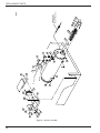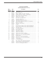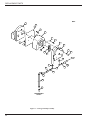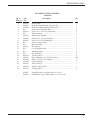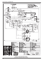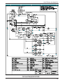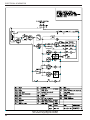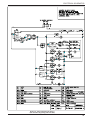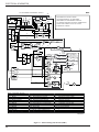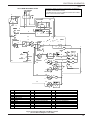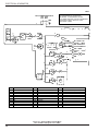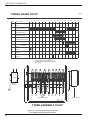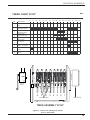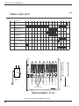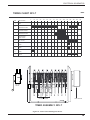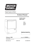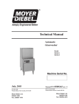
1
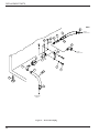
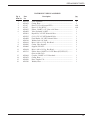
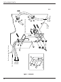
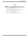
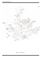
Simply Engineered Better
Technical Manual
Undercounter
Dishwasher
Model
501-HT
501-HTN
501-LT
Machine Serial No.
July, 2003
P.O. Box 4183
Winston-Salem, North Carolina 27115-4183
Moyer Diebel, U.S.
336/661-1992
Fax: 336/661-1979
Manual P/N
0508576 REV. J
2674 N. Service Road
Jordan Station, Ontario, Canada L0R 1S0
Moyer Diebel, Ltd.
905/562-4195
Fax: 905/562-4618
Complete the information below so it will be available for quick reference.
Model Number __________________________
Serial Number ________________________
Voltage and Phase ______________________________________________________________
Moyer Diebel Parts Distributor _______________________________
(if applicable)
Phone _____________
_____________________________________________________________________________
Moyer Diebel Service Agency ________________________________
Phone _____________
_____________________________________________________________________________
Moyer Diebel Service:
Moyer Diebel Limited
Moyer Diebel, US
Phone:
Phone:
1-905-562-4195
1-800-263-5798
Fax:
1-905-562-4618
1-336-661-1992
1-800-228-8350
Fax:
1-336-661-1660
NOTE: When calling to order parts, be sure to have the model number, serial number, voltage,
and phase of your machine, along with your customer account number.
COPYRIGHT © 2003 by Moyer Diebel
REVISIONS
Revision History
Revision
Date
Revised
Pages
Serial Number
Effectivity
Comments
12/16/92
All
—
8/29/93
18-19
3100
8/29/93
20-21
—
8/29/93
24-25
3210
8/29/93
27
—
Added part numbers for valve kit.
8/29/93
30-31
—
Changed booster element part numbers.
8/29/93
40-42
—
Revised wiring schematics.
6/30/95
28-29
5733
Redesign of inlet chute.
6/30/95
30-31
5713
Redesign of booster assembly.
6/30/95
43-46
—
9/28/95
20-21
6264
Redesign drain, eliminated tank overflow.
4/18/96
—
6795
Models 501UT, UTLC, UTL discontinued.
6/6/96
18, 38
6984
Redesign door safety switch, added magnetic
reed switch and relay.
6/6/96
42-45
6984
Revised wiring schematics.
8/1/96
—
7220
Redesigned all models to have same height.
9/1/96
26-27
7306
Flexible fill hose added.
1/9/97
42
6984
Revised wiring schematic.
5/16/98
21
9624
Redesigned drain hose
(P/N 0507265 changed to 0509302).
9/9/98
42-44
6984
Revised wiring schematics.
2/28/00
13
—
Revised troubleshooting instructions item #1, All
switches on except extended wash switch.
11/16/00
39
—
Replaced P/N 112204 thermostats with P/N 109069 in
booster for all serial numbers.
8/22/01
21
—
Revised part numbers on hose clamps and hose.
2/5/03
39
––
Replaced 108391 with 113622 thermometer.
4/23/03
3,8,14,38,40,42,50
W7604
4/23/03
29,31
––
Changed hose P/N 0509214 to P/N 107417.
7/23/03
27, 29
––
Changed hose P/N 0502665, 0509214, 107214 to 107417
Reissue of manual and new replacement parts lists.
Redesign of door catch plunger and housing.
Redesign of thermometer fitting.
Redesign of upper wash arm hub and gasket.
Added timer charts and diagrams.
Added Final Rinse Sentry information.
THIS PAGE
INTENTIONALLY
LEFT BLANK
CONTENTS
CONTENTS
Page
INTRODUCTION.......................................................................................................................................
1
WARRANTY ..............................................................................................................................................
2
GENERAL ..................................................................................................................................................
3
INSTALLATION ........................................................................................................................................
5
Unpacking ............................................................................................................................................
5
Electrical Connections..........................................................................................................................
5
Plumbing Connections .........................................................................................................................
6
Detergent ..............................................................................................................................................
6
Rinse-Aid .............................................................................................................................................
6
Chemical Sanitizer ...............................................................................................................................
6
Completing Installation ........................................................................................................................
7
OPERATION ..............................................................................................................................................
8
Operation Summary .............................................................................................................................
8
Operation Procedures ...........................................................................................................................
8
Extended Wash Cycle ..........................................................................................................................
9
MAINTENANCE........................................................................................................................................ 10
Cleaning Schedule................................................................................................................................ 10
Deliming............................................................................................................................................... 11
Deliming Process.................................................................................................................................. 11
Maintenance Schedule.......................................................................................................................... 12
TROUBLESHOOTING .............................................................................................................................. 13
REPLACEMENT PARTS........................................................................................................................... 15
ELECTRICAL DIAGRAMS ...................................................................................................................... 42
TIMER CHARTS and DIAGRAMS........................................................................................................... 50
LIST OF FIGURES
Figure 1—Track and Panel Assembly......................................................................................................... 16
Figure 2—Door and Switch Assembly........................................................................................................ 18
Figure 3—Tank Heat and Drain .................................................................................................................. 20
Figure 4—Pump Assembly ......................................................................................................................... 22
Figure 5—Wash System Assembly............................................................................................................. 24
Figure 6—Water Inlet Piping ...................................................................................................................... 26
Figure 7—Fill System ................................................................................................................................. 28
Figure 8—Booster Assembly ...................................................................................................................... 30
CONTENTS
Figure 9—Detergent Pump Assembly....................................................................................................... 32
Figure 10—Sanitizer/Rinse-Aid Pump Assembly....................................................................................... 34
Figure 11—Drain Pump Assembly ............................................................................................................. 36
Figure 12—Control Cabinet ........................................................................................................................ 38
Figure 13—Electrical Diagram, 501-HT (For machines beginning with S/N W7604) .............................. 42
Figure 14—Electrical Diagram, 501-HT (For machines ranging from S/N 6984 to W7604) .................... 43
Figure 15—Electrical Diagram, 501-HTN (For machines beginning with S/N 6984) ............................... 44
Figure 16—Electrical Diagram, 501-LT (For machines beginning with S/N 6984) .................................. 45
Figure 17—Electrical Diagram, 501-HT (50Hz) ........................................................................................ 46
Figure 18—Electrical Diagram, 501-HT/UT/UTLC (For machines built prior to S/N 6984) .................... 47
Figure 19—Electrical Diagram, 501-HTN (For machines built prior to S/N 6984) ................................... 48
Figure 20—Electrical Diagram, 501-LT/UTL (For machines built prior to S/N 6984) ............................. 49
Figure 21—Timer Chart and Diagram, 501-HT (For machines beginning with S/N W7604) ................... 50
Figure 22—Timer Chart and Diagram, 501-HT (For machines prior to S/N W7603) ............................... 51
Figure 23—Timer Chart and Diagram, 501-UT.......................................................................................... 52
Figure 24—Timer Chart and Diagram, 501-LT .......................................................................................... 53
INTRODUCTION
INTRODUCTION
Welcome to Moyer Diebel.
Thank you for choosing Moyer Diebel and for allowing us to take care of your dishwashing needs.
This manual covers several models. Model numbers are shown on the front cover.
Your machine has been completely assembled, inspected, and thoroughly tested at our factory to
eliminate problems at installation before it was shipped to your installation site. This manual
provides:
• Warranty information
• Installation and operation procedures
• Maintenance instructions
• Troubleshooting guide
• Replacement parts lists.
Complete and return your warranty registration card as soon as possible.
Moyer Diebel constantly improves its products; therefore, specifications contained in this
manual may have changed.
For your protection, factory authorized parts should always be used.
Replacement parts may be ordered directly from Moyer Diebel or from your Moyer Diebel
authorized parts distributor or service agency.* When ordering parts, supply the model number,
serial number, voltage and phase of your machine, the part number, part description, and quantity.
*Moyer Diebel can only ship parts to customers with accounts or by C.O.D.
1
WARRANTY
LIMITED WARRANTY
Moyer Diebel, P.O. Box 4183, Winston-Salem, North Carolina 27115, and P. O. Box 301, 2674 North Service Road,
Jordan Station, Ontario, Canada L0R 1S0 warrants machines, and parts, as set out below.
Warranty of Machines: Moyer Diebel warrants all new machines of its manufacture bearing the name “Moyer Diebel”
and installed within the United States and Canada to be free from defects in material and workmanship for a
period of one (1) year after the date of installation or fifteen (15) months after the date of shipment by Moyer
Diebel, whichever occurs first. [See below for special provisions relating to Model Series DF and SW.] The
warranty registration card must be returned to Moyer Diebel within ten (10) days after installation. If warranty
card is not returned to Moyer Diebel within such period, the warranty will expire after one year from the date
of shipment.
Moyer Diebel will not assume any responsibility for extra costs for installation in any area where there are
jurisdictional problems with local trades or unions.
If a defect in workmanship or material is found to exist within the warranty period, Moyer Diebel, at its
election, will either repair or replace the defective machine or accept return of the machine for full credit;
provided, however, as to Model Series DF and SW, Moyer Diebel’s obligation with respect to labor associated
with any repairs shall end (a) 120 days after shipment, or (b) 90 days after installation, whichever occurs first.
In the event that Moyer Diebel elects to repair, the labor and work to be performed in connection with the
warranty shall be done during regular working hours by a Moyer Diebel authorized service technician.
Defective parts become the property of Moyer Diebel. Use of replacement parts not authorized by Moyer
Diebel will relieve Moyer Diebel of all further liability in connection with its warranty. In no event will
Moyer Diebel’s warranty obligation exceed Moyer Diebel’s charge for the machine. The following are not
covered by Moyer Diebel’s warranty:
a. Lighting of gas pilots or burners.
b. Cleaning of gas lines.
c. Replacement of fuses or resetting of overload breakers.
d. Adjustment of thermostats.
e. Adjustment of clutches.
f. Opening or closing of utility supply valves or switching of electrical supply current.
g. Adjustments to chemical dispensing equipment.
h. Cleaning of valves, strainers, screens, nozzles, or spray pipes.
i. Performance of regular maintenance and cleaning as outlined in operator’s guide.
j. Damages resulting from water conditions, accidents, alterations, improper use, abuse, tampering, improper
installation, or failure to follow maintenance and operation procedures.
Examples of the defects not covered by warranty include, but are not limited to: (1) Damage to the exterior or
interior finish as a result of the above, (2) Use with utility service other than that designated on the rating plate,
(3) Improper connection to utility service, (4) Inadequate or excessive water pressure, (5) Corrosion from chemicals
dispensed in excess of recommended concentrations, (6) Failure of electrical components due to connection of
chemical dispensing equipment installed by others, (7) Leaks or damage resulting from such leaks caused by
the installer, including those at machine table connections or by connection of chemical dispensing equipment
installed by others, (8) Failure to comply with local building codes, (9) Damage caused by labor dispute.
Warranty of Parts: Moyer Diebel warrants all new machine parts produced or authorized by Moyer Diebel to be free
from defects in material and workmanship for a period of 90 days from date of invoice. If any defect in
material and workmanship is found to exist within the warranty period Moyer Diebel will replace the
defective part without charge.
DISCLAIMER OF WARRANTIES AND LIMITATIONS OF LIABILITY. MOYER DIEBEL’S WARRANTY IS
ONLY TO THE EXTENT REFLECTED ABOVE. CHAMPION MAKES NO OTHER WARRANTIES, EXPRESS
OR IMPLIED, INCLUDING, BUT NOT LIMITED, TO ANY WARRANTY OF MERCHANTABILITY, OR
FITNESS OF PURPOSE. MOYER DIEBEL SHALL NOT BE LIABLE FOR INCIDENTAL OR CONSEQUENTIAL
DAMAGES. THE REMEDIES SET OUT ABOVE ARE THE EXCLUSIVE REMEDIES FOR ANY DEFECTS
FOUND TO EXIST IN MOYER DIEBEL DISHWASHING MACHINES AND MOYER DIEBEL PARTS, AND
ALL OTHER REMEDIES ARE EXCLUDED, INCLUDING ANY LIABILITY FOR INCIDENTALS OR
CONSEQUENTIAL DAMAGES.
Moyer Diebel does not authorize any other person, including persons who deal in Moyer Diebel dishwashing machines
to change this warranty or create any other obligation in connection with Moyer Diebel Dishwashing Machines.
2
GENERAL
GENERAL
This manual covers the Moyer Diebel undercounter dishwashing machine. This machine is fully
automatic and is equipped with a 1/2 H.P. pump motor. All models are available for mounting
directly to the floor or on optional stands (see accessories listed on page 4).
Standard equipment includes:
-Automatic tank fill
-Upper and lower wash/rinse arms
-Common utility connections
-Two dish racks (peg and flat)
-120 Volt control circuit
-Exclusive vent design for
-Convenient, easy to use controls
venting of condensation
-Door latch activated start switch
-Stainless steel heavy-gauge construction,
-Detergent pump
including base
-Final Rinse Sentry (high temp models only)
This series of dishwashers is available in the following models:
Model Numbers
501HT, 501HTN, 501LT
•
The 501HT model is a high temperature (82oC/180oF rinse) sanitizing model with booster.
•
The 501HTN model is a high temperature (82oC/180oF rinse) sanitizing model without
booster.
•
The 501LT model is a low temperature (60oC/140oF rinse) sanitizing model for use with
5.25% or 8.4% sodium hypochlorite solution (chlorine bleach) as a sanitizing agent. The
rinse aid pump is optional.
Options
• Kit 504 - Top and side panels (P/N 0708756)
• Kit 505 - Top panel only (P/N 0708744)
• Kit 506 - Left side panel only (P/N 0708745)
• Kit 507 - Right side panel only (P/N 0708746)
• Kit 508 - Rinse aid pump kit (P/N 0708754)
• Kit 510 - Extended reach pumped drain kit (HT, HTN, LT) (P/N 0708766)
• Kit 511 - 30oC/70oF temperature rise booster (for 49oC/11OoF supply water).
3
GENERAL
Accessories
• 17RS - 17" rack stand (raises working height and adds rack storage)
• 17T - 17" cabinet (raises working height and adds storage)
• CST - Combination sink/table (scraping and sorting station)
• 0501653 - Dish Rack (Peg Rack)
• 0501654 - Silverware Rack (Flat Bottom Rack)
• 0710364 - 5" Base/Stand
Electrical Power Requirements
Model
Voltage
115/60/1
115/60/1
208/60/1
240/60/1
208/60/1
240/60/1
501LT
501HTN
501HT
501HT
501HT
501HT
Booster
Rise
N/A
N/A
40
40
70
70
Machine
Full Load Amp
12
12
36
40
48
55
Power Requirement
(125% Service Factor)
15
15
44
49
59
68
NOTE:
208-240V/60Hz/1PH electrical supply service must be a 3-wire plus ground for connection
as shown.
00023
115v
—3-Wire Plus Ground Diagram
115v
L1
4
L2
N
G
INSTALLATION
INSTALLATION
Unpacking
!
WARNING:
Care should be taken when lifting the machine to prevent damage.
1.
Immediately after unpacking your machine, inspect for any shipping damage. If damage is
found, save the packing material and contact the carrier immediately.
2.
Remove the dishwasher from the skid. Adjust the feet if required, then move the machine to
its permanent location.
3.
Level the machine (if required) by placing a level on the top of the machine and adjusting
the feet. Level the machine front-to-back and side-to-side.
!
CAUTION:
After locating your machine, it must meet local health codes. An example may be to seal
your machine to the floor using a good grade of silicone sealant.
Electrical Connections
!
WARNING:
Electrical and grounding connections must comply with the National Electrical Code
and/or Local Electrical Codes.
!
WARNING:
When working on the dishwasher, disconnect the electric service and tag it to indicate work
is being done on that circuit.
1.
The electrician should compare the electrical specifications on the machine electrical
junction box (located behind the front panel) to the electrical power supply before
connecting the machine to the incoming service at a fused disconnect switch.
NOTE:
The 208-240V/60Hz/1PH electrical supply service for this machine must be a
3-wire plus ground service.
2.
On the 208V-240V models, a knock-out is provided at the rear of the junction box (located
behind the front panel) for electrical service connections. A fused disconnect switch or
circuit breaker (supplied by user) is required to protect each power supply circuit.
3.
On 115V models, your machine is already equipped with a 4-foot power cord and plug
suitable for 115V-15A service.
5
INSTALLATION
Plumbing Connections
!
CAUTION:
Plumbing connections must comply with local sanitary and plumbing codes.
Water Connections
1.
Connect the hot water supply (60oC/ 140oF Min) to the 1/2" I.D. fill hose. The fill solenoid
valve is equipped with a flow control that will accept water pressures from 172 kPa/25 psi
to 665 kPa/95 psi.
2.
Install a manual shut-off valve in the water supply line to accommodate servicing the
machine. The shut-off valve should be the same size or larger than the supply line.
3.
The fill solenoid valve is equipped with a built-in strainer to protect from particles in the
water supply.
Drain Connections
1.
All Models are supplied with a flexible 5/8" I.D. drain hose, which must be connected to a
1-1/2" drain using a wye (Y) fitting.
Detergent
1.
Use a qualified detergent/chemical supplier for your detergent, rinse aid, and chemical
sanitizer needs.
2.
Your machine is supplied with a detergent dispensing pump that is internally wired and
ready for use. Using a liquid detergent, insert the labeled Detergent pickup tube into the
detergent container. The pickup tube has a strainer on the end to prevent crystallized
chemical from clogging the supply lines.
3.
The cycle timer located in the main control cabinet is equipped with adjustable cams for the
chemical dispensing pump(s). The cams control the length of time that the pumps operate.
A qualified person may adjust the cam settings if necessary. Refer to the timer chart
diagram(s) at the end of the manual for timer cam locations and factory time settings.
NOTE:
A nonclorinated detergent is recommended for your dishwasher.
Rinse Aid
1.
An optional rinse aid pump may be supplied for all models. Using a liquid rinse aid, insert
the labeled Rinse Aid pickup tube into the rinse aid container.
Chemical Sanitizer
6
1.
Model 501LT is supplied with an internally wired chemical sanitizer dispensing pump.
Using a 5.25% or 8.4% sodium hypochlorite solution, insert the labeled Chemical Sanitizer
pickup tube into the chemical sanitizer container.
2.
Contact your chemical supplier for adjustment of the chemical sanitizer.
INSTALLATION
Completing Installation
1.
Remove any foreign material from inside the machine.
2.
Center the scrap screen over the sump opening.
3.
Prime the booster using the following procedure (if applicable).
!
CAUTION:
To prime the booster, the following procedure must be followed AFTER the electrical
and plumbing connections have been made.
a.
Close the front door.
b.
Remove the front panel.
c.
Locate the Installation and Service toggle switch on the extreme left side of
the control box.
d.
Press the toggle switch down to the Booster Fill position and hold it
approximately 1 minute (or until water can be heard entering the machine).
e.
Release the toggle switch to stop the water flow.
f.
You have completed the booster priming process.
NOTE:
Push the Installation and Service toggle switch to the UP position.
Electrical power is now supplied to the machine.
!
WARNING:
Failure to prime the booster may cause damage to the booster elements and other
electrical components and will void the warranty.
4.
After plumbing and electrical connections are completed, check the machine for water leaks
by depressing the ON/FILL switch on the front panel, then close and latch the door. This
allows the tank to fill and to complete the rinse cycle. Check for leaks.
5.
Open the door and check the water level. The water level should barely cover the scrap
screen.
6.
Depress the OFF/DRAIN switch and close and latch the door to drain the tank. This allows
the machine to complete the 100-second wash and drain cycle. Check the drain plumbing
for leaks.
7.
Replace the front panel. Installation is now complete.
7
OPERATION
OPERATION
Operation Summary
The following is a summary of your Undercounter Dishwashing Machine operating cycle:
1.
The cycle begins when you depress the front edge of the door latch toward the door.
2.
The green cycle lamp lights and the pump starts.
3.
The pump runs during the wash cycle for approximately 80 seconds. The wash cycle
duration is extended if booster is not up to temperature.
4.
The pump stops, and the drain is opened.
5.
After a 2-3 second pause, the pump drain cycle begins and continues for approximately
30 seconds.
6.
After a 2-3 second pause, the fill valve opens, and the pump starts for the rinse cycle.
7.
Within approximately 25 seconds, the rinse cycle is complete. The pump stops, the green
cycle lamp turns off, and the cycle is complete.
8.
Open the door and remove the rack of clean ware. The door must remain open for 5 seconds
to allow the timer to reset before starting another cycle.
Operation Procedures
The operation of your dishwasher will be more efficient when these procedures are followed:
1.
Check that the spray arms and scrap screen are in place.
2.
Close the door and depress the front edge of the door latch toward the door. Push the
ON/FILL switch to the ON position. The tank will begin filling with water. This procedure
is followed only when the tank is empty.
3.
When the tank is full, check the wash tank temperature gauge. Minimum wash temperatures are:
• 501HT, 501HTN - 66°C/150°F.
• 501LT - 60°C/140°F.
8
4.
Scrap and preflush all items to be washed, and load the items into the rack. DO NOT
OVERLOAD the rack. Wash only one layer of silverware in a rack.
5.
Open the door and insert the rack into the machine.
6.
Shut the door, and depress the door latch. This will start the wash cycle. The green cycle
lamp located on the front control panel will light. This lamp will remain on until the entire
wash and rinse cycle is completed.
OPERATION
NOTE:
The machine may be stopped at any time by opening the door. When restarted, the cycle
does not start over. It will continue from the point at which it was interrupted.
7. Check the rinse temperature during the final rinse (120 seconds into cycle). The rinse
temperature must be 82°C/180°F minimum for models 501HT, 501HTN, 501UT and
501UTLC and 60°C/140°F for models 501LT and 501UTL.
8. The pump will automatically stop and the green cycle light will turn off indicating the cycle
is completed.
9. Open the door and remove the rack.
10. Repeat steps 4-9 for additional cycles. Machine operation is automatic.
11. CLEAN the scrap screen after every meal period. During heavy usage, the scrap screen
should be cleaned more frequently.
!
CAUTION:
Poor machine performance and/or damage to the machine can occur if the scrap
screen becomes clogged with soil or waste particles.
12. After completing usage for the day, water in the tank should be drained by depressing the
OFF/DRAIN switch and closing and latching the door. This initiates a 100 second wash and
drain cycle that drains the tank.
!
CAUTION:
DO NOT LEAVE WATER IN THE TANK OVERNIGHT. Water left in the tank
overnight will allow harmful chemicals to deteriorate the tank.
Extended Wash Cycle
On models 501HT, 501HTN, 501UT and 501UTLC, but not on models 501LT and 501UTL, an
extended wash cycle is available for pots, pans and heavily soiled items.
To use the Extended Wash Cycle:
1. Insert the loaded rack into the machine. Close the door and depress the latch. Wait 10
seconds for the detergent to be dispensed automatically.
2. Flip the Extended Wash/Delime Switch to the UP position. The green cycle light will go
out, indicating that the machine is in a CONTINUOUS wash mode.
3. When your desired wash time has passed, flip the Extended Wash/Delime Switch to the
DOWN position. The green cycle light will come on, indicating a return to the normal wash
mode. The machine will now complete the remaining portion of the automatic cycle.
9
MAINTENANCE
MAINTENANCE
The efficiency and life of your machine is increased by regularly scheduled preventive
maintenance. A well maintained machine gives better results and service. An investment of a few
minutes of daily maintenance will be worthwhile.
The best maintenance you can provide is to keep your machine clean. Components that are not
regularly cleaned and flushed will clog and become inoperative.
Intervals shown in the following schedules represent an average length of time between necessary
maintenance. Maintenance intervals should be shortened whenever your machine is faced with
abnormal working conditions, hard water, or multiple shift operations.
Cleaning Schedule
•
Daily-Every 8 Hours
1. Depress the OFF/DRAIN switch to OFF and close and latch the door to drain the tank.
2. Open the door and remove both the upper and lower spray arms by unscrewing the
knurled fastener holding each spray arm.
3. Remove the scrap screen carefully to keep soil or waste particles from falling into the
sump.
4. Clean inside the tank with clean water. Backflush the scrap screen until it is clean. Do
not strike the screen against solid objects.
5. Clean the wash arms to remove any debris from spray openings. Do not strike the spray
arms against solid objects.
6. Reinstall the scrap screen and spray arms.
7. Leave the door open overnight to allow drying.
8. Report any unusual conditions to your supervisor.
•
Meal Periods
1. Clean the scrap screen after every meal period and more frequently during heavy usage.
Do not allow the scrap screen to become clogged with soil or waste particles.
10
MAINTENANCE
Deliming
Your dishwasher should be delimed regularly as required. This will depend on the mineral
content of your water.
Inspect your machine interior for lime deposits. If deliming is required, a deliming agent should
be used for best results.
If you have the chemical sanitizing model (501LT or 501UTL), carefully follow the following
procedure before deliming:
!
DANGER:
Deliming solution or other acids must not come in contact with household bleach (sodium
hypochlorite) or any chemicals containing chlorine, iodine, bromine, or fluorine. Mixing
will cause hazardous gases to form. Skin contact with deliming solutions can cause severe
irritation and possible chemical burns. Consult your chemical supplier for specific safety
precautions.
1.
Remove the sanitizer tube from the container. Place the tube into a container of hot water.
2.
Depress and hold the SANITIZER prime switch (located on the front panel) until clear
water enters the tank through the fill air gap.
3.
Close the door and depress the door latch. Complete two operating cycles to purge the
machine of all sanitizer.
Deliming Process
Complete the following procedure to delime your machine:
1.
Add the delime chemical to wash the tank (per chemical supplier specifications).
2.
Close and latch the door.
3.
On models 501HT, 501HTN, 501UT and 501UTLC depress the EXTENDED
WASH/DELIME switch on the front panel as soon as the cycle starts. On models 501LT
and 501UTL, proceed to step 5 of this procedure.
NOTE:
The EXTENDED wash/delime switch will operate only during the wash cycle.
When this switch is in the ON position, the machine stays in the wash cycle until the
switch is OFF. After switching to OFF, the machine will finish the cycle.
4.
After 2-1/2 to 3 minutes (or as long as required), turn off the EXTENDED WASH/
DELIME switch. The machine will finish a complete cycle.
5.
Complete two cycles with the machine empty to purge the machine of all delime chemicals.
6.
Deliming is complete.
11
MAINTENANCE
Maintenance Schedule
•
•
12
As Required
1.
Check the temperature gauge reading.
2.
Check the chemical supplies and refill as necessary.
Weekly
1.
Inspect all water lines for leaks and tighten them at joints if required.
2.
Clean all detergent residue from the exterior of the machine.
3.
Check the drain for leaks.
4.
Clean accumulated scale from the heating element.
5.
Remove and closely inspect each spray arm for blockage.
6.
Check for damage to the scrap screen. Ineffective screening can cause wash system
failures.
7.
Clean the detergent, sanitizer, and rinse aid supply tubes. Complete the following
procedure:
a.
Remove the detergent, sanitizer, and rinse aid pick-up tube(s) from the
container(s). Place the tube(s) into a container of hot water.
b.
Depress and hold the DET prime switch (located on the front panel) until clear
water enters the tank through the fill air gap (located on the right side of the
tank).
c.
If your machine is equipped with a sanitizer and/or rinse aid pump, follow the
same procedure by pressing the SANITIZER and/or the RINSE AID prime
switch until clear water enters the tank through the fill air gap.
d.
When completed, remove the pickup tubes from the hot water and reinsert them
into the correct chemical containers. Repeat the priming procedures to ensure
that chemicals have filled the tubes for the next operating period.
e.
Run a complete cycle to flush chemicals from the tank.
TROUBLESHOOTING
TROUBLESHOOTING
Before determining any specific cause of a breakdown or abnormal operation of your dishwasher,
check that:
1.
Turn all switches ON, except for the extended wash switch.
2.
Wash arms are clean.
3.
Scrap screen is properly positioned and clean.
4.
Thermostat(s) are at their correct setting.
5.
Sanitizer, detergent, and rinse additive dispensers are adequately filled.
6.
All plumbing valves are open.
If a problem still exists, use the following table for troubleshooting.
CONDITION
CAUSE
SOLUTION
Machine will not start
Door not closed and latched ................
Main switch off, or unit unplugged ....
Make sure door is fully latched
Check disconnect or plug into outlet
Make sure the extended wash switch is in
the OFF position.
Low or no water
Main water supply is turned off .........
Turn on house water supply
Chemical not feeding
No chemical in container.....................
Feed tubes to/from chemical ...............
pump clogged
Screen on feed tube clogged................
Tubing kinked or split .........................
Replace or fill container
Clear obstruction and flush
with hot water
Clean and replace
Straighten or replace tubing
Water temperature
is low when in use
Incoming water temperature................
at machine too low
Hi limit tripped
Raise temperature to
60°C/140°F for all machines
Reset hi limit
Insufficient pumped spray
pressure
Clogged spray arm ..............................
Scrap screen full ..................................
Clean
Must be kept clean and in place
Low final rinse temperature
Low incoming water............................
temperature
Check the booster - be sure the
thermostat is set to maintain 66°C/180°F
temperature (501LT is 60°C/140°F)
(Check all valves to be
sure they are clean and operating)
Reset hi limit
Hi limit tripped
Poor washing results
Water level low in wash tank ..............
should be at or 1/2" (13mm)
above screen
Detergent dispenser not.......................
operating properly
Insufficient detergents .........................
Detergent setting too low ...................
Wash water temperature too low.........
Wash arm clogged ..............................
Improperly scraped dishes...................
Ware being improperly........................
placed in rack
Improperly cleaned .............................
equipment
Electric element has ............................
soil/lime buildup
Check fill valve and water pressure
Contact service agent
Check and fill
Contact detergent supplier
Contact detergent supplier
See above booster temperatures
Clean wash arm
Check scraping procedures
Use proper racks - do not overload
racks
Unclog wash arms to maintain
proper pressure and flow conditions
Clean and delime
13
TROUBLESHOOTING
TROUBLESHOOTING (con’t)
CONDITION
14
CAUSE
SOLUTION
No water in wash well
Opening door prior ..............................
to cycle completion
Close door. Wait for green cycle light
to go out before opening door.
No water in wash tank
after activating the
ON/FILL switch
Door not latched ..................................
Latch door.
Wait for wash tank to fill.
Cycle time increases
with each cycle
Incoming water....................................
temperature is too low
Raise temperature to 60°C/140°F
for all machines.
REPLACEMENT PARTS
REPLACEMENT
PARTS
15
REPLACEMENT PARTS
00001
14
13
12
14
9
8
11
6
7
4
3
5
14
2
10
1
Figure 1 — Track and Panel Assembly
16
REPLACEMENT PARTS
TRACK/PANEL ASSEMBLY
Fig. 1
Item No.
1
2
2
3
4
5
6
7
8
9
10
11
12
13
14
Part
No.
0508751
0308615
0308646
0308646
0308748
0501413
0501415
0308632
0308631
0708647
0308736
0308734
0308737
0308735
0501412
Description
Screw, 10-32 x 1-1/2" Lg. Truss Head .......................................
Front Panel (HT, HTN, LT) (Prior to S/N 6795) ........................
Front Panel (HT, HTN, LT) (S/N 6795 and above)....................
Front Panel (UTL, UT, UT-LC) .................................................
Front Panel (UT-MC) .................................................................
Screw, 10-32 x 3/8" Lg. Round Head.........................................
Screw, 10-32 x 5/8" Lg. Round Head.........................................
Track, RH ...................................................................................
Track, LH ...................................................................................
Cover, Vent .................................................................................
Panel, LH Side (UT, UTL, UT-LC, HT, HTN, LT) ....................
Panel, Rear (UTL, UT-LC, HT, HTN, LT).................................
Panel, RH Side (UT, UTL, UT-LC, HT, HTN, LT)....................
Panel, Top (UT, UTL, UT-LC, HT, HTN, LT) ...........................
Screw, 10-32 x 3/8" Lg. Truss Head (UT, UTL, UT-LC)...........
Qty
2
1
1
1
1
2
4
1
1
2
1
1
1
1
10
17
REPLACEMENT PARTS
00020
11
1
4
5
7
8
6
10
12
9
3
1
13
14
2
1
18
15
16
17
Figure 2 — Door Switch Assembly
18
15
REPLACEMENT PARTS
DOOR & SWITCH ASSEMBLY
(For Machines Beginning with S/N 6984 and Above)
Fig. 2
Item No.
1
2
3
4
5
6
7
8
9
10
11
12
13
14
15
16
17
18
-
Part
No.
0501412
0308596
0308597
0508721
0709462
0509436
0508545
104883
0709431
111090
0508544
0508543
0501539
0503715
0501421
0708564
0501501
0708527
0508555
Description
Screw, 10-32 x 3/8" Truss Head .................................................
Plate, Door Latch........................................................................
Handle, Door Latch ....................................................................
Retaining Ring, Plunger .............................................................
Assembly, Door Catch (Includes items 4, 6) ..............................
Plunger, Door Catch ...................................................................
Gasket, Steam .............................................................................
Screw, Round Head (6-32 x 3/8")...............................................
Plate, Door Switch......................................................................
Switch, Door Magnetic Reed .....................................................
Gasket, Upper Door....................................................................
Gasket, Side Door.......................................................................
Nut, Plain 1/4-20 ........................................................................
Spring, Door Hinge ....................................................................
Bolt, 1/4-20 x 1-1/4" Hex Head..................................................
Arm, Door Hinge........................................................................
Washer, Lock 1/4" Split .............................................................
Door............................................................................................
Wiring, Harness, Door Switch....................................................
0708526
Door Assy. (includes items 1-6, 18)
Qty
6
1
1
1
1
1
2
2
1
1
1
2
2
2
4
2
2
1
1
For machines built prior to S/N 6984 order Door Switch Conversion Kit, P/N 0709427.
19
REPLACEMENT PARTS
00004
1
3
2
3
4
TO RINSE
18
17
16
19
14
15
14
13
11
16
11
10
12
THERMOSTAT
(CALLED OUT IN
CONTROL BOX)
5
THERMOMETER
(CALLED OUT IN
CONTROL BOX)
6
7
21
TO DRAIN
19
19
8
20
9
Figure 3 — Tank Heat and Drain
20
TO PUMP
DRAIN
REPLACEMENT PARTS
TANK HEAT/DRAIN ASSEMBLY
Fig. 3
Item No.
1
2
3
4
5
6
7
8
9
10
11
12
13
14
15
16
17
18
19
20
21
Part
No.
0508628
0508536
0508537
0508578
0501539
0501501
0308611
0306618
0501418
0508873
0501836
0508872
108954
110562
201029
0308655
0508579
104414
0510082
0507265
0509302
Description
Scrap Screen...............................................................................
Heater Element 220V-60Hz-1PH (HT, UT, UT-LC)..................
Heater Element 110V-60Hz-1PH (HTN, LT, UTL) ...................
Adapter, Pump Tube...................................................................
Nut, Plain 1/4-20 ........................................................................
Washer, Lock, 1/4" Split.............................................................
Support, Drain Valve ..................................................................
Valve, Drain................................................................................
Screw, 1/4-20 x 1/2" Lg. Round Head .......................................
Adapter, Thermostat ...................................................................
O-Ring, Thermostat....................................................................
Adapter, Thermometer ...............................................................
Nut, Grip 6-32 w/Nylon Insert ...................................................
Thermostat, High-Limit .............................................................
Locknut, 1/2 NPT Nickel-Plated ................................................
Tube, Pump Outlet .....................................................................
Nut, Jam 1"-8 .............................................................................
O-Ring........................................................................................
Clamp, Hose ...............................................................................
Hose, 5/8" ID x 7/8" OD PVC Braided......................................
Hose, 5/8" ID x 1" OD PVC Braided.........................................
Qty
1
1
1
1
2
2
1
1
2
1
2
1
2
1
2
1
1
1
2
A/R
6 Ft.
21
REPLACEMENT PARTS
00005
1
3
2
4
5
6
7
8
9
10
11
13
14
12
TANK
BOTTOM
Figure 4 — Pump Assembly
22
REPLACEMENT PARTS
PUMP ASSEMBLY
Fig. 4
Item No.
1
2
3
4
5
6
7
8
9
10
11
12
13
14
-
Part
No.
0508542
0501431
0501425
0508793
0502741
0502704
0502746
0502745
0502703
0502744
0502743
0501881
0508665
0508570
0710071
107966
Description
Spindle, Lower Wash Arm .........................................................
Screw, 8-32 x 1-1/8" Round Head..............................................
Screw, 8-32 x 5/8" Round Head .................................................
Housing, Diffuser .......................................................................
Diffuser.......................................................................................
Impeller ......................................................................................
Adapter Plate, Suction................................................................
Plate, Drain lnlet.........................................................................
O-ring .........................................................................................
Propeller/Rotating Seal Assembly .............................................
Mounting Plate/Seal Assembly (Includes Item 10)....................
Gasket, Pump .............................................................................
Screw, 10-32 x 5/8" Hex Washer Head ......................................
Washer, Sealing Teflon...............................................................
Pump/Motor Assembly (lncludes items 1-11)* .........................
Nut, Grip 10-32, SST (Not Shown) (For mounting Item 1).......
Qty
1
4
4
1
1
1
1
1
1
1
1
1
8
8
1
1
* Motor not available as a separate repair part
23
REPLACEMENT PARTS
00006
2
1
3
4
TOP OF
HOOD
5
6
7
8
9
10
10
11
12
13
14
PUMP
TANK BOTTOM
2
FROM
PUMP
Figure 5 — Wash System Assembly
24
REPLACEMENT PARTS
WASH SYSTEM ASSEMBLY
Fig. 5
Item No.
1
2
3
4
5
6
7
8
9
10
11
12
13
14
-
Part
No.
0508549
0502563
0708650
0503588
0501412
0508541
0705047
0505042
0308783
0501563
0308158
0501684
0705049
0508540
0708874
Description
Hose, Upper Wash ......................................................................
Clamp, Hose 1"...........................................................................
Spindle, Upper Wash Arm..........................................................
O-ring, 1-1/8" x 1-3/8" ...............................................................
Screw, 10-32 x 3/8" Lg. Truss Head...........................................
Bushing, Upper Wash Arm.........................................................
Wash Arm, Upper .......................................................................
Pivot, Upper Wash Arm..............................................................
Retainer, Upper Pivot S/A ..........................................................
Screw, #8 x 3/8" (Sheet Metal) Truss Head................................
Nut Clip, Spray Arm...................................................................
Nut, Spray Arm Lock .................................................................
Wash Arm, Lower.......................................................................
Bushing, Lower Wash Arm ........................................................
Lower Wash Arm Assembly (includes items 10-14)
Qty
1
2
1
1
3
1
1
1
1
4
1
1
1
1
25
REPLACEMENT PARTS
00021
16
WATER
CONNECTION
2
16
11 13
10
15
7
12
9
WATER
CONNECTION
6
5
7
8
2
4
3
1
2
TO BOOSTER
OR FILL
Figure 6 — Water Inlet Piping
26
REPLACEMENT PARTS
WATER INLET PIPING ASSEMBLY
Fig. 6
Item No.
1
2
3
4
5
6
7
8
9
10
11
12
13
14
15
16
Part
No.
0503718
0503679
107417
107417
0502653
0504952
0502811
0505235
0504958
0501501
0501419
0300203
0300065
0501424
0503713
0502618
0503679
0509526
0505320
Description
Foot, Adjustable .........................................................................
Clamp, Hose ...............................................................................
Hose l/2" I.D. (all except HTN) .................................................
Hose 1/2" I.D. (HTN).................................................................
Elbow, 3/8 MPT x 1/2" Hose x 90° Brass ..................................
Valve, Solenoid 3/8 NPT ............................................................
Repair Kit, 3/8" NPT Solenoid Valve.........................................
Coil, 115V, 3/8" NPT Solenoid Valve ........................................
Flow Washer, 3/8" NPT Solenoid Valve ....................................
Washer, Lock 1/4" Split..............................................................
Bolt, 1/4-20 x 1/2" Lg. Hex Head ..............................................
Clamp, Valve Support ................................................................
Support, Fill Valve......................................................................
Bolt, 1/4-20 x 3/8" Lg. Hex Head ..............................................
Elbow, Street 3/8 MPT x 1/2 FPT Brass (HT, HTN, LT)...........
(Prior to S/N 6795)
Coupler, 3/8 MPT x 1/2" Hose barb...........................................
Clamp, Hose ...............................................................................
Hose, Coupled 7 ft......................................................................
Washer, Hose ..............................................................................
Qty
4
2
A/R
A/R
1
1
1
1
1
4
2
1
1
2
1
1
1
1
1
27
28
Figure 7 — Fill System
Prior to S/N 5733
8
From
Sanitizer
Rinse-aid
Pumps
From Detergent Pump
7
4
4
6
(See Corresponding Pump For Hose)
3
9
4
5
RH Side
of Tank
2
2
From Top of
Booster or
From Fill Valve
4
3
Beginning with S/N 5733 & Above
3
10
1
REPLACEMENT PARTS
00018
REPLACEMENT PARTS
FILL SYSTEM
All Models
Fig. 7
Item No.
1
2
3
4
5
6
7
8
9
10
Part
No.
107417
0501518
106090
107966
0509048
0508867
0508656
0508609
0501519
107417
Description
Hose, 1/2" I.D. (HT, LT, UTL) ...................................................
Tie Wrap, Hose...........................................................................
Bracket, Tie Wrap ......................................................................
Nut, Grip, 10-32 w/Nylon Insert ................................................
Gasket, Inlet Chute (Beginning with S/N 5733 & above)..........
Inlet Chute (Beginning with S/N 5733 & above).......................
Gasket, Inlet Chute (Prior to S/N 5733) .....................................
Inlet Chute (Prior to S/N 5733) ..................................................
Tie Wrap, Chemical Hose ..........................................................
Hose, Flll 1/2" I.D. (White) (all except HT, LT, UTL)...............
Qty
A/R
2
2
8
1
1
1
1
3
3 ft.
29
30
18
21
19
20
18
22
23
17
24
25
6
5
9
2
LVE
FILL VA
M
SYSTE
FROM
TO FILL
26
23
10
1
1
4
11
8
3
7
4
3
12
13
14
6
15
16
15
THERMOSTAT
(CALLED OUT
IN CONTROL BOX)
00017
REPLACEMENT PARTS
Figure 8 — Booster Assembly
REPLACEMENT PARTS
BOOSTER ASSEMBLY
(Includes Models HT, UT, UT-LC)
Fig. 8
Item No.
1
2
3
4
5
6
7
8
9
9
10
11
12
13
14
15
16
17
18
19
20
21
22
23
24
25
26
-
Part
No.
0503679
107417
0502653
0508840
0501419
0501501
108954
110562
0508779
0509042
107417
0508709
109985
111233
111235
0501539
107908
0308638
0501533
0501472
0501493
0501403
107964
0501412
0504538
0504951
0308627
110997
0307356
0508397
Description
Clamp, Hose ...............................................................................
Hose, 1/2" I.D. (42") ..................................................................
Elbow, 3/8 MPT x 1/2" Hose x 90° Brass ..................................
Bushing, Reducing 3/4 NPT x 3/8 NPT Brass ...........................
Bolt, 1/4-20 x 1/2" Lg. Hex Head ..............................................
Washer, Lock 1/4" Split..............................................................
Nut, Grip 6-32 w/Nylon lnsert ...................................................
Thermostat, High Limit..............................................................
Tank, Booster (Prior to S/N 5713)..............................................
Tank, Booster (Beginning with S/N 5713 and above)................
Hose 1/2" I.D. (28") ...................................................................
Pipe Plug, 1/8 NPT Brass...........................................................
O-Ring........................................................................................
Heater Element, 9KW (70° Rise) 208/230V-60Hz-1Ph.............
Heater Element, 6KW (40° Rise) 208/230V-60Hz-lPh..............
Nut, Plain 1/4-20 ........................................................................
Cover, Heater Element ...............................................................
Body, Junction box .....................................................................
Nut, Plain 10-32 Brass ...............................................................
Washer, Flat #10 Brass ...............................................................
Washer, Lock #10 Ext. Tooth Brass ...........................................
Screw, 10-32 x 3/4" Lg. Round Head Brass...............................
Bushing, Snap.............................................................................
Screw, 10-32 x 3/8" Lg. Truss Head...........................................
Screw, 10-32 x 3/8" Lg. Truss Head Steel..................................
Terminal Block ...........................................................................
Cover, Junction Box ...................................................................
Wire, Jumper, Heater Element (Not Shown)..............................
Insulation, Heater Terminal (Not Shown) ..................................
Label, Cover Warning (Not Shown)...........................................
Qty
2
3 ft.
2
2
2
5
2
1
1
1
A/R
1
1
1
1
6
1
1
2
2
1
1
1
4
2
1
1
1
1
1
31
REPLACEMENT PARTS
00022
1
3
2
4
6
7
8
5
12
13
9
14
15
10
11
TO FILL
ASSY
16
16
17
18
22
19
20
21
TO DETERGENT
SUPPLY
Figure 9 — Detergent Pump Assembly
32
22
REPLACEMENT PARTS
DETERGENT PUMP ASSEMBLY
All Models
Fig. 9
Item No.
1
2
3
4
5
6
7
8
9
10
11
12
13
14
15
16
17
18
19
20
21
22
-
Part
No.
0503757
0308637
0308610
N/A
0501412
N/A
0501497
0504822
0501425
N/A
N/A
108194
N/A
N/A
N/A
0501519
0502667
0502644
0503695
0306363
0501869
0501519
Description
Motor, Pump...............................................................................
Bracket, Detergent Pump (all except LT)...................................
Bracket, Detergent/Sanitizer Pumps (LT) ..................................
Screw, M4 x 35mm Hex Head ...................................................
Screw, 10-32 x 3/8" Lg. Truss Head...........................................
Housing, Pump ...........................................................................
Washer, Lock #8 Split ................................................................
Screw,8-32 x 1/2" Lg. Pan Head ................................................
Screw, 8-32 x 5/8" Round Head .................................................
Screw, Set M6 x 8mm ................................................................
Rotor Assembly..........................................................................
Hose, Pump ................................................................................
Cover, Pump Housing ................................................................
Washer, Flat M4 .........................................................................
Nut, Wing M4.............................................................................
Tie Wrap, Hose...........................................................................
Hose, Detergent, 1/4" I.D. PVC (Clear).....................................
Elbow, 1/4" O.D. x 90° Barbed ..................................................
Label, Detergent .........................................................................
Tube, Pick-Up ............................................................................
Strainer, Pick-Up Tube ...............................................................
Tie Wrap, Hose...........................................................................
109829
0708559
Pump Head Assy. (includes items 4, 6, 10-15)
Pump/Motor Assy. (includes items 1, 2, 4, 6-16, 18)
Qty
1
1
1
4
2
1
2
2
2
1
1
1
1
4
4
2
A/R
2
1
1
1
2
33
REPLACEMENT PARTS
00002
1
3
2
5
6
7
8
4
15
9
10
DETERGENT
PUMP (SEE FIG. 9)
TO FILL
SYSTEM
10
11
12
13
14
TO CHEMICAL SUPPLY
Figure 10 — Sanitizer/Rinse Aid Pump Assembly
34
REPLACEMENT PARTS
SANITIZER/RINSE AID PUMP
LT/UTL
Fig. 10
Item No.
2
3
4
5
6
7
8
9
10
11
12
13
14
15
Part
No.
0503756
0308610
0308697
0501412
0501497
0504822
0707142
0706635
0506589
0502666
0503694
0505483
0306363
0501869
0501519
-
0708561
Detergent/Sanitizer Pump Assy. (LT).........................................
(lncludes Detergent Pump and Items 1,2, 5-9)
-
0708754
Rinse-Aid Pump Assy. (Optional)
(Includes Items 1,3-10, 12-15)
1
Description
Qty
Motor, Pump...............................................................................
Bracket, Detergent/Sanitizer Pump (LT) ....................................
Bracket, Rinse-Aid Pump (Optional) .........................................
Screw, 10-32 x 3/8" Lg. Truss Head...........................................
Washer, Lock #8 Split ................................................................
Screw, 8-32 x 1/2" Lg. Pan Head ...............................................
Rotor Assy..................................................................................
Element Tube Assy (45cc/min) ..................................................
Screw, 6-32 x 7/8" Lg. Pan Head ...............................................
Hose, 1/8" I.D. PVC (Clear).......................................................
Label, Sanitizer (LT) ..................................................................
Label, Rinse-Aid (Optional).......................................................
Tube, Pick-Up ............................................................................
Strainer, Pick-up Tube................................................................
Tie Wrap, Hose...........................................................................
1
1
1
2
4
4
1
1
2
A/R
1
1
1
1
2
1
35
REPLACEMENT PARTS
00003
1
2
3
TO DRAIN
11
12
14
5
13
6
7
8
12
9
10
FROM
DRAIN
VALVE
11
Figure 11 — Drain Pump Assembly
36
4
REPLACEMENT PARTS
DRAIN PUMP ASSEMBLY
501 UTL, UT-LC
Fig. 11
Item No.
1
2
3
4
5
6
7
8
9
10
11
12
13
14
-
Part
No.
0308119
0501419
0501501
N/A
N/A
0508370
0508369
0508368
N/A
0508141
0507265
0503679
0508139
0508140
Description
Bracket, Pump Hold Down ........................................................
Bolt, 1/4-20 x 1/2" Lg. Hex Head ..............................................
Washer, Lock 1/4" Split..............................................................
Motor, Pump...............................................................................
Backing Plate, Pump ..................................................................
Gasket, Pump Volute ..................................................................
Impeller, Pump ...........................................................................
Volute, Pump ..............................................................................
Screw, 10-24 x 1-5/8" Lg. Pan Head ..........................................
Adapter, 3/4 MPT x 1/2" Hose Barb PVC .................................
Hose, 5/8" I.D. x 7/8 O.D., Braided ...........................................
Clamp, Hose ...............................................................................
Coupling, 1/2" NPT PVC...........................................................
Elbow, 1/2 MPT x 1/2" Hose Barb x 90° PVC ..........................
C35065
Drain Pump Assy. (Includes Items 4-9) (UTL, UT-LC)
Qty
1
2
2
1
1
1
1
1
3
1
A/R
2
1
1
37
REPLACEMENT PARTS
Figure 12 — Control Cabinet
38
REPLACEMENT PARTS
CONTROL CABINET ASSEMBLY
HT, HTN, LT, UTL, UT, UT-LC
Fig. 12
Item No.
Part
No.
1
2
3
4
5
6
7
8
9
10
11
12
13
0512107
0508551
0508522
0508553
0708635
0501361
0501361
0501369
0501369
0504911
0504956
0501379
0501379
Thermometer, 4Ft. Gas Filled (Replaces 108391) ......................................................
Lamp, Green................................................................................................................
Decal, Control Panel (All except LT, UTL)................................................................
Decal, Control Panel (LT, UTL) .................................................................................
Control Panel...............................................................................................................
Switch, Rocker (HT, HTN, UT, UT-LC) ....................................................................
Switch, Rocker (LT, UTL) ..........................................................................................
Switch, Rocker Spring-Return (HT, HTN, UT, UT-LC) ............................................
Switch, Rocker, Spring-Return (LT, UTL) .................................................................
Screw #6 x 1/4" Lg. (Sheet Metal) Pan Head .............................................................
Motor, Timer ...............................................................................................................
Switch, Timer (HT, HTN, UT, UT-LC)......................................................................
Switch, Timer (LT, UTL)............................................................................................
14
0708538
Timer Assy. (8 cams) (HT, HTN, UT, UT-LC) .......................................................... 1
(Prior to S/N W7604) (Includes items 11,12,38)
15
0710583
Timer Assy. (9 cams) (HT, HTN, UT, UT-LC) .......................................................... 1
(Beginning with S/N W7604 & above) (Includes items 11,12,38)
16
0708590
Timer Assy. (9 cams) (LT, UTL) (Includes items 11,12,38) ...................................... 1
17
----------
Item No. 17 is no longer active in this parts list ........................................................ ----
18
19
20
21
22
23
24
25
26
27
28
29
30
31
32
33
34
35
36
0501373
107964
0508554
0308641
0503749
0501358
109069
0300096
0501380
0708525
0501412
0503648
0501463
0501450
0501403
0501493
0501472
0501533
0508572
---
0508572-1
37
0508589
Switch, Toggle, 3-Position (All except HTN, LT, UTL) ............................................
Bushing, Snap..............................................................................................................
Contactor, 2-Pole, 50 Amp 240V (All except HTN, LT, UTL)..................................
Cover, Contactor (All except HTN, LT, UTL) ...........................................................
Terminal Block............................................................................................................
Relay, Start ..................................................................................................................
Thermostat, Booster w/capillary (All except HTN, LT, UTL) ...................................
Bracket, Tank Heat Thermostat ..................................................................................
Thermostat, Tank Heat, w/capillary, Wash Tank........................................................
Control Box .................................................................................................................
Screw, 10-32 x 3/8" Truss Head .................................................................................
Screw, 8-32 x 1/4" Pan Head ......................................................................................
Screw, 8-32 x 1" Round Head.....................................................................................
Screw, 6-32 x 1/4" Round Head..................................................................................
Screw, 10-32 x 3/4" Round Head Brass......................................................................
Washer, Lock #10 Ext. Tooth .....................................................................................
Washer, Flat #10 Brass................................................................................................
Nut, Plain 10-32 Brass ................................................................................................
Label, Cam (HT, HTN, UT, UT-LC) .........................................................................
(Prior to S/N W7604)
Label, Cam (HT, HTN, UT, UT-LC) .........................................................................
(Beginning with S/N W7604 and above)
Label, Cam (LT, UTL)................................................................................................
Description
Qty
1
1
1
1
1
2
1
1
2
6
1
A/R
A/R
1
2
1
1
1
1
1
1
1
1
11
4
2
1
1
1
2
2
1
1
1
39
REPLACEMENT PARTS
CONTROL CABINET ASSEMBLY (cont.d)
HT, HTN, LT, UTL, UT, UT-LC
Fig. 12
Item No.
40
Part
No.
Description
Qty
38
--39
40
41
42
43
44
45
46
47
48
49
50
0503701
0501292
112185
------------------0309433
0509428
0501408
0501538
0508572-1
111069
0501412
0710583
0308641-1
Bearing, Timer Shaft ...................................................................................................
Power Cord, (HTN, LT, UTL) Not Shown .................................................................
Bracket, Thermostat ....................................................................................................
Sheetmetal Screw, #8 x 3/16" .....................................................................................
Screw, 6-32 x 1/4".......................................................................................................
Bracket, Relay .............................................................................................................
Relay, Door Switch 15A, 120VAC.............................................................................
Screw, 8-32 x 1/4".......................................................................................................
Nut, 8-32 Hex Hd. .......................................................................................................
Label, Cam Adjust (After W7604)..............................................................................
Relay, Rinse Sentry 2PDT, 10A, 240VAC (After W7604) ........................................
Screw, 10-32 x 3/8" Truss Hd. SST (After W7604) ...................................................
Timer Assy. (includes items 11, 12, 28) HT models only (After W7604)..................
Electric Box, Divider RS (After W7604)....................................................................
--
0508556
Harness, Wire (For Timer Assy. 0708538)
--
0508557
Harness, Wire (For Timer Assy. 0708590)
--
0510619
Harness, Wire (For Timer Assy. 0710583)
1
1
1
2
2
1
1
2
2
1
1
2
1
1
ELECTRICAL SCHEMATICS
ELECTRICAL
SCHEMATICS
41
ELECTRICAL SCHEMATICS
Figure 13 - Electrical Diagram, 501-HT
(For machines Beginning with S/N W7604)
42
;;;;;;;;;;;;
yyyyyyyyyyyy
;y
y;
;
y
y
;
y;
;
y;y;
y ;
y;
y ;y
y;
;
y;
y ;y
y ;
;
y
y
;;
y;
y
; ;
y
y ;y
ELECTRICAL SCHEMATICS
yyyyyyyyyyyy
;;;;;;;;;;;;
Figure 14 - Electrical Diagram, 501-HT
(For machines Ranging from S/N 6984)
43
ELECTRICAL SCHEMATICS
;y
y;;
y;
y;y
y; ;y;
y;
y
;;
;y;
yy
y
;y;
yy
;;
y
y;y;
;
y ;
y
y
;
yy
;;
;
y
y
;
y
;
yyyyyyyyyyyy
;;;;;;;;;;;;
Figure 15 - Electrical Diagram, 501-HTN
(For machines beginning with S/N 6984)
44
ELECTRICAL SCHEMATICS
;y y;;y ;
y
;y
yy;y;;
;
y;
y;;
y ;y
;
yy
y y
;
; ;y
y;
;
yy
;
;y ;
y y
;
;y ;
y ;
y
yy
;;
y ;
;
y
Figure 16 - Electrical Diagram, 501-LT
(For machines beginning with S/N 6984)
45
ELECTRICAL SCHEMATICS
TO CUSTOMER DISCONNECT SWITCH
5
36
32 FUSE 37 XFMR 115 VAC
230V
2
1
SS
00010
38
CUSTOMER TO SUPPLY RATED
VOLTAGE/PHASE/Hz, AS SPECIFIED
PER ORDER, TO DISCONNECT SWITCH.
ALL POWER SUPPLIED TO EACH CONNECTION
POINT MUST COMPLY WITH ALL LOCAL
ELECTRICAL CODES.
3
GND
2
1
33
CTC
NO
CT
32
2
5
MSW
NO
28
1
4
38 NO
NC
NC NC
BOOSTER TANK
35
5
31
29
WTS 30
BHTR
31
HLTS
32 NO
NO
3
33
NC
35
33
WTS 10
5
NO
4
NC
1CR
CAM 8
NC
6
7
NO
WHTR
24 NO
CAM 1
NC
8
NC
NC
26
NO
PSDR
HLTS 11
EC/D
8
8
NO
17
12 NO
SRC
9
CAM 3
15 NC
CAM 2
24 NC
34
NO
26
19
CAM 5
NO
32
39
NO
NC
8
16
F V
17
BHTR
BLK
BLU
CAM 1
CAM 2
CAM 3
CAM 4
CAM 5
CAM 6
CAM 7
CAM 8
CLT
BOOSTER HEATER
BLACK
BLUE
HOMING
PUMP MOTOR
PUMP MOTOR REVERSING
DRAIN
FILL
RINSE
DETERGENT
CYCLE
CYCLE ON LIGHT
CT
CTC
DM
DP
DSS
DV
EC/D
FV
GND
GRN
HLTS
MSW
14
DRAIN
1
21
DV
DM
BLU START CW
2 RED
START CCW
3 BLK
MAIN
40 4 WHT
3
5
3
3
TP
GRN
GND
3
GND
3
3
NC
17
8
NO
CAM 7
DP
20
NC
16
8
20
CAM 4
NC 40
NO
3 115 VAC 9
COIL
WASH/
/RINSE
NC
(IF USED)
5
13
15
27
26
3
TM
27
16
4
3
CLT
NO
CAM 6
DSS
(IF USED)
22
NC
CONTACTOR
CONTACTOR COIL
DETERGENT MOTOR
DRAIN PUMP
(IF USED)
DOOR SAFETY SWITCH
DRAIN VALVE
EXTENDED CYCLE/DELIME
FILL VALVE
GROUND
GREEN
HIGH LIMIT THERMOSTAT
RM
PSDR
1CR
RM
SRC
SS
TM
TP
WHT
WHTR
WTS
3
38
1CR
PRIME SWITCH DETERGENT, RINSE
RELAY
RINSE MOTOR (IF USED)
CURRENT OPERATED START RELAY COIL
SERVICE SWITCH
TIMER MOTOR
THERMAL PROTECTOR
WHITE
WATER HEATER
WATER THERMOSTAT
MAIN SWITCH ON/FILL OFF/DRAIN
0508975/A
Figure 17 - Electrical Diagram, 501-HT (50 Hz)
46
ELECTRICAL SCHEMATICS
00011
TO CUSTOMER DISCONNECT SWITCH
CUSTOMER TO SUPPLY RATED VOLTAGE/PHASE/Hz, AS SPECIFIED
115V NEUTRAL
PER ORDER, TO DISCONNECT SWITCH.
ALL POWER SUPPLIED TO EACH CONNECTION POINT MUST COMPLY
230V
WITH ALL LOCAL ELECTRICAL CODES.
2
GND
1
3
2
SS
33
1
3
25
NC NC
2
5
1
31
29
28
MSW
4
4
35
31
32
3
33
35
33
11
10
4
6
WHTR
24
4
NC
8
7
8
3
CLT
8
WASH
13
16
SRC
9
4
14
17
34
25
19
26
26
FV
3
3
20
1
3
25
25
3
2
15
27
3
TM
4
TP
5
DP
20
D
8
V
3
3
16
16
21
8
17
22
BOOSTER HEATER
BLACK
BLUE
BOOSTER THERMOSTAT
HOMING
PUMP MOTOR
PUMP MOTOR REVERSING
DRAIN
FILL
RINSE
DETERGENT
AUTO-FILL DRAIN
CLT
CT
CTC
DM
DP
DS
DV
EW/D
FV
GND
GRN
HLTS
DM
3
17
8
BHTR
BLK
BLU
BTS
CAM 1
CAM 2
CAM 3
CAM 4
CAM 5
CAM 6
CAM 7
CAM 8
3
CYCLE ON LIGHT
CONTACTOR
CONTACTOR COIL
DETERGENT MOTOR
DRAIN PUMP
(IF USED)
DOOR SWITCH
DRAIN VALVE
EXTENDED WASH/DELIME
FILL VALVE
GROUND
GREEN
HIGH LIMIT THERMOSTAT
MSW
PSDR
RM
SRC
SS
TM
TP
TTS
WHT
WHTR
RM
3
MAIN SWITCH ON/FILL OFF/DRAIN
PRIME SWITCH DETERGENT, RINSE
RINSE MOTOR (IF USED)
CURRENT OPERATED START RELAY COIL
SERVICE SWITCH
TIMER MOTOR
THERMAL PROTECTOR
TANK HEAT THERMOSTAT
WHITE
WATER HEATER
Figure 18 - Electrical Diagram, 501-HT/UT/UTLC
(For machines built prior to S/N 6984)
47
ELECTRICAL SCHEMATICS
00012
CUSTOMER TO SUPPLY RATED
VOLTAGE/PHASE/Hz, AS SPECIFIED
PER ORDER, TO DISCONNECT SWITCH.
ALL POWER SUPPLIED TO EACH CONNECTION
POINT MUST COMPLY WITH ALL LOCAL
ELECTRICAL CODES.
TO CUSTOMER RECEPTACLE
115V 60Hz
BLK WHT
GND
1
2
WHTR
TTS 10
2
6
NC
7
2
8
CAM 1
NC
8
CLT
8
2
TM
BLU START CW
13
9
24
9
2
SRC
12
3
RED
9
2
15
15
1
2
CAM
8
START CCW
BLK
MAIN
3
WHT
4
GRN
20
2
DP
2
D V
CAM
NC
8
5
2
16
2
21
CAM
8
NC
DM
1
17
8
BLK
BLU
BTS
CAM 1
CAM 2
CAM 3
CAM 4
CAM 5
CAM 6
CAM 7
CAM 8
BLACK
BLUE
BOOSTER THERMOSTAT
HOMING
PUMP MOTOR
PUMP MOTOR REVERSING
DRAIN
FILL
RINSE
DETERGENT
AUTO-FILL DRAIN
CLT
DM
DP
DS
DV
EW/D
FV
GND
GRN
HLTS
MSW
(IF USED)
RM
CAM
CYCLE ON LIGHT
DETERGENT MOTOR
DRAIN PUMP
(IF USED)
DOOR SWITCH
DRAIN VALVE
EXTENDED WASH/DELIME
FILL VALVE
GROUND
GREEN
HIGH LIMIT THERMOSTAT
PSDR
RM
SRC
TM
TP
TTS
WHT
WHTR
MAIN SWITCH ON/FILL OFF/DRAIN
Figure 19 - Electrical Diagram, 501-HTN
(For machines built prior to S/N 6984)
48
2
NC
PRIME SWITCH DETERGENT, RINSE
RINSE MOTOR
(IF USED)
CURRENT OPERATED START RELAY COIL
TIMER MOTOR
THERMAL PROTECTOR
TANK HEATER THERMOSTAT
WHITE
WATER HEATER
ELECTRICAL SCHEMATICS
00013
CUSTOMER TO SUPPLY RATED
VOLTAGE/PHASE/Hz, AS SPECIFIED
PER ORDER, TO DISCONNECT SWITCH.
ALL POWER SUPPLIED TO EACH CONNECTION
POINT MUST COMPLY WITH ALL LOCAL
ELECTRICAL CODES.
TO CUSTOMER RECEPTACLE
115V 60 Hz
BLK WHT
GND
2
TTS 10
3
3
8
8
8
4
8
2
11
2
CLT
8
2
TM
7
5
13
9
9
8
12
14
9
15
15
19
F
8
2
V
2
20
3
4
TP
5
DP
20
8
2
D V
2
16
2
8
17
DM
(IF USED)
2
RM
8
18
8
BLK
BLU
BTS
CAM 1
CAM 2
CAM 3
CAM 4
CAM 5
CAM 6
CAM 7
CAM 8
BLACK
BLUE
BOOSTER THERMOSTAT
HOMING
PUMP MOTOR
PUMP MOTOR REVERSING
DRAIN
FILL
RINSE
SANITIZER
DETERGENT
CAM 9
CLT
DM
DP
DS
DV
FV
GND
GRN
HLTS
MSW
AUTO-FILL DRAIN
CYCLE ON LIGHT
DETERGENT MOTOR
DRAIN PUMP
(IF USED)
DOOR SWITCH
DRAIN VALVE
FILL VALVE
GROUND
GREEN
HIGH LIMIT THERMOSTAT
MAIN SWITCH ON/FILL OFF/DRAIN
SM
PSDR
PSS
ICR
RM
SRC
SM
TM
TP
TTS
WHT
WHTR
2
PRIME SWITCH DETERGENT, RINSE
PRIME SWITCH SANITIZER
RELAY
RINSE MOTOR
(IF USED)
CURRENT OPERATED START RELAY COIL
SANITIZER MOTOR
TIMER MOTOR
THERMAL PROTECTOR
TANK HEAT THERMOSTAT
WHITE
WATER HEATER
Figure 20 - Electrical Diagram, 501-LT/UTL
(For machines built prior to S/N 6984)
49
ELECTRICAL SCHEMATICS
00014
TIMING CHART 501HT
CAM
TIME IN SECS
1
HOMING
CAM
2
WASH PUMP
FORWARD=WASH
2
3
0
10
20
30
40
50
60
70
80
90
100
110
120
130
140
150
WASH PUMP
REVERSE=DRAIN
WASH PUMP
REVERSING CAM
DRAIN VALVE
4
DRAIN PUMP OPTIONAL
5
FILL VALVE
6
RINSE
PUMP
7
DETERGENT
PUMP
8
AUTO-FILL
DRAIN
9
RINSE
SENTRY
OPTIONAL
If booster thermostat is calling for heat,
cam 9 will pause wash cycle until it reaches
82∞C/180∞F.
N
O
SYNCHRON
N
C
COM.
TIMER
SWITCH
DETAIL
9
8
7
6
5 4
3
2
1
LOCKING SCREW
TIMER ASSEMBLY 501HT
Figure 21 - Timer Chart and Diagram, 501-HT
(For machine beginning with S/N W7604)
50
TIMER MOTOR
ELECTRICAL SCHEMATICS
00014
TIMING CHART 501HT
CAM
TIME IN SECS
1
HOMING
CAM
2
WASH PUMP
FORWARD=WASH
3
WASH PUMP
REVERSE=DRAIN
WASH PUMP
REVERSING CAM
4
DRAIN VALVE
DRAIN PUMP
5
FILL VALVE
6
RINSE
PUMP
7
DETERGENT
PUMP
8
AUTO-FILL
DRAIN
2
10
20
30
40
50
60
70
80
90
100
110
120
130
140
150
OPTIONAL
N
O
SYNCHRON
N
C
0
COM.
TIMER
SWITCH
DETAIL
8
7
6
5 4
3
2
LOCKING SCREW
1
TIMER MOTOR
TIMER ASSEMBLY 501HT
Figure 22 - Timer Chart and Diagram, 501-HT
(Prior to S/N W7603)
51
ELECTRICAL SCHEMATICS
00015
TIMING CHART 501UT
CAM
TIME IN SECS
1
HOMING
CAM
2
WASH PUMP
FORWARD=WASH
3
WASH PUMP
REVERSE=DRAIN
WASH PUMP
REVERSING CAM
4
DRAIN VALVE
DRAIN PUMP
5
FILL VALVE
6
RINSE
PUMP
7
DETERGENT
PUMP
8
AUTO-FILL
DRAIN
2
10
20
30
40
50
60
70
80
90
100
110
120
130
140
150
OPTIONAL
SYNCHRON
N
C
0
N
O
COM.
TIMER
SWITCH
DETAIL
8
7
6
5 4
3
2
LOCKING SCREW
TIMER ASSEMBLY 501UT
Figure 23 - Timer Chart and Diagram, 501-UT
52
1
TIMER MOTOR
ELECTRICAL SCHEMATICS
00016
TIMING CHART 501LT
CAM
TIME IN SECS
1
HOMING
CAM
2
WASH PUMP
FORWARD=WASH
3
WASH PUMP
REVERSE=DRAIN
WASH PUMP
REVERSING CAM
4
DRAIN VALVE
DRAIN PUMP
5
FILL VALVE
6
RINSE
PUMP
7
SANITIZER
PUMP
8
DETERGENT
PUMP
9
AUTO-FILL
DRAIN
2
10
20
30
40
50
60
70
80
90
100
110
N
O
120
130
140
150
SYNCHRON
N
C
0
COM.
TIMER
SWITCH
DETAIL
9
8
7
6
5 4
3
2
LOCKING SCREW
1
TIMER MOTOR
TIMER ASSEMBLY 501LT
Figure 24 - Timer Chart and Diagram, 501-LT
53