1
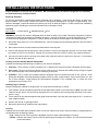
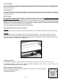
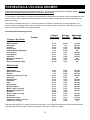
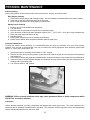
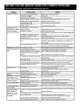
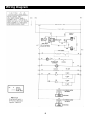
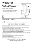
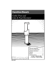
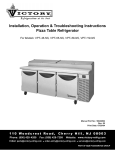
Refrigeration at its best
Installation, Operation and Troubleshooting Instructions
Reach-In & Pass-Thru Warmer/Refrigerator
For Models: HR-1D-7-EW, HR-1D-7-EW-PT, HR-2D-7-EW, HR-2D-7-EW-PT,
RH-2D-7-EW & RH-2D-7-EW-PT
Manual Part No. XXXXXXXX
Rev: 00
Print Date: xx/xx/xx
110 Woodcrest Road,
Phone: (856) 428- 4200
Cherry Hill, NJ 08003
Fax: (856) 428-7299
E-Mail: [email protected]
●
Website: www.victory-refrig.com
[email protected]
●
[email protected]
PART OF AGA FOODSERVICE GROUP
T
H
A
N
K
Y
O
U
Thank you for purchasing a Victory Refrigeration Warmer / Refrigerator! This unit has
passed our strict Quality Control Inspection and meets the high standards set by
Victory Refrigeration.
You have made a quality investment that with proper
maintenance will give you years of service.
Please read the following installation and maintenance instructions before installing or
using your unit.
If you have any questions, please call our Customer Service
Department at (856) 428-4200.
IMPORTANT INFORMATION - PLEASE READ
●
Please read these instructions carefully before installing or using. If recommended
procedures are not followed, warranty claims will be denied.
●
Your Warranty Registration information is located on the next page of this manual. Please
complete the card and submit it to Victory Refrigeration within 10 days of installation.
Failure to properly register equipment can void the warranty.
●
Victory Refrigeration reserves the right to change specifications and product design
without notice. Such revisions do not entitle the buyer to corresponding
changes, improvements, additions or replacements for previously purchased equipment.
●
A detailed Owners Manual with a troubleshooting guide, parts lists and additional
information can be ordered from the factory or may be downloaded free from the website at
www.victory-refrig.com.
Warranty
(Continental USA Only)
The Seller warrants to the original purchaser, equipment manufactured by Seller to be free from defects in material and
workmanship for which it is responsible. The Seller's obligation under this warranty shall be limited to replacing or
repairing at Seller's option, without charge, F.O.B. Sellers factory, any part found to be defective and any labor and
material expense incurred by Seller in repairing or replacing such part, such warranty to be limited to a period of one
year from date of purchase or thirteen months from date of shipment from Seller's factory, whichever is earlier, provided
terms of payment have been fully met. All labor shall be performed during regular working hours. Overtime premium
charges will be at Buyer's expense.
Proof of purchase must be supplied to Seller to validate warranty. This warranty is valid only if equipment is properly
installed, started-up and inspected by the dealer or authorized Victory Service agent.
Removal or alteration of the serial/data plate from any equipment shall be deemed to release Seller from all warranty
obligations or any other obligations, expressed or implied.
This warranty does not cover Thermostat or Defrost Timer calibration and/or adjustment, freight damage, normal
maintenance items outlined in Owner's Manual, adjustment of door mechanisms or replacement of light bulbs, fuses
or batteries.
Any repairs or replacement of defective parts shall be performed by Seller's authorized service personnel. Seller shall
not be responsible for any costs incurred if the work is performed by other than Seller's authorized service personnel.
Reimbursement claims for part(s) or labor service costs must be made in writing. Model, cabinet serial numbers and
installation location must be shown on the claim. A receipted bill from the servicing agency must accompany the claim,
together with full details of the service problems, diagnosis and work performed. Victory reserves sole discretion
whether further documentation on a claim is to be submitted.
Seller shall not be liable for consequential damages of any kind which occur during the course of installation of
equipment, or which result from the use or misuse by Buyer, its employees or others of the equipment supplied
hereunder, and Buyer's sole and exclusive remedy against Seller for any breach of the foregoing warranty or otherwise
shall be for the repair or replacement of the equipment or parts thereof affected by such breach.
The foregoing warranty shall be valid and binding upon Seller if and only if Buyer loads, operates and maintains the
equipment supplied hereunder in accordance with the instruction manual provided to Buyer. Seller does not guarantee
the process of manufacture by Buyer or the quality of product to be produced by the equipment supplied hereunder
and Seller shall not be liable for any prospective or lost product or profits of Buyer.
THE FOREGOING WARRANTY IS EXCLUSIVE AND IN LIEU OF ALL OTHER EXPRESS AND IMPLIED
WARRANTIES WHATSOEVER. SPECIFICALLY THERE ARE NO IMPLIED WARRANTIES OF MERCHANTABILITY
OR OF FITNESS FOR A PARTICULAR PURPOSE.
The foregoing shall be Seller's sole and exclusive obligation and Buyer's sole and exclusive remedy for any action,
whether in breach of contract or negligence. In no event shall Seller be liable for a sum in excess of the purchase price
of the item.
You may register online at www.victory-refrig.com, fax this completed page to (856) 428-7299, or copy and mail form below to Victory.
*NOTE: The following mail-in form or online registration must be filled out and forwarded to Victory by the installer or customer within 10 days
after start-up. Failure to do this will invalidate the warranties. Retain this information for your records.
110 WOODCREST ROAD
CHERRY HILL, NJ 08003-3648
TEL: (856) 428-4200 ● FAX: (856) 428-7299
WARRANTIES NOT VALID UNLESS REGISTERED AT
FACTORY WITHIN 10 DAYS AFTER START-UP DATE.
Cabinet Model No.______________________
Cabinet Serial No._________________
(Data plate information located inside cooler on
the upper left wall)
ORIGINAL DATE OF INSTALLATION __________________________________________________________________
INSTALLATION COMPANY NAME ____________________________________________________________________
STREET _______________________________ CITY _____________________ STATE ______ ZIP CODE___________
DISTRIBUTOR’S NAME_____________________________________________________________________________
STREET _______________________________ CITY _____________________ STATE ______ ZIP CODE___________
INSTALLATION INSTRUCTIONS
Proper installation is the first step to operation. We recommend that your warmer/ refrigerator be installed by
an authorized Victory Certified Installer.
Receiving Shipment
All units are performance tested and thoroughly inspected prior to shipment. Upon leaving the factory, all units are in
perfect condition. Upon receipt, examine the exterior of the shipment packaging for any signs of rough handling. If the
cabinet is damaged, it should be noted on the delivery slip or bill of lading and signed. A claim must be filed immediately
against the carrier indicating the extent and estimated cost of damage incurred.
Uncrating
Tools Needed : 3/4” Box Wrench
●
Adjustable Wrench
●
Level
WARNING: Never lay your warmer / refrigerator down on either its back, front or sides. This allows compressor oil into the
refrigerant lines which can damage the compressor at start-up. If the unit is laid down, it must be set upright for a minimum
of 12 hours before starting the compressor. Failure to adhere to the above recommendation will void the warranty.
1. Split plastic wrap along one of the cardboard posts. Remove and discard all packaging material, tape and interior
components.
2. Move cabinet as close to final location as possible before removing skid.
3. Remove the shipping skid by tipping the cabinet forward. Remove the shipping bolts with 3/4” box wrench while
the cabinet is held in one direction. Repeat this procedure while the cabinet is held in the opposite direction.
4. Use extreme caution when removing the wooden skid, especially when the last bolt is removed. If not properly
blocked, the skid will fall to the floor.
Locating Your New Storage Warmer/ Refrigerator
Consider the following when selecting a location for your warmer / refrigerator:
1. Clearance - There must be a minimum clearance of 10” between the top of the warmer / refrigerator and the ceiling.
2. Floor Load - The floor on which the cabinet will rest must be free of vibration and suitably strong enough to support
the combined weights of the cabinet plus the maximum product load.
3. Ventilation - The air cooled, self-contained warmer / refrigerator requires a sufficient amount of cool, clean air. Avoid
placing the refrigerator near heat generating equipment such as ovens, ranges, heaters, fryers, steam kettles, etc., and
out of direct sunlight. Avoid locating the self-contained refrigerator in an unheated room, or where the room
temperature may be below 55 °F.
Installing Legs or Casters
Warmer / Refrigerator cabinets are shipped with 1/2” single stud mounted legs or casters.
1. Legs / Casters must be screwed by hand into the threaded holes located on the case bottom (*Note: Once the caster
cannot be turned, take a 3/4” box wrench and tighten the nut in between the mounting plate and wheel of the caster
until it is snug).
2. Tilt the cabinet in one direction approximately eight inches and block it securely with several pieces of 2 x 4 lumber or
other suitable material.
3. Screw in the two left or right legs /casters.
4. Repeat this procedure to install the other legs /casters.
Leveling
Cabinets must be leveled when installed. Failure to level your cabinet may result in doors not sealing, closing properly or
condensate water not draining properly.
Legs - Rotate the foot of the leg with an adjustable wrench to achieve desired height for leveling.
Casters - Cabinets with casters can be leveled by placing large flat washers in between 1/2” stud and holes located
on the case bottom.
1
Cabinet Cleaning
Prior to placing your new warmer / refrigerator and all shelves, pans and slides into operation, it is advisable that the
interior be washed thoroughly with a mild detergent and water solution. Rinse with clear water and a sanitizing solution.
Allow cabinet to air dry.
Installing Shelves
All cabinets with shelves are supplied with pilasters and shelf clip supports. Shelves are easily installed by inserting the
shelf support clips into the pilasters so they fit tightly. Align the shelf so the smaller fill wires run from front to rear and rest
the shelf on the clips.
Electric Supply
Wiring should be done by a qualified electrician in accordance with local electrical codes. A separate ground wire must
be supplied for all installations. A properly wired warmer / refrigerator will assure proper operation. Electrical supply
requirements are on the cabinet serial/data plate. It is recommended that a direct, properly protected line of the proper
size wire be installed from the main supply to your warmer / refrigerator. To assure that the correct voltage is being
supplied, while the warmer / refrigerator is in operation take a voltage reading at the motor-compressor electrical
connections, or as close to the motor-compressor as possible.
All warmer / refrigerator electrical systems are internally grounded.
Installing Replacement Door Gasket (if required)
Removing
Beginning at one corner, pry gasket loose from the retaining strip. Peel remainder of gasket from the door and discard.
Replacing
Before replacing, be sure the gasket and door are at room temperature. (If necessary, soak the gasket in
warm water to make it more pliable.) Align new gasket frame on the door retainer strip. Starting at one corner,
press each corner of the gasket into the retainer strip. Once started, the gasket can be easily inserted around the entire
perimeter of the door by simply press rolling into place.
“Door Gasket & Retainer Strip”
Temperature Control
The refrigerator temperature control should be set to maintain a temperature of 38°F (3.3°C) to 40°F (4.4°C).
The warmer temperature control can be adjusted to desired temperature of 80°F (26.7°C) to 180°F (82.2°C). See
recommended food storage period chart on page 5.
Digital Thermometer Back-Up Battery
Prior to cabinet start up, make sure that a 9 Volt battery is connected. This will keep the digital
thermometer operational during an
unexpected power failure.
2
Digital Thermometer
Digital display thermometers have a sensing range of -40°F to 220°F (-40°C to 105°C) which allows it to be used in a wide
variety of applications. Setting the Alarm Control for proper application is accomplished by installing the jumper on the "HI"
(High temperature alert for Refrigerators and Freezers) or "LO" (Low Temperature alert for Warmers) pin position as
shown:
Calibrating Digital Thermometer Display Temperature
The alarm switch must be placed in the right (T) position as shown when calibrating temperature.
*Note: The digital thermometer has a built-in delay to display change every two (2) minutes. This prevents the display from
showing erratic temperature readings during door openings. When making any calibration adjustments, allow two minutes
for the delay to register temperature changes.
Place a reliable dial or digital thermometer sensing device in the center area of the cabinet. Turn the temperature
calibration screw clockwise to increase the temperature, or counter-clockwise to decrease the temperature. Wait two
minutes for the display to respond to the new settings.
Setting Digital Thermometer Alarm
Move the alarm switch to the left (AL) position. (The Display may begin to Flash.)
Turn alarm adjusting screw clockwise to increase the setting or counter-clockwise to decrease.
Set the temperature to the appropriate range for the application as shown above.
Move the alarm switch to the right (T) position.
Note: The alarm is indicated by a flashing display temperature and occurs when temperatures rise above the alarm setting
for refrigerators and freezers, or when temperatures drop below the alarm setting for warmers. Changing the jumper to
read in "Centigrade" will not require further calibration or alarm adjustment.
3
Dial Thermometer Calibration
1. Check cabinet temperature by using an accurate hand held dial or digital thermometer.
2. Look at the dial thermometer on the cabinet grille, if it matches the thermometer test meter (+ or -1°F)do not
adjust.
3. It it does not match, remove the dial thermometer lens with a small screwdriver.
4. To adjust the temperature needle, insert a small screwdriver in the slotted screw on the needle.
5. Hold the wide end of the needle to keep it from moving, and turn the screw clockwise or counterclockwise to
adjust as needed.
*Note: Temperature settings should be as follows; refrigerator set at 38°°F (3.3°°C) and warmers set at 180°°F
(82. 2°°C).
6. Release needle and remove screwdriver.
7. Verify new needle setting with thermometer test meter.
8. Replace dial thermometer lens.
Installation Checklist
After the cabinet has been installed, leveled and cleaned as described, refer to the following checklist prior to start-up.
Check for proper electrical hook-up.
Check exposed refrigeration line connections for leaks. Make sure refrigeration lines are not dented, kinked or rubbing.
Check condenser fan for freedom to rotate without striking any stationary members.
Check that cabinet is level.
Product Load
After the warmer / refrigerator has been started and reaches the proper storage temperatures, food may be loaded. For
optimum energy efficiency, we recommend allowing a 1-1/2” clearance between the interior cabinet wall and product load.
4
PREHEATING & UTILIZING WARMER
Preheat the warmer section one hour before placing food. The food should be placed in the cabinet while hot, but not
until it stops giving off steam (if excessive, use a lid on pots or pans).
It is necessary to experiment by increasing and decreasing the temperature of the warmer until the temperature at which
majority food is in best condition has been discovered. Once the setting is determined, the control should always be
kept at this setting.
Foods such as breaded meats, fish, etc require less degree of moisture in the warmer to prevent sogginess. All
warmer sections are equipped with vents or a damper. The damper should be opened for such food by turning the
knob in the desired direction for opening and closing.
Recommended Food Storage Periods
Product
Longest
Time Kept
Average
Time Kept
Approximate
Temp. (°F)
2 hrs.
2 hrs.
8 hrs.
6 hrs.
1 hr.
6 hrs.
6 hrs.
8 hrs.
6 hrs.
6 hrs.
10 hrs.
30 min.
1 hr.
5 hrs.
3 hrs.
30 min.
3 hrs.
2 hrs.
4 hrs.
4 hrs.
3 hrs.
5 hrs.
170-180
140-150
140-150
170-180
160
170-180
170-180
140-150
160
170-180
150
8 hrs.
3 hrs.
1 hr.
8 hrs.
6 hrs.
5 hrs.
6 hrs.
4 hrs.
8 hrs.
3 hrs.
4 hrs.
8 hrs.
12 hrs.
4 hrs.
4 hrs.
4 hrs.
6 hrs.
3 hrs.
4 hrs.
2 hrs.
30 min.
4 hrs.
4 hrs.
3 hrs.
3 hrs.
2 hrs.
4 hrs.
2 hrs.
2 hrs.
3 hrs.
4 hrs.
2 hrs.
2 hrs.
2 hrs.
2 hrs.
2 hrs.
170-180
170-180
150-175
170-180
180
170-180
160-175
170-180
150-180
160-180
170-180
140-150
*Crispy or Dry Foods
Baked Potatoes
Corn Sticks
Crackers
Chicken Pies
Club Sandwiches (Wrapped)
Fried Chicken
Fried Seafood
Hard Rolls
Hot Mince or Apple Pie
Meat Pies
Popcorn and Potato Chips
*Moist Foods
Baked Beans
Baked Stuff Lobster
Biscuits
Casserole (without top crust)
Chop Suey
Deviled Crabs
Frankfurter
Hash
Hot Puddings
Mashed Potatoes
Meats - ready for serving
Muffins and Corn Bread
Soft Rolls
Stews - ready for serving
Sweet Rolls
Stuffed Pork Chops
Vegetables - ready for serving
Turkey with Dressing
170-180
140-150
170-180
170-180
175
Rolls that are extremely rich in butter content cannot be kept for any extended time without the butter becoming rancid.
Rolls with sugar icing may require a lower temperature to prevent the icing from running.
5
PERIODIC MAINTENANCE
6
Cabinet Cleaning
Victory Refrigeration recommends periodic internal and exterior cleaning as outlined below.
Daily Exterior Cleaning
1. Clean surface with a sponge and cleaning solution. Use a non-abrasive cleaner that does not contain chlorine.
2. Polish with a soft cloth, wiping with the grain of the metal.
3. Once a week wipe with a film cutting agent to maintain shine.
Weekly Interior Cleaning
1. Remove all food, food related items and shelves.
2. Turn the unit off.
3. Remove loose food particles from interior floors, walls and ceiling.
4. Scrub all interior surfaces with warm detergent solution 100 °F - 120°F (38°C - 39°C) and a nylon bristled brush.
5. Rinse with clear water and allow to air dry.
6. Reinstall shelves.
7. Return power (electrical) to unit by resetting circuit breaker.
8. Return food to cabinet when temperature indicator reaches safety zone.
Condenser Maintenance
To keep your cabinet running efficiently, it is recommended that you clean the condenser once every three months.
However, once a month is recommended if the unit is located near cooking equipment which produces grease laden
vapors, i.e. fryers, grills, steam kettles, etc.
1. Disconnect power by switching circuit breaker to “OFF” position.
2. Remove the front grill by removing the two (2) screws on the inside of the grill at each end, then lift the panel up
and straight out.
3. Use a vacuum cleaner with proper brush attachments to clean the condenser, motor-compressor and related parts.
4. In extreme cases of dust and grease buildup, the condenser fins may require blowing out with compressed air or
cleaning with a degreasing agent.
5. Turn circuit breaker to “ON” position.
WARNING: Failure to keep condenser clean may cause premature failure of motor-compressor which
will NOT be covered by warranty.
Lubrication
Unless otherwise specified, all Victory refrigerators are equipped with oilless type motors. The motor-compressor is a
sealed unit and is constantly lubricated when in operation. The condenser and the evaporator motors are equipped with
lifetime oiled bearings which never need to be oiled.
6
BEFORE CALLING SERVICE GUIDE FOR COMMON PROBLEMS
Caution: Disconnect Power Supply Prior to Attempting Any Service!
7
Wiring Diagram
8
Victory Refrigeration Inc
110 Woodcrest Road
Cherry Hill, NJ 08003-3648
Tel: (856) 428-4200
Fax: (856) 428-7299
Web: www.victory-refrig.com
E-mail: service@ victory-refrig.com
or
[email protected]