1
MODEL
463225312
Sears
item
No, 16167
Sears
Model
Performance
No, 415,16167210
T-46D
IMPORTANT: Fill out the product record information below.
Serial Number
See ratinglabel on grill for serialnumber.
Date Purchased
Forsupportandto registeryour
grill, pleasevisit us at
www.charbroil.com
If you havequestionsor need
assistanceduringassembly,
pleasecall 1-888-430-7870.
©2011 Char-Broil, LLC Columbus,GA 31902
Printed in China
Assembly instructions©2011
08/09/11 QG519-001-180801
For Your Safety ....................................
2-3
Use and Care .....................................
4-9
Limited Warranty ....................................
10
Parts List ..........................................
11
Parts Diagram ......................................
12
Assembly .......................................
13-24
Troubleshooting ..................................
25-27
Registration Card ...................................
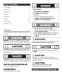
If you smell gas:
1. Shut off gas to the appliance.
2. Extinguish any open flame.
3. Open lid.
4. If odor continues, keep away from the
appliance and immediately call your gas
supplier or your fire department.
31
Safety Symbols
The symbols and boxes shown below explain what each heading
means. Read and follow all of the messages found throughout
the manual.
1. Do not store or use gasoline or other
flammable liquids or vapors in the vicinity of
this or any other appliance.
2. An LP cylinder not connected for use shall not
be stored in the vicinity of this or any other
appliance.
WARNING:
WARNING: Indicates an potentially hazardous situation
which, if not avoided, could result in death or serious injury.
CAUTION
CAUTION: Indicatesa potentially hazardous situation or
unsafe practicewhich, if not avoided, may result in minor
or moderate injury.
Failure to follow all manufacturer's instructions could result
in serious personal injury and/or property damage.
CAUTION
For residential use only. Do not use for commercial
cooking.
CAUTION:
DANGER: Indicates an imminently hazardous situation
which, if not avoided, will result in death or serious injury.
Read and follow all safety statements, assembly
instructions, and use and care directions before attempting
to assemble and cook.
CAUTION:
INSTALLER/ASSEMBLER:
Leave this manual with consumer.
CONSUMER:
Keep this manual for future reference.
Some parts may contain sharp edges.
Wear protectivegloves if necessary.
CAUTION
CALIFORNIA PROPOSITION 65
1. Combustion by-products produced when using
this product contain chemicals known to the State of
California to cause cancer, birth defects, and other
reproductive harm.
2. This product contains chemicals, including lead
and lead compounds, known to the State of
California to cause cancer, birth defects or other
reproductive harm.
Wash your hands after handling this product.
Installation Safety Precautions
• Use grill, as purchased, only with LP (propane) gas and the
regulator/valve assembly supplied. If your grill is Dual Fuel ready,
a conversion kit must be purchased for use with natural gas.
• Grill installation must conform with local codes, or in their
absence of local codes, with either the National Fuel Gas
Code, ANSI Z223.1/NFPA 54, Natural Gas and Propane
Installation Code, CSA B149.1, or Propane Storage and
Handling Code, B 149.2.
• All electrical accessories (such as rotisserie) must be
electrically grounded in accordance with local codes, or
National Electrical Code, ANSI/NFPA 70 or Canadian
Electrical Code, CSA C22.1. Keep any electrical cords and/or
fuel supply hoses away from any hot surfaces.
• This grill is safety certified for use in the United States and/or
Canada only. Do not modify for use in any other location.
Modification will result in a safety hazard.
Do not attempt to repair or alter the
hose/valve/regulator for any "assumed" defect. Any
modification to this assembly will void your warranty
and create the risk of a gas leak and fire. Use only
authorized replacement parts supplied by
manufacturer.
NOTE: DO NOT over tighten screws and
washers that come into contact with porcelain
coated surfaces, Over tightening may cause the
porcelain coating to crack and break, resulting in
exposed metal that will be prone to rust,
Using pots larger than 6 quarts in capacity could
exceed weight limit of the
side burner shelf
or side shelf,
resulting in failure
of grill cart
components.
LP Cylinder
•The LP cylinder used with your grill must meet the
following requirements:
•Use LP cylinders only with these required measurements: 12"
(30.5cm) (diameter) x 18" (45.7 cm) (tall) with 20 lb. (9 kg.)
capacity maximum.
• NEVERstore a spare LP cylinder under or near
the appliance or in an enclosed area.
•LP cylinders must be constructed and marked in accordance
with specifications for LP cylinders of the U.S. Department of
Transportation (DOT) or for Canada, CAN/CSA-B339,
cylinders, spheres and tubes for transportation of dangerous
goods. Transport Canada (TC). See LP cylinder collar for
marking.
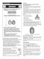
•LP cylinder valve must have:
•Type 1 outlet compatible with
regulator or grill.
•Safety relief valve.
•UL listed Overfill Protection
OPDHandWheel
Device (OPD). This OPD safety
feature is identified by a unique triangular hand wheel. Use
only LP cylinders equipped with this type of valve.
•LP cylinder must be arranged for vapor withdrawal and include
collar to protect LP cylinder valve. Always keep LP cylinders in
upright position during use, transit or storage.
• Never fill a cylinder beyond 80% full.
• An over filled or improperly stored cylinder is a
hazard due to possible gas release from the
safety relief valve. This could cause an intense
fire with risk of property damage, serious injury or
death.
If you see, smell or hear gas escaping,
immediately get away from the LP
cylindedappliance and call your fire department.
LP Cylinder Removal, Transport and Storage
•Turn OFF all control knobs and LP cylinder valve. Turn coupling
nut counterclockwise by hand only - do not use tools to
disconnect. Loosen cylinder screw beneath bottom shelf or
disconnect other retention means, then lift PL cylinder up and
and out of cart. Install safety cap onto LP cylinder valve.
Always use cap and strap supplied with valve.
Failure to use safety cap as directed may result in serious
personal injury and/or property damage.
•Adisconnected LP cylinder in LPCylinder
storage or being transported
must have a safety cap installed (as shown).
Do not store an LP cylinder in enclosed spaces
such as a carport, garage, porch, covered
patio or other building. Never leave an LP cylinder
Safety
inside a vehicle which may become overheated
Cap
by the sun.
Retainer Strap
•Do not store an LP cylinder in an area where children play.
_i
iiii¸;iiii!!
LP cylinder in upright position for vapor withdrawal
LP (Liquefied
Petroleum Gas)
•LP gas is nontoxic, odorless and colorless when produced. For
Your Safety, LP gas has been given an odor (similar to rotten
cabbage) so that it can be smelled.
•LP gas is highly flammable and may ignite unexpectedly when
mixed with air.
LP Cylinder Filling
•Use only licensed and experienced dealers.
•LP dealer must purge new cylinder before filling.
•Dealer should NEVER fill LP cylinder more than 80% of LP
cylinder volume. Volume of propane in cylinder will vary by
temperature.
•A frosty regulator indicates gas overfill. Immediately close LP
cylinder valve and call local LP gas dealer for assistance.
•Do not release liquid propane (LP) gas into the atmosphere.
This is a hazardous practice.
•To remove gas from LP cylinder, contact an LP dealer or call a
local fire department for assistance. Check the telephone
directory under "Gas Companies" for nearest certified LP
dealers.
LP Cylinder Exchange
Connecting Regulator to the LP Cylinder
•Many retailers that sell grills offer you the option of replacing
your empty LP cylinder through an exchange service. Use only
those reputable exchange companies that inspect, precision fill,
test and certify their cylinders. Exchange your cylinder only
for an OPD safety feature-equipped cylinder as described
in the "LP Cylinder" section of this manual.
1.LP cylinder must be properly secured onto grill. (Refer to
assembly section.)
•Always keep new and exchanged LP cylinders in upright
position during use, transit or storage.
2.Turn all control knobs to the OFF position.
3.TurnLP cylinder OFF by turning hand-wheel clockwise to a
full stop.
4.Remove the protective cap from LP cylinder valve. Always use
cap and strap supplied with valve.
•Leak test new and exchanged LP cylinders BEFORE
connecting to grill.
•Place dust cap on cylinder valve outlet whenever the cylinder is
not in use. Only install the type of dust cap on the cylinder valve
outlet that is provided with the cylinder valve. Other types of caps
or plugs may result in leakage of propane.
LP Cylinder Leak Test
For your safety
•Leak test must be repeated each time LP cylinder is exchanged
or refilled.
OPDHandWheel
j
Safety Relief Valve
•Do not smoke during leak test.
•Do not use an open flame to check for gas leaks.
•Grill must be leak tested outdoors in a well-ventilated area,
away from ignition sources such as gas fired or electrical
appliances. During leak test, keep grill away from open flames
or sparks.
!
Strap and Cap
•Use a clean paintbrush and a 50/50 mild soap and water
solution. Brush soapy solution onto areas indicated by arrows
in figure below.
Do not use a POL transport plug
(plastic part with external threads)!
It will defeat the safety feature of
the valve.
A Do not use household cleaning agents. Damage to gas
train components can result.
5.Hold regulator and insert nipple into LP
cylinder valve. Hand-tighten the
coupling nut, holding regulator in a
straight line with LP cylinder valve so
as not to cross-thread the connection.
Nipple has to be centered
intothe LP cylinder valve.
If "growing" bubbles appear do not use or move the LP
cylinder. Contact an LP gas supplier or your fire
department!
Type 1 outlet with
thread on outside
Leak Testing Valves, Hose and Regulator
1.Turn all grill control knobs to OFF.
2.Be sure regulator is tightly connected to LP cylinder.
3.Completely open LP cylinder valve by turning hand wheel
counterclockwise. If you hear a rushing sound, turn gas off
immediately. There is a major leak at the connection. Correct
before proceeding.
Hold coupling nut and regulator
as shown for properconnection
to LP cylinder valve.
4.Brush soapy solution onto areas circled below, or other similar
fittings on your grill.
6.Turn the coupling nut clockwise and tighten to a full stop. The
regulator will seal on the back-check feature in the LP cylinder
valve, resulting in some resistance. An additional one-half to
three-quarters turn is required to complete the
connection. Tighten by hand only - do not use tools.
NOTE:
If you cannot complete the connection, disconnect regulator and
repeat steps 5 and 6. If you are still unable to complete the
connection, do not use this regulator!
Do not insert any tool or foreign object into the valve
outlet or safety relief valve. You may damage the valve
and cause a leak. Leaking propane may result in
explosion,fire, severe _ersonal injury, or death.
Outdoor gas appliance is not intended to be installed
in or on a boat.
Outdoor gas appliance is not intended to be installed
in or on an RV.
, Never attempt to attach this grill to the self-contained
LP gas system of a camper trailer or motor home.
, Do not use grill until leak-tested.
, If a leak is detected at any time, STOP and call the fire
department.
, If you cannot stop a gas leak, immediately close
LP cylinder valve and call LP gas supplier or your fire
department!
5.If "growing" bubbles appear, there is a leak. Close LP
cylinder valve immediately and retighten connections. If leaks
cannot be stopped do not try to repair. Call for replacement
parts.
6.Always close LP cylinder valve after performing leak test by
turning hand wheel clockwise.
For Safe Use of Your Grill and to Avoid Serious
injury:
• Do not let children operate or play near grill.
• Keep grill area clear and free from materials that burn.
• Do not block holes in sides or back of grill.
• Check burner flames regularly.
• Use grill only in well-ventilated space. NEVER use in
enclosed space such as carport, garage, porch,
covered patio, or under an overhead structure of any
kind.
• Do not use charcoal or ceramic briquets in a gas grill.
(Unless briquets are supplied with your grill.)
• Do not cover grates with aluminum foil or any other
material. This will block burner ventilation and create
a potentially dangerous condition resulting in
property damage and/or personal injury.
" Use grill at least 3 ft. from any wall or surface.
Maintain 10 ft. clearance to objects that can catch fire
or sources of ignition such as pilot lights on water
heaters, live electrical appliances, etc.
Safety Tips
A Before opening LP cylinder valve, check the coupling nut for
tightness.
A When grill is not in use, turn off all control knobs and LP
cylinder valve.
,A, Never move grill while in operation or still hot.
A Use long-handled barbecue utensils and oven mitts to avoid
burns and splatters.
,A, Maximum load for sideburner and side shelf is 10 Ibs.
A The grease tray or cup must be installed during use and
emptied after each use. Do not remove grease tray or cup
until grill has completely cooled.
A Clean grill often, preferably after each cookout. If a bristle
brush is used to clean any of the grill cooking surfaces,
ensure no loose bristles remain on cooking surfaces prior to
grilling. It is not recommended to clean cooking surfaces
while grill is hot.
A If you notice grease or other hot material dripping from grill
onto valve, hose or regulator, turn off gas supply at once.
Determine the cause, correct it, then clean and inspect valve,
hose and regulator before continuing. Perform a leak test.
A Keep ventilation openings in cylinder enclosure (grill cart) free
and clear of debris.
A Do not store objects or materials inside the grill cart
enclosure that would block the flow of combustion air to the
underside of either the control panel or the firebox bowl.
A The regulator may make a humming or whistling noise during
operation. This will not affect safety or use of grill.
,A, If you have a grill problem see the "Troubleshooting Section".
A If the regulator frosts, turn off grill and LP cylinder valve
immediately. This indicates a problem with the cylinder and it
should not be used on any product. Return to supplier!
tAuT,oN
i" Putting out grease fires by closing the lid is not possible.
Grills are well ventilated for safety reasons.
• Apartment Dwellers:
Check with managementto learn the requirements
and fire codes for using an LP gas grill in your
apartment complex. If allowed, use outside on the
ground floor with a three (3) foot clearance from walls
or rails. Do not use on or under balconies.
• NEVER attempt to light burner with lid closed.A
buildup of non-ignited gas inside a closed grill is
hazardous.
• Never operate grill with LP cylinder out of correct
position specified in assembly instructions.
• Always close LP cylinder valve and remove
coupling nut before moving LP cylinder from
specified operation position.
i" Do not use water on a grease fire. Personal injury may
result. If a grease fire develops, turn knobs and LP
cylinder off.
i, Do not leave grill unattended while preheating or burning
off food residue on HI. if grill has not been regularly
cleaned, a grease fire can occur that may damage the
product. Follow instructions on General Grill Cleaning
and Cleaning The Burner Assembly to prevent grease fires.
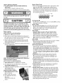
ignitor Lighting
A Do not lean over grill while lighting.
1. Turn OFF gas burner control valves.
2. Turn ON gas at LP cylinder.
3. Open lid during lighting.
4. To ignite, push and turn ignition burner knob to HI.
5. Push and hold ELECTRONIC iGNITION button until the burner
lights.
6. If ignition does NOT occur in 5 seconds, turn the burner
controls OFF, wait 5 minutes and repeat the lighting
procedure.
7. To ignite remaining burners, turn knob to the HI position
starting with the burners closest to IGNITION BURNERS first.
If ignitor does not work, follow match lighting instructions.
Lighting instructions are continued on the next page
Ignitor Lighting (continued)
8. For grills equipped with ELECTRONIC IGNITION at
each burner:
Repeat steps 4 through 6 to light each burner.
9. Once each burner has ignited, turn knobs to desired setting.
Burner Flame Check
• Remove cooking grates and flame tamers. Light burners, rotate
knobs from HI to LOW. You should see a smaller flame in
LOW position than seen on Hi. Perform burner flame check
on sideburner, also. Always check flame prior to each use. If
only low flame is seen refer to "Sudden drop or low flame" in
the Troubleshooting Section.
Turn controls and gas source or tank OFF when not
in use.
CAUT,o.
if ignition does NOT occur in 5 seconds,
burner controls
lighting
turn the
OFF, wait 5 minutes and repeat the
procedure.
If the burner does not ignite with
the valve open, gas will continue to flow out of the
burner and could accidently ignite with risk of injury.
Match-Lighting
,& Do not lean over grill while lighting.
1. Open lid. Turn ON gas at LP cylinder.
2. Place match into match holder (hanging from side panel of
grill). Light match; then light burner by placing match through
the match light hole on right or left side of grill.
3. Push in and turn far right or far left burner knob to the HI
position, depending on match light hole selected. Be sure
burner lights and stays lit.
4. Light adjacent burners in sequence by pushing knobs in and
turning to the HI position.
NOTE: Your grill may NOT be equipped with a Sideburner!
Sideburner ignitor Lighting
,A Do not lean over grill while lighting.
1. Open sideburner lid. Turn ON gas at LP cylinder.
2. Turn sideburner knob to the Hi position, push and hold
ELECTRONIC iGNiTOR button.
3. If sideburner does NOT light within 5 seconds, turn knob to OFF,
wait 5 minutes, then
repeat lighting procedure.
Sideburner Match Lighting
1. Open sideburner lid. Turn ON
gas at LP cylinder.
2. Place lit match near burner.
3. Turn sideburner knob to the
HI position.
Be sure burner lights and
stays lit.
8
Turning Grill Off
• Turn all knobs to the OFFposition. Turn LP cylinder OFF by turning
hand-wheel clockwise to a full stop.
Ignitor Check
• Turn gas off at LP cylinder. Press and hold electronic ignitor
button. "Click" should be heard and spark seen each time
between each collector box or burner and electrode. See
"Troubleshooting" if no click or spark.
Valve Check
• Important: Make sure gas is off at LP cylinder before
checking valves. Knobs lock in OFF position. To check
valves, first push in knobs and release, knobs should spring
back. If knobs do not spring back, replace valve assembly
before using grill. Turn knobs to LOW position then turn back to
OFF position. Valves should turn smoothly.
Hose Check
Before each use, check to see if hoses are cut or worn or kinked.
Replace damaged hoses before using grill. Use only
valve/hose/regulator specified by manufacturer.
General Grill Cleaning
• Do not mistake brown or black accumulation of grease and
smoke for paint. Interiors of gas grills are not painted at the
factory (and should never be painted). Apply a strong solution
of detergent and water or use a grill cleaner with scrub brush
on insides of grill lid and bottom. Rinse and allow to completely
air dry. Do not apply a caustic grill/oven cleaner to painted
surfaces.
• Plastic parts: Wash with warm soapy water and wipe dry.
A Do not use citrisol, abrasive cleaners, degreasers or a
concentrated grill cleaner on plastic parts. Damage to and
failure of parts can result.
• Porcelain surfaces: Because of glass-like composition, most
residue can be wiped away with baking soda/water solution or
specially formulated cleaner. Use nonabrasive scouring powder
for stubborn stains.
• Painted surfaces: Wash with mild detergent or nonabrasive
cleaner and warm soapy water. Wipe dry with a soft
nonabrasive cloth.
• Stainless steel surfaces: To maintain your grill's high quality
appearance, wash with mild detergent and warm soapy water
and wipe dry with a soft cloth after each use. Baked-on grease
deposits may require the use of an abrasive plastic cleaning
pad. Use only in direction of brushed finish to avoid damage.
Do not use abrasive pad on areas with graphics.
• Cooking surfaces: If a bristle brush is used to clean any of
the grill cooking surfaces, ensure no loose bristles remain on
cooking surfaces prior to grilling. It is not recommended to
clean cooking surfaces while grill is hot.
cAuTioN
3.
4.
f
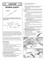
SPIDER
Remove carryover tubes and burners.
Detach electrode from burner.
NOTE: Removal/Detachment method will depend on the
burner configuration. See different configurations in
illustrations below.
ALERT!
5. Carefully lift each burner up and away from valve openings.
We suggest three ways to clean the burner tubes. Use the one
easiest for you.
(A) Bend a stiff wire (a light weight coat hanger works well)
into a small hook. Run the hook through each burner
tube several times.
r.._.,_
_-
(B) Use a narrow bottle brush with a flexible handle (do not
use a brass wire brush), run the brush through each
burner tube several times.
If you notice thatyour grill is getting hard to light or thatthe
flame isn't as strong as it should be, take the time to check and
clean the ventud's.
6.
(C) Wear eye protection: Use an air hose to force air into
the burner tube and out the burner ports. Check each
port to make sure air comes out each hole.
Wire brush entire outer surface of burner to remove food
residue and dirt.
7.
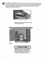
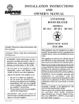
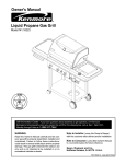
CONTROLPANEL
SPIDERWEBS
INSIDE VENTURI
BURNER
In someareasof the country,spidersor small insectshavebeen
knownto create"flashback"problems.The spidersspinwebs,build
nestsand layeggs in the grill'sventuritube(s)obstructingthe flow of
gasto the burner.Thebacked-upgascan ignitein the venturibehind
thecontrolpanel.This is knownasa flashbackand it candamage
yourgrill and evencauseinjury.
Clean any blocked ports with a stiff wire such as an open
paper clip.
8. Check burner for damage, due to normal wear and corrosion
some holes may become enlarged. If any large cracks or
holes are found replace burner.
VERY IMPORTANT:Burner tubes must reengage valve
openings. See illustrations at right.
9. Attach electrode to burner.
Correct
10. Carefully replace burners.
11. Attach burners to brackets on firebox.
12. Reposition carryover tubes and attach
to burners. Replace flame tamers and
cooking grates.
Topreventflashbacksand ensuregoodperformancethe burnerand
venturiassemblyshouldbe removedfrom the grill and cleaned
iiii....
foreusewheneverthe grill hasbeen idlefor an extendedperiod.)
J
Storing Your Grill
• Clean cooking grates.
• Store in dry location.
• When LP cylinder is connected to grill, store outdoors in a wellventilated space and out of reach of children.
__`_%i_i_i_!_i_i_i_i!_i_!_
Electrode
• Cover grill if stored outdoors. Choose from a variety of grill
covers offered by manufacturers.
• Store grill indoors ONLY if LP cylinder is turned off and
disconnected, removed from grill and stored outdoors.
• When removing grill from storage, follow "Cleaning the Burner
Assembly" instructions before starting grill.
Cleaning the Burner Assembly
Follow these instructions to clean and/or replace parts of burner
assembly or if you have trouble igniting grill.
1. Turn gas OFF at control knobs and LP cylinder,
2. Remove cooking grates and flame tamers.
a flat blade
screwdriver
This warranty only applies to units purchased fiom an authorized retailer. ManuPacturer warrants to the original cunsumer-purchaser only that this
product shall be fiec from defects in workmanship and materials alter correct assembly and under normal and reasonable home use for the periods
indicated below beginning on the date of purchase*. The manuPacturer reserves the right to require that defective parts be returned, postage and or
freight pre-paid by the consumer for review and examination.
SCOPE
OF COVERAGE
PERIOD
Burner
OF COVERAGE
TYPE
COVERAGE
PERFORATION, MANUFACTURING,
AND MATERIAL DEFECTS ONLY
3 ,/ears from date of purchase*
2 years from date of purchase*
l year from date of purchase*
Firebox
All Other Parts
OF FAILURE
*Note: A dated sales reciept WILL be required for walTanty service.
The
original
consumer-purchaser
will be responsible
for all shipping
charges
for parts replaced
under
the terms
of this limited
warranty.
This limited warranty is applicable in the United States and Canada only; is only available to the original owner of the product and is not transferable.
Manufacturer
requires proof of your date of purchase. Theretbre, you should retain your sales slip or invoice. Registering your product is not a
substitute for proof of purchase and the manuPacturer is not responsible for or required to retain proof of purchase records.
This limited wananty applies to the functionality
of the product ONLY and does not cover cosmetic issues such as scratches, dents, corrosions
discoloring
by heat, abrasive and chemical cleaners or any tools used in the assembly or installation
of the appliance, surt:ace rust, or the
discoloration
of stainless steel surfiaces.
RUST is not considered
a manufacturing
or materials
defect.
This limited
warranty
will not reimburse
you for the cost of any inconvenience,
food, personal
injury
or property
or
damage.
ITEMS MAN UFACTURER WILL NOT PAY FOR:
1. Shipping cost, standard or expedited, for warranty and replacement parts
2. Service calls to your home.
3. Repairs when your product is used for other than normal, single-family household or residential use.
4. Damage, failures, or operating difficulties resulting from accident, alteration, careless handling, misuse, abuse, fire, flood,
acts of God, improper installation or maintenance, installation not in accordance with electrical or plmnbing codes, or use
of products not approved by the manufacturer.
5. Any food loss due to product failures or operating difficulties.
6. Replacement parts or repair labor costs for units operated outside the United States or Canada.
7. Pickup and delivery of your product.
8. Repairs to parts or systems resulting from unauthorized modifications made to the product.
9. The removal and/or reinstallation of your product.
DISCLAIMER OF IMPLIED WARRANTIES and LIMITATION OF REMEDIES
Repair or replacement of defective parts is your exclusive remedy under the terms of this limited warranty. In the event of parts availability issues,
the manufacturer reserves the right to substitute like or similar parts that are equally functional.
Manufacturer will not be responsible for any consequential or incidental damages arising fiom the breach of either this limited warranty or any
applicable implied warranty; or for failure or damage resulting from acts of God, improper care and maintenance, grease fire, accident, alteration,
replacement of parts by anyone other than Manufacturer, misuse, transportation, commercial use, abuse, hostile environments (inclement weather,
acts of nature, animal tampering), improper installation or installation not in accordance with local codes or printed manufacturer instructions.
THIS LIMITED WARRANTY IS THE SOLE EXPRESS WARRANTY GIVEN BY THE MANUFACTURER.
NO PRODUCT PERFORMANCE
SPECIFICATION OR DESCRIPTION WHEREVER APPEARING IS WARRANTED BY MANUFACTURER EXCEPT TO THE EXTENT SET
FORTH IN THIS LIMITED WARRANTY. ANY IMPLIED WARRANTY PROTECTION ARISING UNDER THE LAWS OF ANY S'IWFE,
INCLUDING IMPLIED WARRANTY OF MERCHANTABILITY OR FITNESS FOR A PAt_FICULAR PURPOSE OR USE, IS HEREBY
LIMITED IN DURATION TO THE DURATION OF THIS LIMITED WARRANTY.
Neither dealers nor the retail establishment
selling this product
has any authority
to make any additional
warranties
in addition to or inconsistent
with those stated above.
Manufacturer's
maxhnum
liability,
in any event, shall not exceed
product paid by the original consumer.
or to promise
remedies
the purchase price of the
NOTE: Some states do not allow an exclusion or limitation of incidental or consequential damages, so some of the above limitations or exclusions
may not apply to you. This limited warranty gives you specific legal rights as set foth herein. You may also have other rights which vary from state
to state. In the state of California only; if refinishing or replacement of the product is not commercially practicable, the retailer selling this product or
the Manufacturer will refund the purchase price paid for the product, less the amount directly attributable to use by the original consumer-purchaser
prior to discovery of the nonconformity. In addition, in the state of California only; you may take the product to the retail establishment selling this
product in order to obtain performance under this limited wananty.
if you wish to obtain
performance
of any obligation
under
write to:
Consumer
Relations
P. O. Box 1240
this limited
warranty,
Columbus,
GA 31902-1240
Consumer returns will not be accepted unless a valid Return Authorization
is first acquired.
Authorized
the package with an RA number and the package is shipped freight/postage
pre-paid.
Consumer returns
refused.
you should
returns are clearly marked on the outside
that do not meet these standards will be
of
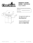
A
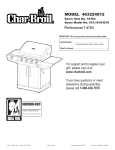
1
BOTTOM SHELF
B
1
TANK SCREW, F/BOTTOM
C
2
CASTER, LOCKING
D
2
CASTER, FIXED
E
1
CART LEFT SIDE PANEL
F
1
GROMMET, F/REGULATOR
G
1
H
OO
1
LOGO PLATE
PP
1
HARDWARE
QQ
RR
1
2
LEFT DOOR, NO HANDLE
DOOR HANDLE
SS
TT
1
4
RIGHT DOOR, NO HANDLE
FLAME TAMER
CART RIGHT SIDE PANEL
UU
3
COOKING GRATE
1
CART LOWER BACK PANEL
VV
1
G RATE, F/SB
I
1
FRONT BRACE
WW
1
WARMING RACK
J
1
LEFT RAIL, F/GREASE
XX
2
K
1
RIGHT RAIL, F/GREASE
ELECTRODE,
WIRE
L
1
FIREBOX
M
1
MATCH HOLDER
N
4
MAIN BURNER
O
2
ELECTRODE, F/MAIN BURNER, 900MM
WIRE
P
3
CARRYOVER TUBE W/COTTER
Q
1
IGNITER SWITCH MODULE
R
1
HOSE VALVE REGULATOR ASSEMBLY
S
1
MAIN CONTROL PANEL
T
1
ELECTRONIC IGNITION MODULE
U
1
CAP F/El MODULE
SHELF
HOLE
TRAY
TRAY
F/TOP LID ASSEMBLY
F/MAIN BURNER, 600MM
PIN
NOT Pictured
V
1
GREASE TRAY
W
1
ELECTRODE F/SIDEBURNER
...
2
DOOR MAGNET
X
1
ELECTRODE WIRE, F/SIDEBURNER
...
1
CASTER PIN
...
1
HARDWARE PACK
...
1
ASSEMBLY MANUAL, ENGLISH
Y
Z
5
5
BEZEL, F/CONTROL
CONTROL KNOB
KNOB
AA
1
CART UPPER BACK PANEL
...
1
ASSEMBLY MANUAL, SPANISH
...
1
CLEANING TOOL
BB
1
LEFT SIDE SHELF, F/SB
CC
1
FASCIA, F/LEFT SIDE SHELF
DD
1
DRIP PAN, F/SB
EE
4
RUBBER BUMPER, LID
FF
1
LID, F/SB
GG
1
SIDEBURNER BURNER
HH
1
RIGHT SIDE SHELF
II
JJ
1
1
FASCIA, F/RIGHT
TOP LID
KK
1
HANDLE F/TOP LID
LL
2
MM
1
NN
4
SIDE SHELF
RUBBER BUMPER, RECTANGLE, F/
TOP LID
HEAT SHIELD F/TANK
TEMPERATURE
MOUNTED
GAUGE, UFC
11
LL
WW
N
N
N
N
UU
UU
UU
O0
TT
TT
TT
TT
EE
vv
HH
GG
R
S
e_--Q
_i_
ii__iii>_
QC
RR
RR
F
H
B
A
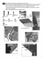
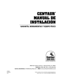
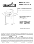
Place bottom shelf upside down. Insert Caster Pin into the caster mounting plate to lock it in place, shown A.
Spin the caster clockwise into the threads on the bottom shelf until secure. Remove the Caster Pin and
repeat for remaining casters. Make sure the two locking casters are secured at the rear and the non-locking
casters are secured at the front. After all 4 casters are secure, remove the Caster Pin and save for future
maintenance.
Nomlockcaster
Locking caster
Caster pin
Qty.1
Caster pin
Bottom shelf
i
Attach side panels to bottom shelf using
three 1/4-20x1/2" screws, 7mm lock
1/4-20x1/2" screw
1/4-20x1/2"screw
Oty.G
washers, and 7ram flat washers per panel.
IMPORTANT: Panel with large hole must
be on left side of bottom shelf.
7ram lock washer
Qty.G
7ram lockwasher
7ram fiat washer
7mm fiat washer
Qty.G
Left side panel
(with largehole)
Make sure side panels
are pushed as far to the
rear of bottom sheff as
possible before fully
tightening screws.
Right side panel
Magnets
13
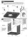
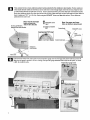
Place lower back panel between side panels at rear of bottom shelf. Secure lower back panel to side panels using
fourl14-20xl12" screws, 7ram lock washers, and 7ram flat washers.
1/4-20x1/2"screw
Lower backpanel
7ramlockwasher
7ram fiat washer
1/4-20x1/2"screw
Qty.4
,.."
7ram lockwasher
Qty.4
O
Qty.4
Tramfiat washer
......
"
................
This step requires two people
to lift and position grill head
onto cart. Carefully lower the grill
head onto the cart, aligning slots at
bottom of grill head with posts on
cart side panels. Make sure the
regulator hose is hanging outside
the cart. Grill head must face open
side of cart.
head
Regulator hose
14
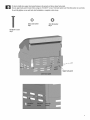
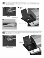
On back of grill, place upper back panel between side panels and above lower back panel.
Secure upper back panel in lower holes using one l/4-20xlV2" screw, 7ram lock washer and 7ram flat washer on each side.
Do not fully tighten screws until side shelf installation is complete in later steps.
7ramLockwasher
Qty.2
7ramflat washer
Qty.2
1/4-20x1Vz"screw
Qty.2
Upperbackpanel
15
NOTE: DO NOT over tighten screws and washers that come into contact with porcelain coated su#aces. Over tightening
may cause the porcelain coating to crack and break, resulting in exposed metal that will be prone to rust.
Insert flange on right side shelf into side shelf brackets on side of firebox.
Attach right side shelf using three 114-20x314"screws, 7mm rock washers, 7ram fiat washers and 114"nuts, shown A.
Attach rear of shelf using one l/4-20xlY2" screw, 7ram rock washer and 7ram fiat washer in rower hole, shown B.
Attach front of shelf and fascia using one #8x3/8" serf-tapping screw and large fiat washer, shown C.
Attach front of shelf and fascia using one 114-20x314"screw, 7ram lock washer, 7ram fiat washer and 114" nut, shown D/C.
1/4-20xlYz" screw
Qty.1
Qty.41/4"20x3/4"
screw
#8x3/8"
7ram lock washer
self-tappingoty.1
screw
Oty.5
1/4" nut
7mmoty.sflat
washer
Oty.4
large fiat washer
Oty.1
1/4-20x1½"
screw
mrnlock
washer
7rnm flat
washer
7ram lock
washer
panel
16
Insert
flangeonleftsideburner
shelfintosideshelfbrackets
onsideoffirebox.
Attachleftsideburner
shelfusingthree1/4-20x3/4"
screws,
7mmlockwashers,
7mmflatwashers,
1/4"nuts,shown
A.
Attach
rearofshelfusingone1/4-20x1V2"
screw,
7mmlockwasher,
and7mmflatwasher
inlowerhole,shownB.
Attach
frontofshelfandfasciausingone#8x3/8"self-tapping
screwandlargeflatwasher,
shownC.
Undermaincontrol
panel,attach
frontofshelfandfasciausingone1/4-20x3/4"
screw,
7mmlockwasher,
7mmflat
washer
and1/4"nut,shownDIE.
Now you may fully tighten lower screws on upper back panel.
!"
l/4-20x3/4"Screw
Qty.4
1/4-20xlV2"screw
Qty.1
#8x3/8"
self-tappingscrew
Qty.1
Flange
into
1/4-20x1Vz"
screw
7mm lockwasher 7mm flat washer
Qty.5
Qty.5
1/4" nut
Qty.4
large flat washer
Qty.1
Fascia, left sideburner shelf
Back of main control
7mmlock
washer
1/4-20x3/4"
screw
*%°****....
17
First, removethe two screws and lock washersfactory attachedto the sideburner valvebracket.Positionsideburner
valvebracketbeneathsideburnershelf fascia so that valvestemcomes throughlarger center hole in fascia.Align the holes
on valve bracketwith left and right holeson fascia. Secureusing lock washersand screws that were removedfrom bracket.
Next, placesideburnerbezel over valve stemon front side of fascia.Align small holes on bezel with upperand lowerholeson
fascia,making sure"OFF" is on the top, Attach usingtwo #8-32x3/8" screws and 4ramlock washers. Presssideburner
control knob ontovalve stem.
Note: Use left and right
holes on fascia to
attach valve bracket
ScrewsandWashers
removedfromvalvebracket
T
#8_32x3t8"
screw
Qty.2
O
4mm lock washer
Qty.2
Note: Use upper and lower
holes on fascia to attach bezel
Control knob
Installbezelwith"OFF"attop.
#8-32x318"screw
4mm
lockwasher :::!
Controt knob
Sideburner
Valvestem
IIIIII IIIIIIIIIII IIIII II
Q
Pull out
thethe
four
knobsisfrom
control
gauge
stem into
the bigger
above
Make
sure
gauge
pushed
in aspanel.Inserttemperature
far as itwill go, then push
the gauge
downward
untilhole
itclips
intoknobbezel,shownA.
the panel, as shown
in BIC. Re-installthe knobs.
KnoL
18
Insert sideburner burner into left shelf.The stud on bottom of burner fits into rear small hole in sideburner drip pan on
shelf, shown A. Secure burner to sideburner drip pan with one Wing nut, shown B. Make sure burner tube engages
sideburner valve, shown C.
_Wing
nut
Qty.1
Wing nut
Sideburner drip pan
Sideburner drip pan
_1
nder sideburner shelf, attach sideburner ignitor wire to electrode, shown A. Place sideburner grate onto sideburner shelf,
aligning grate legs with holes in shelf, shown B.
Sideburner grate
Sideburner IgnitorWire
19
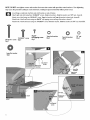
Insert front brace under control panel and between cart side panels. Make sure door hinge pins are on the top side and
facing the front. Secure using two 1/4-20x1Yz" screws, 7ram lock washers, and 7ram flat washers on each side.
7turn Lock washer
Qty.4
7rnrn flat washer
Qty.4
1/4-20x1Y2"
screw
Qty.4
7rnrnflat
washer
7rnrnlock
washer
1/4-20xIVz"
screw
Inside of cart, insert rear tab of tank heat shield into left slot(#1) on top of lower back panel. Insert left grease tray rail into
slot(#2) beneath grease tray opening in upper back panel, shown A. Attach front of tank heat shield and left grease tray rail
brace(#4 and #5) with two #8x3/8" self-tapping screws, shown B. Insert right grease tray rail into slot(#3) and attach it
under front under front brace(#6) with one #8x3/8" self-tapping screws, shown NB.
#8x3/8"self-tappingscrew
Qty.3
...............
Note:somepartsomitted
for clarityof illustration
Greasetrayopening
20
Inserthinge pin on bottomof doorsinto hole in bottom shelf.Press upper hinge pin in front brace, align hinge hole on top of
door,and releasehinge pin into door.
Hingepin
on bottom
of door
I
'II
I1'
I I
I
''
I IIIII1"
III "1'11'11'1"11'1'11'111
I'11111111111111111'11111111111111111'111
Connect eachof the wiresfrom the main burnerelectrodes,and sideburnerelectrode intothe back of the ElectronicIgnition
Module. Total (5) connections.Connectthe two wires{(a)and(b)}from the switchwiring harnessinto the back of the Electronic
Ignition Module. Total (2) connections,shown A.
Releasethe cap and nut from electronicignition module.Attach electronicignitionmoduleto the cart right sidepanel with
the nut, shown B. InsertAA batteryinto ignitionmodule, negative(-) end first. Thenput on the cap, shown C.
NOTE: Switch terminals are larger than electrode terminals and should only be installed in location shown
as (a), (b). Do not untie the wires while attaching.
Nut
Wire
21
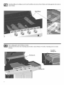
Install heat diffusers by sliding one end of each heat diffuser into slots at front of firebox and resting opposite end on pins at
back of firebox.
Heat diffuser
Place cooking grates onto the firebox as shown.
Insert the two wire ends at rear of warming rack into holes in back of firebox. Front wires of warming rack rest on sides
of firebox.
Assembled
warming rack
rack
ing grate
On back of grill, slide grease tray into opening in upper back panel.
Greasetray
m
m
cAuTioN
Failure to install grease tray wiil
cause hot grease to drip from bottom
of grill with risk of fire or property
damage.
23
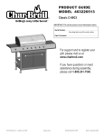
LP CYLINDER IS SOLD SEPARATELY. Fill and leak check the cylinder before attaching to grill and regulator (see Use &
Care section). Once cylinder has been filled and leak checked, place cylinder into hole in bottom shelf. Make sure cylinder
valve is facing front of grill. Secure cylinder with cylinder screw under bottom shelf. Insert regulator through large hole in
left side panel. See Use & Care section of this manual to perform the "Burner
important
safety instructions
Flame Check" and for
before using.
Always keep LP cylinders in upright position during
use, transport, and storage.
Regulator
CAUTION/
Cylinder valve must face to front of cart once
tank is attached. Failure to install cylinder
correctly may allow gas hose to be damaged
in operation, resulting in the risk of fire.
24
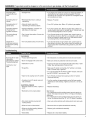
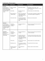
DANGER;
If a gas leak cannot be stopped, or a fire occurs due to gas leakage, call the fire department.
Gasleakingfrom
cracked/cut/burned
hose.
• Damagedhose.
. Turnoff gas at LP cylinderor at sourceon naturalgassystems.If
anythingbut burned,replacevalve/hose/regulator.
If burned,
discontinueuseof productuntila plumberhas investigatedcause
and correctionsare made.
Gasleakingfrom LP
cylinder.
• Mechanicalfailuredue to rustingor
mishandling.
• ReplaceLP cylinder.
Gasleakingfrom LP
cylindervalve.
• Failureof cylindervalve from
mishandlingor mechanicalfailure.
•Turnoff LP cylindervalve.ReturnLP cylinderto gassupplier.
Gasleakingbetween
LP cylinderand
regulatorconnection.
• Improperinstallation,connectionnot
tight,failureof rubberseal.
•Turnoff LP cylindervalve.Removeregulatorfrom cylinderand
visuallyinspectrubbersealfor damage.See LP CylinderLeakTest
and ConnectingRegulatorto the LP Cylinder.
Firecomingthrough
controlpanel.
• Firein burnertube sectionof burnerdue
to blockage.
•Turnoff control knobsand LP cylindervalve.Leavelid opento
allowflamesto die down.After fire is outand grill is cold,remove
burnerand inspectfor spidernestsor rust.See NaturalHazard
and Cleaningthe BurnerAssemblypages.
Greasefire or
continuousexcessive
flamesabovecooking
surface.
•Toomuchgreasebuildupin burnerarea.
•Turnoff control knobsand LP cylindervalve.Leavelid opento
allowflamesto die down.After cooling,cleanfood particlesand
excessgreasefrom insidefireboxarea,greasetray,and other
surfaces.
Troubleshooting
Burner(s)will not light
usingignitor.
(See ElectronicIgnition
Troubleshooting
also)
GASISSUES:
•Tryingto lightwrongburner.
• Seeinstructionson control paneland in Useand Caresection.
• Burnernot engagedwith controlvalve.
• Makesurevalvesare positionedinsideof burnertubes.
• Obstructionin burner.
• Ensureburnertubesare not obstructedwith spiderwebsor other
matter.See cleaningsectionof Useand Care.
. Nogas flow.
• MakesureLP cylinderis not empty.If LP cylinderis notempty,
referto "Suddendrop in gasflow."
Continuedon next
page.
• Fora grill equippedwith theAUTO-CLEAN
TM feature,makesure
theAUTO-CLEAN
TM valve is set to "Grill"
•Vaporlock at couplingnutto LP cylinder.
•Turnoff knobsand disconnectcouplingnut from LPcylinder.
Reconnectand retry.
• Couplingnut and LP cylindervalve not
fully connected.
•Turnthe couplingnutapproximatelyone-halfto three-quarters
additionalturn untilsolidstop.Tightenby handonly- do not use
tools.
ELECTRICALISSUES:
• Electrodecrackedor broken;"sparksat
crack."
• Replaceelectrode(s).
• Electrodetip notin properposition.
MainBurners:
•Tip of electrodeshouldbe pointingtowardgasport openingon
burner.The distanceshouldbe 118"to 114".Adjust if necessary.
Sideburner:
•Tip of electrodeshouldbe pointingtowardgasport openingon
burner,the distanceshouldbe 118"to 3116".Adjust if necessary.
•Wire and/orelectrodecoveredwith
cookingresidue.
• Cleanwireand/orelectrodewith rubbingalcoholand cleanswab.
•Wires are looseor disconnected.
• Reconnectwiresor replaceelectrode/wireassembly.
•Wires are shorting(sparking)between
ignitorand electrode.
• Replaceignitorwire/electrodeassembly.
• Deadbattery.
• Replacewith a newalkalinebattery.
25
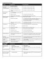
Troubleshooting (continued)
Burner(s)will not light
usingignitor.
(See ElectronicIgnition
Troubleshooting
also)
Burner(s)will not
matchlight.
ELECTRONICIGNITION:
• Nospark,no ignitionnoise.
• SeeSectionI of ElectronicIgnitionSystem.
• Nospark,someignitionnoise.
• SeeSectionII of ElectronicIgnitionSystem.
, Sparks,but notat electrodeor at full
strength.
• SeeSectionIII of ElectronicIgnitionSystem.
• See"GAS ISSUES:"on previouspage.
• Matchwill not reach.
, Uselong-stemmatch(fireplacematch).
• Impropermethodof match-lighting.
• See"Match-Lighting"sectionof Useand Care.
, Outof gas.
• Checkfor gasin LP cylinder.
• Excessflow valvetripped.
•Turnoff knobs,wait 30 secondsand lightgrill. If flamesare still low,
turnoff knobsand LP cylindervalve.Disconnectregulator.
Reconnectregulatorand leak-test.Turnon LP cylindervalve,wait
30 secondsand thenlightgrill.
•Vaporlock at couplingnut/LPcylinder
connection.
•Turnoff knobsand LP cylindervalve.Disconnectcouplingnutfrom
cylinder.Reconnectand retry.
• Highor gustingwinds.
•Turnfront of grill to face windor increaseflameheight.
• Lowon LP gas.
• RefillLP cylinder.
• Excessflow valvetripped.
• Referto "Suddendrop in gasflow"above.
• Greasebuildup.
• Cleanburnersand insideof grilltfirebox.
• Excessivefat in meat.
•Trim fat from meat beforegrilling.
• Excessivecookingtemperature.
•Adjust(lower)temperatureaccordingly.
Persistentgreasefire.
• Greasetrappedby foodbuilduparound
burnersystem.
•Turnknobsto OFF.Turngas off at LPcylinder.Leavelid in position
and let fire burnout.After grill cools,removeandcleanall parts.
Flashback...
(firein burnertube(s)),
• Burnerand/orburnertubesare blocked.
•Turnknobsto OFF.Cleanburnerand/orburnertubes.See burner
cleaningsectionof Use and Care.
Unableto fill LP
cylinder.
• Somedealershaveolder fill nozzles
withworn threads,
•The wornnozzlesdon'thaveenough"bite"to engagethe valve.Try
a secondLPdealer.
One burnerdoes not
lightfrom other
burner(s).
• Greasebuildupor foodparticlesin
end(s)of carryovertube(s).
• Cleancarry-overtube(s)with wirebrush.
Suddendrop in gas
flow or low flame.
Flamesblowout.
Flare-up.
Timerdoesnot work
(Greenlightdoesnot
flash)
•
•
•
DeadBattery
Batteriesinstalledincorrectly.
Knob Positiondid notstart the Clean
Cycle
•
•
•
Replacebatteries
Installbatteriescorrectly.
PushKnobin to startthe cleancycle.(GreenLEDshouldbeginto
flash)
No LED'swill illuminate
•
DeadBattery
•
Replacebatteries
RedLED nextto battery
symbolis illuminated
•
LowBatteryStrength
•
Prepareto replacebatteries(NOTE:Cleancyclewill operatewith
a weak battery.
26
Troubleshooting - Electronic Ignition
SECTIONI
Nosparksappearat
• Batterynot installed
anyelectrodeswhen
properly.
ElectronicIgnitionButton
is pressed;no noise can
be heardfromspark
, Deadbattery.
module.
, Checkbatteryorientation.
• Installbattery(makesurethat "+"and "-"
connectorsare orientedcorrectly,with "+"end up
and "-" enddown.)
, Has batterybeen used
previously?
, Replacebatterywith newalkalinebattery.
, Buttonassemblynot
installedproperly.
Checkto insurethreadsare
properlyengaged.Button
shouldtravelup and down
withoutbinding.
, Unscrewbuttoncap assemblyand reinstall,making
sure threadsare alignedand engagedfully.
, Faultysparkmodule.
If no sparksare generated
with new batteryand good
wire connections,moduleis
faulty.
, Replacespark moduleassembly.
SECTIONII
• Outputlead
Nosparksappearat
connectionsnot
any electrodeswhen
ElectronicIgnitionButton connected.
is pressed;noisecan
be heardfrom spark
module.
, Are outputconnectionson
and tight?
, Removeand reconnectall outputconnectionsat
moduleandelectrodes.
SECTIONill
Sparksare present
butnot at all
electrodesand/ornot
at fullstrength
, Are outputconnectionson
and tight?
, Removeand reconnectall outputconnectionsat
moduleandelectrodes.
• Outputlead
connectionsnot
connected.
, Arcingto grill away
from burner(s).
If possible,observegrill in
dark location.Operate
ignitionsystemand lookfor
arcingbetweenoutputwires
and grill frame.
• If sparksare observedotherthan fromburner(s),
wire insulationmay be damaged.Replacewires.
, Weakbattery.
All sparkspresentbutweak
or at slow rate.
, Replacebatterywith a newalkalinebattery.
, Electrodesare wet.
Has moistureaccumulated
on electrodeand/orin burner
ports?
, Use papertowel to removemoisture.
, Electrodescrackedor
broken"sparksat
crack".
Inspectelectrodesfor
cracks.
, Replacecrackedor brokenelectrodes.
27
28
29
30
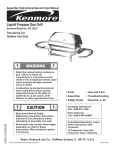
Please register your product online at:
(If you
PLEASE FILL OUTTHIS
register
online,
CARD AND ATTACH A COPY OF YOUR SALES RECEIPT. RETURN IT WITHIN
WILL BE REQUIRED. THIS WARRANTY
you
do not need
to send
in this
registration
card.)
10 DAYS OF PURCHASE. FOR WARRANTY SERVICE PROOF OF PURCHASE
IS NON-TRANSFERABLE.
LLENE ESTA TARJETA Y DEVUELVALA DENTRO DE LOS 10 DIAS DE LA COMPRA. PARA EL SERVlCIO DE GARANTIA ES NECESARIO QUE PRESENTE SU COMPROBANTE
COMPRA. CONSERVE LA FACTURA. ESTA GARANTIA ES INTRANSFERIBLE.
DE
VEUILLEZ COMPLETER CETTE CARTE ET LA RETOURNER DANS LES 10 JOURS SUIVANT L'ACHAT. POUR OBTENIR LE SERVICE SOUS GARANTIE, UNE PREUVE D'ACHAT DOlT
ETRE PRESENTEE. VEUILLEZ CONSERVER VOTRE FACTURE. LA PRESENTE GARANTIE N'EST PAS TRANSFERABLE.
_Required
_O
/ Necesario
~ PLEASE PRINT
/ Exig_
First Name I Nombre
Address
(number
City I Cludad
I Pr_nom
& street)
Initial
I Direcci6n
(n0mero
y calle)
I Adresse
E-mail
Address
I Direcci6n
*
Model
Number
I N6mero
de correo electr6nico
Last Name
Apt Number
et rue)
State I Estado
_O
POR FAVOR ~ S'IL VOUS PLA'[T IMPRIMER
llnicialllnitiale
(num_ro
I Ville
~ IMPRIMA
I Province
I Adresse _lectronique
I Apellido
~
I Nora de Famillie
I N-°de apart
I N-°d'app t.
Zip Code I C6digo Zip I Code Postal
Phone Number
O
I N_mero
telef6nico
I Num_ro
de t_l_phone
RGAS_
de modelo
I Numero
de model
_,_
A
Serial Number
O
I N_mero de seriel
Date of Purchase
Num_ro
I Fecha de compra
Attach
ST_CKERON PRODUCT
de s_rie
sales receipt
I Date de I'achat
O
Store Name
I Nombre
O
Your Gender
de la tienda
I Nora du magasin
S
0
I Prix d'achat
[]Malel
Adjunte aquila copia
de su recibo de
I Sexo I Sexe:
Masculinol
[]Female
Which
here.
compra
Purchase Price I Precio de compra
0
copy of your
I Femeninol
Veuillez
Masculin
F_minin
attacher
une
copie de votre regu
ici.
product are you registering?
_,Qu_ producto est_ registrando?
Quel produit enregistrez-vous?
i.
[_Gas
2.
[_ Electric
3.
4.
[_Smoker
I Ahumador
I Fumoir
[_ Charcoal Grill I Parrilla a carb6n
5.
[_ Cooker/Fryer
I Cocina/freidora
6.
[]Otherl
I Autre
Envielo
Grill l Parrilla a gas I Gril au gaz
Grill ] Parrilla el_ctrica
Otro
We respect your privacy.
®
If you prefer
•
Marque
®
Si vous pr6f6rez
] Gril _lectrique
I Barbecue
[ Respetamos
Columbus, GA 31902-1240
su privacidad.
not to receive special offers and promotions
ne pas recevoir
de Charbroil,
Thank you for completing
veuillez
ofertas
y promociones
d'informations
Registration
P.O. Box 1240
au charbon
I Cuiseur/Friteuse
aqu[ si no desea recibir
promotions
Char-Broil Warranty
a:
[ Nous respectons votre vie priv_e.
from Char-Broil,
especiales
concernant
please check here:
[
_
de Char-Broil:
des offres sp_ciales et des
cocher ici:
this questionnaire.
[ Gracias
par completer
este cuestionario.
I Merci d'avoir
bien voulu
remplir
ce questionnaire.
31
Register your product to receive a special offer
www.c h a rb roi i.co m/reg iste r
iiiiiiiiiiiiiiiiiiiii