1
Instruction Manual
Modero X-Series
G4 Touch Panels
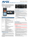
MXT/D-2000-PAN - 20.3" Modero X Series Panoramic Touch Panels
MXT/D-1900-PAN - 19.4" Modero X Series Panoramic Touch Panels
MXT/D-1000-PAN - 10.1" Modero X Series Touch Panels
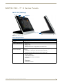
MXT/D-701-PAN - 7" Modero X Series Touch Panels
MXD-430 - 4.3" Modero X Series Wall Mount Touch Panel
Modero X Series G4 Touch Panels
L a s t R e v is e d : 9 / 1 9 / 2 0 1 4
AMX Limited Warranty and Disclaimer
This Limited Warranty and Disclaimer extends only to products purchased directly from AMX or an AMX Authorized Partner which
include AMX Dealers, Distributors, VIP’s or other AMX authorized entity.
AMX warrants its products to be free of defects in material and workmanship under normal use for three (3) years from the date of
purchase, with the following exceptions:
•
Electroluminescent and LCD Control Panels are warranted for three (3) years, except for the display and touch overlay components are warranted for a period of one (1) year.
•
Disk drive mechanisms, pan/tilt heads, power supplies, and MX Series products are warranted for a period of one (1) year.
•
AMX lighting products are guaranteed to switch on and off any load that is properly connected to our lighting products, as long
as the AMX lighting products are under warranty. AMX also guarantees the control of dimmable loads that are properly connected to our lighting products. The dimming performance or quality there of is not guaranteed, impart due to the random combinations of dimmers, lamps and ballasts or transformers.
•
AMX software is warranted for a period of ninety (90) days.
•
Batteries and incandescent lamps are not covered under the warranty.
•
AMX AutoPatch Epica, Modula, Modula Series4, Modula CatPro Series and 8Y-3000 product models will be free of defects in
materials and manufacture at the time of sale and will remain in good working order for a period of three (3) years following the
date of the original sales invoice from AMX. The three-year warranty period will be extended to the life of the product (Limited
Lifetime Warranty) if the warranty card is filled out by the dealer and/or end user and returned to AMX so that AMX receives it
within thirty (30) days of the installation of equipment but no later than six (6) months from original AMX sales invoice date. The
life of the product extends until five (5) years after AMX ceases manufacturing the product model. The Limited Lifetime Warranty
applies to products in their original installation only. If a product is moved to a different installation, the Limited Lifetime Warranty
will no longer apply, and the product warranty will instead be the three (3) year Limited Warranty.
All products returned to AMX require a Return Material Authorization (RMA) number. The RMA number is obtained from the AMX
RMA Department. The RMA number must be clearly marked on the outside of each box. The RMA is valid for a 30-day period. After
the 30-day period the RMA will be cancelled. Any shipments received not consistent with the RMA, or after the RMA is cancelled, will
be refused. AMX is not responsible for products returned without a valid RMA number.
AMX is not liable for any damages caused by its products or for the failure of its products to perform. This includes any lost profits, lost
savings, incidental damages, or consequential damages. AMX is not liable for any claim made by a third party or by an AMX Authorized Partner for a third party.
This Limited Warranty does not apply to (a) any AMX product that has been modified, altered or repaired by an unauthorized agent or
improperly transported, stored, installed, used, or maintained; (b) damage caused by acts of nature, including flood, erosion, or earthquake; (c) damage caused by a sustained low or high voltage situation or by a low or high voltage disturbance, including brownouts,
sags, spikes, or power outages; or (d) damage caused by war, vandalism, theft, depletion, or obsolescence.
This limitation of liability applies whether damages are sought, or a claim is made, under this warranty or as a tort claim (including
negligence and strict product liability), a contract claim, or any other claim. This limitation of liability cannot be waived or amended by
any person. This limitation of liability will be effective even if AMX or an authorized representative of AMX has been advised of the
possibility of any such damages. This limitation of liability, however, will not apply to claims for personal injury.
Some states do not allow a limitation of how long an implied warranty last. Some states do not allow the limitation or exclusion of incidental or consequential damages for consumer products. In such states, the limitation or exclusion of the Limited Warranty may not
apply. This Limited Warranty gives the owner specific legal rights. The owner may also have other rights that vary from state to state.
The owner is advised to consult applicable state laws for full determination of rights.
EXCEPT AS EXPRESSLY SET FORTH IN THIS WARRANTY, AMX MAKES NO OTHER WARRANTIES, EXPRESSED OR
IMPLIED, INCLUDING ANY IMPLIED WARRANTIES OF MERCHANTABILITY OR FITNESS FOR A PARTICULAR PURPOSE. AMX
EXPRESSLY DISCLAIMS ALL WARRANTIES NOT STATED IN THIS LIMITED WARRANTY. ANY IMPLIED WARRANTIES THAT
MAY BE IMPOSED BY LAW ARE LIMITED TO THE TERMS OF THIS LIMITED WARRANTY. EXCEPT AS OTHERWISE LIMITED
BY APPLICABLE LAW, AMX RESERVES THE RIGHT TO MODIFY OR DISCONTINUE DESIGNS, SPECIFICATIONS, WARRANTIES, PRICES, AND POLICIES WITHOUT NOTICE.
Table of Contents
Table of Contents
Modero X Series G4 Touch Panels ......................................................................1
Overview .................................................................................................................. 1
Sleep Button ............................................................................................................. 2
Configuration and Programming .............................................................................. 2
Accessing the Settings Menu .......................................................................................... 3
Using the Settings Pages................................................................................................. 3
Bluetooth Support .................................................................................................... 3
NFC Support............................................................................................................. 3
Active Video Windows - Limitations.......................................................................... 4
Picture View.............................................................................................................. 4
Starting Picture View....................................................................................................... 4
Preview Mode and Normal Mode ................................................................................... 5
Picture View Send Command (^PIC)................................................................................ 5
Cleaning the Touch Overlay and Case ...................................................................... 6
MXT/D-2000XL-PAN - 20.3" X Series Panels ......................................................7
MXT-2000XL-PAN (Tabletop).................................................................................... 7
MXT-2000XL-PAN Specifications .................................................................................... 7
MXD-2000XL-PAN (Wall Mount-Landscape/Portrait).............................................. 10
MXD-2000XL-PAN Specifications ................................................................................. 10
MXT/D-1900L-PAN - 19.4" X Series Panels ......................................................15
MXT-1900L-PAN (Tabletop). ................................................................................... 15
MXT-1900L-PAN Specifications .................................................................................... 15
MXD-1900L-PAN (Wall Mount-Landscape/Portrait) ................................................ 18
MXD-1900L-PAN Specifications ................................................................................... 18
MXT/D-1000 - 10.1" X Series Panels ................................................................23
MXT-1000 (Tabletop) .............................................................................................. 23
MXT-1000 Specifications ............................................................................................... 23
Touch Panel Aspect Ratio ......................................................................................................... 25
MXD-1000 (Wall-Mount - Landscape/Portrait) ........................................................ 26
MXD-1000 Specifications .............................................................................................. 26
Touch Panel Aspect Ratio ......................................................................................................... 29
MXT/D-700 - 7" X Series Panels .......................................................................31
MXT-700 (Tabletop) ............................................................................................... 31
MXT-700 Specifications ................................................................................................ 31
Touch Panel Aspect Ratio ......................................................................................................... 33
MXD-700 (Wall-Mount - Landscape/Portrait) .......................................................... 34
MXD-700 Specifications ................................................................................................ 34
Touch Panel Aspect Ratio ......................................................................................................... 36
Modero X® Series G4 Touch Panels Instruction Manual
i
Table of Contents
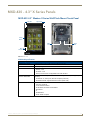
MXD-430 - 4.3” X Series Panels .......................................................................37
MXD-430 4.3" Modero X Series Wall/Flush Mount Touch Panel ........................... 37
MXD-430 Specifications ................................................................................................ 37
Installing Tabletop (MXT) Panels ......................................................................41
MXT-2000XL-PAN / MXT-1900L-PAN ..................................................................... 41
Connector Locations - MXT-2000XL-PAN / MXT-1900L-PAN ........................................ 41
MXT-1000 / MXT-700 ............................................................................................. 42
Connector Locations - MXT-1000/MXT-700 .................................................................. 42
Power via 12 VDC ......................................................................................................... 42
Wiring a 12VDC Power Connection .......................................................................................... 42
Power via PoE ............................................................................................................... 43
Ethernet Cable Installation and Modification............................................................................ 43
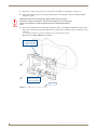
Installing Wall-Mount (MXD) Panels ..................................................................45
A Note About Wall and Rack Installation................................................................ 45
Installation Recommendations....................................................................................... 46
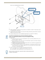
MXD-2000XL-PAN / MXD-1900L-PAN Installation.................................................. 46
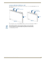
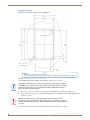
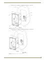
Installing the MXD-2000XL-PAN / MXD-1900L-PAN Into a Wall ................................... 47
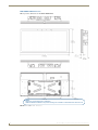
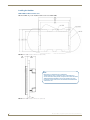
MXD-2000XL-PAN Dimensions ................................................................................................. 48
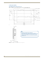
MXD-1900L-PAN Dimensions ................................................................................................... 49
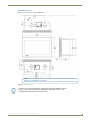
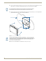
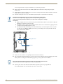
Installing the Backbox ................................................................................................... 50
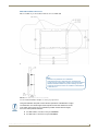
MXD-2000XL-PAN Installation Dimensions............................................................................... 50
MXD-1900L-PAN Installation Dimensions ................................................................................. 51
Power via 12 VDC ......................................................................................................... 54
Wiring a 12VDC Power Connection .......................................................................................... 55
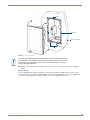
Uninstalling the MXD-2000XL-PAN / MXT-1900L-PAN ................................................. 55
Removing the Panel From Its Backbox...................................................................................... 55
MXD-1000/ MXD-700 Installation ........................................................................... 56
Installing the MXD-1000 / MXD-700 Into a Wall ........................................................... 57
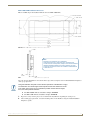
MXD-1000 Dimensions ............................................................................................................. 58
MXD-700 Dimensions ............................................................................................................... 59
Installing the Backbox ................................................................................................... 60
MXD-1000 Installation Dimensions ........................................................................................... 60
MXD-700 Installation Dimensions ............................................................................................. 61
Power via PoE ............................................................................................................... 65
Ethernet Cable Installation and Modification............................................................................ 65
Uninstalling the MXD-1000 ........................................................................................... 66
Removing the MXD-1000 From Its Backbox ............................................................................. 66
Uninstalling the MXD-700 ............................................................................................. 67
Removing the MXD-700 From Its Backbox ............................................................................... 67
MXD-430 Installation .............................................................................................. 68
Installing the MXD-430 Into a Wall ........................................................................................... 69
Installing the Backbox............................................................................................................... 70
Power via PoE ............................................................................................................... 73
ii
Modero X® Series G4 Touch Panels Instruction Manual
Table of Contents
Uninstalling the MXD-430 ............................................................................................. 74
Removing an MXD-430 from Its Backbox ................................................................................. 74
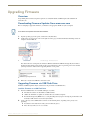
Upgrading Firmware .........................................................................................75
Overview ................................................................................................................ 75
Downloading Firmware Updates From www.amx.com ........................................... 75
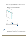
Upgrading Firmware via USB Flash Drive ............................................................... 75
Load the Firmware on a USB Flash Drive ...................................................................... 75
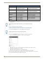
Transfer the Firmware File From the Flash Drive to the Touch Panel............................ 76
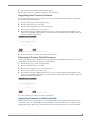
Upgrading from Previous Firmware ........................................................................ 77
Returning to Factory Default Firmware .................................................................. 77
Upgrading Firmware via NetLinx Studio................................................................. 77
Transferring the KIT File via NetLinx Studio.................................................................. 78
Troubleshooting ...............................................................................................79
Overview ................................................................................................................ 79
Panel Doesn’t Respond To Touches .............................................................................. 79
Panel Isn’t Appearing In The Online Tree Tab ............................................................... 79
Can’t Connect To a NetLinx Master .............................................................................. 79
Only One Modero X Series Panel In My System Shows Up ........................................... 79
Modero X® Series G4 Touch Panels Instruction Manual
iii
Table of Contents
iv
Modero X® Series G4 Touch Panels Instruction Manual
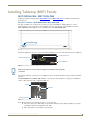
Modero X Series G4 Touch Panels
Modero X Series G4 Touch Panels
Overview
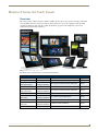
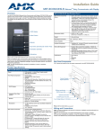
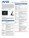
This new generation of G4 touch panels is built for usability offering edge-to-edge capacitive touch glass with multitouch capabilities. It features advanced technology empowering users to operate AV equipment seamlessly, while
providing the ultimate in audio and video quality. The distinctive appearance will complement even the most
sophisticated meeting facilities and homes.
FIG. 1 Modero X Series G4 Touch Panels
The Modero X Series Touch Panels covered in this manual include:
Modero X Series Touch Panels
Name
FG#
Description
Page Ref
MXT-2000XL-PAN
FG5968-01
20.3" Modero X Series Panoramic Tabletop
page 7
MXD-2000XL-PAN-P
Portrait: FG5968-05
MXD-2000XL-PAN-L
Landscape: FG5968-11
20.3" Modero X Series Panoramic Wall Mounts
page 10
MXT-1900L-PAN
FG5968-02
19.4" Modero X Series Panoramic Tabletop
page 15
MXD-1900L-PAN-P
Portrait: FG5968-06
MXD-1900L-PAN-L
Landscape: FG5968-12
19.4" Modero X Series Panoramic Wall Mounts
page 18
MXT-1000
FG5968-03
10.1" Modero X Series Tabletop
page 23
MXD-1000-P
MXD-1000-L
Portrait: FG5968-07
Landscape: FG5968-13
10.1" Modero X Series Wall-Mounts
page 26
MXT-700
FG5968-04
7" Modero X Series Tabletop
page 31
MXD-700-P
Portrait: FG5968-08
MXD-700-L
Landscape: FG5968-14
7" Modero X Series Wall-Mount
page 34
MXD-430
FG5968-15
4.3" Modero X Series Wall/Flush Mount
page 37
Modero X® Series G4 Touch Panels Instruction Manual
1
Modero X Series G4 Touch Panels
Modero X Series Touch Panels (Cont.)
Name
FG#
Description
X Series - No Comm Panels:
The X Series - No Comm Panels do not have camera, microphone, NFC or Bluetooth capability. Otherwise, they
have all of the functionality of the standard Modero X Series panels.
MXT-2000XL-PAN-NC
FG5968-32
MXD-2000XL-PAN-P-NC
Portrait: FG5968-33
MXD-2000XL-PAN-L-NC
Landscape: FG5968-34
MXT-1900L-PAN-NC
FG5968-21
MXD-1900L-PAN-P-NC
Portrait: FG5968-22
MXD-1900L-PAN-L-NC
Landscape: FG5968-23
MXT-1000-NC
FG5968-24
MXD-1000-P-NC
Portrait: FG5968-25
MXD-1000-L-NC
Landscape: FG5968-26
MXT-700-NC
FG5968-27
MXD-700-P-NC
Portrait: FG5968-28
MXD-700-L-NC
Landscape: FG5968-29
No Comm 20.3" Modero X Series Panoramic Tabletop
No Comm 20.3" Modero X Series Panoramic Wall Mounts
No Comm 19.4" Modero X Series Panoramic Tabletop
No Comm 19.4" Modero X Series Panoramic Wall Mounts
No Comm 10.1" Modero X Series Tabletop
No Comm 10.1" Modero X Series Wall Mounts
No Comm 7" Modero X Series Tabletop
No Comm 7" Modero X Series Wall-Mounts
The X Series panels described in this document represent a different product family
than the X Series G5 touch panels. For information on X Series G5 touch panels,
refer to the Modero X Series G5 Touch Panels Instruction Manual.
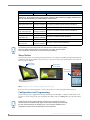
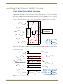
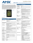
Sleep Button
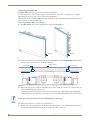
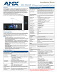
X Series touch panels are operated using an integral touchscreen, as well as the Sleep button. For tabletop and landscape
wall-mount panels, the Sleep button is located on the top center edge of the panel; for portrait panels it is located at the
left center edge.(see FIG. 2).
Sleep button
(on top panel)
Sleep button
(on top panel)
Sleep button
(on left panel)
FIG. 2 Sleep Button location - Tabletop, Landscape and Portrait layouts)
If the device has gone into its Sleep Mode, a touch of the touchscreen or of the Sleep button will reactivate it.
Configuration and Programming
X Series touch panels are equipped with a Settings menu that provides the ability to configure various features on the
panels. To access the Settings menu, press and hold the Sleep button, and select Settings. This opens the main Settings
menu
Unlike previous G4 touch panels, Modero X Series G4 touch panels do not have
separate Setup and Protected Setup pages. All touch panel settings and functionality
are now controlled through one Settings menu. The Connection & Networks and
Configuration sections are accessible with the correct password.
2
Modero X® Series G4 Touch Panels Instruction Manual
Modero X Series G4 Touch Panels
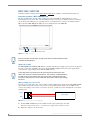
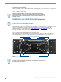
Accessing the Settings Menu
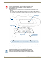
1. To access the Settings menu, press and hold the Sleep button on the touch panel for 3 seconds.
Alternately, some installation circumstances may require disabling Settings page access through the Sleep
button. In this case, you may access Settings pages during a bootup of the panel.
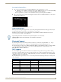
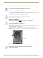
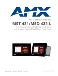
As the panel boots up, watch for a series of indicator dots to appear on the splash screen (FIG. 3).
2. To access the Settings menu, press the bottom right corner of the touchscreen within the first three seconds of these
dots appearing on the screen.
FIG. 3 Indicator dots on the Modero X Series splash screen
Using the Settings Pages
When opened, the Settings menu appears in the center of the panel display. Note that many of the pages may be longer
than they initially appear. Scroll down to reach all functions on a given page.
Information on the Settings menu, panel configuration, and programming is included in the Modero X Series G4
Programming Guide, available at www.amx.com.
Programming the Modero X Series G4 touch panels require the use of the latest
versions of NetLinx Studio and TPDesign4, both available to download at
www.amx.com.
Bluetooth Support
X Series G4 panels allow the use of Bluetooth keyboard and mouse combinations, using HID Profile v1.1. Using a
keyboard and mouse with the device requires use of the MXA-BT Bluetooth USB Adapter (FG5968-19).
X Series G4 panels also allow the use of Bluetooth Hands Free Handset, using Hands Free Profile v1.5, Headset Profile
v1.2. Using a Hands Free Handset with the device requires the MXA-BT Bluetooth Adapter (FG5968-19) and
MXA-HST Bluetooth Handset (FG5968-17)
NFC Support
X Series G4 panels support Near Field Communications™ (NFC) Technology. NFC technology facilitates making
transactions, exchanging digital content, and connecting electronic devices with a touch. NFC transmissions are shortrange (from a touch to a few centimeters), working with existing contact-less card technologies and containing built-in
capabilities to support secure applications.
By using NFC technology, users may receive access to touch panels and touch panel pages through access badges and
other card options.
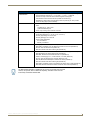
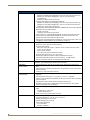
Common Access Card (CAC) Support In MXT/D-2000XL-PAN
Card Type
Card Unique Identifier (UID) Card Data
Personal Identity Verification (PIV) Card
holder UID
15693
8 byte UID
Not Supported
N/A
Not Supported
N/A
14443A Non-Gov't 4, 7 or 10 byte UID (1)
14443A Gov't
4, 7 or 10 byte UID (1)
Not Supported (2) Not currently
14443B Non-Gov't 4 byte UID
Not Supported
N/A
14443B Gov't
4 byte UID
Not Supported (2) Not currently
FeliCa
Not Supported
Not Supported
N/A
(1) The UID can be a fixed unique number or a random number dynamically generated by the card.
(2) Requires contact card reader (not accessible via NFC)
Modero X® Series G4 Touch Panels Instruction Manual
3
Modero X Series G4 Touch Panels
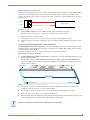
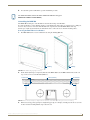
The maximum range for the NFC antenna is 0.5" (12.7 mm), but the typical usage range is 0.25" (6.35 mm).
The antenna itself is accessible from the front of the panel, 3.25" (82.55 mm) from the left corner of the panel
and 0.375" (9.53 mm) from the top edge.
When using an NFC device with the X Series panels, you should align your device’s antenna with the center of the touch
panel’s antenna (FIG. 4).
NFC Sensor
NFC Sensor
NFC Sensor
FIG. 4 NFC antenna location (Tabletop, Landscape and Portrait layouts)
To facilitate NFC antenna access, consider adding an icon to the panel’s page(s),
pointing to the location of the antenna on the panel.
Active Video Windows - Limitations
The following limitations apply to the display of active video windows on X Series panels:
The term "Active Video Windows" refers to any "window" on the touch panel (which
could be a Page, Popup, Sub-Page or Button) that is displaying active video content.
Maximum supported number of active video windows displayed simultaneously on the panel: 2
While this limitation is not enforced (i.e the TPDesign5 application will allow you include any number of
video windows in the panel design), attempting to display more than two active video windows at one time
may have a negative impact on the panel’s overall performance.
Maximum supported resolution for video windows: 720dpi
Maximum supported frame rate for video windows: 30fps
Picture View
By connecting a USB drive via one of the device’s USB ports, Picture View allows the Modero X Series panel to access
JPEG images on that drive and display them on the touchscreen. Individual images may be accessed at any time, or the
entire collection may be displayed for predetermined times. Picture View may be stopped at any time by removing the
USB drive, and the panel will return to its default display page.
The maximum source resolution for Picture View is 1920x1920 pixels.The maximum
displayed resolution is the same as the screen resolution.
Starting Picture View
1. Connect a USB drive to the device. Picture View will automatically recognize all available images on the drive and
start displaying them on the touchscreen.
4
Modero X® Series G4 Touch Panels Instruction Manual
Modero X Series G4 Touch Panels
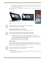
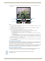
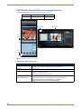
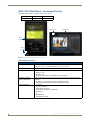
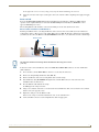
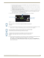
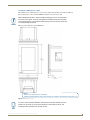
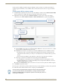
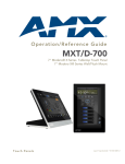
2. When the images begin to display, touch any place on the touchscreen to open the configuration popup menu
(FIG. 5).
Stop
Random / A-Z
Pause/Resume
Timer
Previous image
Next image
Counter
FIG. 5 Picture View Configuration Popup Menu
If no selection is made, this menu will remain in place for 15 seconds and then disappear. It may be accessed again
by touching anywhere on the touchscreen.
3. On the leftmost amber button, select between Rand (images display at random) and A-Z (images display in
alphabetical order based on the name of the file).
4. The four gray buttons allow scrolling through saved images and the rate of display:
The Previous Image Saved button returns the display to the first image uploaded by Page View.
The Stop button stops Page View and returns to the default panel page.
The Pause/Resume button allows the display to stop on one particular image. Press it again to resume the
display procession.
The Next Image Saved button returns the display to the last image uploaded by Page View. If the panel has
not accessed all of the images available on a USB drive, Page View will display the last one uploaded to date.
5. On the rightmost red button, select the number of seconds a selected image will be displayed in Picture View. This
may be selected between 5, 10, 15, 30, and 60 seconds.
6. The counter beneath the buttons displays the number of images currently uploaded by the panel, versus the number
detected on the USB drive.
Preview Mode and Normal Mode
Picture View has two modes: Preview Mode and Normal Mode. Preview Mode allows the user to configure Picture View.
Once a USB drive containing images is inserted into the panel, the images will begin to display. Touching any place on
the display will result in the configuration popup to slide from the bottom of the display.
Picture View goes into its Normal Mode when the panel goes into idle timeout while connected to a USB drive. Normal
Mode displays images until the touchscreen is touched, or some other wakeup event is detected. When the device goes
back into timeout, Normal Mode will return to displaying images until the USB drive is removed from the device.
Picture View Send Command (^PIC)
The ^PIC Send Command stops either mode of Picture View, or starts Preview Mode. For more information, please
refer to the Modero X/S Series G4 Touch Panels Programming Guide, available at www.amx.com.
All images must be in JPEG format. PNG and other image formats cannot be viewed
through Picture View.
Modero X® Series G4 Touch Panels Instruction Manual
5
Modero X Series G4 Touch Panels
Cleaning the Touch Overlay and Case
Modero X Series touch panels come with the MXA-CLK Modero X Series Cleaning Kit (FG5968-16), which may be
used to clean fingerprints and dirt from the device. This kit comes with cleaning cloths and a bottle of cleaning fluid
specifically for use with the device.
When cleaning the device, do not directly spray the device with cleaning fluid. Instead, spray the cloth and
then apply the cloth to the touch screen.
Do not use abrasives of any type to clean the device, as abrasives may permanently damage or remove the
device’s finish.
6
Modero X® Series G4 Touch Panels Instruction Manual
MXT/D-2000XL-PAN - 20.3" X Series Panels
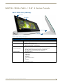
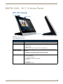
MXT/D-2000XL-PAN - 20.3" X Series Panels
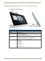
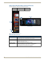
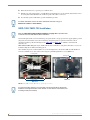
MXT-2000XL-PAN (Tabletop)
NFC Sensor
Sleep Button
USB Ports (2)
Cable Slot
FIG. 6 MXT-2000XL-PAN - Front View
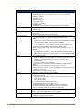
MXT-2000XL-PAN Specifications
MXT-2000XL-PAN Specifications
DIMENSIONS (HWD)
9 3/16" x 20 3/8" x 5 7/8" (235 mm x 519 mm x 150 mm)
WEIGHT
12.2 lbs (5.53 Kg)
POWER CONSUMPTION
• Full-On: 32W (12 VDC, 2.7 A)
• Standby: 3.10 W (12 VDC, 0.3 A)
• Start-Up Inrush Current: 4.0 A for 80 µsec
EXTERNAL POWER
SUPPLY REQUIRED
Requires one of these AMX power sources (not included):
CERTIFICATIONS
•
•
•
•
•
•
•
•
•
• PSN4.4 Power Supply, 4.4 A, 3.5 mm Phoenix, 13.5 VDC (FG423-45)
• MXA-MPL Modero X/S Series Multi Preview Live (FG5968-10)
• MXA-MP Modero X/S Series Multi Preview (FG5968-20)
FCC Part 15 Class B
CE EN 55022
CE EN 55024
CE EN 60950-1
IEC 60950-1
C-Tick CISPR 22 Class B
IC
UL 60950-1
RoHS/WEEE compliant
Modero X® Series G4 Touch Panels Instruction Manual
7
MXT/D-2000XL-PAN - 20.3" X Series Panels
MXT-2000XL-PAN Specifications (Cont.)
TOUCH SCREEN DISPLAY
•
•
•
•
•
•
•
•
•
•
Display Type: TFT Active Matrix Color LCD with In-plane Switching Technology (IPS)
Display Size (WH): 20.4" x 9.5" (519 mm x 242 mm), 21.3" (541 mm) diagonal
Viewable Area (WH): 18.7" x 7.8" (475 mm x 198 mm ), 20.3" (514 mm) diagonal
Resolution: 1920x800
Aspect Ratio: 12:5
Brightness: 250 cd/m2
Contrast Ratio: 1000:1
Color Depth: 16.7M colors
Illumination: LED
Touch Overlay: Projected capacitive, multi-touch support, 3 simultaneous max
VIEWING ANGLE
• Vertical: ± 89°
• Horizontal: ± 89°
MEMORY
• SDRAM: 512 MB
• Flash: 4 GB
• Maximum Project Size: 2.4 GB flash available to user
COMMUNICATIONS
• Ethernet: 10/100 port, RJ-45 connector. Supported IP and IP-based protocols: UCP,
TCP, ICMP, ICSP, IGMP, DHCP, Telnet, FTP, DNS, RFB (for VNC), HTTP
• USB:
(3) USB host 2.0, Type A ports: Firmware upgrade, touch panel file transfer, JPEG
image viewer, HID peripherals, USB audio output for headsets
(1) Micro-USB device port: video output from on-board camera, USB audio from
on-board microphone to host device
• Near Field Communication (NFC): Supports standards ISO/IEC 15693,
ISO/IEC 14443A, ISO/IEC 14443B; Unique Identifier (UID), typ range=.25", max = .5"
• Bluetooth:
Mouse/Keyboard: HID Profile v1.1, requires MXA-BT Bluetooth Adapter (FG5968-19)
Handset: Hands Free Profile v1.5, Headset Profile v1.2, requires MXA-BT Bluetooth
Adapter (FG5968-19) and MXA-HST Bluetooth Handset (FG5968-17)
VIDEO
• Supported Video Codecs:
MPEG2-TS: MPEG-2 Main Profile @High Level up to 720p at 25 fps (decode only)
MPEG-2-TS: H.264 High Profile @Layer 4, AAC-LC up to 720p at 25 fps
(encode/decode)
MJPEG up to 720p at 25 fps (decode only)
• Supported Video Transport Streams: MPEG-TS for MPEG-2 and H.264, HTTP for
MJPEG
• Max Number of Active Video Streams: One decode plus one encode
• Video Output: Camera video output: H.264, up to 720p@25 fps via Micro-USB port only
(controlled by host device)
• Video Conferencing: Panel-to-panel and video chat
AUDIO
• Microphone: -42 dB ±3 dB sensitivity FET microphone
• Speakers: 4 ohm, 2 Watt, 300 Hz cutoff frequency
• Supported Audio Codecs:
MP2 Layer I and II, MP3 (8 kHz, 11.025 kHz, 12 kHz, 16 kHz, 22.05 kHz, 24 kHz,
32 kHz, 44.1 kHz, 48 kHz)
AAC-LC (8 kHz, 96 kHz)
G.711 with µLaw (VoIP encode/decode at 8 kHz)
Suggested max packet size for G.711 Voice: 20ms
• Audio Output: USB Audio out Micro-USB port (controlled by host device)
• File Formats: WAV, MP3 (as part of touch panel file only - no USB storage)
• Intercom: Full Duplex VoIP, SIP v2.0 (supported with AMX-CSG)
8
GRAPHICS ENGINE
AMX G4: G4 enhanced feature set supporting multi-touch and gestures, scrolling,
transitions - See TPD4 Operations Guide for more information
EMBEDDED
APPLICATIONS
• Remote Management: VNC Server, G4 Web Control, AMX Resource Management Suite
• Video Conferencing: Panel-to-panel and video chat
• Conferencing: Audio (Full Duplex Intercom)
Modero X® Series G4 Touch Panels Instruction Manual
MXT/D-2000XL-PAN - 20.3" X Series Panels
MXT-2000XL-PAN Specifications (Cont.)
FRONT PANEL
COMPONENTS
•
•
•
•
•
Light Sensor: Photosensitive light detector for automatic adjustment of the panel brightness
Proximity Detector: Max range = ~3', typ range = ~1', FOV = ~10 degrees
Camera: HD 720p camera for video conferencing/video chat support
LED Indicators: Camera active indicator (models with camera only)
Sleep Button: Sleep button to activate sleep mode and powering off. Also provides
access to setup pages (can be disabled)
CONNECTIONS
• Ethernet: 10/100 port, RJ-45 connector
• USB:
(3) USB host 2.0, Type A ports
(1) Micro-USB device port
• Power: 2-pin, locking 3.5mm Phoenix connector
ENVIRONMENTAL
•
•
•
•
•
Temperature (Operating): 32° F to 104° F (0° C to 40° C)
Temperature (Storage): 4° F to 140° F (-20° C to 60° C)
Humidity (Operating): 20% to 85% RH
Humidity (Storage): 5% to 85% RH
Power ("Heat") Dissipation:
On: 109.2 BTU/hr
Standby: 10.6 BTU/hr
INCLUDED ACCESSORIES •
•
•
•
Locking 2-pin Phoenix mate (41-0002-SA)
MXA-USB-C, USB Port Cover Kit, Modero X/S Series Touch Panel (FG5968-18)
HPG-10-10K, 3/4" Mini-Grommet (FG570-01)
MXA-CLK, Modero X/S Series Cleaning Kit (FG5968-16)
OPTIONAL ACCESSORIES •
•
•
•
•
•
•
•
•
MXA-STMK-20, Secure Table Mount Kit, 20.3" Modero X Tabletop (FG5968-64)
MXA-MP, Modero X/S Series Multi Preview (FG5968-20)
MXA-MPL, Modero X/S Series Multi Preview Live (FG5968-10)
PSN4.4, Power Supply, 4.4 A, 3.5 mm Phoenix, 13.5 VDC (FG423-45)
HPG-10-10K, 3/4" Mini-Grommet, 10-Pack (FG570-01-10K)
MXA-BT, Bluetooth USB Adapter for Modero X/S Series (FG5968-19)
MXA-CLK, Modero X/S Series Cleaning Kit (FG5968-16)
MXA-USB-C, USB Port Covers for the Modero X/S Series Touch Panels (FG5968-18)
MXA-HST, Bluetooth Handset for Modero X/S Series Touch Panels (FG5968-17)
The MXT-2000XL-PAN-NC (FG5968-32) "No Comm" touch panel does not have
camera, microphone, NFC or Bluetooth capability; otherwise it has all of the
functionality of the MXT-2000XL-PAN.
Modero X® Series G4 Touch Panels Instruction Manual
9
MXT/D-2000XL-PAN - 20.3" X Series Panels
MXD-2000XL-PAN (Wall Mount-Landscape/Portrait)
The MXD-2000XL-PAN is available in Portrait and Landscape layouts:.
Portrait
MXD-2000XL-PAN-P
FG5968-05
Landscape
MXD-2000XL-PAN-L
FG5968-11
NFC Sensor
Sleep Button
Sleep
Button
MXD-2000XL-PAN-L
NFC
Sensor
MXD-2000XL-PAN-P
FIG. 7 MXD-2000XL-PAN, Landscape Wall Mount
MXD-2000XL-PAN Specifications
MXD-2000XL-PAN Specifications
10
DIMENSIONS (HWD)
• Landscape: 9 1/2" x 20 3/8" x 11/16" (242 mm x 519 mm x 19 mm)
• Portrait: 20 3/8" x 9 1/2" x 11/16" (519 mm x 242 mm x 19 mm)
WEIGHT
9.1 lbs (4.13 Kg)
POWER CONSUMPTION
• Full-On: 32W (12 VDC, 2.7 A)
• Standby: 3.10 W (12 VDC, 0.3 A)
• Start-Up Inrush Current: 4.0 A for 80 µsec
EXTERNAL POWER
SUPPLY REQUIRED
Requires one of these AMX power sources (not included):
• PSN4.4 Power Supply, 4.4 A, 3.5 mm Phoenix, 13.5 VDC (FG423-45)
• MXA-MPL Modero X/S Series Multi Preview Live (FG5968-10)
• MXA-MP Modero X/S Series Multi Preview (FG5968-20)
Modero X® Series G4 Touch Panels Instruction Manual
MXT/D-2000XL-PAN - 20.3" X Series Panels
MXD-2000XL-PAN Specifications (Cont.)
CERTIFICATIONS
•
•
•
•
•
•
•
•
•
FCC Part 15 Class B
CE EN 55022
CE EN 55024
CE EN 60950-1
IEC 60950-1
C-Tick CISPR 22 Class B
IC
UL 60950-1
RoHS/WEEE compliant
TOUCH SCREEN DISPLAY
• Display Type: TFT Active Matrix Color LCD with In-plane Switching Technology (IPS)
• Display Size (WH)
Landscape: 20.4" x 9.5" (519 mm x 242 mm), 21.3" (541 mm) diagonal
Portrait: 9.5" x 20.4" (242 mm x 519 mm), 21.3" (541 mm) diagonal
• Viewable Area (WH)
Landscape 18.7" x 7.8" (475 mm x 198 mm ), 20.3" (514 mm) diagonal
Portrait 7.8" x 18.7" (198 mm x 475 mm), 20.3" (514 mm) diagonal
• Resolution
Landscape: 1920x800
Portrait: 800x1920
• Aspect Ratio
Landscape: 12:5
Portrait: 5:12
• Brightness: 250 cd/m2
• Contrast Ratio: 1000:1
• Color Depth: 16.7M colors
• Illumination: LED
• Touch Overlay: Projected capacitive, multi-touch support, 3 simultaneous max
VIEWING ANGLE
• Vertical: ± 89°
• Horizontal: ± 89°
MEMORY
• SDRAM: 512 MB
• Flash: 4 GB
• Maximum Project Size: 2.4 GB flash available to user
COMMUNICATIONS
• Ethernet: 10/100 port, RJ-45 connector. Supported IP and IP-based protocols: UCP,
TCP, ICMP, ICSP, IGMP, DHCP, Telnet, FTP, DNS, RFB (for VNC), HTTP
• USB:
(2) USB host 2.0, Type A ports (1 with limited physical access requiring right angle
connection): Firmware upgrade, touch panel file transfer, JPEG image viewer, HID
peripherals, USB audio output for headsets
(1) Micro-USB device port: video output from on-board camera (Landscape Touch
Panel Only), USB audio from on-board microphone to host device
• Near Field Communication (NFC): Supports standards ISO/IEC 15693,
ISO/IEC 14443A, ISO/IEC 14443B; Unique Identifier (UID), typ range=.25", max = .5"
• Bluetooth:
Mouse/Keyboard: HID Profile v1.1, requires MXA-BT Bluetooth Adapter (FG5968-19)
Handset: Hands Free Profile v1.5, Headset Profile v1.2, requires MXA-BT Bluetooth
Adapter (FG5968-19) and MXA-HST Bluetooth Handset (FG5968-17)
Modero X® Series G4 Touch Panels Instruction Manual
11
MXT/D-2000XL-PAN - 20.3" X Series Panels
MXD-2000XL-PAN Specifications (Cont.)
VIDEO
• Supported Video Codecs, Landscape Model (FG5968-11):
MPEG-2-TS: MPEG-2 Main Profile@High Level up to 720p at 25 fps (decode only)
MPEG-2-TS: H.264 High Profile@Layer 4, AAC-LC up to 720p at 25 fps
(encode/decode)
MJPEG up to 720p at 25 fps (decode only)
• Supported Video Codecs, Portrait Model (FG5968-05):
MPEG-2-TS: MPEG-2 Main Profile@High Level up to 720p at 25 fps (decode only)
MPEG-2-TS: H.264 High Profile@Layer 4, AAC-LC up to 720p at 25 fps (decode)
MJPEG up to 720p at 25 fps (decode only)
• Supported Video Transport Streams: MPEG-TS for MPEG2 and H.264; HTTP for
MJPEG
• Max Number of Active Video Streams:
Portrait: One decode
Landscape: One decode plus one encode
• Video Conferencing, Landscape Model (FG5968-11): Panel-to-panel and video chat
• Video Conferencing, Portrait Model (FG5968-05): Panel-to-panel and video chat
(portrait wall mount receives video and returns audio)
• Video Output, Landscape Model Only (FG5968-11): Camera video output: H.264, up to
720p@25 fps via Micro-USB port only (controlled by host device)
AUDIO
• Microphone: -42 dB ±3 dB sensitivity FET microphone
• Speakers: 4 ohm, 2 Watt, 300 Hz cutoff frequency
• Supported Audio Codecs:
MP2 Layer I and II, MP3 (8 kHz, 11.025 kHz, 12 kHz, 16 kHz, 22.05 kHz, 24 kHz,
32 kHz, 44.1 kHz, 48 kHz)
AAC-LC (8 kHz, 96 kHz)
G.711 with µLaw (VoIP encode/decode at 8 kHz)
Suggested max packet size for G.711 Voice: 20ms
• Audio Output: USB Audio out Micro-USB port (head/hand set support)
• File Formats: WAV, MP3 (as part of touch panel file only - no USB storage)
• Intercom: Full Duplex VoIP, SIP v2.0 (supported with AMX-CSG)
GRAPHICS ENGINE
AMX G4: G4 enhanced feature set supporting multi-touch and gestures, scrolling,
transitions - See TPD4 Operations Guide for more information
EMBEDDED APPLICATIONS • Remote Management: VNC Server, G4 Web Control, AMX Resource Management
Suite
• Video Conferencing: Panel-to-panel and video chat (portrait wall mount receives video
and returns audio)
• Conferencing: Audio (Full Duplex Intercom)
12
FRONT PANEL
COMPONENTS
• Light Sensor: Photosensitive light detector for automatic adjustment of the panel
brightness
• Proximity Detector: Max range = ~3', typ range = ~1', FOV = ~10 degrees
• Camera, Landscape Model Only (FG5968-11): HD 720p camera for video
conferencing/video chat support
• LED Indicators: Camera active indicator (models with camera only)
• Sleep Button: Sleep button to activate sleep mode and powering off. Also provides
access to setup pages (can be disabled)
CONNECTIONS
• Ethernet: 10/100 port, RJ-45 connector
• USB:
(2) USB host 2.0, Type A ports
(1) Micro-USB device port
• Power: 2-pin, locking 3.5mm Phoenix connector
ENVIRONMENTAL
•
•
•
•
•
Temperature (Operating): 32° F to 104° F (0° C to 40° C)
Temperature (Storage): 4° F to 140° F (-20° C to 60° C)
Humidity (Operating): 20% to 85% RH
Humidity (Storage): 5% to 85% RH
Power ("Heat") Dissipation:
On: 109.2 BTU/hr
Standby: 10.6 BTU/hr
Modero X® Series G4 Touch Panels Instruction Manual
MXT/D-2000XL-PAN - 20.3" X Series Panels
MXD-2000XL-PAN Specifications (Cont.)
INCLUDED ACCESSORIES
•
•
•
•
Locking 2-pin Phoenix mate (41-0002-SA)
MXA-USB-C, USB Port Cover Kit, Modero X Series Touch Panel (FG5968-18)
MXA-CLK, Modero X Series Cleaning Kit (FG5968-16)
Installation Template 20.3" (68-5968-01)
OPTIONAL ACCESSORIES
• MXA-RMK-20 Modero X Series Rack Mount Kit (FG5969-60)
• MXA-FMK-20 Flush Mount Kit for 20.3" Modero X Series Wall Mount Touch Panels
(FG5968-68)
• MXA-MP, Modero X/S Series Multi Preview (FG5968-20)
• MXA-MPL Modero X/S Series Multi Preview Live (FG5968-10)
• PSN4.4, Power Supply, 4.4 A, 3.5 mm Phoenix, 13.5 VDC (FG423-45)
• CB-MXP19/20, Rough-In Box (FG039-15)
• MXA-BT, Bluetooth USB Adapter for Modero X/S Series (FG5968-19)
• MXA-CLK, Modero X/S Series Cleaning Kit (FG5968-16)
• MXA-USB-C, USB Port Covers for the Modero X Series Touch Panels (FG5968-18)
• MXA-HST, Bluetooth Handset for Modero X/S Series Touch Panels (FG5968-17)
The MXD-2000XL-PAN-P-NC (FG5968-33) and MXD-2000XL-PAN-L-NC
(FG5968-34) "No Comm" touch panels do not have camera, microphone, NFC or
Bluetooth capability; otherwise they have all of the functionality of the MXT/D2000XL-PAN.
Modero X® Series G4 Touch Panels Instruction Manual
13
MXT/D-2000XL-PAN - 20.3" X Series Panels
14
Modero X® Series G4 Touch Panels Instruction Manual
MXT/D-1900L-PAN - 19.4" X Series Panels
MXT/D-1900L-PAN - 19.4" X Series Panels
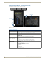
MXT-1900L-PAN (Tabletop).
NFC Sensor
Sleep Button
USB Ports (2)
Cable Slot
FIG. 8 MXT-1900L-PAN - Front View
MXT-1900L-PAN Specifications
MXT-1900L-PAN Specifications
DIMENSIONS (HWD)
7" x 20 3/8" x 5 5/16" (177 mm x 519 mm x 135 mm)
WEIGHT
9.4 lbs (4.26 Kg)
POWER CONSUMPTION
• Full-On: 32W (12 VDC, 2.7 A)
• Standby: 3.10 W (12 VDC, 0.3 A)
• Start-Up Inrush Current: 4.0 A for 80 µsec
EXTERNAL POWER
SUPPLY REQUIRED
Requires one of these AMX power sources (not included):
CERTIFICATIONS
•
•
•
•
•
•
•
•
•
• PSN4.4 Power Supply, 4.4 A, 3.5 mm Phoenix, 13.5 VDC (FG423-45)
• MXA-MPL Modero X/S Series Multi Preview Live (FG5968-10)
• MXA-MP Modero X/S Series Multi Preview (FG5968-20)
FCC Part 15 Class B
CE EN 55022
CE EN 55024
CE EN 60950-1
IEC 60950-1
C-Tick CISPR 22 Class B
IC
UL 60950-1
RoHS/WEEE compliant
Modero X® Series G4 Touch Panels Instruction Manual
15
MXT/D-1900L-PAN - 19.4" X Series Panels
MXT-1900L-PAN Specifications (Cont.)
TOUCH SCREEN DISPLAY
• Display Type: TFT Active Matrix Color LCD with In-plane Switching Technology (IPS)
• Display Size (WH): Landscape 20.4" x 6.9" (519 mm x 175 mm), 20.4" (518 mm)
diagonal
• Viewable Area (WH): Landscape 18.7" x 5.9" (475 mm x 151 mm), 19.4" (493 mm)
diagonal
• Resolution: Landscape 1920x530
• Aspect Ratio: Landscape 18:5
• Brightness: 350 cd/m2
• Contrast Ratio: 1000:1
• Color Depth: 16.7M colors
• Illumination: LED
• Touch Overlay: Projected capacitive, multi-touch support, 3 simultaneous max
VIEWING ANGLE
• Vertical: ± 89°
• Horizontal: ± 89°
MEMORY
• SDRAM: 512 MB
• Flash: 4 GB
• Maximum Project Size: 2.4 GB flash available to user
COMMUNICATIONS
• Ethernet: 10/100 port, RJ-45 connector. Supported IP and IP-based protocols: UCP,
TCP, ICMP, ICSP, IGMP, DHCP, Telnet, FTP, DNS, RFB (for VNC), HTTP
• USB:
(3) USB host 2.0, Type A ports: Firmware upgrade, touch panel file transfer, JPEG
image viewer, HID peripherals, USB audio output for headsets
(1) Micro-USB device port: video output from on-board camera, USB audio from
on-board microphone to host device
• Near Field Communication (NFC): Supports standards ISO/IEC 15693,
ISO/IEC 14443A, ISO/IEC 14443B; Unique Identifier (UID), typ range=.25", max = .5"
• Bluetooth:
Mouse/Keyboard: HID Profile v1.1, requires MXA-BT Bluetooth Adapter (FG5968-19)
Handset: Hands Free Profile v1.5, Headset Profile v1.2, requires MXA-BT Bluetooth
Adapter (FG5968-19) and MXA-HST Bluetooth Handset (FG5968-17)
VIDEO
• Supported Video Codecs:
MPEG2-TS: MPEG-2 Main Profile @High Level up to 720p at 25 fps (decode only)
MPEG-2-TS: H.264 High Profile @Layer 4, AAC-LC up to 720p at 25 fps
(encode/decode)
MJPEG up to 720p at 25 fps (decode only)
• Supported Video Transport Streams: MPEG-TS for MPEG-2 and H.264, HTTP for
MJPEG
• Max Number of Active Video Streams: One decode plus one encode
• Video Output: Camera video output: H.264, up to 720p@25 fps via Micro-USB port only
(controlled by host device)
• Video Conferencing: Panel-to-panel and video chat
AUDIO
• Microphone: -42 dB ±3 dB sensitivity FET microphone
• Speakers: 4 ohm, 2 Watt, 300 Hz cutoff frequency
• Supported Audio Codecs:
MP2 Layer I and II, MP3 (8 kHz, 11.025 kHz, 12 kHz, 16 kHz, 22.05 kHz, 24 kHz,
32 kHz, 44.1 kHz, 48 kHz)
AAC-LC (8 kHz, 96 kHz)
G.711 with µLaw (VoIP encode/decode at 8 kHz)
Suggested max packet size for G.711 Voice: 20ms
• Audio Output: USB Audio out USB port (head/hand set support)
• File Formats: WAV, MP3 (as part of touch panel file only - no USB storage)
• Intercom: Full Duplex VoIP, SIP v2.0 (supported with AMX-CSG)
GRAPHICS ENGINE
16
AMX G4: G4 enhanced feature set supporting multi-touch and gestures, scrolling,
transitions - See TPD4 Operations Guide for more information
Modero X® Series G4 Touch Panels Instruction Manual
MXT/D-1900L-PAN - 19.4" X Series Panels
MXT-1900L-PAN Specifications (Cont.)
EMBEDDED
APPLICATIONS
• Remote Management: VNC Server, G4 Web Control, AMX Resource Management Suite
• Video Conferencing: Panel-to-panel and video chat
• Conferencing: Audio (Full Duplex Intercom)
FRONT PANEL
COMPONENTS
•
•
•
•
•
CONNECTIONS
• Ethernet: 10/100 port, RJ-45 connector
• USB:
(3) USB host 2.0, Type A ports
(1) Micro-USB device port
• Power: 2-pin, locking 3.5mm Phoenix connector
ENVIRONMENTAL
•
•
•
•
•
Light Sensor: Photosensitive light detector for automatic adjustment of the panel brightness
Proximity Detector: Max range = ~3', typ range = ~1', FOV = ~10 degrees
Camera: HD 720p camera for video conferencing/video chat support
LED Indicators: Camera active indicator (models with camera only)
Sleep Button: Sleep button to activate sleep mode and powering off. Also provides
access to setup pages (can be disabled)
Temperature (Operating): 32° F to 104° F (0° C to 40° C)
Temperature (Storage): 4° F to 140° F (-20° C to 60° C)
Humidity (Operating): 20% to 85% RH
Humidity (Storage): 5% to 85% RH
Power ("Heat") Dissipation:
On: 109.2 BTU/hr
Standby: 10.6 BTU/hr
INCLUDED ACCESSORIES •
•
•
•
Locking 2-pin Phoenix mate (41-0002-SA)
MXA-USB-C, USB Port Cover Kit, Modero X/S Series Touch Panel (FG5968-18)
HPG-10-10K, 3/4" Mini-Grommet (FG570-01)
MXA-CLK, Modero X/S Series Cleaning Kit (FG5968-16)
OPTIONAL ACCESSORIES •
•
•
•
•
•
•
•
•
MXA-STMK-19, Secure Table Mount Kit, 19.4" Modero X Tabletop (FG5968-65)
MXA-MP, Modero X/S Series Multi Preview (FG5968-20)
MXA-MPL, Modero X/S Series Multi Preview Live (FG5968-10)
PSN4.4, Power Supply, 4.4 A, 3.5 mm Phoenix, 13.5 VDC (FG423-45)
HPG-10-10K, 3/4" Mini-Grommet, 10-Pack (FG570-01-10K)
MXA-BT, Bluetooth USB Adapter for Modero X/S Series (FG5968-19)
MXA-CLK, Modero X/S Series Cleaning Kit (FG5968-16)
MXA-USB-C, USB Port Covers for the Modero X/S Series Touch Panels (FG5968-18)
MXA-HST, Bluetooth Handset for Modero X/S Series Touch Panels (FG5968-17)
The MXT-1900L-PAN-NC (FG5968-21) "No Comm" touch panel does not have
camera, microphone, NFC or Bluetooth capability; otherwise it has all of the
functionality of the MXT-1900L-PAN.
Modero X® Series G4 Touch Panels Instruction Manual
17
MXT/D-1900L-PAN - 19.4" X Series Panels
MXD-1900L-PAN (Wall Mount-Landscape/Portrait)
The MXD-1900L-PAN is available in Portrait and Landscape layouts:
Portrait
MXD-1900L-PAN-P
FG5968-06
Landscape
MXD-1900L-PAN-L
FG5968-12
NFC Sensor
Sleep Button
Sleep
Button
MXD-1900L-PAN-L
NFC
Sensor
MXD-1900L-PAN-P
FIG. 9 MXD-1900L-PAN, Landscape Wall Mount
MXD-1900L-PAN Specifications
MXD-1900L-PAN Specifications
DIMENSIONS (HWD)
18
• Landscape: 6 7/8" x 20 3/8" x 11/16" (175 mm x 519 mm x 19 mm)
• Portrait: 20 3/8" x 6 7/8" x 11/16" (519 mm x 175 mm x 19 mm)
WEIGHT
7.0 lbs (3.18 Kg)
POWER CONSUMPTION
• Full-On: 32W (12 VDC, 2.7 A)
• Standby: 3.10 W (12 VDC, 0.3 A)
• Start-Up Inrush Current: 4.0 A for 80 µsec
EXTERNAL POWER
SUPPLY REQUIRED
Requires one of these AMX power sources (not included):
• PSN4.4 Power Supply, 4.4 A, 3.5 mm Phoenix, 13.5 VDC (FG423-45)
• MXA-MPL Modero X/S Series Multi Preview Live (FG5968-10)
• MXA-MP Modero X/S Series Multi Preview (FG5968-20)
Modero X® Series G4 Touch Panels Instruction Manual
MXT/D-1900L-PAN - 19.4" X Series Panels
MXD-1900L-PAN Specifications (Cont.)
CERTIFICATIONS
•
•
•
•
•
•
•
•
•
FCC Part 15 Class B
CE EN 55022
CE EN 55024
CE EN 60950-1
IEC 60950-1
C-Tick CISPR 22 Class B
IC
UL 60950-1
RoHS/WEEE compliant
TOUCH SCREEN DISPLAY
• Display Type: TFT Active Matrix Color LCD with In-plane Switching Technology (IPS)
• Display Size (WH)
Landscape: 20.4" x 6.9" (519 mm x 175 mm), 20.4" (518 mm) diagonal
Portrait: 6.9" x 20.4" (175 mm x 519 mm), 20.4" (518 mm) diagonal
• Viewable Area (WH)
Landscape: 18.7" x 5.9" (475 mm x 151 mm), 19.4" (493 mm) diagonal
Portrait: 5.9" x 18.7" (151 mm x 475 mm), 19.4" (493 mm) diagonal
• Resolution
Landscape: 1920x530
Portrait: 530x1920
• Aspect Ratio
Landscape: 18:5
Portrait: 5:18
• Brightness: 350 cd/m2
• Contrast Ratio: 1000:1
• Color Depth: 16.7M colors
• Illumination: LED
• Touch Overlay: Projected capacitive, multi-touch support, 3 simultaneous max
VIEWING ANGLE
• Vertical: ± 89°
• Horizontal: ± 89°
MEMORY
• SDRAM: 512 MB
• Flash: 4 GB
• Maximum Project Size: 2.4 GB flash available to user
COMMUNICATIONS
• Ethernet: 10/100 port, RJ-45 connector. Supported IP and IP-based protocols: UCP,
TCP, ICMP, ICSP, IGMP, DHCP, Telnet, FTP, DNS, RFB (for VNC), HTTP
• USB:
(2) USB host 2.0, Type A ports (1 with limited physical access requiring right angle
connection): Firmware upgrade, touch panel file transfer, JPEG image viewer, HID
peripherals, USB audio output for headsets
(1) Micro-USB device port: video output from on-board camera (Landscape Touch
Panel Only), USB audio from on-board microphone to host device
• Near Field Communication (NFC): Supports standards ISO/IEC 15693,
ISO/IEC 14443A, ISO/IEC 14443B; Unique Identifier (UID), typ range=.25", max = .5"
• Bluetooth:
Mouse/Keyboard: HID Profile v1.1, requires MXA-BT Bluetooth Adapter (FG5968-19)
Handset: Hands Free Profile v1.5, Headset Profile v1.2, requires MXA-BT Bluetooth
Adapter (FG5968-19) and MXA-HST Bluetooth Handset (FG5968-17)
Modero X® Series G4 Touch Panels Instruction Manual
19
MXT/D-1900L-PAN - 19.4" X Series Panels
MXD-1900L-PAN Specifications (Cont.)
VIDEO
• Supported Video Codecs, Landscape Model (FG5968-12):
MPEG-2-TS: MPEG-2 Main Profile@High Level up to 720p at 25 fps (decode only)
MPEG-2-TS: H.264 High Profile@Layer 4, AAC-LC up to 720p at 25 fps
(encode/decode)
MJPEG up to 720p at 25 fps (decode only)
• Supported Video Codecs, Portrait Model (FG5968-06):
MPEG-2-TS: MPEG-2 Main Profile@High Level up to 720p at 25 fps (decode only)
MPEG-2-TS: H.264 High Profile@Layer 4, AAC-LC up to 720p at 25 fps (decode)
MJPEG up to 720p at 25 fps (decode only)
• Supported Video Transport Streams: MPEG-TS for MPEG2 and H.264; HTTP for MJPEG
• Max Number of Active Video Streams:
Portrait: One decode
Landscape: One decode plus one encode
• Video Conferencing, Landscape Model (FG5968-12): Panel-to-panel and video chat
• Video Conferencing, Portrait Model (FG5968-05): Panel-to-panel and video chat
(portrait wall mount receives video and returns audio)
• Video Output, Landscape Model Only (FG5968-12): Camera video output: H.264, up to
720p@25 fps via Micro-USB port only (controlled by host device)
AUDIO
• Microphone: -42 dB ±3 dB sensitivity FET microphone
• Speakers: 4 ohm, 2 Watt, 300 Hz cutoff frequency
• Supported Audio Codecs:
MP2 Layer I and II, MP3 (8 kHz, 11.025 kHz, 12 kHz, 16 kHz, 22.05 kHz, 24 kHz,
32 kHz, 44.1 kHz, 48 kHz)
AAC-LC (8 kHz, 96 kHz)
G.711 with µLaw (VoIP encode/decode at 8 kHz)
Suggested max packet size for G.711 Voice: 20ms
• Audio Output: USB Audio out Micro-USB port (head/hand set support)
• File Formats: WAV, MP3 (as part of touch panel file only - no USB storage)
• Intercom: Full Duplex VoIP, SIP v2.0 (supported with AMX-CSG)
20
GRAPHICS ENGINE
AMX G4: G4 enhanced feature set supporting multi-touch and gestures, scrolling,
transitions - See TPD4 Operations Guide for more information
EMBEDDED
APPLICATIONS
• Remote Management: VNC Server, G4 Web Control, AMX Resource Management
Suite
• Video Conferencing: Panel-to-panel and video chat (portrait wall mount receives video
and returns audio)
• Conferencing: Audio (Full Duplex Intercom)
FRONT PANEL
COMPONENTS
• Light Sensor: Photosensitive light detector for automatic adjustment of the panel
brightness
• Proximity Detector: Max range = ~3', typ range = ~1', FOV = ~10 degrees
• Camera, Landscape Model Only (FG5968-12): HD 720p camera for video conferencing/
video chat support
• LED Indicators: Camera active indicator (models with camera only)
• Sleep Button: Sleep button to activate sleep mode and powering off. Also provides
access to setup pages (can be disabled)
CONNECTIONS
• Ethernet: 10/100 port, RJ-45 connector
• USB:
(2) USB host 2.0, Type A ports
(1) Micro-USB device port
• Power: 2-pin, locking 3.5mm Phoenix connector
ENVIRONMENTAL
•
•
•
•
•
Temperature (Operating): 32° F to 104° F (0° C to 40° C)
Temperature (Storage): 4° F to 140° F (-20° C to 60° C)
Humidity (Operating): 20% to 85% RH
Humidity (Storage): 5% to 85% RH
Power ("Heat") Dissipation:
On: 109.2 BTU/hr
Standby: 10.6 BTU/hr
Modero X® Series G4 Touch Panels Instruction Manual
MXT/D-1900L-PAN - 19.4" X Series Panels
MXD-1900L-PAN Specifications (Cont.)
INCLUDED ACCESSORIES •
•
•
•
Locking 2-pin Phoenix mate (41-0002-SA)
MXA-USB-C, USB Port Cover Kit, Modero X Series Touch Panel (FG5968-18)
MXA-CLK, Modero X Series Cleaning Kit (FG5968-16)
Wall Template 19" (68-5968-02)
OPTIONAL ACCESSORIES •
•
•
•
•
•
•
•
•
•
MXA-FMK-19 Flush Mount Kit, 19.4" Modero X Wall Mount (FG5968-69)
MXA-RMK-19 Modero X Series Rack Mount Kit (FG5969-61)
MXA-MP, Modero X/S Series Multi Preview (FG5968-20)
MXA-MPL, Modero X/S Series Multi Preview Live (FG5968-10)
PSN4.4, Power Supply, 4.4 A, 3.5 mm Phoenix, 13.5 VDC (FG423-45)
CB-MXP19/20, Rough-In Box (FG039-15)
MXA-BT, Bluetooth USB Adapter for Modero X/S Series (FG5968-19)
MXA-CLK, Modero X/S Series Cleaning Kit (FG5968-16)
MXA-USB-C, USB Port Covers for the Modero X Series Touch Panels (FG5968-18)
MXA-HST, Bluetooth Handset for Modero X/S Series Touch Panels (FG5968-17)
The MXD-1900L-PAN-P-NC (FG5968-22) and MXD-1900L-PAN-L-NC (FG5968-23)
"No Comm" touch panels do not have camera, microphone, NFC or Bluetooth
capability; otherwise they have all of the functionality of the MXT/D-2000XL-PAN.
Modero X® Series G4 Touch Panels Instruction Manual
21
MXT/D-1900L-PAN - 19.4" X Series Panels
22
Modero X® Series G4 Touch Panels Instruction Manual
MXT/D-1000 - 10.1" X Series Panels
MXT/D-1000 - 10.1" X Series Panels
MXT-1000 (Tabletop)
NFC Sensor
Sleep Button
USB Ports (2)
FIG. 10 MXT-1000 Touch Panel
MXT-1000 Specifications
MXT-1000 Specifications
DIMENSIONS (HWD)
6 7/8" x 9 7/8" x 4 7/8" (174 mm x 252 mm x 124 mm)
WEIGHT
3.0 lbs (1.36 Kg)
POWER CONSUMPTION
•
•
•
•
EXTERNAL POWER
SUPPLY REQUIRED
Optimal performance requires use of one of the following AMX PoE power supplies (not
included):
Full-On: 8 W
Standby: 3.2 W
Shutdown: 1 W
Start-Up Inrush Current: Not applicable due to PoE standard
• PS-POE-AF-TC, PoE Injector, 802.3AF Compliant (FG423-83)
• NXA-ENET8-2POE, Gigabit PoE Ethernet Switch (FG2178-63)
CERTIFICATIONS
•
•
•
•
•
•
•
•
UL 60950-1
FCC Part 15 Class B
C-Tick CISPR 22 Class B
CE EN 55022, EN 55024 and EN 60950-1
IEC 60950-1
IC
IEC/EN-60950
RoHS/WEEE compliant
Modero X® Series G4 Touch Panels Instruction Manual
23
MXT/D-1000 - 10.1" X Series Panels
MXT-1000 Specifications (Cont.)
TOUCH SCREEN DISPLAY
•
•
•
•
•
•
•
•
•
•
Display Type: TFT Active Matrix Color LCD with In-plane Switching Technology (IPS)
Display Size (WH): 9.9" x 6.7" (252 mm x 170 mm), 12.0" (304 mm) diagonal
Viewable Area (WH): 8.5" x 5.3" (217mm x 136mm), 10.1" (257mm) diagonal
Resolution (WH): 1280x800
Aspect Ratio (WH): 16:9
Brightness: 400 cd/m2
Contrast Ratio: 700:1
Color Depth: 264K colors
Illumination: LED
Touch Overlay: Projected capacitive, multi-touch support, 3 simultaneous max
VIEWING ANGLE
• Vertical: ± 89°
• Horizontal: ± 89°
MEMORY
• SDRAM: 512 MB
• Flash: 4 GB
• Maximum Project Size: 2.4 GB flash available to user
COMMUNICATIONS
• Ethernet: 10/100 Auto MDI-X port, RJ-45 connector. Supported IP and IP-based
protocols: UCP, TCP, ICMP, ICSP, IGMP, DHCP, Telnet, FTP, DNS, RFB (for VNC),
HTTP
• USB:
(2) USB host 2.0, Type A ports (1 with limited physical access requiring right angle
connection): Firmware upgrade, touch panel file transfer, JPEG image viewer, HID
peripherals, USB audio output for headsets
(1) Micro-USB device port: video output from on-board camera (landscape touch
panel only), USB audio from on-board microphone to host device
• Near Field Communication (NFC): Supports standards ISO/IEC 15693,
ISO/IEC 14443A, ISO/IEC 14443B; Unique Identifier (UID), typ range=.25", max = .5"
• Bluetooth:
Mouse/Keyboard: HID Profile v1.1, requires MXA-BT Bluetooth Adapter (FG5968-19)
Handset: Hands Free Profile v1.5, Headset Profile v1.2, requires MXA-BT Bluetooth
Adapter (FG5968-19) and MXA-HST Bluetooth Handset (FG5968-17)
VIDEO
• Supported Video Codecs:
MPEG2-TS: MPEG-2 Main Profile @High Level up to 720p at 25 fps (decode only)
MPEG-2-TS: H.264 High Profile @Layer 4, AAC-LC up to 720p at 25 fps
(encode/decode)
MJPEG up to 720p at 25 fps (decode only)
• Supported Video Transport Streams: MPEG-TS for MPEG-2 and H.264, HTTP for
MJPEG
• Max Number of Active Video Streams: One decode plus one encode
• Video Output: Camera video output: H.264, up to 720p@25 fps via Micro-USB port only
(controlled by host device)
• Video Conferencing: Panel-to-panel and video chat
AUDIO
• Microphone: -42 dB ±3 dB sensitivity FET microphone
• Speakers: 4 ohm, 2 Watt, 300 Hz cutoff frequency
• Supported Audio Codecs:
MP2 Layer I and II, MP3 (8 kHz, 11.025 kHz, 12 kHz, 16 kHz, 22.05 kHz, 24 kHz,
32 kHz, 44.1 kHz, 48 kHz)
AAC-LC (8 kHz, 96 kHz)
G.711 with µLaw (VoIP encode/decode at 8 kHz)
Suggested max packet size for G.711 Voice: 20ms
• Audio Output: USB Audio out USB port (head/hand set support)
• File Formats: WAV, MP3 (as part of touch panel file only - no USB storage)
• Intercom: Full Duplex VoIP, SIP v2.0 (supported with AMX-CSG)
GRAPHICS ENGINE
24
AMX G4: G4 enhanced feature set supporting multi-touch and gestures, scrolling,
transitions - See TPD4 Operations Guide for more information
Modero X® Series G4 Touch Panels Instruction Manual
MXT/D-1000 - 10.1" X Series Panels
MXT-1000 Specifications (Cont.)
EMBEDDED
APPLICATIONS
• Remote Management: VNC Server, G4 Web Control, AMX Resource Management
Suite
• Video Conferencing: Panel-to-panel and video chat
• Audio Conferencing: Audio (Full Duplex Intercom)
FRONT PANEL
COMPONENTS
• Light Sensor: Photosensitive light detector for automatic adjustment of the panel
brightness
• Proximity Detector: Max range = ~3', typ range = ~1', FOV = ~10 degrees
• Camera: HD 720p camera for video conferencing/video chat support
• LED Indicators: Camera active indicator (models with camera only)
• Sleep Button: Sleep button to activate sleep mode and powering off. Also provides
access to setup pages (can be disabled)
CONNECTIONS
• Ethernet: 10/100 Auto MDI-X port, RJ-45 connector through cable extension
• USB:
(2) USB host 2.0, Type A ports
(1) Micro-USB device port
• Power: PoE (Power over Ethernet), 802.3af, class 3
ENVIRONMENTAL
•
•
•
•
•
Temperature (Operating): 32° F to 104° F (0° C to 40° C)
Temperature (Storage): 4° F to 140° F (-20° C to 60° C)
Humidity (Operating): 20% to 85% RH
Humidity (Storage): 5% to 85% RH
Power ("Heat") Dissipation:
On: 21.3 BTU/hr
Standby: 10.6 BTU/hr
INCLUDED ACCESSORIES • MXA-USB-C, USB Port Cover Kit, Modero X/S Series Touch Panel (FG5968-18)
• 3/4" Mini-Grommet (FG570-01)
• MXA-CLK, Modero X/S Series Cleaning Kit (FG5968-16)
OPTIONAL ACCESSORIES •
•
•
•
•
•
•
•
•
•
MXA-STMK-10, Secure Table Mount Kit, 10.1" Modero X Tabletop (FG5968-66)
MXA-MP, Modero X/S Series Multi Preview (FG5968-20)
MXA-MPL, Modero X/S Series Multi Preview Live (FG5968-10)
PS-POE-AF-TC, PoE Injector, 802.3AF Compliant (FG423-83)
HPG-10-10K, 3/4" Mini-Grommet, 10-Pack (FG570-01-10K)
MXA-BT Bluetooth USB Adapter for Modero X/S Series (FG5968-19)
MXA-CLK, Modero X/S Series Cleaning Kit (FG5968-16)
NXA-ENET8-2POE, Gigabit PoE Ethernet Switch (FG2178-63)
MXA-USB-C, USB Port Covers for the Modero X Series Touch Panels (FG5968-18)
MXA-HST, Bluetooth Handset for Modero X/S Series Touch Panels (FG5968-17)
The MXT-1000-NC (FG5968-24) "No Comm" touch panel does not have camera,
microphone, NFC or Bluetooth capability; otherwise it has all of the functionality of
the MXT-1900L-PAN.
Touch Panel Aspect Ratio
While the touch panel screen physical dimensions fall between 16:9 and 16:10, any incoming video stream can be scaled
to 16:9 if needed. This may lead to some letter boxing around the video in some cases.
Modero X® Series G4 Touch Panels Instruction Manual
25
MXT/D-1000 - 10.1" X Series Panels
MXD-1000 (Wall-Mount - Landscape/Portrait)
The MXD-1000 is available in Portrait and Landscape layouts:
Portrait
MXD-1000-P
FG5968-07
Landscape
MXD-1000-L
FG5968-13
NFC Sensor
Sleep Button
Sleep
Button
NFC
Sensor
MXD-1000-P
MXD-1000-L
FIG. 11 MXD-1000 Wall Mount (Portrait and Landscape)
MXD-1000 Specifications
MXD-1000 Specifications
DIMENSIONS (HWD)
• Landscape: 6 11/16" x 9 7/8" x 2 5/8" (171 mm x 252 mm x 67 mm)
• Portrait: 9 7/8" x 6 11/16" x 2 5/8" (252 mm x 171 mm x 67 mm)
WEIGHT
2.0 lbs (0.91 Kg)
POWER CONSUMPTION
•
•
•
•
EXTERNAL POWER
SUPPLY REQUIRED
Optimal performance requires use of one of the following AMX PoE power supplies (not
included):
Full-On: 8 W
Standby: 3.2 W
Shutdown: 1 W
Start-Up Inrush Current: Not applicable due to PoE standard
• PS-POE-AF-TC, PoE Injector, 802.3AF Compliant (FG423-83)
• NXA-ENET8-2POE, Gigabit PoE Ethernet Switch (FG2178-63)
CERTIFICATIONS
26
•
•
•
•
•
•
•
•
UL 60950-1
FCC Part 15 Class B
C-Tick CISPR 22 Class B
CE EN 55022, EN 55024 and EN 60950-1
IEC 60950-1
IC
IEC/EN-60950
RoHS/WEEE compliant
Modero X® Series G4 Touch Panels Instruction Manual
MXT/D-1000 - 10.1" X Series Panels
MXD-1000 Specifications (Cont.)
TOUCH SCREEN DISPLAY
• Display Type: TFT Active Matrix Color LCD with In-plane Switching Technology (IPS)
• Display Size (WH)
Landscape: 9.9" x 6.7" (252 mm x 170 mm), 12.0" (304 mm) diagonal
Portrait: 6.7" x 9.9" (170 mm x 252 mm), 12.0" (304 mm) diagonal
• Viewable Area (WH)
Landscape: 8.5" x 5.3" (217mm x 136mm), 10.1" (257mm) diagonal
Portrait: 5.3" x 8.5" (136 mm x 217 mm), 10.1" (257mm) diagonal
• Resolution
Landscape: 1280x800
Portrait: 800x1280
• Aspect Ratio
Landscape: 16:9
Portrait: 9:16
• Brightness: 400 cd/m2
• Contrast Ratio: 700:1
• Color Depth: 264K colors
• Illumination: LED
• Touch Overlay: Projected capacitive, multi-touch support, 3 simultaneous max
VIEWING ANGLE
• Vertical: ± 89°
• Horizontal: ± 89°
MEMORY
• SDRAM: 512 MB
• Flash: 4 GB
• Maximum Project Size: 2.4 GB flash available to user
COMMUNICATIONS
• Ethernet: 10/100 Auto MDI-X port, RJ-45 connector. Supported IP and IP-based
protocols: UCP, TCP, ICMP, ICSP, IGMP, DHCP, Telnet, FTP, DNS, RFB (for VNC),
HTTP
• USB:
(2) USB host 2.0, Type A ports (1 with limited physical access requiring right angle
connection): Firmware upgrade, touch panel file transfer, JPEG image viewer, HID
peripherals, USB audio output for headsets
(1) Micro-USB device port: video output from on-board camera (landscape touch
panel only), USB audio from on-board microphone to host device
• Near Field Communication (NFC): Supports standards ISO/IEC 15693, ISO/IEC
14443A, ISO/IEC 14443B; Unique Identifier (UID), typ range=.25", max = .5"
• Bluetooth:
Mouse/Keyboard: HID Profile v1.1, requires MXA-BT Bluetooth Adapter (FG5968-19)
Handset: Hands Free Profile v1.5, Headset Profile v1.2, requires MXA-BT Bluetooth
Adapter (FG5968-19) and MXA-HST Bluetooth Handset (FG5968-17)
VIDEO
• Supported Video Codecs, Landscape Model (FG5968-13):
MPEG-2-TS: MPEG-2 Main Profile@High Level up to 720p at 25 fps (decode only)
MPEG-2-TS: H.264 High Profile@Layer 4, AAC-LC up to 720p at 25 fps
(encode/decode)
MJPEG up to 720p at 25 fps (decode only)
• Supported Video Codecs, Portrait Model (FG5968-07):
MPEG-2-TS: MPEG-2 Main Profile@High Level up to 720p at 25 fps (decode only)
MPEG-2-TS: H.264 High Profile@Layer 4, AAC-LC up to 720p at 25 fps (decode)
MJPEG up to 720p at 25 fps (decode only)
• Supported Video Transport Streams: MPEG-TS for MPEG2 and H.264; HTTP for
MJPEG
• Max Number of Active Video Streams:
Portrait: One decode
Landscape: One decode plus one encode
• Video Conferencing, Landscape Model (FG5968-13): Panel-to-panel and video chat
• Video Conferencing, Portrait Model (FG5968-07): Panel-to-panel and video chat (the
portrait wall mount receives video and returns audio)
• Video Output, Landscape Model Only (FG5968-13): Camera video output: H.264, up to
720p@25 fps via Micro-USB port only (controlled by host device)
Modero X® Series G4 Touch Panels Instruction Manual
27
MXT/D-1000 - 10.1" X Series Panels
MXD-1000 Specifications (Cont.)
AUDIO
• Microphone: -42 dB ±3 dB sensitivity FET microphone
• Speakers: 4 ohm, 2 Watt, 300 Hz cutoff frequency
• Supported Audio Codecs:
MP2 Layer I and II, MP3 (8 kHz, 11.025 kHz, 12 kHz, 16 kHz, 22.05 kHz, 24 kHz,
32 kHz, 44.1 kHz, 48 kHz)
AAC-LC (8 kHz, 96 kHz)
G.711 with µLaw (VoIP encode/decode at 8 kHz)
Suggested max packet size for G.711 Voice: 20ms
• Audio Output: USB Audio out USB port (head/hand set support)
• File Formats: WAV, MP3 (as part of touch panel file only - no USB storage)
• Intercom: Full Duplex VoIP, SIP v2.0 (supported with AMX-CSG)
GRAPHICS ENGINE
AMX G4: G4 enhanced feature set supporting multi-touch and gestures, scrolling,
transitions - See TPD4 Operations Guide for more information
EMBEDDED
APPLICATIONS
• Remote Management: VNC Server, G4 Web Control, AMX Resource Management
Suite
• Video Conferencing: Panel-to-panel and video chat
• Audio Conferencing: Audio (Full Duplex Intercom)
FRONT PANEL
COMPONENTS
• Light Sensor: Photosensitive light detector for automatic adjustment of the panel
brightness
• Proximity Detector: Max range = ~3', typ range = ~1', FOV = ~10 degrees
• Camera, Landscape Model Only (FG5968-13): HD 720p camera for video conferencing/
video chat support
• LED Indicators: Camera active indicator (models with camera only)
• Sleep Button: Sleep button to activate sleep mode and powering off. Also provides
access to setup pages (can be disabled)
CONNECTIONS
• Ethernet: 10/100 Auto MDI-X port, RJ-45 connector through cable extension
• USB:
(2) USB host 2.0, Type A ports
(1) Micro-USB device port
• Power: PoE (Power over Ethernet), 802.3af, class 3
ENVIRONMENTAL
•
•
•
•
•
Temperature (Operating): 32° F to 104° F (0° C to 40° C)
Temperature (Storage): 4° F to 140° F (-20° C to 60° C)
Humidity (Operating): 20% to 85% RH
Humidity (Storage): 5% to 85% RH
Power ("Heat") Dissipation:
On: 21.3 BTU/hr
Standby: 10.6 BTU/hr
INCLUDED ACCESSORIES • MXA-USB-C, USB Port Cover Kit, Modero X Series Touch Panel (FG5968-18)
• MXA-CLK, Modero X/S Series Cleaning Kit (FG5968-16)
• Installation Template, 10" Modero X Series (68-5968-03)
OPTIONAL ACCESSORIES •
•
•
•
•
•
•
•
•
•
•
MXA-FMK-10, Flush Mount Kit, 10" Modero X Wall Mount (FG5969-62)
MXA-RMK-10, Modero X Series Rack Mount Kit (FG5969-62)
MXA-MP, Modero X/S Series Multi Preview (FG5968-20)
MXA-MPL, Modero X/S Series Multi Preview Live (FG5968-10)
PS-POE-AF-TC, PoE Injector, 802.3AF Compliant (FG423-83)
CB-MXP10, Rough-In Box (FG039-17)
MXA-BT Bluetooth USB Adapter for Modero X/S Series (FG5968-19)
MXA-CLK, Modero X/S Series Cleaning Kit (FG5968-16)
NXA-ENET8-2POE, Gigabit PoE Ethernet Switch (FG2178-63)
MXA-USB-C, USB Port Cover Kit, Modero X Series Touch Panel (FG5968-18)
MXA-HST, Bluetooth Handset for Modero X Series Touch Panels (FG5968-17)
The MXD-1000-P-NC (FG5968-25) and MXD-1000-L-NC (FG5968-26) "No Comm"
touch panels do not have camera, microphone, NFC or Bluetooth capability;
otherwise they have all of the functionality of the MXT/D-2000XL-PAN.
28
Modero X® Series G4 Touch Panels Instruction Manual
MXT/D-1000 - 10.1" X Series Panels
Touch Panel Aspect Ratio
While the touch panel screen physical dimensions fall between 16:9 and 16:10, any incoming video stream can be scaled
to 16:9 if needed. This may lead to some letter boxing around the video in some cases.
Modero X® Series G4 Touch Panels Instruction Manual
29
MXT/D-1000 - 10.1" X Series Panels
30
Modero X® Series G4 Touch Panels Instruction Manual
MXT/D-700 - 7" X Series Panels
MXT/D-700 - 7" X Series Panels
MXT-700 (Tabletop)
NFC Sensor
Sleep Button
USB Ports (2)
FIG. 12 MXT-700 touch panel
MXT-700 Specifications
MXT-700 Specifications
DIMENSIONS (HWD)
5" x 7 5/16" x 4 1/8" (126 mm x 187 mm x 105 mm)
WEIGHT
1.8 lbs (0.82 Kg)
POWER CONSUMPTION
•
•
•
•
EXTERNAL POWER
SUPPLY REQUIRED
Optimal performance requires use of one of the following AMX PoE power supplies (not
included):
Full-On: 8 W
Standby: 3.2 W
Shutdown: 1 W
Start-Up Inrush Current: Not applicable due to PoE standard
• PS-POE-AF-TC, PoE Injector, 802.3AF Compliant (FG423-83)
• NXA-ENET8-2POE, Gigabit PoE Ethernet Switch (FG2178-63)
CERTIFICATIONS
•
•
•
•
•
•
•
•
UL 60950-1
FCC Part 15 Class B
C-Tick CISPR 22 Class B
CE EN 55022, EN 55024 and EN 60950-1
IEC 60950-1
IC
IEC/EN-60950
RoHS/WEEE compliant
Modero X® Series G4 Touch Panels Instruction Manual
31
MXT/D-700 - 7" X Series Panels
MXT-700 Specifications (Cont.)
TOUCH SCREEN DISPLAY
• Display Type: TFT Active Matrix Color LCD with Fringe Field Switching (FFS) - Wide
Viewing Angle Technology
• Display Size (WH): Landscape: 7.3" x 4.8" (186 mm x 122 mm), 8.8" (222 mm) diagonal
• Viewable Area (WH): Landscape: 6.05" x 3.54" (154 mm x 90 mm), 7.0" (178 mm)
diagonal
• Resolution (WH): Landscape: 1024x600
• Aspect Ratio (WH): Landscape: 16:9
• Brightness: 400 cd/m2
• Contrast Ratio: 800:1
• Color Depth: 16.7M colors
• Illumination: LED
• Touch Overlay: Projected capacitive, multi-touch support, 3 simultaneous max
VIEWING ANGLE
• Vertical: ± 89°
• Horizontal: ± 89°
MEMORY
• SDRAM: 512 MB
• Flash: 4 GB
• Maximum Project Size: 2.4 GB flash available to user
COMMUNICATIONS
• Ethernet: 10/100 Auto MDI-X port, RJ-45 connector. Supported IP and IP-based
protocols: UCP, TCP, ICMP, ICSP, IGMP, DHCP, Telnet, FTP, DNS, RFB (for VNC),
HTTP
• USB: (2) USB host 2.0, Type A ports (1 with limited physical access requiring right angle
connection): Firmware upgrade, touch panel file transfer, JPEG image viewer, HID
peripherals, USB audio output for headsets
• Near Field Communication (NFC): Supports standards ISO/IEC 15693, ISO/IEC
14443A, ISO/IEC 14443B; Unique Identifier (UID), typ range=.25", max = .5"
• Bluetooth:
Mouse/Keyboard: HID Profile v1.1, requires MXA-BT Bluetooth Adapter (FG5968-19)
Handset: Hands Free Profile v1.5, Headset Profile v1.2, requires MXA-BT Bluetooth
Adapter (FG5968-19) and MXA-HST Bluetooth Handset (FG5968-17)
VIDEO
• Supported Video Codecs:
MPEG2-TS: MPEG-2 Main Profile@High Level up to 720p at 25 fps (decode only)
MPEG-2-TS: H.264 High Profile@Layer 4, AAC-LC up to 720p at 25 fps (decode)
MJPEG up to 720p at 25 fps (decode only)
• Supported Video Transport Streams: MPEG-TS for MPEG2 and H.264; HTTP for
MJPEG
• Max Number of Active Video Streams: One decode
AUDIO
• Microphone: -42 dB ±3 dB sensitivity FET microphone
• Speakers: 4 ohm, 2 Watt, 300 Hz cutoff frequency
• Supported Audio Codecs:
MP2 Layer I and II, MP3 (8 kHz, 11.025 kHz, 12 kHz, 16 kHz, 22.05 kHz, 24 kHz,
32 kHz, 44.1 kHz, 48 kHz)
AAC-LC (8 kHz, 96 kHz)
G.711 with µLaw (VoIP encode/decode at 8 kHz)
Suggested max packet size for G.711 Voice: 20ms
• Audio Output: USB Audio out USB port (head/hand set support)
• File Formats: WAV, MP3 (as part of touch panel file only - no USB storage)
• Intercom: Full Duplex VoIP, SIP v2.0 (supported with AMX-CSG)
32
GRAPHICS ENGINE
AMX G4: G4 enhanced feature set supporting multi-touch and gestures, scrolling,
transitions - See TPD4 Operations Guide for more information
EMBEDDED
APPLICATIONS
• Remote Management: VNC Server, G4 Web Control, AMX Resource Management
Suite
• Video Conferencing: Panel-to-panel and video chat (the MXT-700 receives video and
returns audio)
• Audio Conferencing: Audio (Full Duplex Intercom)
Modero X® Series G4 Touch Panels Instruction Manual
MXT/D-700 - 7" X Series Panels
MXT-700 Specifications (Cont.)
FRONT PANEL
COMPONENTS
• Light Sensor: Photosensitive light detector for automatic adjustment of the panel
brightness
• Proximity Detector: Max range = ~3', typ range = ~1', FOV = ~10 degrees
• Sleep Button: Sleep button to activate sleep mode and powering off. Also provides
access to setup pages (can be disabled)
CONNECTIONS
• Ethernet: 10/100 Auto MDI-X port, RJ-45 connector through cable extension
• USB: (2) USB host 2.0, Type A ports
• Power: PoE (Power over Ethernet), 802.3af, class 3
ENVIRONMENTAL
•
•
•
•
•
Temperature (Operating): 32° F to 104° F (0° C to 40° C)
Temperature (Storage): 4° F to 140° F (-20° C to 60° C)
Humidity (Operating): 20% to 85% RH
Humidity (Storage): 5% to 85% RH
Power ("Heat") Dissipation:
On: 18.5 BTU/hr
Standby: 10.6 BTU/hr
INCLUDED ACCESSORIES • MXA-USB-C, USB Port Cover Kit, Modero X/S Series Touch Panel (FG5968-18)
• 3/4" Mini-Grommet (FG570-01)
• MXA-CLK, Modero X/S Series Cleaning Kit (FG5968-16)
OPTIONAL ACCESSORIES •
•
•
•
•
•
•
•
•
MXA-MP, Modero X/S Series Multi Preview (FG5968-20)
MXA-MPL, Modero X/S Series Multi Preview Live (FG5968-10)
PS-POE-AF-TC, PoE Injector, 802.3AF Compliant (FG423-83)
HPG-10-10K, 3/4" Mini-Grommet, 10-Pack (FG570-01-10K)
MXA-BT Bluetooth USB Adapter for Modero X/S Series (FG5968-19)
MXA-CLK, Modero X/S Series Cleaning Kit (FG5968-16)
NXA-ENET8-2POE, Gigabit PoE Ethernet Switch (FG2178-63)
MXA-HST, Bluetooth Handset for Modero X/S Series Touch Panels (FG5968-17)
MXA-USB-C, USB Port Covers for the Modero X/S Series Touch Panels (FG5968-18)
The MXT-700-NC (FG5968-27) "No Comm" touch panel does not have camera,
microphone, NFC or Bluetooth capability; otherwise it has all of the functionality of
the MXT-700.
Touch Panel Aspect Ratio
While the touch panel screen physical dimensions fall between 16:9 and 16:10, any incoming video stream can be scaled
to 16:9 if needed. This may lead to some letter boxing around the video in some cases.
Modero X® Series G4 Touch Panels Instruction Manual
33
MXT/D-700 - 7" X Series Panels
MXD-700 (Wall-Mount - Landscape/Portrait)
The MXD-700 is available in Portrait and Landscape layouts: .
Portrait
MXD-700-P
FG5968-08
Landscape
MXD-700-L
FG5968-14
NFC Sensor
Sleep Button
Sleep Button
NFC
Sensor
MXD-700-P
MXD-700-L
FIG. 13 MXD-700 Wall Mount (Portrait and Landscape)
MXD-700 Specifications
MXD-700 Specifications
DIMENSIONS (HWD)
• Landscape: 4 13/16" x 7 5/16" x 2 1/2" (122 mm x 186 mm x 63 mm)
• Portrait: 7 5/16" x 4 13/16" x 2 1/2" (186 mm x 122 mm x 63 mm)
WEIGHT
1.4 lbs (0.64 Kg)
POWER CONSUMPTION
•
•
•
•
EXTERNAL POWER
SUPPLY REQUIRED
Optimal performance requires use of one of the following AMX PoE power supplies (not
included):
Full-On: 8 W
Standby: 3.2 W
Shutdown: 1 W
Start-Up Inrush Current: Not applicable due to PoE standard
• PS-POE-AF-TC, PoE Injector, 802.3AF Compliant (FG423-83)
• NXA-ENET8-2POE, Gigabit PoE Ethernet Switch (FG2178-63)
CERTIFICATIONS
34
•
•
•
•
•
•
•
•
UL 60950-1
FCC Part 15 Class B
C-Tick CISPR 22 Class B
CE EN 55022, EN 55024 and EN 60950-1
IEC 60950-1
IC
IEC/EN-60950
RoHS/WEEE compliant
Modero X® Series G4 Touch Panels Instruction Manual
MXT/D-700 - 7" X Series Panels
MXD-700 Specifications (Cont.)
TOUCH SCREEN DISPLAY
• Display Type: TFT Active Matrix Color LCD with Fringe Field Switching (FFS) - Wide
Viewing Angle Technology
• Display Size (WH)
Landscape: 7.3" x 4.8" (186 mm x 122 mm), 8.8" (222 mm) diagonal
Portrait: 4.8" x 7.3" (122 mm x 186 mm), 8.8" (222 mm) diagonal
• Viewable Area (WH)
Landscape: 6.05" x 3.54" (154 mm x 90 mm), 7.0" (178 mm) diagonal
Portrait: 3.54" x 6.05" (90 mm x 154 mm), 7.0" (178 mm) diagonal
• Resolution
Landscape: 1024x600
Portrait: 600x1024
• Aspect Ratio
Landscape: 16:9
Portrait: 9:16
• Brightness: 400 cd/m2
• Contrast Ratio: 800:1
• Color Depth: 16.7M colors
• Illumination: LED
• Touch Overlay: Projected capacitive, multi-touch support, 3 simultaneous max
VIEWING ANGLE
• Vertical: ± 89°
• Horizontal: ± 89°
MEMORY
• SDRAM: 512 MB
• Flash: 4 GB
• Maximum Project Size: 2.4 GB flash available to user
COMMUNICATIONS
• Ethernet: 10/100 Auto MDI-X port, RJ-45 connector. Supported IP and IP-based
protocols: UCP, TCP, ICMP, ICSP, IGMP, DHCP, Telnet, FTP, DNS, RFB (for VNC),
HTTP
• USB: (2) USB host 2.0, Type A ports (1 with limited physical access requiring right angle
connection): Firmware upgrade, touch panel file transfer, JPEG image viewer, HID
peripherals, USB audio output for headsets
• Near Field Communication (NFC): Supports standards ISO/IEC 15693, ISO/IEC
14443A, ISO/IEC 14443B; Unique Identifier (UID), typ range=.25", max = .5"
• Bluetooth:
Mouse/Keyboard: HID Profile v1.1, requires MXA-BT Bluetooth Adapter (FG5968-19)
Handset: Hands Free Profile v1.5, Headset Profile v1.2, requires MXA-BT Bluetooth
Adapter (FG5968-19) and MXA-HST Bluetooth Handset (FG5968-17)
VIDEO
• Supported Video Codecs:
MPEG2-TS: MPEG-2 Main Profile@High Level up to 720p at 25 fps (decode only)
MPEG-2-TS: H.264 High Profile@Layer 4, AAC-LC up to 720p at 25 fps (decode)
MJPEG up to 720p at 25 fps (decode only)
• Supported Video Transport Streams: MPEG-TS for MPEG2 and H.264; HTTP for
MJPEG
• Max Number of Active Video Streams: One decode
AUDIO
• Microphone: -42 dB ±3 dB sensitivity FET microphone
• Speakers: 4 ohm, 2 Watt, 300 Hz cutoff frequency
• Supported Audio Codecs:
MP2 Layer I and II, MP3 (8 kHz, 11.025 kHz, 12 kHz, 16 kHz, 22.05 kHz, 24 kHz,
32 kHz, 44.1 kHz, 48 kHz)
AAC-LC (8 kHz, 96 kHz)
G.711 with µLaw (VoIP encode/decode at 8 kHz)
Suggested max packet size for G.711 Voice: 20ms
• Audio Output: USB Audio out USB port (head/hand set support)
• File Formats: WAV, MP3 (as part of touch panel file only - no USB storage)
• Intercom: Full Duplex VoIP, SIP v2.0 (supported with AMX-CSG)
GRAPHICS ENGINE
AMX G4: G4 enhanced feature set supporting multi-touch and gestures, scrolling,
transitions - See TPD4 Operations Guide for more information
Modero X® Series G4 Touch Panels Instruction Manual
35
MXT/D-700 - 7" X Series Panels
MXD-700 Specifications (Cont.)
EMBEDDED
APPLICATIONS
• Remote Management: VNC Server, G4 Web Control, AMX Resource Management
Suite
• Video Conferencing: Panel-to-panel and video chat (the MXD-700 receives video and
returns audio)
• Audio Conferencing: Audio (Full Duplex Intercom)
FRONT PANEL
COMPONENTS
• Light Sensor: Photosensitive light detector for automatic adjustment of the panel
brightness
• Proximity Detector: Max range = ~3', typ range = ~1', FOV = ~10 degrees
• Sleep Button: Sleep button to activate sleep mode and powering off. Also provides
access to setup pages (can be disabled)
CONNECTIONS
• Ethernet: 10/100 Auto MDI-X port, RJ-45 connector through cable extension
• USB: (2) USB host 2.0, Type A ports
• Power: PoE (Power over Ethernet), 802.3af, class 3
ENVIRONMENTAL
•
•
•
•
•
Temperature (Operating): 32° F to 104° F (0° C to 40° C)
Temperature (Storage): 4° F to 140° F (-20° C to 60° C)
Humidity (Operating): 20% to 85% RH
Humidity (Storage): 5% to 85% RH
Power ("Heat") Dissipation:
On: 18.5 BTU/hr
Standby: 10.6 BTU/hr
INCLUDED ACCESSORIES • MXA-USB-C, USB Port Cover Kit, Modero X Series Touch Panel (FG5968-18)
• MXA-CLK, Modero X/S Series Cleaning Kit (FG5968-16)
• Installation Template, 7" Modero X Series (68-5968-04)
OPTIONAL ACCESSORIES •
•
•
•
•
•
•
•
•
•
•
•
MXA-FMK-07 Flush Mount Kit, 7" Modero X Wall Mount (FG5968-71)
MXA-RMK-07 Modero X Series Rack Mount Kit (FG5969-63)
MXA-MP, Modero X/S Series Multi Preview (FG5968-20)
MXA-MPL, Modero X/S Series Multi Preview Live (FG5968-10)
PS-POE-AF-TC, PoE Injector, 802.3AF Compliant (FG423-83)
CB-MXSA-07, Rough-In Box, Modero X/S Series Touch Panel, 7" (FG039-18)
CB-MXP7, Rough-In Box (FG039-18)
MXA-BT Bluetooth USB Adapter for Modero X/S Series (FG5968-19)
MXA-CLK, Modero X/S Series Cleaning Kit (FG5968-16)
NXA-ENET8-2POE, Gigabit PoE Ethernet Switch (FG2178-63)
MXA-USB-C, USB Port Cover Kit, Modero X Series Touch Panel (FG5968-18)
MXA-HST, Bluetooth Handset for Modero X/S Series Touch Panels (FG5968-17)
The MXD-700-P-NC (FG5968-28) and MXD-700-L-NC (FG5968-29) "No Comm"
touch panels do not have camera, microphone, NFC or Bluetooth capability;
otherwise they have all of the functionality of the MXT/D-700.
Touch Panel Aspect Ratio
While the touch panel screen physical dimensions fall between 16:9 and 16:10, any incoming video stream can be scaled
to 16:9 if needed. This may lead to some letter boxing around the video in some cases.
36
Modero X® Series G4 Touch Panels Instruction Manual
MXD-430 - 4.3” X Series Panels
MXD-430 - 4.3” X Series Panels
MXD-430 4.3" Modero X Series Wall/Flush Mount Touch Panel
Left LED
Right LED
Sleep
Button
USB
Port
RJ45
Port
NFC
Sensor
front
rear
FIG. 14 MXD-430
MXD-430 Specifications
MXD-430 Specifications
DIMENSIONS (HWD)
Portrait: 4 7/8" x 3 1/4" x 2 3/8" (120 mm x 82 mm x 61 mm)
WEIGHT
0.75 lbs (.34 Kg
POWER CONSUMPTION
•
•
•
•
EXTERNAL POWER
SUPPLY REQUIRED
Optimal performance requires use of one of the following AMX PoE power supplies (not
included):
Full-On: 6.5 W
Standby: 4.2 W
Shutdown: 1.9 W
Start-Up Inrush Current: Not applicable due to PoE standard
• PS-POE-AF-TC, PoE Injector, 802.3AF Compliant (FG423-83)
• NXA-ENET8-2POE, Gigabit PoE Ethernet Switch (FG2178-63)
CERTIFICATIONS
•
•
•
•
•
•
•
•
UL 60950-1
FCC Part 15 Class B
C-Tick CISPR 22 Class B
CE EN 55022, EN 55024 and EN 60950-1
IEC 60950-1
IC
IEC/EN-60950
RoHS / WEEE compliant
Modero X® Series G4 Touch Panels Instruction Manual
37
MXD-430 - 4.3” X Series Panels
MXD-430 Specifications (Cont.)
TOUCH SCREEN DISPLAY
•
•
•
•
•
•
•
•
•
•
Display Type: TFT Active Matrix Color LCD with In-plane Switching Technology (IPS)
Display Size (WH): Portrait: 3.3" x 4.8" (82 mm x 120 mm), 4.9" (119 mm) diagonal
Viewable Area (WH): Portrait: 2.2" x 3.7" (56 mm x 94 mm), 4.3" (109 mm) diagonal
Resolution: Portrait: 480x800
Aspect Ratio: Portrait: 9:16
Brightness: 500 cd/m2
Contrast Ratio: 1000:1
Color Depth: 16.7M colors
Illumination: LED
Touch Overlay: Projected capacitive, multi-touch support, 3 simultaneous max
VIEWING ANGLE
• Vertical: ± 80°
• Horizontal: ± 80°
MEMORY
• SDRAM: 512 MB
• Flash: 4 GB
• Maximum Project Size: 2.4 GB flash available to user
COMMUNICATIONS
• Ethernet: 10/100 Auto MDI-X port, RJ-45 connector. Supported IP and IP-based
protocols: UCP, TCP, ICMP, ICSP, IGMP, DHCP, Telnet, FTP, DNS, RFB (for VNC),
HTTP
• USB: (1) USB host 2.0, Type A port: Firmware upgrade, touch panel file transfer, JPEG
image viewer
• Near Field Communication (NFC): Supports standards ISO/IEC 15693, ISO/IEC
14443A, ISO/IEC 14443B; Unique Identifier (UID), typ range=.25", max = .5"
• Bluetooth:
Mouse/Keyboard: HID Profile v1.1, requires MXA-BT Bluetooth Adapter (FG5968-19)
Handset: Hands Free Profile v1.5, Headset Profile v1.2, requires MXA-BT Bluetooth
Adapter (FG5968-19) and MXA-HST Bluetooth Handset (FG5968-17)
VIDEO
• Supported Video Codecs:
MPEG2-TS: MPEG-2 Main Profile@High Level up to 720p at 25 fps (decode only)
MPEG-2-TS: H.264 High Profile@Layer 4, AAC-LC up to 720p at 25 fps (decode)
MJPEG up to 720p at 25 fps (decode only)
• Supported Video Transport Streams: MPEG-TS for MPEG2 and H.264; HTTP for
MJPEG
• Max Number of Active Video Streams: One decode
AUDIO
• Microphone: -42 dB ±3 dB sensitivity FET microphone
• Speakers: 4 ohm, 2 Watt, 300 Hz cutoff frequency
• Supported Audio Codecs:
MP2 Layer I and II, MP3 (8 kHz, 11.025 kHz, 12 kHz, 16 kHz, 22.05 kHz, 24 kHz,
32 kHz, 44.1 kHz, 48 kHz)
AAC-LC (8 kHz, 96 kHz)
G.711 with µLaw (VoIP encode/decode at 8 kHz)
Suggested max packet size for G.711 Voice: 20ms
• Audio Output: USB Audio out USB port (head/hand set support)
• File Formats: WAV, MP3 (as part of touch panel file only - no USB storage)
• Intercom: Full Duplex VoIP, SIP v2.0 (supported with AMX-CSG)
38
GRAPHICS ENGINE
AMX G4: G4 enhanced feature set supporting multi-touch and gestures, scrolling,
transitions - See TPD4 Operations Guide for more information.
EMBEDDED
APPLICATIONS
• Remote Management: VNC Server, G4 Web Control, AMX Resource Management
Suite
• Video Conferencing: Panel-to-panel and video chat (the MXD-430 receives video and
returns audio)
• Audio Conferencing: Audio (Full Duplex Intercom)
Modero X® Series G4 Touch Panels Instruction Manual
MXD-430 - 4.3” X Series Panels
MXD-430 Specifications (Cont.)
FRONT PANEL
COMPONENTS
• Light Sensor: Photosensitive light detector for automatic adjustment of the panel
brightness
• Proximity Detector: Max range = ~3', typ range = ~1', FOV = ~10 degrees
• Sleep Button: Sleep button to activate sleep mode and powering off. Also provides
access to setup pages (can be disabled)
• Programmable Red/Green LEDs: Programmable red/green LED recessed in the left
and right sides of the panel
CONNECTIONS
• Ethernet: 10/100 Auto MDI-X port, RJ-45 connector through cable extension
• USB: (1) USB host 2.0, Type A port
• Power: PoE (Power over Ethernet), 802.3af, class 3
ENVIRONMENTAL
•
•
•
•
•
Temperature (Operating): 32° F to 104° F (0° C to 40° C)
Temperature (Storage): 4° F to 140° F (-20° C to 60° C)
Humidity (Operating): 20% to 85% RH
Humidity (Storage): 5% to 85% RH
Power ("Heat") Dissipation:
On: 22.2 BTU/hr
Standby: 14.3 BTU/hr
INCLUDED ACCESSORIES • MXA-USB-C, USB Port Cover Kit, Modero X Series Touch Panel (FG5968-18)
• MXA-CLK, Modero X/S Series Cleaning Kit (FG5968-16)
• Installation Template, 4.3" Modero X Series (68-5968-05)
OPTIONAL ACCESSORIES • MXA-FMK-43, Flush Mount Kit for 4.3" Modero X Series Wall Mount Touch Panel
(FG5968-72)
• MXA-MP, Modero X/S Series Multi Preview (FG5968-20)
• MXA-MPL, Modero X/S Series Multi Preview Live (FG5968-10)
• PS-POE-AF-TC, PoE Injector, 802.3AF Compliant (FG423-83)
• CB-MXP43, Rough-In Box (FG039-19)
• MXA-BT Bluetooth USB Adapter for Modero X/S Series (FG5968-19)
• MXA-CLK, Modero X/S Series Cleaning Kit (FG5968-16)
• NXA-ENET8-2POE, Gigabit PoE Ethernet Switch (FG2178-63)
• MXA-USB-C, USB Port Cover Kit, Modero X Series Touch Panel (FG5968-18)
• MXA-HST, Bluetooth Handset for Modero X/S Series Touch Panels (FG5968-17)
Modero X® Series G4 Touch Panels Instruction Manual
39
MXD-430 - 4.3” X Series Panels
40
Modero X® Series G4 Touch Panels Instruction Manual
Installing Tabletop (MXT) Panels
Installing Tabletop (MXT) Panels
MXT-2000XL-PAN / MXT-1900L-PAN
Detailed specifications drawings for the MXT-2000XL-PAN and MXT-1900L-PAN are available to download from
www.amx.com.
Connector Locations - MXT-2000XL-PAN / MXT-1900L-PAN
Two Type A USB ports are located on the rear right corner of the panel (FIG. 15). USB peripherals (i.e. mouse,
keyboard) may be connected to either of the two USB ports on the rear of the device. Note that FIG. 15 shows the
MXT-1900L-PAN, but the USB ports are in a similar location on the MXT-2000XL-PAN.
Type A USB Ports
FIG. 15 MXT-1900L-PAN - rear view
The Power and Ethernet connectors, as well as an additional USB port are located on the bottom of the device ( FIG. 16).
12 VDC Power Port
Ethernet 10/100 Port
Type A USB Port
FIG. 16 MXT-2000XL-PAN / MXT-1900L-PAN - underside connectors
Refer to the Power via 12 VDC section on page 42 for details on wiring a power
connection.
The underside USB port, as well as the two rear USB ports, may be used with a flash drive for page transfers or firmware
upgrades.
The MXT-2000XL-PAN and MXT-1900L-PAN have a slot at the base with channels for securing power and Ethernet
cables, to allow options for cable configuration (FIG. 17).
Ferrite
Tie-wrap
Tie-wrap channels
FIG. 17 Tie-wrap for power connector ferrite
Each channel side has slots for attaching tie-wraps to secure each cable.
The ferrite on the power cable must be secured with the included tie-wrap during installation to prevent the
possibility of the panel not sitting flush on the table.
Other cables may be secured with tie-wraps if desired.
Modero X® Series G4 Touch Panels Instruction Manual
41
Installing Tabletop (MXT) Panels
MXT-1000 / MXT-700
Detailed specifications drawings for the MXT-1000 and MXT-700 are available to download from www.amx.com.
Connector Locations - MXT-1000/MXT-700
Two Type A USB ports are located on the rear right corner of the panel (FIG. 18). USB peripherals (i.e. mouse,
keyboard) may be connected to either of the two USB ports on the rear of the device. Updates to the device’s firmware
can also made via the USB ports (see Upgrading Firmware via USB Flash Drive on page 41 for details). Note that
FIG. 18 shows the MXT-1000, but the USB ports are in a similar location on the MXT-700.
USB Ports
Entry for RJ45/PoE Cable
FIG. 18 MXT-1000 - rear view
Refer to the Power via PoE section on page 43 for details on PoE and Ethernet Cable
Installation and Modification.
Power via 12 VDC
The MXT-2000XL-PAN and MXT-1900L-PAN use a 12 VDC-compliant power supply to provide power to the panel via
the 2-pin 3.5 mm captive wire PWR connector. The incoming PWR and GND wires from the power supply must be
connected to the corresponding locations within the PWR connector.
Connecting power to the panel should be done using the included 2-pin 3.5mm
captive wire connector included with the device. This connector is retained within its
port with locking screws instead of the pins on each side of standard captive wire
connectors, and using force to insert a standard captive wire connector may damage
the device.
Wiring a 12VDC Power Connection
To use the 2-pin 3.5 mm captive wire connector with a 12 VDC-compliant power supply, the incoming PWR and GND
wires from the external source must be connected to their corresponding locations on the connector (FIG. 19). The
connector uses locking screws to insure a connection to the device, so make sure to insert and tighten the screws before
applying power.
PWR +
Power Supply
GND To the Touch Panel
FIG. 19 NetLinx power connector wiring diagram
1. Insert the PWR and GND wires on the terminal end of the 2-pin 3.5 mm captive wire cable.
Match the wiring locations of the +/- on both the power supply and the terminal connector.
2. Tighten the clamp to secure the two wires.
42
Modero X® Series G4 Touch Panels Instruction Manual
Installing Tabletop (MXT) Panels
Do not tighten the screws excessively; doing so may strip the threads and damage the connector.
3. Verify the connection of the 2-pin 3.5 mm captive wire to the external 12 VDC-compliant power supply and apply
power.
Power via PoE
Power for the MXT-1000 and MXT-700 is supplied via PoE (Power Over Ethernet ), utilizing an AMX-certified,
capacitive touch-compliant PoE injector such as the PS-POE-AT High Power PoE Injector (FG423-81) or other
approved AMX PoE power source.
The incoming Ethernet cable should be connected to the RJ45 port on the cable attached to the device.
Ethernet Cable Installation and Modification
In tabletop installations where concealing the Ethernet cable is desired, a hole at least 1.00” (2.54 cm) in diameter is
required in the surface to allow passage of the female RJ45 connector (FIG. 20). If using a smaller hole is unavoidable,
you will need to disconnect the Ethernet cable (ECA5968-05) from the device, to feed the male end of the cable through.
Ethernet Cable
Clamp
Connector
FIG. 20 Bottom of the MXT-700/1000
The minimum diameter hole through which the Ethernet cable may pass is 0.50"
(1.27 cm).
To disconnect and reconnect the Ethernet cable on the MXT-700 and MXT-1000 to allow use of a hole smaller than
1.00” in diameter:
1. On a soft surface, turn the MXT-1000 face-down to access the bottom of the device.
2. Remove the clamp holding the Ethernet cable (FIG. 20).
3. Remove the Ethernet cable connector and pull the cable out of the clamp.
4. Pass the Ethernet cable (ECA5968-05) through the hole, with the RJ45 connector on the other side of the
installation surface from the device.
5. Press the Ethernet cable back into the clamp.
Do NOT tighten the clamp at this time.
6. Using a non-conductive item such as a wooden stick, reinsert the Ethernet cable connector into the device. Ensure
that the connector is properly seated.
7. Tighten the clamp to secure the Ethernet cable.
Make sure the clamp is around the bundled black cable, not the individual wires
8. Connect the RJ45 connector to its incoming Ethernet cable and apply power.
Modero X® Series G4 Touch Panels Instruction Manual
43
Installing Tabletop (MXT) Panels
44
Modero X® Series G4 Touch Panels Instruction Manual
Installing Wall-Mount (MXD) Panels
Installing Wall-Mount (MXD) Panels
A Note About Wall and Rack Installation
AMX DEVICE
Some products are installed in areas of differing temperature and cooling methodologies. These include products
installed in walls, racks, cabinets, etc. Those areas may have different temperatures and/or cooling approaches that must
be taken into consideration to maintain the product within the specified operating temperature.
FIG. 21 shows an AMX device installed in a wall with a filled volume (such as with insulation or concrete), as well as
with a closed volume (such as between studs in an otherwise finished wall). The diagram shows how heat generated by
the device or other devices may have no way to escape, and may build up to levels that may affect device operation.
T1
T2
FILLED OR CLOSED
VOLUME, LIMITED OR
NO CONVECTION
T1, T2 < TOpMax
T1, T2 > TOpMin
FIG. 21 Heat convection in filled or closed volume, limited or no convection
In FIG. 22, the diagram displays an AMX device in a typical rack mounting, with full air circulation around the front and
back of the device. In this case, the main concern is with heat building up between components, possibly to levels that
may affect device operation.
T3
T1
AMX DEVICE
T2
T4
RACK MOUNTED DEVICES
T1, T2, T3, T4 < TOpMax
T1, T2, T3, T4 > TOpMin
FIG. 22 Heat convection in rack-mounted devices
Modero X® Series G4 Touch Panels Instruction Manual
45
Installing Wall-Mount (MXD) Panels
Installation Recommendations
During any installation, a lack of ventilation may produce conditions that may adversely affect the device’s operation. In
these circumstances, special care must be made to make sure that temperatures within enclosed areas do not exceed the
device’s maximum rated temperature.
While the outside temperature of the device may be at or below its maximum
operating temperature, special care must be taken before and during installation to
ensure that the maximum operating temperature is not exceeded within wall or rack
installation spaces.
MXD-2000XL-PAN / MXD-1900L-PAN Installation
Refer to A Note About Wall and Rack Installation on page 45 for important notes
on thermal concerns with Wall and Rack Installations.
Note that the figures in this section show landscape (-L) panels, but the concepts presented here apply equally to portrait
(-P) panels, since the hardware is the same for landscape and portrait panels except for the horizontal / vertical
orientation. Detailed specifications drawings for the MXD-2000XL-PAN and MXD-1900L-PAN (portrait and
landscape) are available to download from www.amx.com.
MXD-2000XL-PAN and MXD-1900L-PAN panels may be installed directly into a solid surface, using either solid
surface screws or the included locking tabs for different mounting options.
Once installed, the panel is contained within a clear outer housing known as the Backbox (FIG. 23). This Backbox is
removed when installing the device into a wall or when using the optional Rough-In Box accessory (FG039-15).
Temporary Mounting Posts
Locking Tabs
Locking Tabs
Temporary Mounting Posts
FIG. 23 Backbox (MXD-2000XL-PAN / MXD-1900L-PAN)
For typical mounting surfaces, such as drywall, use the locking tabs as the primary
method for securing the Backbox to the surface. For thin walls or solid surfaces, use
mounting screws (not included).
46
Modero X® Series G4 Touch Panels Instruction Manual
Installing Wall-Mount (MXD) Panels
Installing the MXD-2000XL-PAN / MXD-1900L-PAN Into a Wall
The Backbox has four locking tabs (two on top and two on bottom) to lock the Backbox to the wall (FIG. 24).
Note that FIG. 24 shows the MXD-1900L-PAN, but the locking tabs are in a similar location on the MXT-2000XL-PAN.
Backbox knockouts (X8)
Locking tabs (X4)
Backbox
FIG. 24 MXD-1900L-PAN (Landscape)
These locking tabs are only extended AFTER the Backbox is inserted into the wall.
The Backbox also has four slots for accepting the temporary mounting posts on the back of the device.
When installing the Backbox, make sure that the assembly is in the correct position
and in the correct place. Once the locking tabs are extended and locked into place,
removing the Backbox may be difficult without having access to the back of the wall
or causing damage to the wall.
Modero X® Series G4 Touch Panels Instruction Manual
47
Installing Wall-Mount (MXD) Panels
MXD-2000XL-PAN Dimensions
FIG. 25 provides dimensions for the MXD-2000XL-PAN:
Notes:
Dimensions in parenthesis are in millimeters
Additional detailed installation and product drawings are available to view/download at www.amx.com
FIG. 25 MXD-2000XL-PAN - Dimensions
48
Modero X® Series G4 Touch Panels Instruction Manual
Installing Wall-Mount (MXD) Panels
MXD-1900L-PAN Dimensions
FIG. 26 provides dimensions for the MXD-1900L-PAN:
Notes:
Dimensions in parenthesis are in millimeters
Additional detailed installation and product drawings are available to view/download at www.amx.com
FIG. 26 MXD-1900L-PAN - Dimensions
In order to ensure a stable installation, the thickness of the wall material must be a
minimum of .50 inches (1.27cm) and a maximum of .875 inches (2.22cm).
Modero X® Series G4 Touch Panels Instruction Manual
49
Installing Wall-Mount (MXD) Panels
Installing the Backbox
MXD-2000XL-PAN Installation Dimensions
FIG. 27 and FIG. 28 provide installation dimensions for the MXD-2000XL-PAN:
FIG. 27 MXD-2000XL-PAN-L Installation Dimensions (front view)
Notes:
- Dimensions in parenthesis are in millimeters.
- These drawings show a Landscape panel. The dimensions
are the same for Portrait panels, except for the vertical orientation.
Additional detailed installation and product drawings (for both
Landscape and Portrait versions are available to view/download
at www.amx.com
FIG. 28 MXD-2000XL-PAN-L Installation Dimensions (side view)
50
Modero X® Series G4 Touch Panels Instruction Manual
Installing Wall-Mount (MXD) Panels
MXD-1900L-PAN Installation Dimensions
FIG. 29 and FIG. 30 provide installation dimensions for the MXD-1900L-PAN:
FIG. 29 MXD-1900L-PAN-L Installation Dimensions (front view)
Notes:
- Dimensions in parenthesis are in millimeters.
- These drawings show a Landscape panel. The dimensions
are the same for Portrait panels, except for the vertical orientation.
Additional detailed installation and product drawings (for both
Landscape and Portrait versions are available to view/download
at www.amx.com
FIG. 30 MXD-1900L-PAN-L Installation Dimensions (side view)
Since the cutout for the Backbox is off-center from the edges of the touch panel, use the included Installation Template to
ensure proper placement.
Using the Installation Template to select the final placement of the Backbox is highly
recommended. The outside edges of the template are the same dimensions as the
touch panel, which allows you to troubleshoot possible conflicts with wall edges,
doors, and other potential obstacles.
The MXD-2000XL-PAN uses Installation Template 68-5968-01
The MXD-1900L-PAN uses Installation Template 68-5968-02
1. Prepare the area by removing any screws or nails from the drywall before beginning the cutout process.
2. After ensuring proper placement, cut out the mounting surface for the Backbox, using the included Installation
Template as a guide.
Modero X® Series G4 Touch Panels Instruction Manual
51
Installing Wall-Mount (MXD) Panels
Making sure that the actual cutout opening is slightly smaller than the provided
dimensions is highly recommended. This action provides the installer with a margin
for error if the opening needs to be expanded. Too little wall material removed is
always better than too much.
3. Thread the incoming power and Ethernet wiring from their terminal locations through the surface opening
(FIG. 31).
Note that FIG. 31 shows the MXD-1900L-PAN, but the illustration applies equally to the MXD-2000XL-PAN.
Also note that FIG. 31 shows a landscape panel but the installation of a portrait panel is essentially the same, other
than the vertical orientation.
Leave enough slack in the wiring to accommodate any re-positioning of the panel.
Cables Routed to
Wall Opening
Wall
4X Installation Clamp
for Wall Thickness
.37 [12.01] to .98 [25.0]
8X Knock Outs
Remove For Cable
Routing As Needed
Mounting screws
placement (optional)
Note:
Additional detailed installation and product drawings are available to view/download at www.amx.com
FIG. 31 MXD-1900L-PAN Backbox installation (Landscape)
4. Remove any knockouts as needed on either long dimension of the Backbox to facilitate incoming wiring and pull
the wiring through the resultant holes.
5. Push the Backbox into the wall opening. Insure that the locking tabs lie flush against the Backbox, and that the
Backbox goes freely into the opening.
6. Extend the locking tabs on the sides of the Backbox by tightening the screws inside the box until snug.
The maximum recommended torque to screw in the locking tabs on the plastic
Backbox is 5 IN-LB [56 N-CM]. Applying excessive torque while tightening the tab
screws, such as with powered screwdrivers, can strip out the locking tabs or damage
the plastic Backbox.
52
Modero X® Series G4 Touch Panels Instruction Manual
Installing Wall-Mount (MXD) Panels
Not all of the tabs must be extended to lock the Backbox in place, but extending a minimum of the top and
bottom tabs is highly recommended.
Apply enough pressure to the screw head to keep the box flush with the wall: this ensures that the locking tabs
will tighten up against the inside of the wall.
The Backbox is clear to allow visual confirmation that the tabs have been extended and are gripping the wall,
as well as in assisting with removal if necessary.
For additional strength, #4 mounting screws (not included) may be secured through circular holes located at
the left and right sides of the MXD-2000XL-PAN (see FIG. 31). In order to prevent damage to the touch
panel, make sure that these are flush with the Backbox.
7. Insert each connector into its corresponding location along the back of the device (FIG. 32).
12 VDC Power Port
Ethernet 10/100 Port
Type A USB Port
(limited access)
FIG. 32 MXD-2000XL-PAN / MXD-1900L-PAN - rear connectors
Refer to the Power via 12 VDC section on page 54 for details on wiring a power
connection.
8. Test the incoming wiring by attaching the panel connections to their terminal locations and applying power. Verify
that the panel is receiving power and functioning properly to prevent repetition of the installation.
Do not disconnect the connectors from the touch panel. The unit must be installed
with the attached connectors before being inserted into the drywall.
Configurations that use the limited access USB port on the side of the connector box
may require a right angle mating connector (not included) for connection to the
device.
9. Insert the four temporary mounting posts of the panel into the openings on the Backbox and slide the panel onto the
Backbox (FIG. 33). This will temporarily hold the panel during the rest of the installation.
Note that FIG. 33 shows the MXD-1900L-PAN, but the illustration applies equally to the MXD-2000XL-PAN.
Also note that FIG. 33 shows a landscape panel but the installation of a portrait panel is essentially the same, other
than the vertical orientation.
Modero X® Series G4 Touch Panels Instruction Manual
53
Installing Wall-Mount (MXD) Panels
Side cover
4X Mounting post openings
Side cover
4X Mounting posts
6X 4-40 X 1/4" LONG FLAT HEAD
TORQUE TO 5±.2 IN LBS
Note:
Additional detailed installation and product drawings are available to view/download at www.amx.com
FIG. 33 MXD-1900L-PAN installation (Landscape)
When installing the panel, do NOT press on or near the center of the panel. Too
much stress at the center may damage the touch screen surface. When installing the
panel, pressure should be applied toward the ends of the panel ONLY.
10. Use the six provided screws, three at each end, to secure the touch panel to the Backbox.
Use only the provided screws, as other screws may damage the touch panel.
11. Snap the decorative side covers onto each end of the panel.
12. Reconnect the terminal Ethernet and USB cables to their respective ports.
Power via 12 VDC
The MXT-2000XL-PAN and MXT-1900L-PAN use a 12 VDC-compliant power supply to provide power to the panel via
the 2-pin 3.5 mm captive wire PWR connector. The incoming PWR and GND wires from the power supply must be
connected to the corresponding locations within the PWR connector.
Connecting power to the panel should be done using the included 2-pin 3.5mm
captive wire connector included with the device. This connector is retained within its
port with locking screws instead of the pins on each side of standard captive wire
connectors, and using force to insert a standard captive wire connector may damage
the device.
54
Modero X® Series G4 Touch Panels Instruction Manual
Installing Wall-Mount (MXD) Panels
Wiring a 12VDC Power Connection
To use the 2-pin 3.5 mm captive wire connector with a 12 VDC-compliant power supply, the incoming PWR and GND
wires from the external source must be connected to their corresponding locations on the connector (FIG. 34). The
connector uses locking screws to insure a connection to the device, so make sure to insert and tighten the screws before
applying power.
PWR +
Power Supply
GND To the Touch Panel
FIG. 34 NetLinx power connector wiring diagram
1. Insert the PWR and GND wires on the terminal end of the 2-pin 3.5 mm captive wire cable.
Match the wiring locations of the +/- on both the power supply and the terminal connector.
2. Tighten the clamp to secure the two wires.
Do not tighten the screws excessively; doing so may strip the threads and damage the connector.
3. Verify the connection of the 2-pin 3.5 mm captive wire to the external 12 VDC-compliant power supply and apply
power.
Uninstalling the MXD-2000XL-PAN / MXT-1900L-PAN
The MXD-2000XL-PAN and MXD-1900L-PAN are secured to the Backbox via screws. In certain circumstances, such
as firmware updates or other maintenance that requires accessing the device’s USB or Micro-USB ports, the panel may
need to be removed from the Backbox.
The side covers must be removed to access the screws that secure the panel to the Backbox.
Removing the Panel From Its Backbox
1. The MXD-2000XL-PAN and MXD-1900L-PAN have removable side covers on the left and right (landscape) or top
and bottom (portrait) (FIG. 35).
Note that FIG. 35 shows the MXD-1900L-PAN, but the illustration applies equally to the MXD-2000XL-PAN.
Also note that FIG. 35 shows a landscape panel but the installation of a portrait panel is essentially the same, other
than the vertical orientation. :
Removal notch
Removal notch
Side Covers
Removal notch
Removal notch
FIG. 35 MXD-1900L-PAN Side Covers (highlighted in blue)
2. For each of the two side covers - insert a flat-head screwdriver (or similar tool) into the removal notches, and
carefully prey each side of the side cover free from the molding.
3. Once the side covers have been removed, the screws securing the panel to the Backbox are accessible.
4. Remove the screws on each side to free the panel from the Backbox.
5. Grasp the bottom of the panel (Landscape) or right side (Portrait) and pull gently outward until the side of the panel
is free of the Backbox. Use your other hand to hold stable the front of the panel.
Always pull on the frame of the touch panel. NEVER pull on the glass edge.
Modero X® Series G4 Touch Panels Instruction Manual
55
Installing Wall-Mount (MXD) Panels
6. When the first side is free, repeat the process with the other.
7. With the edge of the touch panel free, carefully lift up and out (Landscape) or to the left and out (Portrait) to remove
the touch panel from the Backbox. Be careful not to pull on the cables or connectors.
8. To reattach the panel to its Backbox, repeat the installation procedure.
For further information, refer to the video available at www.amx.com (go to
Newsroom > Videos > Touch Panels).
MXD-1000/ MXD-700 Installation
Refer to A Note About Wall and Rack Installation on page 45 for important notes
on thermal concerns with Wall and Rack Installations.
Note that the figures in this section show landscape (-L) panels, but the concepts presented here apply equally to portrait
(-P) panels, since the hardware is the same for landscape and portrait panels except for the horizontal / vertical
orientation. Detailed specifications drawings for the MXD-1000 and MXD-700 are available to download from
www.amx.com.
MXD-1000 and MXD-700 panels may be installed directly into a solid surface, using either solid surface screws or the
included locking tabs for different mounting options.
Once installed, the panel is contained within a clear outer housing known as the Backbox (FIG. 36). This Backbox is
removed to install the device into a wall or when using the optional Rough-In Box accessory (FG039-17).
Locking tabs
Locking tab
Locking tab
Locking tabs
MXD-700
MXD-1000
FIG. 36 MXD-1000 and MXD-700 Backboxes (Landscape orientation)
For typical mounting surfaces, such as drywall, use the locking tabs as the primary
method for securing the Backbox to the surface. For thin walls or solid surfaces, use
mounting screws (not included).
56
Modero X® Series G4 Touch Panels Instruction Manual
Installing Wall-Mount (MXD) Panels
Installing the MXD-1000 / MXD-700 Into a Wall
The Backbox has locking tabs to lock the Backbox to the wall - there are four on the MXD-1000 and two on the
MXD-700 (FIG. 37).
Locking tabs (X4)
Backbox knockouts (X4)
Backbox knockouts (X4)
Locking tabs (X2)
Backbox
Backbox
MXD-700
MXD-1000
FIG. 37 MXD-1000 and MXD-700 (Landscape)
These locking tabs are only extended AFTER the Backbox is inserted into the wall. (FIG. 24 and FIG. 25).
When installing the Backbox, make sure that the assembly is in the correct position
and in the correct place. Once the locking tabs are extended and locked into place,
removing the Backbox may be difficult without having access to the back of the wall
or causing damage to the wall.
Modero X® Series G4 Touch Panels Instruction Manual
57
Installing Wall-Mount (MXD) Panels
MXD-1000 Dimensions
FIG. 38 provides dimensions for the MXD-1000:
Notes:
Dimensions in parenthesis are in millimeters
Additional detailed installation and product drawings are available to view/download at www.amx.com
FIG. 38 MXD-1000 - Dimensions
58
Modero X® Series G4 Touch Panels Instruction Manual
Installing Wall-Mount (MXD) Panels
MXD-700 Dimensions
FIG. 38 provides dimensions for the MXD-700:
Notes:
Dimensions in parenthesis are in millimeters
Additional detailed installation and product drawings are available to view/download at www.amx.com
FIG. 39 MXD-700 - Dimensions
In order to ensure a stable installation, the thickness of the wall material must be a
minimum of .50 inches (1.27cm) and a maximum of .875 inches (2.22cm). The
mounting surface should also be smooth and flat.
Modero X® Series G4 Touch Panels Instruction Manual
59
Installing Wall-Mount (MXD) Panels
Installing the Backbox
MXD-1000 Installation Dimensions
FIG. 40 and FIG. 41 provide installation dimensions for the MXD-1000:
FIG. 40 MXD-1000 Installation Dimensions (front view)
Notes:
- Dimensions in parenthesis are in millimeters.
- These drawings show a Landscape panel. The dimensions
are the same for Portrait panels, except for the vertical orientation.
Additional detailed installation and product drawings (for both
Landscape and Portrait versions are available to view/download
at www.amx.com
FIG. 41 MXD-1000 Installation Dimensions (side view)
60
Modero X® Series G4 Touch Panels Instruction Manual
Installing Wall-Mount (MXD) Panels
MXD-700 Installation Dimensions
FIG. 42 and FIG. 43 provide installation dimensions for the MXD-700:
FIG. 42 MXD-700-L Installation Dimensions (front view)
Notes:
- Dimensions in parenthesis are in millimeters.
- These drawings show a Landscape panel. The dimensions
are the same for Portrait panels, except for the vertical orientation.
Additional detailed installation and product drawings (for both
Landscape and Portrait versions are available to view/download
at www.amx.com
FIG. 43 MXD-700 Installation Dimensions (side view)
Use the included Installation Template to ensure proper placement.
Using the Installation Template to select the final placement of the Backbox is highly
recommended. The outside edges of the template are the same dimensions as the
touch panel, which allows you to troubleshoot possible conflicts with wall edges,
doors, and other potential obstacles.
The MXD-1000 uses Installation Template 68-5968-03
The MXD-700 uses Installation Template 68-5968-04
Modero X® Series G4 Touch Panels Instruction Manual
61
Installing Wall-Mount (MXD) Panels
1. Prepare the area by removing any screws or nails from the drywall before beginning the cutout process.
2. After ensuring proper placement, cut out the mounting surface for the Backbox, using the included Installation
Template as a guide.
Making sure the actual cutout opening is slightly smaller than the provided
dimensions is highly recommended. This provides a margin for error if the opening
needs to be expanded. Too little wall material removed is always better than too
much.
3. Thread the incoming Ethernet and USB cables through the surface opening (FIG. 44 and FIG. 45). Note that these
figures show a landscape panel but the installation of a portrait panel is essentially the same, other than the vertical
orientation.
Leave enough slack in the wiring to accommodate any re-positioning of the panel.
FIG. 44 shows the MXD-1000 Backbox installation:
4X Installation Clamp
for Wall Thickness
.31 [12.0] to .98 [.25.0]
4X Knock-Outs
Remove for Cable
Routing as Needed
#4 Screws
FIG. 44 MXD-1000 Backbox Installation (Landscape)
62
Modero X® Series G4 Touch Panels Instruction Manual
Installing Wall-Mount (MXD) Panels
FIG. 45 shows the MXD-700 Backbox installation:
2X Installation Clamp
for Wall Thickness
.37 [12.03] to .98 [.25.0]
4X Knock-Outs
Remove for Cable
Routing as Needed
#4 Screws
FIG. 45 MXD-700 Backbox Installation (Landscape)
4. Remove any knockouts as needed on either long dimension of the Backbox to facilitate incoming wiring and pull
the wiring through the resultant holes.
5. Push the Backbox into the mounting surface. Insure that the locking tabs lie flush against the Backbox and that the
Backbox goes freely into the opening.
6. Extend the locking tabs on the sides of the Backbox by tightening the screws inside the box until snug.
The maximum recommended torque to screw in the locking tabs on the plastic
Backbox is 5 IN-LB [56 N-CM]. Applying excessive torque while tightening the tab
screws, such as with powered screwdrivers, can strip out the locking tabs or damage
the plastic Backbox.
Not all of the tabs must be extended to lock the Backbox in place, but extending a minimum of the top and
bottom tabs is highly recommended.
Apply enough pressure to the screw head to keep the box flush with the wall: this ensures that the locking tabs
will tighten up against the inside of the wall.
The Backbox is clear to allow visual confirmation that the tabs have been extended and are gripping the wall,
as well as in assisting with removal if necessary.
For additional strength, #4 mounting screws (not included) may be secured through circular holes located at
the left and right sides of the panel (FIG. 44, FIG. 45). In order to prevent damage to the touch panel, make
sure that these are flush with the Backbox.
7. Insert each connector into its corresponding location along the back of the panel.
a. To reach the RJ45 connector, gently pull it from beneath the electronics cover.
b. Attach the Ethernet cable and gently push the connection back under the cover.
Refer to the Power via PoE section on page 65 for details on PoE and Ethernet Cable
Installation and Modification.
Modero X® Series G4 Touch Panels Instruction Manual
63
Installing Wall-Mount (MXD) Panels
8. Test the incoming wiring by attaching the panel connections to their terminal locations and applying power. Verify
that the panel is receiving power and functioning properly to prevent repetition of the installation.
Do not disconnect the connectors from the touch panel. The unit must be installed
with the attached connectors before being inserted into the mounting surface.
9. Latch the panel onto the hooks on the Backbox. Push in on the bottom snaps (Landscape) or on the right (Portrait)
gently but firmly until the snaps “click” to lock it down (FIG. 46)..
Latch Hooks
Mounting Surface
Backbox
Snaps
FIG. 46 Installing the MXD-1000 / MXD-700
If a gap is observed between the panel and the Backbox, or feel any binding while
locking down the panel, stop immediately and verify that no cables or other items are
in the way. Do not force the panel into position, as this can cause damage to the
touch screen or the panel electronics.
10. Reconnect the terminal Ethernet and USB cables to their respective ports.
64
Modero X® Series G4 Touch Panels Instruction Manual
Installing Wall-Mount (MXD) Panels
Power via PoE
Power for the MXD-1000 and MXD-700 is supplied via PoE (Power Over Ethernet ), utilizing an AMX-certified,
capacitive touch-compliant PoE injector such as the PS-POE-AT High Power PoE Injector (FG423-81) or other
approved AMX PoE power source.
The incoming Ethernet cable should be connected to the RJ45 port on the cable attached to the device.
Ethernet Cable Installation and Modification
In tabletop installations where concealing the Ethernet cable is desired, a hole at least 1.00” (2.54 cm) in diameter is
required in the surface to allow passage of the female RJ45 connector (FIG. 47). If using a smaller hole is unavoidable,
you will need to disconnect the Ethernet cable (ECA5968-05) from the device, to feed the male end of the cable through.
Ethernet Cable
Clamp
Connector
FIG. 47 Bottom of the MXT-700/1000
The minimum diameter hole through which the Ethernet cable may pass is 0.50"
(1.27 cm).
To disconnect and reconnect the Ethernet cable on the MXT-700 and MXT-1000 to allow use of a hole smaller than
1.00” in diameter:
1. On a soft surface, turn the panel face-down to access the bottom of the device.
2. Remove the clamp holding the Ethernet cable (FIG. 47).
3. Remove the Ethernet cable connector and pull the cable out of the clamp.
4. Pass the Ethernet cable (ECA5968-05) through the hole, with the RJ45 connector on the other side of the
installation surface from the device.
5. Press the Ethernet cable back into the clamp.
Do NOT tighten the clamp at this time.
6. Using a non-conductive item such as a wooden stick, reinsert the Ethernet cable connector into the device. Ensure
that the connector is properly seated.
7. Tighten the clamp to secure the Ethernet cable.
Make sure the clamp is around the bundled black cable, not the individual wires
8. Connect the RJ45 connector to its incoming Ethernet cable and apply power.
Modero X® Series G4 Touch Panels Instruction Manual
65
Installing Wall-Mount (MXD) Panels
Uninstalling the MXD-1000
The MXD-1000 is held in place via latch hooks and clips in the Backbox.
In certain circumstances, such as firmware updates or other maintenance that requires accessing the device’s USB or
Micro-USB ports, the device may need to be removed from the Backbox.
The clips that lock down the MXD-1000’s bottom edge (Landscape) or right edge (Portrait) may be unlatched in order to
remove the device from the mounting surface.
Removing the MXD-1000 From Its Backbox
1. The MXD-1000 has three rows of ventilation holes along the molding (FIG. 48):
Molding
Molding
FIG. 48 MXD-1000 Molding (highlighted in blue)
2. On the bottom (Landscape) or right side (Portrait) of the MXD-1000, locate the seventh and eight ventilation holes
from each edge, on the row closest to the Backbox (FIG. 49): .
Panel (surface)
Access holes
#7, #8
Access holes
#8, #7
FIG. 49 Bottom View (Landscape) or Right-Side View (Portrait) of the MXD-1000 showing access holes in molding
3. With a stout, strong point (i.e. push pin or straightened paper clip), carefully press into the access holes in either end
of the molding until the snap is disconnected.
To facilitate the disconnection, grasp the bottom of the panel (Landscape) or right side (Portrait) and pull gently
outward until the side of the panel is free of the snap. Use your other hand to hold stable the front of the touch panel.
Always pull on the frame of the touch panel. NEVER pull on the glass edge.
4. When the first side is free, repeat the process with the other.
5. With the edge of the touch panel free, carefully lift up and out (Landscape) or to the left and out (Portrait) to remove
the touch panel from the Backbox. Be careful not to pull on the cables or connectors.
66
Modero X® Series G4 Touch Panels Instruction Manual
Installing Wall-Mount (MXD) Panels
6. To reattach the panel to its Backbox, repeat the installation procedure.
For further information, refer to the video available at www.amx.com (go to
Newsroom > Videos > Touch Panels).
Uninstalling the MXD-700
The MXD-700 is held in place to the Backbox via latch hooks and clips on the Backbox.
In certain circumstances, such as firmware updates or other maintenance that requires accessing the device’s USB port,
the device may need to be removed from the Backbox. The clips that lock down the MXD-700’s bottom edge
(Landscape) or right edge (Portrait) may be unlatched in order to remove the device from the mounting surface.
Removing the MXD-700 From Its Backbox
1. The MXD-700 has three rows of ventilation holes along the molding (FIG. 48):
Molding
Molding
FIG. 50 MXD-700 Molding (highlighted in blue)
2. On the bottom (Landscape) or right side (Portrait) of the MXD-700, locate the fifth ventilation holes from each
edge, on the row closest to the Backbox (FIG. 49): .
Panel (surface)
Access hole
#5
Access hole
#5
FIG. 51 Bottom View (Landscape) or Right-Side View (Portrait) of the MXD-700 showing access holes in molding
3. With a stout, strong point (a push pin or straightened paper-clip, for example), carefully press into the access holes
in either end of the molding until the snap is disconnected.
Modero X® Series G4 Touch Panels Instruction Manual
67
Installing Wall-Mount (MXD) Panels
To facilitate the disconnection, grasp the bottom of the panel (Landscape) or right side (Portrait) and pull gently
outward until the side of the panel is free of the snap. Use your other hand to hold stable the front of the touch panel.
Always pull on the frame of the touch panel. NEVER pull on the glass edge.
4. When the first side is free, repeat the process with the other.
5. With the edge of the touch panel free, carefully lift up and out (Landscape) or to the left and out (Portrait) to remove
the touch panel from the Backbox. Be careful not to pull on the cables or connectors.
6. To reattach the panel to its Backbox, repeat the installation procedure.
For further information, refer to the video available at www.amx.com (go to
Newsroom > Videos > Touch Panels).
MXD-430 Installation
Detailed specifications drawings for the MXD-430 are available to download from www.amx.com.
Refer to A Note About Wall and Rack Installation on page 45 for important notes
on thermal concerns with Wall and Rack Installations.
The MXD-430 may be installed directly into a solid surface environment, using either solid surface screws or the
included locking tabs for different mounting options.
Once installed, the MXD-430 is contained within a clear outer housing known as the Backbox (FIG. 23).
This Backbox is removed before installing the device into a wall or when using the optional Rough-In Box accessory
(FG039-19).
Locking tab
Locking tab
FIG. 52 MXD-430 Backbox
For typical mounting surfaces, such as drywall, use the locking tabs as the primary
method for securing the Backbox to the surface. For thin walls or solid surfaces, use
mounting screws (not included).
68
Modero X® Series G4 Touch Panels Instruction Manual
Installing Wall-Mount (MXD) Panels
Installing the MXD-430 Into a Wall
The backbox has two locking tabs (one on each side) to help lock the backbox to the wall (see FIG. 52).
These locking tabs are only extended AFTER the backbox is inserted into the wall.
When installing the backbox, make sure that the assembly is in the correct position
and in the correct place. Once the locking tabs are extended and locked into place,
removing the backbox may be difficult without having access to the back of the wall
or causing damage to the wall.
FIG. 53 provides dimensions for the MXD-430:
Notes:
Dimensions in parenthesis are in millimeters
Additional detailed installation and product drawings are available to view/download at www.amx.com
FIG. 53 MXD-430 - Dimensions
In order to ensure a stable installation, the thickness of the wall material must be a
minimum of .50 inches (1.27cm) and a maximum of .875 inches (2.22cm). The
mounting surface should also be smooth and flat.
Modero X® Series G4 Touch Panels Instruction Manual
69
Installing Wall-Mount (MXD) Panels
Installing the Backbox
FIG. 54 provides installation dimensions for the MXD-430:
Notes:
Dimensions in parenthesis are in millimeters
Additional detailed installation and product drawings are available to view/download at www.amx.com
FIG. 54 MXD-430 - Installation Dimensions (front view)
Use the MXD-430 Installation Template (68-5968-05) to ensure proper placement.
Using the included template to select the final placement of the Backbox is highly
recommended. The outside edges of the template are the same dimensions as the
touch panel, which allows you to troubleshoot possible conflicts with wall edges,
doors, and other potential obstacles.
1. Prepare the area by removing any screws or nails from the drywall before beginning the cutout process.
2. After ensuring proper placement, cut out the mounting surface for the Backbox using the MXD-430 Installation
Template as a guide.
Making sure the actual cutout opening is slightly smaller than the provided
dimensions is highly recommended. This action provides a margin for error if the
opening needs to be expanded. Too little wall material removed is always better than
too much.
3. Thread the incoming Ethernet from their terminal locations through the surface opening.
70
Modero X® Series G4 Touch Panels Instruction Manual
Installing Wall-Mount (MXD) Panels
FIG. 55 provides an illustration of the MXD-430 mounting into a solid surface:
FIG. 55 MXD-430 Backbox Installation - Solid Surface
FIG. 56 provides an illustration of the MXD-430 mounting into a drywall surface:
FIG. 56 MXD-430 Backbox Installation - Drywall Surface
Modero X® Series G4 Touch Panels Instruction Manual
71
Installing Wall-Mount (MXD) Panels
Leave enough slack in the wiring to accommodate any re-positioning of the panel.
4. Remove the knockout on the bottom of the Backbox (FIG. 54) and thread the incoming wiring through the
knockout hole.
5. Push the Backbox into the mounting surface. Insure that the locking tabs lie flush against the Backbox and that the
Backbox goes freely into the opening.
6. Extend the locking tabs on the sides of the Backbox by tightening the screws inside the box until snug.
The maximum recommended torque to screw in the locking tabs on the plastic
Backbox is 5 IN-LB [56 N-CM]. Applying excessive torque while tightening the tab
screws, such as with powered screwdrivers, can strip out the locking tabs or damage
the Backbox.
Apply enough pressure to the screw head to keep the box flush with the wall: this ensures that the locking tabs
will tighten up against the inside of the wall.
The Backbox is clear to allow visual confirmation that the tabs have been extended and are gripping the wall,
as well as in assisting with removal if necessary.
For additional strength, #4 mounting screws (not included) may be secured through the holes located at the
top and bottom of the MXD-430 (FIG. 55). In order to prevent damage to the touch panel, make sure that
these are flush with the Backbox.
Locking Tab screws
Knockout
FIG. 57 MXD-430 Backbox installed in wall
7. Insert each connector into its corresponding location on the back of the device.
8. Test the incoming wiring by attaching the panel connections to their terminal locations and applying power. Verify
that the panel is receiving power and functioning properly to prevent repetition of the installation.
Do not disconnect the cables from the touch panel. The unit must be installed with the
attached connectors before being inserted into the mounting surface.
9. Latch the panel onto the bottom hooks on the Backbox and push it up onto the top snap (FIG. 46).
Press gently but firmly on the ends until the snap “clicks” to lock it down.
72
Modero X® Series G4 Touch Panels Instruction Manual
Installing Wall-Mount (MXD) Panels
Snap
Backbox
Mounting Surface
Latch Hooks
FIG. 58 Installing the MXD-430
If you see a gap between the panel and the Backbox or feel any binding while locking
down the panel, stop immediately and verify that no cables or other items are in the
way. Do not force the panel into position, as this can cause damage to the touch
screen or the panel electronics.
10. Reconnect the terminal Ethernet and USB to their respective locations on either the Ethernet port or NetLinx
Master.
Power via PoE
Power for the MXD-430 is supplied via PoE (Power Over Ethernet), utilizing an AMX-certified, capacitive touchcompliant PoE injector such as the PS-POE-AT High Power PoE Injector (FG423-81) or other approved AMX PoE
power source. The incoming Ethernet cable should be connected to the RJ45 port on the device.
Modero X® Series G4 Touch Panels Instruction Manual
73
Installing Wall-Mount (MXD) Panels
Uninstalling the MXD-430
The MXD-430 is held in place to the Backbox via latch hooks and a clip on the Backbox (FIG. 46), securing it to the
mounting surface. In certain circumstances, such as firmware updates or other maintenance that requires accessing the
device’s USB port, the device may need to be removed from the Backbox.
The clip that locks down the MXD-430’s top edge may be unlatched in order to remove the device from the mounting
surface.
Removing an MXD-430 from Its Backbox
1. The MXD-430 has three rows of ventilation holes along the molding (FIG. 48):
Molding
FIG. 59 MXD-430 Molding (highlighted in blue)
2. On the top of the MXD-430, locate the seventh ventilation holes from each edge, on the row closest to the glass
(FIG. 60): .
Access hole
Access hole
#7
#7
Panel (surface)
FIG. 60 Top View of the MXD-430 showing access holes in molding
3. With a stout, strong point (a push pin or straightened paper-clip, for example), carefully press straight into the
access holes in the center of the molding (FIG. 60) until the snap is disconnected.
Grasp the top of the panel and pull gently outward until the side of the panel is free of the snap. Use your other hand
to stabilize the front of the touch panel.
Always pull on the frame of the touch panel. NEVER pull on the glass edge.
4. With the edge of the touch panel free, carefully lift down and out to remove the touch panel from the Backbox. Be
careful not to pull on the cables or connectors.
5. To reattach the panel to its Backbox repeat the installation procedure.
74
Modero X® Series G4 Touch Panels Instruction Manual
Upgrading Firmware
Upgrading Firmware
Overview
Programming X Series G4 touch panels require the use of NetLinx Studio and TPDesign4, both available from
www.amx.com.
Downloading Firmware Updates From www.amx.com
Before attempting to upgrade the firmware, you must have the appropriate Kit file for your touch panel:
All X Series touch panels share the same firmware.
1. Open the product page for the panel, at www.amx.com (Trade Site).
2. Scroll down to locate Firmware Files on the right side of the page, and click the firmware file link provided. An
example is shown in FIG. 61:
FIG. 61 www.amx.xom - X Series Touch Panel Product Page - Firmware File link
Note that for X Series touch panels, the firmware .KIT file is bundled in a ZIP file that typically also includes a
Readme.TXT file (which provides details on this version of firmware), and a Programming Instructions.TXT file
(which provides basic instructions for upgrading firmware on the panel):
FIG. 62 Example of firmware ZIP file contents
3. Extract the contents of the ZIP file to a known location.
Upgrading Firmware via USB Flash Drive
Firmware and TPDesign4 files may be transferred to the panel made via USB flash drive.
Load the Firmware on a USB Flash Drive
1. Insert the USB flash drive in an available USB port on your PC.
The flash drive must be in either FAT32 or FAT16 format.
32GB is the maximum acceptable size for flash drives used with touch panels
For wall-mounted panels (MXD-xxx), accessing the USB ports may require removing the panel from the wall
mount (if a USB extension was not already installed).
2. Create a directory on the USB flash drive with one of the following names, depending on the panel you are
upgrading:
Note that the name must match exactly (do not include the quotes)
These directory names are not case-sensitive:
Modero X® Series G4 Touch Panels Instruction Manual
75
Upgrading Firmware
Directory Names for Firmware Files - by Touch Panel Type
Directory Name
Panel Type(s)
"MXD-2000XL-PAN"
MXD-2000XL-PAN-P (FG5968-05)
MXD-2000XL-PAN-P-NC (FG5968-33)
MXD-2000XL-PAN-L (FG5968-11)
MXD-2000XL-PAN-L-NC (FG5968-34)
"MXT-2000XL-PAN"
MXT-2000XL-PAN (FG5968-01)
MXT-2000XL-PAN-NC (FG5968-32)
"MXD-1900L-PAN"
MXD-1900L-PAN-P (FG5968-06)
MXD-1900L-PAN-P-NC (FG5968-22)
MXD-1900L-PAN-L (FG5968-12)
MXD-1900L-PAN-L-NC (FG5968-23)
"MXT-1900L-PAN"
MXT-1900L-PAN (FG5968-02)
MXT-1900L-PAN-NC (FG5968-21)
"MXT-1000"
MXT-1000 (FG5968-03)
MXT-1000-NC (FG5968-24)
"MXD-1000"
MXD-1000-P (FG5968-07)
MXD-1000-P-NC (FG5968-25)
MXD-1000-L (FG5968-13)
MXD-1000-L-NC (FG5968-26)
"MXT-700"
MXT-700 (FG5968-04)
MXT-700-NC (FG5968-27)
"MXD-700"
MXD-700-P (FG5968-08)
MXD-700-P-NC (FG5968-28)
MXD-700-L (FG5968-14)
MXD-700-L-NC (FG5968-29)
"MXD-430"
MXD-430-P (FG5968-15)
3. Copy the firmware (.kit) file to be transferred (for example, "SW5968_ModeroX_v2_103_52.kit") into this directory
on the flash drive.
Make sure this is the only .kit file in this directory - if not, the latest version will be
used.
4. Eject or unmount the flash drive from the PC.
Transfer the Firmware File From the Flash Drive to the Touch Panel
1. Connect the USB Flash Drive to one of the USB Type A ports on the panel.
The Micro USB port cannot be used for firmware upgrades.
2. Go to the Install Firmware setup page (Configuration->Admin->Install Firmware):
a. Press and hold the Sleep button for 3 seconds to open the Settings page.
FIG. 63 Settings page
b. From the Settings page, select the Configuration page. This may require entering a password.
c. From the Configuration page, select Admin.
d. From the Admin Configuration page, select Install Firmware.
3. In the Firmware Installation page, select New to install new firmware from external disk.
4. The popup page displays the name of the firmware file (for example, "SW5968_ModeroX_v2_103_52.kit").
5. Select Yes, and follow the directions displayed on the popup.
76
Modero X® Series G4 Touch Panels Instruction Manual
Upgrading Firmware
6. Once the panel reboots, it will perform the firmware upgrade.
After the upgrade, the device contains the newly loaded version of firmware.
Upgrading from Previous Firmware
X Series panels provide the option to revert the device to the previous firmware run before an upgrade. To upgrade the
device from previously loaded firmware:
1. From the Settings page, select the Configuration page.
2. From the Configuration page, select Admin.
3. From the Admin Configuration page, select Install Firmware.
4. In the Firmware Installation page, select Previous.
5. The Confirmation Dialog box (FIG. 64) will ask “Are you sure you want to install the following firmware?” The
option to choose Yes will be enabled after five seconds. Press Yes to load the firmware listed, and No to return to the
Firmware Installation popup window.
FIG. 64 Previous Firmware installation confirmation dialog
6. If you choose Yes, the device will retrieve the files and then reboot.
Returning to Factory Default Firmware
X Series panels allow the option to return the device to its original factory default firmware, which may be necessary in
certain situations. To return the device to its factory default firmware:
1. From the Settings page, select the Configuration page.
2. From the Configuration page, select Admin.
3. From the Admin Configuration page, select Install Firmware.
4. In the Firmware Installation page, select Factory.
5. The Confirmation Dialog box (FIG. 65) will ask “Are you sure you want to install the following firmware?” The
option to choose Yes will be enabled after five seconds. Press Yes to load the firmware listed, and No to return to the
Firmware Installation popup window.
FIG. 65 Previous Firmware installation confirmation dialog
If you choose Yes, the device will retrieve the files and then reboot.
Upgrading Firmware via NetLinx Studio
Firmware updates to X Series panels can be done via the NetLinx Studio software application. This requires that the
touch panel is connected to a NetLinx Master, and that the Master is on the same network as (or accessible by) the PC
running NetLinx Studio. This is because the firmware file is loaded to the panel through it’s connection to the Master.
Modero X® Series G4 Touch Panels Instruction Manual
77
Upgrading Firmware
X Series panels use Kit files for firmware upgrades. A Kit file (*.kit) is a package of several files, all of which are
required to upgrade the firmware, and are available online via www.amx.com (refer to the device page for firmware
updates).
Transferring the KIT File via NetLinx Studio
1. In Netlinx Studio, right-click in the Online Tree tab of the Workspace window and select Refresh System Online
Tree to refresh the device listing. The touch panel should be indicated in the device list.
2. Right-click on the target panel and select Firmware Transfer to open the Send to NetLinx Device dialog.
Alternatively, select Tools > Firmware Transfers > Send To NetLinx Device to open this dialog (FIG. 66):
FIG. 66 NetLinx Studio - Send to NetLinx Device dialog
a. Under Location, select the directory to which the firmware ZIP file was extracted. Use the Browse (...) button
to locate and select a different directory if necessary.
b. All KIT files detected in the selected directory are listed in the Files window. Select a KIT file to transfer.
Note that when a file is selected, file details may be displayed in the text field to the right of the Files
window. Review this text before proceeding to see any important notes or instructions that are specific to
this file.
Also note that the Send button is only enabled once a file has been selected in the Files window.
c. Under Target, enter the Device number for the target touch panel in the Device field.
Use the Online Tree to determine the device's assigned ID (as well as the current firmware version).
Note that if this dialog was accessed by right-clicking on the touch panel in the Online Tree, the Device
Number should already be set correctly.
d. Verify that the Reboot Device option is selected. It is necessary to reboot the panel after a firmware upgrade.
3. Click Send to begin the file transfer.
4. The progress of the transfer operation is indicated in the Progress bars in this dialog, as well as on the panel itself.
5. When the transfer is finished, and the reboot is complete, press the Close button.
If for any reason your Kit file transfer should fail, continue to retry the transfer until
you are successful. DO NOT reboot the Master, or change connections until the
transfer is complete. Failure to complete this operation successfully may result in a
factory repair of the Master.
78
Modero X® Series G4 Touch Panels Instruction Manual
Troubleshooting
Troubleshooting
Overview
This section describes the solutions to possible hardware/firmware issues that could arise during the common operation
of a Modero X touch panel.
Panel Doesn’t Respond To Touches
Symptom: The device either does not respond to touches on the touch screen or does not register the touch as being in
the correct area of the screen.
If the screen is off:
The device may be in Display Sleep Mode. Press and hold the Sleep button to wake up the panel.
The device may not be connected to power. Verify that the power source is connected to the device and
receiving power.
Panel Isn’t Appearing In The Online Tree Tab
1. Verify that the System number is the same on both the NetLinx Project Navigator window and the System Settings
page on the device.
2. Verify the proper NetLinx Master IP and connection methods entered into the Master Connection section of the
System Settings page.
Can’t Connect To a NetLinx Master
Symptom: I can’t seem to connect to a NetLinx Master using NetLinx Studio.
Select Settings > Master Comm Settings > Communication Settings > Settings (for TCP/IP), and uncheck the
"Automatically Ping the Master Controller to ensure availability".
The pinging is to determine if the Master is available and to reply with a connection failure instantly if it is not. Without
using the ping feature, a connection may still be attempted, but a failure will take longer to be recognized.
If you are trying to connect to a Master controller that is behind a firewall, you may
have to uncheck this option. Most firewalls will not allow ping requests to pass
through for security reasons.
When connecting to a NetLinx Master controller via TCP/IP, the program will first try to ping the controller before
attempting a connection. Pinging a device is relatively fast and will determine if the device is off-line, or if the TCP/IP
address that was entered was incorrect.
If you decide not to ping for availability and the controller is off-line, or you have an incorrect TCP/IP address, the
program will try for 30-45 seconds to establish a connection.
Only One Modero X Series Panel In My System Shows Up
Symptom: I have more than one Modero X Series panel connected to my System Master and only one shows up.
Multiple NetLinx Compatible devices can be associated for use with a single Master. If the user does not assign a device
number, one will be assigned automatically to the panel. When using multiple panels, different Device Number values
have to be assigned to each panel.
1. Press and hold the Sleep button to open the Settings page.
2. Press the Protected button, enter 1988 into the on-screen Keypad’s password field, and press Done when finished.
3. Enter a Device Number value for the panel into the Device Number Keypad. The range is from 1 - 32000.
Modero X® Series G4 Touch Panels Instruction Manual
79
9/14 ©2014 AMX. All rights reserved. AMX and the AMX logo are registered trademarks of AMX. AMX reserves the right to alter specifications without notice at any time.
It’s Your World - Take Control™
3000 RESEARCH DRIVE, RICHARDSON, TX 75082 USA • 800.222.0193 • 469.624.8000 • 469-624-7153 fax • 800.932.6993 technical support • www.amx.com