1
Professional30"and36"
DualFuel RangeModels
Retain this manual
for future
reference.
IS]ENN-AIR
400WESTFOURTH
STREET,
NORTH"NEWTON,
IA50208
0®®
17665 REVC
04/2004
A MESSAGE TO OUR CUSTOMERS
For your convenience, product questions can be answered by Jenn-Air Customer Assistance
1-800dENNAIR (1-800-536-6247)
1-800-688-2080 (U.S.TTY for hearing or speech impaired)
Mon. - FrL,8 am - 8 pm Eastern Time
Internet: www.jennair.com
Maytag Services sm
Attn: CAIRR Center
RO. Box 2370
Cleveland, TN 37320-2370
/k
WARNING
If the information
in this manual
may result causing property
is not followed
damage, personal
exactly, a fire or explosion
injury or death.
WARNING
Do not store or use gasoline
vicinity
or other flammable
vapors and liquids
in the
of this or any other appliance.
FOR YOUR SAFETY
IF YOU SMELL GAS:
! Do not try to light any appfiance.
! Do not touch any electrical switch; do not use any phone in your building.
! Immediately
supplier's
call your gas suppfier from a neighbor's
phone. Follow the gas
instructions.
m,If you cannot reach your gas suppfier, call the fire department.
Installation
and service must be performed
by a qualified
installer,
service
agency or the gas supplier.
WARNING:
Gas leaks may occur in your system and result in a dangerous
situation.
Gas
leaks may not be detected by smell alone. Gas suppliers recommend you
purchase
and install an UL approved
gas detector.
Install and use in
accordance with the manufacturer's
instructions.
PLEASE RETAIN THIS MANUAL
FOR FUTURE REFERENCE.
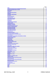
TABLE OF CONTENTSJ
INTRODUCTION
MODEL
..................................................................................................................................................................
3
IDENTIFICATION
UNPACKING
VENTILATION
INSTALLING
.............................................................................................................................................
4
AND HANDLING
.............................................................................................................................
5-6
REQUIREMENTS
ANTI-TIP
...............................................................................................................................
7
DEVICE .................................................................................................................................
8
CABINET PREPARATION .........................................................................................................................................
9-11
BACKGUARD
ELECTRICAL
HOOK-UP
INSTALLATION
.................................................................................................................................
12
/ GAS CONNECTIONS
.............................................................................................................
12-13
TO GAS SUPPLY ................................................................................................................................
13-I 4
INSTALLER FINAL CHECKLIST ...............................................................................................................................
15
WIRING
DIAGRAMISCHEMATIC
PRD3030 WIRING DIAGRAM
....................................................................................................................
16-19
...........................................................
16
PRD3030 SCHEMATIC .................................................................
17
PRD3630 WIRING DIAGRAM
18
...........................................................
PRD3630 SCHEMATIC .................................................................
WARRANTY
19
...................................................................................................................................................................
20-21
INTRODUCTION
Jenn-Air
Professional
of cooking
enjoyment
The large capacity
baking.
All models
IMPORTANT
chef. Ranges are available in 30"and
ovens of the Dual Fuel Range are self-cleaning
offer a minimum
of (4) 15,000 Btu/hr
and feature
sealed top burners.
36"widths.
convection
Dual-flow
simmer
and offer a low turn clown of 570-1,200 Btu/hr.
INSTALLATION
Professional
ranges must be installed
INFORMATION
Series is tested
in conjunction
capacity of this unit, particular
ensure it meets local building
units, cabinet
with a number of unique features certain to provide years
for the novice or experienced
electric
burners are provided,
The Jenn-Air
Ranges are designed
in accordance
with a suitable
attention
should
to UL Standard 858 and ANSI Z21.1. These
overhead
vent hood.
Due to the high heat
be paid to the hood and duct work installation
codes. To eliminate
risk of burns or fire by reaching
to
over heated surface
storage located above the surface units should be avoided.
Check local building
electrical connections,
codes for the proper method
and grounding
must comply
codes, the range should be installed in accordance
of range installation.
with all applicable
Local codes vary. Installation,
codes.
In the absence of local
with the National Fuel Gas Code ANSI Z223.1-1988
and National Electrical Code ANSI / NFPA 70-] 990. Be sure that the unit being installed is set up for the
kind of gas being used. The dual fuel range is shipped
Gas. It can be field-converted
for LP (propane)
with the unit. Refer to instructions
that the range is compatible
included
from the factory set and adjusted
by a qualified
with the conversion
with gas supply
technician
using the orifices
for Natural
provided
kit that is packed with the unit. Verify
at the installation
site before proceeding
further.
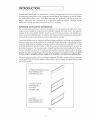
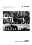
All ranges must be installed with one of three backguards (This piece must be ordered separately)
except model PRD3030, which is shipped standard with a 9" low backguard. See figure below for sizes
and model numbers.
22" High Shelf Backguard option
Model PRAD3022 (30")
Model PRAD3622 (36")
12" Lowback option
Model PRAD3612
9" Lowback
(30 models only)
Island Trim
Model PRAD3001 (30")
Model PRAD3601 (36")
Fig. I
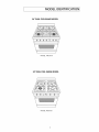
MODEL IDENTIFICATION I
36" DUAL FUEL RANGE MODEL
MODEL PRD3630
30" DUAL FUEL RANGE MODEL
MODEL PRD3030
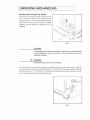
UNPACKING AND HANDLING
MOVING
1
AND PLACING THE RANGE
The ranges have shipping
weights varying
from 420
Ibs. to 630 Ibs. less approx. SO Ibs. after removal of
packing
material.
It is recommended
that the door,
grates, and front kick panel be removed to facilitate
handling.
handling.
This will reduce the weight
for ease of
Fig. 2
CAUTION:
Proper equipment
and adequate
manpower
must be used in moving the range
to avoid damage to the unit or the floor.
adjustable steel legs.
Z_
The unit is heavy and rests on
WARNING:
DO NOT lift range by the oven door handles!!
It may be necessary to remove the oven doors and knobs to pass through
doors and knobs removed, a 29-1/16"(PRD3630)/28-1/2"
removing
(PRD3030) wide opening
the door, a 31-1/2" (PRD3630) /30" (PRD3030) wide opening
carton and packing
material from the shipping
some doorways.
is required.
is required.
With the
Without
Remove the outer
base.
Left Rear
Shipping
i
Fig. 3
Screws
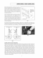
UNPACKING AND HANDLING
Remove the kick panel by removing
the top and pulling forward.
two screws at
The range is held to the
skid by two bolts in the front behind the kick panel,
(fig. 3) and two
L-brackets
located
Range Must
be Uniformly
Supported on
Braces
on the bottom
flange of the range back (fig. 3). After removing
the
bolts and brackets, the range
removed from the skid.
and
must be lifted
Due to the weight, a dolly with soft wheels should be
used
to
move
supported,
this
uniformly
unit.
The
weight
across the bottom
must
be
(fig. 4). To
remove the door, open the door and hold it all the
way open. Close the hinge latches (fig.5) and release
the door. The door can then be removed
lifting
and pulling
by gently
the door, with the hinges up and
Fig. 4
out of the frame (fig. 6).
The professional
tipped
range should
back and supported
be protected
be transported
by a dolly close to its final location.
The range can be
on the rear legs while the dolly is removed. The floor under the legs should
(Wood Strips, Carpet, Paneling, etc.) before pushing the unit back into position.
DOOR HINGEROLLERLEFT
DOOR HINGE ROLLERRIGHT
./
Fig. 6
Unloc_
Fig. 5
MOVING
AND PLACING THE RANGE
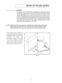
Electric and gas connections
should
page 9 & 10). The backguard
or island trim should also be installed
final position
be made before the range is slid into the cabinet
(refer to page 12). For proper performance,
achieve a flush fit of the range to adjoining
(front to back, and left to right across opening
countertops,
opening
(see
before the range is placed in its
the professional
range should
be level. To
it will be necessary to have level cabinets
of the range). After checking
and before sliding the range into place, measure the distance
the countertops
for level
from the floor to the top of the counter
work surface in the rear left and right corners. Adjust the corresponding
rear corner of the range to an
equal height of the counter, as the rear leveling legs are not accessible once the range is pushed into
place. Once the range is in place, the front leg levelers can be accessed to level the front of the range.
Replace the kick panel and oven door by reversing the procedure
that the two screws retaining
components
and wires (fig.2).
described
the kick panel are secure to prevent
previously.
accidental
It is important
access to live electrical
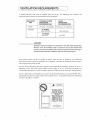
VENTILATION REQUIREMENTS
A suitable
minimum
exhaust
hood
blower capacity
must be installed
recommended
VENTILATION
UNIT
above
the range.
STANDARD COUNTER
INSTALLATION
RECOMMENDATIONS
HOOD
chart
indicates
the
ISLAND
INSTALLATION
RECOMMENDATIONS
(24" Deep x Unit Width)
BLOWER
The following
for hood ventilation.
(30" Deep x 36" at Bottom)
36" RANGE
600-1200 CFM
600-1200 CFM
30" RANGE
600 CFM
600 CFM
CAUTION:
Ventilation
hoods and blowers are designed
codes or inspectors
ducting.
codes and/or local agencies, before starting,
Consult local building
ensure that hood and duct installation
Hood blower
household
speeds
for use with single wall ducting.
However, some local building
should
be variable
air when maximum
ventilation
to reduce
may require
wall
to
will meet local requirements.
noise and loss of heated
is not required.
double
or air conditioned
Normally, the maximum
blower
speed is
only required when using the grill.
For best smoke elimination,
the lower edge of the hood should
be installed
a minimum
of 30" to a
maximum of 36" above the range cooking surface, (page 10 & 11). If the hood contains any
combustible
materials (i.e.a wood covering) it must be a minimum of 36" above the cooking surface.
Due to a high volume
of ventilation
particularly important for tightly
contractor should be consulted.
air, a source of outside
replacement
sealed and insulated homes.
WARNONG
THiS
PRODUCT
SHOULD
NOT
BE INSTALLED
BELOW A
VENTILATION
TYPE HOOD
SYSTEM
THAT
DIRECTS
AiR
IN
A
DOWNWARD
DIRECTION
(SEE FIGURE)
THESE
SYSTEMS
MAY CAUSE
IGNITION
AND COMBUSTION
PROBLEMS
air is recommended.
A reputable
WITH
THE
BURNERS
RESULTING
PI_RGONAL
INJURY
AND
GAS
IN
MAY
AFFECT
THE COOKING
PERFORMANCE
OF THE UNIT.
_o_
FIGURE_AY _0__CC_R_T_y
R_R_s_r YOUR
RANGE
ORC00K_01';
This is
heating and ventilating
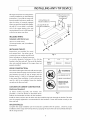
INSTALLING ANTI-TIP DEVICE
All ranges must have an antFtip
correctly
device
(2) Wood Screws into
Back Wall (ALL
Installations)
installed as per the following
instructions.
If you pull the range out
(2)Small Holes for
Wood Installations
from the wall for any reason, make sure
that the device
is properly
engaged
when you push the range back against
the wall.
(2) Large Holes for
Concrete Installations
If it is not, there is a possible
risk of the
range
tipping
over
BACK
WALL
and
causing injury if you or a child stand, sit
or lean on an open oven door.
INCLUDED
Included
PARTS:
with
(4) #10 x 2"wood
this kit are:
screws,
(1) AntFtip bracket, and (1)Installation
Instructions.
INSTALLING THE KIT:
Instructions
are provided
and cement
floors.
construction
may require
lation techniques
for wood
Any other type of
Fig. 7
special instal-
as deemed
necessary
to provide
adequate
fastening
of the Anti-tip
bracket to the floor and wall. The use of this bracket
does not preclude
tipping
of the range when
properly
installed.
WOOD
CONSTRUCTION:
not
A=
I/4"
Model
Series
5/8"
PRD3030
Place the bracket against the back wall, into the right
/_
PRD3630
WARNING
rear corner where the range is to be located. Leave a
gap between
the wall
(or side of range) and the
bracket (see fig.7). Drill (2) 1/8"diameter
= ALL
RANGES
in the centerofthe
small holes. A nail or awl may be
used if a drill is not available. Fasten the bracket
i INJURY
® INSTALL
securely to the floor and wall.
BRACKET
INSIDE
CONCRETE OR CEMENT CONSTRUCTION:
Hardware
(2) sleeve
CAN
TiP
pilot holes
COULD
RESULT
ANTI-TIP
PACKED
OVEN
• SEE INSTRUCTIONS
Required:
anchors,
lag
bolts,
and
washers
(not
provided).
Locate the bracket as described above.
Drill the recommended
size holes for the hardware.
Fig. 8
Install the sleeve anchors into the holes and then install the lag bolts through
must be properly
floor and wall.
tightened
as recommended
for the hardware.
the bracket.The
bolts
Fasten the bracket securely to the
ONCE INSTALLED:
Complete the range installation
per the instructions
provided with the product.
Check for proper
installation of the range and Anti-tip device by grasping the back of the unit and carefully attempt to
tilt the range forward.
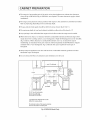
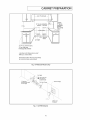
CABINET PREPARATION
1) The range is a free standing
unit. If the unit is to be placed adjacent to cabinets, the clearances
shown in fig.9 (PRD3630) & fig. 10 (PRD3030) are required.
installations.
The same clearances apply to island
2) The range can be placed in various positions with respect to the cabinet front, with the front either
flush or projecting, depending on the countertop depth.
3) The gas and electrical
supply should be within
the zones shown (fig.9, 10 & 11).
4) The maximum
depth of over head cabinets
S) Any openings
in the wall behind the range and in the floor under the range must be sealed.
6) When there is less than a 12"clearance
range (above the cooking
(fig. 12-Standard).
between combustible
surface), a Low backguard
(fig. 12-Island ). When clearance
installed
installed on either side of the hood is 13"
to combustible
material
These parts must be ordered
standard with a 9" Low backguard).
material and the back edge of the
or High Shelf backguard
must be installed,
is over 12'[ an island trim may be
separately
(model PRD3030 is shipped
Fig. 12 indicates the space required for each type of
backguard.
7) Always keep the appliance
flammable
area clear and free from combustible
materials, gasoline and other
vapors and liquids.
8) Do not obstruct
the flow of combustion
and ventilation
air to the unit.
0 0/
LM
.
1
12 rain.to combustible-
18"Min.
__I 4"
material
eachside
O
3-1/2"electrical
supply
gasSupply
l
35-3/8"max.forlevelcounter,
36-3/4"max.with range
levelinglegsfullyextended
A Asdefinedinthe"Nati0nalFuelGasCode"
(ANSIZ223.1,lastestedition).
Thehorizontalsurfaces
0fthe rangetop (c00kt0p)
trimmustnot bebelowc0untert0plevel.
Fig. 9 PRD3630
Model
Only
CAUTION:
36"rain,to
combustible
material
fromcookng
surface
CABINET PREPARATION
35-3/4"max,forlevelcounter,
37"max,with range
levelinglegsfullyextended
A Asdefined
in the"National
FuelGas
Code"
(ANSI
Z223,%
lastest
edition),
Thehorizontalsurfaces
of therangetop (cooktop)
trimmustnot bebelowcountertoplevel.
Fig. 10 PRD3030
Model
Only
Manual
Shut-Off
Valve
mustbe
Easily
Accessible
2"Maximum
Protrusionfrom Wall
for GasSupply
Electrical
Supply
FlexLinetoRange,.
:
_
!
"'i"-.
""--..•.
NEMA14-SO
Receptacle
Fig. 11 All PRD Models
10
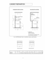
[CABINET PREPARATION
STANDARD
ISLAND INSTALLATION:
INSTALLATION:
12"Min.to
Combustibles/X
without backguard
High Shelf Backguard
36"Min.to
Combustibles
_.
(bim."A")
A
I
_/Island
Low Backguard
(Dim."B")
I
Trim
_
0" Clearance
D
_E_IIIIIIIIIIIIIIIIIIII
_"
_i_
_F
A Asdefined in the
"National FuelGasCode"
(ANSIZ223.1,Latest Edition).
Thehorizontal surfacesof the rangetop (cooktop)
trim must not be below countertop level,
Fig. 12 All PRD Models
0 0 0
Product
/ installation
Clearance
O0
00oa
--K--
Specifications
0
O0
u
--K--
PRD3630 Model
PRD3030 Model
A
B
¢
F
G
PRD3630
22"
12"
2"
35-1/2"min.-37"max.
D
30-1/4"
44-1/2"
28-1/4"
1-5/16"
25"
27-3/8"
35-7/8"
PRD3030
22"
9"
2"
35-3/4"min.-37"max.
28-3/16"
43-7/8"
27-3/8"
1-5/16"
24-3/16"
26-3/4"
29-7/8"
11
E
H
I
J
K
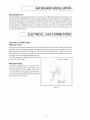
BACKGUARD INSTALLATION
BACKGUARD
KITS:
Model PRD3030 is shipped standard with a 9" Low backguard.
the Low Back for Model PRD3630 must be ordered
the High Shelf backguard,
backguard.
All backguards
into the cabinet.
combustibles
backguard
Low backguard
separately.
Specific instructions
for installation
or Island Trim Backguard can be found packaged
or island trims must be installed
A backguard
High Shelf backguards, Island Trims and
must be installed
on
the range before the unit is pushed
when there is less than a 12" clearance
and the back of the range (above the cooking
of
with the
between
surface). See fig. 12. Refer to page
3 for
model numbers.
ELECTRICAL / GAS CONNECTIONS
ELECTRICAL CONNECTIONS
PRD3630
model
Always disconnect
appliance.
electric supply cord from the wall outlet or service disconnect
Observe all governing
codes and ordinances
when grounding,
National Electrical Code ANSI / NFPA No. 70-I 990. The electrical
(plus ground)
unit.The
receptacle
must be a NEMA 14-50 device
with the
should be located within
the
area shown in fig.9 page 9.
_--.
PRD3030
The electrical
wire
Electrical Supply
j
MODEL
supply
(plus ground),
power receptacle
must be a 120/240
60 Hz, 30 AMP circuit.
volt, 3
The
must be a NEMA 14-50 device
to accept the four prong plug supplied
unit. The receptacle
with the
should be located within the
area shown in fig. 10, page 10.
\
_-..
NEMA 14-50
Receptacle
Fig. 13
12
this
supply must be a 120/240 volt, 3 wire
60 Hz single phase, S0 AMP circuit. The power receptacle
to accept the four prong plug supplied
before servicing
in absence of which,observe
ELECTRICAL / GAS CONNECTIONS
RECOMMENDED
This appliance
is factory equipped
must be plugged
volt circuit.
obligation
GROUNDING
METHOD
with a power supply cord with a four-prong
into a mating grounding,
If the circuit
of the installer
type receptacle, connected
does not have a grounding
to have the existing
type receptacle,
receptacle
grounding
to a correctly
changed
plug.
polarized
it is the responsibility
to a properly
It
120/240
grounded
and
and
polarized receptacle in accordance with all applicable local codes and ordinances by a qualified
electrician.
In the absence of local codes and ordinances, the receptacle replacement shall be in
accordance with the National Electrical Code.
THE FOURTH PRONG (ROUND GROUNDING PIN) SHOULD NOT, UNDER ANY
CIRCUMSTANCES, BE CUT OR REMOVED.
GAS REQUIREMENTS
Verify the type of gas supplied
to the location.
adjusted for natural gas. It can be field-converted
with the conversion
NATURAL
The range is shipped
from
the factory
for LP (propane) gas. Refer to instructions
set up and
included
kit that is packed with the unit.
GAS
ll Connection:
1/2" N.P.T.Minimum
5/8"dia.flex
line.
ll Supply Pressure: 6"to
I/2" N.P.T.Minimum
5/8 dia.flex
line.
m Supply Pressure: 11"to 14"W.C.
14"W.C.
LPGAS
m Connection:
A regulator
is required at the LP source to provide a maximum
of 14"W.C.to
lNOOK-UPTO GAS SUPPLY
the range regulator.
J
HOOK-UP
A manual valve must be installed
the purpose of shutting
offthe
external to the appliance,
unit. Make sure the gas supply is turned
The gas supply connections
codes or ordinances.
in an accessible location from the front for
gas supply. The supply line must not protrude
offat
the wall valve before connecting
should be made by a qualified
technician
In the absence of a local code, the installation
Gas Code ANSI 223.1-1988, latest edition.
13
beyond the back of the
the appliance.
and in accordance
must conform
with local
to the National Fuel
HOOK-UP TO GAS SUPPLY
CAUTION:
The appliance
must be isolated
from the building's
gas supply piping system
by closing its individual manual shut-off valve during any pressure testing of
the gas supply piping system at test pressures equal to or less than I/2 psig
(3.SkPa.). The appliance and its individual
shut-off
valve must be disconnected
from the gas supply piping system during any pressure testing of the system at
the test pressures in excess of I/2 psig (3.SkPa.)." When checking the manifold
gas pressure, the inlet pressure to the regulator
(Water Column) for natural
gas or 12.0"for
should
be at least 7.0" W.C.
LP.
NOTE: The flex line for the gas supply must be metal and be approved by an approved
certifying agency (AGA, CGA, or UL). Never use a hose made of rubber or other
synthetic material, as the heat may cause the hose to melt and develop leaks.
When hooking
up the gas supply from
range rear hard pipe to wall hard pipe,
installation length of flex line between
range/wall
hard
accommodate
from
wall
purposes.
range
piping
being
for cleaning
must
pulled
or servicing
| Manual
Valve must be
When range is pulled from
Easily Accessible
wall, no strain should occur at range or
WALL
wall hard pipe connections
Hard Pipe
Connection
(fig. 14).
Hard Pipe
1/2" N PT
Fig. 14
14
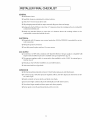
[INSTALLER FINAL CHECKLIST
GENERAL
FI Placement of unit.
FI Specified
clearance maintained
to cabinet surfaces.
r] Unit Level - front to back, side to side.
FI All packaging
material and tie straps removed, drip pans clean and empty.
FI Backguard attached if there is less than 12" clearance above the cooking
construction
behind unit.
FI Island trim attached if there is more than
combustible construction
behind the unit.
12" clearance
surface to combustibl
above the cooking
surface to the
ELECTRICAL
r] Receptacle with 50 ampere
cord connection.
r] Adequate
ground
over-current
protection
(30A for PRD3030) is provided
for service
connection.
r] Front kick panel in place and two (2) screws secure.
GAS SUPPLY
r] Connection: 1/2 NPT with a minimum 5/8" diameter flex line. Site gas supply is compatible
range model, & sufficient pressure is available (see gas requirements pg. 13).
FI The pressure regulator
10.0 W.C. for LR
FI Manual gas shut-offvalve
which is connected
installed
to the manifold
with
is set for 5.0 W.C. for natural gas or
in an accessible location.
FI Unit tested and free of gas leaks.
OPERATION
F1 All internal
packing
materials removed.
Check below grate, pans and drip drawers.
F1 If used on LP gas, verify that pressure regulator, orifices, and valve bypass jets have been set for
use with LP gas.
F1 Bezels centered
on burner knobs and knobs turn freely.
FI Each burner lights satisfactorily,
both individually
and with other burners.
FI Oven door hinges seated and door opens and closes properly.
FI Burner grates correctly
positioned,
level, and do not rock.
15
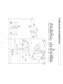
PRD3030 WIRING DIAGRAM
LF
16
I
HWR
]s]
l
S_RFAEE_
L_
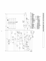
_
NOTES:
AS = AIR_ZTO_
IKI = EdT_R@_ ILE_NI
IK_ = _
BAKEELE_NT
IL_F
ISIAT= _
TFER_AT
- OJ]SE_ RISE
RR
AT ND Y
IL ._ A
IR
= _OIL
[_
= EIINVEETI_
B_E
[L
= O-EAN
CH
= EOg_EETION
MOIOR
ITNILI=UC_TTNI
INDI_IOR
@R
= 111VI_ REL_
H_E = HI_ l_F OJTOUI
I_N - IGNIT_R
K[
= O__4N_L_Y _Ol
K3
= LATO_ELOSERELAY
K4
= LAI04_o_ ___
LF
= L@7 FR3NI
L£
= LAI04_TOR,10JR
LR
= LEFTREAR
LT
= LI_dT
N[
_ NO_4ALLY
[LOSEI
NO
= NO_4ALLY
OPEN
v
E_K
£41
VAL
sw_
]
]$3
0
PLSR = _
0
I
m
PdLS_
m
R_IG_I = _IGNITION
BLUR
No]STk_
S_
I
S_
= Gg_ S_
(I_:>IK>_<_II>[L
)
= @ITGH
T_XTAT MAIN'0_{111_
_ _([_
12i V
__
NO,[_
IN [LEANl_tY
L]£K = U]L<Y_l
T-STA[ [I_EO < ZSTF
(L_[_ _
TSI
TS2
TS3
T_4
IS5
I_
III_I<II(_IR
IN _N)
= TE_INALST_I_LI
- _IN F{]_ SdFfLY
= TE_IN_LSI!_I_
L_
- _IN F_]_9_]FfLY
= TE_INALST_IF_b]_L
= TE_INALST_IF
_I_L TIPA}_A
= TE_INALSI_I_L2
LIVE-T_
= TE_IN_LSI_I_
IN[!R=LA_
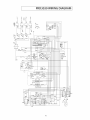
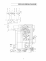
PRD3630 WIRING DIAGRAM
_8
(I)
(_)
7
L
_fzfr_
_ mmB__imJ_
6" _ #lFr_
(_)
=
1Q
18
T_L
(I)
L
_s]
!20 V
240
LF
LR
30'HWR
AIRSWITCH
BAKE
BZ]WE_]_3STAT
- CLI]SE
EN RISE
&E_ER _T[R
_ROIL
RF
= RIGHTFRONT
CI]qVECTIONBA!_
RIS
: R_IKINTERLOEK
S_[PEH
O_IERI:_II_
RR
= RIGHTRE&R
OFAN
SEL = OVEN
SELEETQR
ILIBWECTI[N
_BTER
(OFF.BK[BK BREL)
REAR
SW
: S_ITEH'
' '
R]SITI_ SWITCH T-STAT: OVEN
THERMRSP&T
Q_EAN_ELAYDPDT
[-3 [YCLING[ONTAIT
LAT_OZ_R&AY 3POT
4-5 [&MUPER&TEDLATO_B_EN_AYCPBT
OPENIN [LE&N
LE_FRB_
POSITION& OFF
LAI'O_,
_
0-7_PEN> 550_F
LEFf@FAR
(LBEKSDDDR)
LI[_T
TS[
= TERMINAL
STRIPL[
[YEN& RIVING
- MAINPORER
SUPPLY
II_AROSEL[5_
TS2
= TERMINAL
STRIPL2
CL[]SB]&[]RIVING
- M&INPOWER
SUPPLY
I_AEIS[PBI
TS3
= TERMINAL
STRIPNEUTRAL
F_TW[RERELAY
M&INPOWERSUPPLY
HI_II_Q]IlZiT
TS4 = TERNIN&L
STRIP
IBNIIER
NEUTR&L
TOP&RE&
I'I]II_P[EITZ[_SWlTCH
TS5
= TERMIN&L
STRIPL2
50%PLLSER
LIVE-TOP&RE&
TS_ : TERMIN&L
STRIP
:X)
_J
0
I
m
_B
TS3
m
\ S_I_CH
IS2
L
WARRANTY 1
FULL ONE YEAR WARRANTY - PARTSAND LABOR
For one (I) year from the original
retail purchase date, any part which fails in normal home use will be
repaired or replaced free of charge.
Limited Warranties
- Parts Only
Second Year - After the first year from the original
purchase date, parts which fail in normal home use
will be repaired or replaced free of charge for the part itself, with the owner
including
labor, mileage and transportation,
Third Through
trip charge and diagnostic
Fifth Year - From the original
purchase
paying all other costs,
charge, if required.
date, parts listed below which
fail in normal
home use will be repaired or replaced free of charge for the part itself, with the owner paying all other
costs, including
labor, mileage and transportation,
[] Electronic
trip charge and diagnostic
charge, if required.
Controls
[] Electric Heating
Elements: Broil and bake elements
on gas and electric cooking
appliances.
[] Sealed Gas Burners
CANADIAN
RESIDENTS
The above warranties
appropriate
brought
only cover an appliance
test agencies for compliance
installed
in Canada that has been certified
or listed by
to a National Standard of Canada unless the appliance
was
into Canada due to transfer of residence from the United States to Canada.
Limited Warranty
Outside the United States and Canada - Parts Only
For two (2) years from the date of original
retail purchase, any part which fails in normal home use will
be repaired
for the part itself, with
including
or replaced
free of charge
labor, mileage and transportation,
the owner
trip charge and diagnostic
paying
all other
costs,
charge, if required.
The specific warranties expressed above are the ONLY warranties provided by the manufacturer.
legal rights, and you may also have other rights which vary from state to state.
These warranties
give you specific
WHAT IS NOT COVERED BY THESE WARRANTIES:
1. Conditions
and damages
a. Improper
installation,
resulting
from any of the following:
delivery, or maintenance.
b. Any repair, modification,
authorized servicer.
alteration,
or adjustment
c. Misuse, abuse, accidents, or unreasonable
not authorized
by the manufacturer
or an
use.
d. Incorrect electric current, voltage, or supply.
e. Improper
setting of any control.
2 Warranties are void if the original
readily determined.
serial numbers
have been removed, altered, or cannot
3. Light bulbs.
4. Products
purchased for commercial
or industrial
use.
5. The cost of service or service call to:
a. Correct installation
errors.
b. Instruct the user on the proper use of the product.
c. Transport
the appliance
to the servicer.
2O
be
[WARRANTY
6. Consequential or incidental damages sustained by any person as a result of any breach of these
warranties. Some states do not allow the exclusion or limitation of consequential or incidental
damages, so the above exclusion may not apply.
IF YOU NEED SERVICE
[] Call the dealer from whom your appliance was purchased or call Maytag Services sM,Jenn-Air
Customer Assistance at 1-800-JENNAIR (1-800-536-6247) to locate an authorized servicer.
[] Be sure to retain proof of purchase to verify warranty status. Refer to WARRANTY for further
information on owner's responsibilities for warranty service.
[] If the dealer or service company cannot resolve the problem, write to Maytag Servkes% Attn:
CAIR_ Center, RO. Box 2370, Cleveland,TN 37320-2370, or call 1-800-JENNAIR (1-800-536-6247).
U.S. customers
using TTY for deaf, hearing impaired
NOTE:When writing
or speech impaired,
or calling about a service problem,
a. Your name, address and telephone
call 1-800-688-2080.
please include the following
information:
number;
b. Model number and serial number;
c. Name and address of your dealer or servicer;
d. A clear description
of the problem
you are having;
e. Proof of purchase (sales receipt).
[] User's guides, service manuals
Jenn-Air Customer Assistance.
1-800-JENNAIR (1-800-536-6247)
Mon.-
and parts information
1-800-688-2080
Fri.,8 am - 8 pm Eastern Time
are available
from
Services%
(U.S.TTY for hearing or speech impaired)
Intemet:
www.jennaincom
Maytag Services _m
Attn: CAIR ® Center, RO. Box 2370, Cleveland, TN 37320-2370
21
Maytag
22
Before you begin, read these instructions completely
/h
and carefully.
WARNING
If the information
tn these instructions is not followed exactly, firet explosion
or
production of carbon monoxide may result_causing property damage, personal injury or
loss of life.
This conversion kit must be installed bya qualified service agency in accordance with the
manufacturer's instructions. All applicable codes and requirements of the authority
having jurisdiction must be followed. The qualified service agency is responsible for the
proper Installation of this kit. The installation is not prdper and complete until the
operation of the converted appliance is checked as specified in the manufacturer's
instructions supplied with the kit.
PARTS INCLUDED
TOOLS NEEDED
,_ng]e Flow Burner Orifice (4)
1/8" Flat-blade Screwdriver
Phillips Screwdriver
_5'*uatFlow Main Burner Orifice (2)
Adjustable Wrench
25/32" Deep Socket
Dual Flow Simmer Burner Orifice (2)
I_ngie
_
Flow Bypass Jet (4)
,,
7mm Nut Driver
1/2" Deep Socket
T-IS Torx Screw Driver
Manometer
Dual Flow Main Bypass Jet (i)
7ram Box or Open End Wrench
Dual Flow Simmer BypassJet (2)
Ratchet with 1-1/16" Hex Deep Socket
onversi'on Sticker (1)
_t'_lve Stem C-Clip (4)
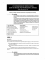
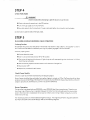
STEP 1
GAS SUPPLY
Measure the incoming gas pressure to the regulator.
With the installation of this conversion kit, the range should operate on LP gas at 10" of water column pressure.
• The pressure regulator must be connected
series with the supply line.
in series with the manifold of the range and must remain in
• When checking the regulator, the inlet pressure must be at least 1" greater than the regulator
se=ing.
output
- The regulator is set for 10" of water column pressure; the inlet pressure must be at least 11".
For proper operation, the maximum inlet pressure to the regulator must be no more than 14;' of water column
pressure.
z_
WARNING:
Beforeproceeding with the conversion, shut off gas supply to the appfiance prior
to disconnecting the electricaI power. Thisis to prevent release of any g_s during
the conversion.
IMPORTANT:
Disconnect
during
the range
ony pressure
the range
from
and the individual
testing
the gas supply
valve to the range
during
piping
NOTE: Gas conversion should
system
any pressure
pressures equal to or less than
Connection:
shut-off
by closing
testing
greater
than
the individual
of the gas supply
system
1/2 psig. isolate
manual
piping
system
shut-off
at test
7/2 psig.
I/2" N.P.T. - minimum
be done before
valve from the gas supply piping
of that system at test pressures
5/8"
pushing
dia. metal
the range
flex line.
into the cabinet.
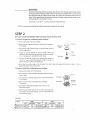
STEP 2
REPLACE COOK'I-OP'BURNER ORIFICES AND VALVE BYPASS JETS
To replace single flow cooktop
1, Remove the grates
2. Remove burner
burner
orifices:
from the cooktop.
caps and brass port rings (refer to diagram
BurnerHead
to the right).
0"
(Brass)
3. Unscrew
the brass venturis
25i32"deep
4. Locate
surface
6 Verify
orifices
using
that
the
orifice
a 7ram
from
falling
2. Remove
to the
a
burner
the
base).
bases,
B_merBase .
inside
socket
or
the socket
to
_l
Vemuri
Declr0de
out,
kit match
the
chart
sizes and
replace
the
burner
orifices.
Do
at this time.
To replace dual flow cooktop
1. Remove the grates from
below
conventional
tape
sizes in the
the burners
holder
the burner
of sticky
the loose orifice
jet
the hole in the burner
to remove
Use a piece
r_a_semble
in the
(Iook through
the orifices
nut driver,
prevent
bases using
l
burner
It is not necessary
S, Unscrew
the burner
socket•
the
cooktop
from
Bume_Cap
I
burner
orifices:
the ¢ooktop.
caps and flame
spreader
(refer to diagram
.,BUrner
(_p
right).
FlameSl_r,,d,,. _£
3. Unscrew simmer
or nut diriver.
orifices
using
the main orifice
adjustable
&Verify
and
plate using a phillips
using
a 7ram wrench
" MainOnfice
or an
wrench.
that
the orifice
replace
burners
socket
"_/
4. Remove main orifice cover
screwdriver.
5. Unscrew
a 7ram conventional
sizes in the kit match
the burner
orifices.
Do not
the chart sizes
reassemble
the
at this time.
LP GAS
VALVE
,/ tSingle
LOW
MAIN
SIZE
Flow
,,_uat Flow
MARKINC
RATE
t,07mm
107
12K Btu/hr
1.09ram
109
1SK Btu/hr
N/A
J, SIZE
,_'_7mm
RATE
MARKING
NiA
2,600 Btuihr
37
4,200 Btu/hr'
not
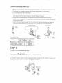
TOREPLACE
THEVALVEBYPASS
JETS:
i. Remove
thecontrol knobs from the valve shafts
2. Remove the two
3. Remove the four
screws
5. Disconnect
that attach valve panel to thermostat
mounting
4. Put] the paneI forward
screws from
terminals
careful
not to allow
6, Remove the C-ctips
the corners
bracket
(located
behind
thermostat
knob),
of the valve par_e! (T-15 Torx Screw).
over the vaJve stems.
the wiring
panel, being
and thermostat.
that retain
at the light
switch.
Unsnap
the lenses to fall from
the valve switches
the indicator
and slide the switches
7. Locate the valve bypass jets [n the vatve bodies.
and remove from valves,
Using
a flat blade
8. Verify that the vaIve bypass jet sizes in the kit match the chart
Screw the jet into the valve body until fully seated.
SINGLE
lights
from the back of the valve
the face of the panet.
off of the valve shafts,
screwdriver,
sizes and replace
Do not re-install
unscrew
the bypass iets
the valve bypass jets.
the vatve panel at thFs time,
FLOW
DUAL
FLOW
BYPASS JET
VALVE
SIMMER
JET
VALVE ORIFICE
MAIN
BYPASS JET
BYPASS JET
VALVE
LP
0.46mm
46
RATE
2,600 Btuihr
Dual Flow Main
0.53mm
53
4,200 Btu!hr
Dual Flow Simmer
0.34mm
34
1,000 Btu!hr
SIZE
*.I "Singte F]ow
..........
MARKING
i
STEP 3
CONVERT THE PRESSURE REGULATOR
Z_
WARNING
Do not remove
To access the regulator,
Natural
remove
gas to LP gas, reverse
the pressure
regulator
the kick panel, located
from the range.
below
the set screw in the regulator.
the range
See diagram.
Burner Cap
door.
To convert
the regulator
from
STEP 4
CHECK FOR LEAKS
,/'fX, WARNING
Check for leaks before attempting
to light
the burners
or use the oven.
• Check to be sure all controls are in the OFF position,
III Turn on the gas supply
In Use a leak detector
at the shut-off
at all connections.
valve.
If a leak is detected,
tighten
the connection
and test again,
DO NOT USE A FLAME TO CHECK FOR GAS LEAKS.
STEP 5
RE-ASSEMBLE SURFACE BURNERS, CHECK OPERATION
Cooktop
Section
Re-assemble
the burners
secure valve switches.
Check for proper
• Connect
and valve panet
in the reverse order
shown
Make sure the brass port rings are properly
in Step 2 above.
engaged
Use supplied
in the burner
"C" clips to
bases.
ignition:
electrical
power.
• Push in one control
II The igniter
knob
and turn 90_ to"Hl"position.
will spark and the burner
that at} burners
wiJ[ Iight; the igniter
will cease sparking
when
the burner
is lit, (Note
will spark.)
•
The first test may require
•
T[Jrn knob to"OFF"
•
Repeat
the procedure
some time while
air is flushed
out of the gas Iine.
for each burner,
Check Flame Quality
Check for proper
Burner
flames
excessive
burner
should
flame
characteristics
be blue and stable.
noise or exhibit
usage (i,e. gas pressure,
lifting
(see diagram,
Some yellow
page 5).
tipping
is normal
on LP Gas.The
of the flame from the burner. Due to differences
cleanliness, etc.), burners
may perform
flame
should
in gas characteristics
not have
and burner
differently.
Burner Operation
This gas range
have three
detent.
is equipped
rings off[ames
with
when
When the knob is rotated
small inner burner
The remaining
the"HtGH"
one (PRD3030)
in operation
or two
between
past the low position
(PRD3630)dual
the"HIGH"control
detent,
flow simmer
burners.
knob setting
only one ring of flame
These burners
and the tow position
is present
around
_he
cap,
burners
are of the traditional
and "LOW" control
knob settings,
single flow design,
The single ring of flame is regulated
Refer to the following
diagrams,
between
Burner Adjustment
i
There is no air shutter
adjustment,
etc, on this burner.
DUAL FLOW
SINGLE FLOW
Cap
Burner Cap
Simmer
Flame
High to Low
Flame
STEP 6
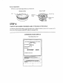
COMPLETE AND ADHERE CONVERSION LABEL TO THE REAR OF THE RANGE
Complete the required information
Rating Label. The Conversion
on the Conversion Label. Adhere the label to the rear of the range next to
Label MUST reflect the change of fuel.
CONVERSION STICKER SAMPLES
From Natural
Gas to LP
"11-II$
CONVEI_ION _TING !,,AI_L I_L&,T_$TO THE FOLLOWING
JENI_AIR MODEL_,:
SUPPLYPRE.&SU
RE_MINIMUM 1_*W,C,
MAXIMUM 14"W.C
MANIFOLD PI_$SURE -I _'w,c.
INPttT I_T1NGS.
_
COI_ON
_NG_I_FLOW_URNE,_S
DUAL FLOWBURNrfl_S
* 12,0O0STU/N_
- 1$_00 _t%l,'14R
)_T FEAST.92093-03
I
114tS_PIJaNCE HASIIEEt_¢ONV'_IZD ON I
FROMNATURA!.GASTOLP GASWITH CONVERSIONKIT
R_ NO,g2093_03
]
WNO ACCEPTSp,,£.&_O
F_4B_
L'T'_T'Y
._OR_
CONV'EF_ON
I
I
¢Of_ECTN_S OF
JENN-AIR
1-800-JENNAIR (1-800-536-6247)
1-800-688-2080
(U.S.TTY for hearing or speech impaired)
Mon.- Fri., 8 am - 8 pm Eastern Time
1-800-688-2080
(ATS Etats-Unis pour les malentendants
du lundi au vendredi,
1-800-688-2080
Internet:
et les handicap6s
de 8 h O0 _ 20 h 00, heure de I'est
(TTY para personas con problemas
auditivos
De lunes a viernes de 8 am a 8 pm hora del este
www.jennaincom
Internet:
www.jennair.com
o impedimentos
Internet:
del habla)
www.jennair.com
Maytag Services _"
Attn: CAIR _ Center, P.O.Box 2370, Cleveland,TN
de la parole)
37320-2370