1
User Manual for CoolSNAPcf, CoolSNAPcf2, CoolSNAPEZ,
and CoolSNAPES2 Systems
© Copyright 2005
Roper Scientific, Inc.
3440 East Britannia Drive
Tucson, Arizona 85706
Tel: 800.874.9789/520.889.9933
Fax: 520.295.0299
All rights reserved. No part of this publication may be reproduced by any means without the written
permission of Roper Scientific, Inc.
Printed in the United States of America.
CoolSNAP is a trademark and Photometrics, PVCAM, and Roper Scientific are registered trademarks of
Roper Scientific, Inc.
Mac, Macintosh, Mac OS, and Panther are trademarks of Apple Computer, Inc., registered in the U.S. and
other countries.
Pentium is a registered trademark of Intel Corporation. Xeon is a trademark of Intel Corporation.
Windows is a registered trademark of Microsoft Corporation.
Other brand and product names are the trademarks or registered trademarks of their respective owners and
manufacturers.
The information in this publication is believed to be accurate as of the publication release date. However,
Roper Scientific does not assume any responsibility for any consequences including any damages resulting
from the use thereof. The information contained herein is subject to change without notice. Revision of this
publication may be issued to incorporate such change.
LIMITED WARRANTY — Photometrics Analytical Instrumentation
Photometrics, a division of Roper Scientific, Inc. (“Photometrics,” us,” “we,” “our”) makes the following
limited warranties. These limited warranties extend to the original purchaser (“You”, “you”, "Your", "your")
only and no other purchaser or transferee. We have complete control over all warranties and may alter or
terminate any or all warranties at any time we deem necessary.
Basic Limited One (1) Year Warranty
Photometrics warrants this product against substantial defects in materials and/or workmanship for a period
of up to one (1) year after shipment. During this period, Photometrics will repair the product or, at its sole
option, repair or replace any defective part without charge to you. You must deliver the entire product to the
Photometrics factory or, at our option, to a factory-authorized service center. You are responsible for the
shipping costs to return the product. International customers should contact their local Photometrics
authorized representative/distributor for repair information and assistance, or visit our technical support
page at www.photomet.com.
Limited One (1) Year Warranty on Refurbished or Discontinued Products
Photometrics warrants, with the exception of the CCD imaging device (which carries NO WARRANTIES
EXPRESS OR IMPLIED), this product against defects in materials or workmanship for a period of up to one
(1) year after shipment. During this period, Photometrics will repair or replace, at its sole option, any defective
parts, without charge to you. You must deliver the entire product to the Photometrics factory or, at our option,
a factory-authorized service center. You are responsible for the shipping costs to return the product to
Photometrics. International customers should contact their local Photometrics representative/distributor for
repair information and assistance or visit our technical support page at www.photomet.com.
Normal Wear Item Disclaimer
Photometrics does not warrant certain items against defect due to normal wear and tear. These items include
internal and external shutters, cables, and connectors. These items carry no warranty, expressed or implied.
Software Limited Warranty
Photometrics warrants all of our manufactured software discs to be free from substantial defects in materials
and / or workmanship under normal use for a period of one (1) year from shipment. Photometrics does not
warrant that the function of the software will meet your requirements or that operation will be uninterrupted
or error free. You assume responsibility for selecting the software to achieve your intended results and for the
use and results obtained from the software. In addition, during the one (1) year limited warranty, the original
purchaser is entitled to receive free version upgrades. Version upgrades supplied free of charge will be in the
form of a download from the Internet. Those customers who do not have access to the Internet may obtain the
version upgrades on a CD-ROM from our factory for an incidental shipping and handling charge. See Item 12
in the following section of this warranty ("Your Responsibility") for more information.
Owner's Manual and Troubleshooting
You should read the owner’s manual thoroughly before operating this product. In the unlikely event that you
should encounter difficulty operating this product, the owner’s manual should be consulted before contacting
the Photometrics technical support staff or authorized service representative for assistance. If you have
consulted the owner's manual and the problem still persists, please contact the Photometrics technical support
staff or our authorized service representative. See Item 12 in the following section of this warranty ("Your
Responsibility") for more information.
i
Your Responsibility
The above Limited Warranties are subject to the following terms and conditions:
1.
You must retain your bill of sale (invoice) and present it upon request for service and repairs or
provide other proof of purchase satisfactory to Photometrics.
2.
You must notify the Photometrics factory service center within (30) days after you have taken
delivery of a product or part that you believe to be defective. With the exception of customers who
claim a “technical issue” with the operation of the product or part, all invoices must be paid in full in
accordance with the terms of sale. Failure to pay invoices when due may result in the interruption
and/or cancellation of your one (1) year limited warranty and/or any other warranty, expressed or
implied.
3.
All warranty service must be made by the Photometrics factory or, at our option, an authorized
service center.
4.
Before products or parts can be returned for service you must contact the Photometrics factory and
receive a return authorization number (RMA). Products or parts returned for service without a return
authorization evidenced by an RMA will be sent back freight collect.
5.
These warranties are effective only if purchased from the Photometrics factory or one of our
authorized manufacturer's representatives or distributors.
6.
Unless specified in the original purchase agreement, Photometrics is not responsible for installation,
setup, or disassembly at the customer’s location.
7.
Warranties extend only to defects in materials or workmanship as limited above and do not extend to
any product or part which has:
•
been lost or discarded by you;
•
been damaged as a result of misuse, improper installation, faulty or inadequate maintenance or
failure to follow instructions furnished by us;
•
had serial numbers removed, altered, defaced, or rendered illegible;
•
been subjected to improper or unauthorized repair; or
•
been damaged due to fire, flood, radiation, or other “acts of God” or other contingencies beyond
the control of Photometrics.
8.
After the warranty period has expired, you may contact the Photometrics factory or a Photometricsauthorized representative for repair information and/or extended warranty plans.
9.
Physically damaged units or units that have been modified are not acceptable for repair in or out of
warranty and will be returned as received.
10. All warranties implied by state law or non-U.S. laws, including the implied warranties of
merchantability and fitness for a particular purpose, are expressly limited to the duration of the
limited warranties set forth above. With the exception of any warranties implied by state law or nonU.S. laws, as hereby limited, the forgoing warranty is exclusive and in lieu of all other warranties,
guarantees, agreements, and similar obligations of manufacturer or seller with respect to the repair or
replacement of any parts. In no event shall Photometrics’ liability exceed the cost of the repair or
replacement of the defective product or part.
11. This limited warranty gives you specific legal rights and you may also have other rights that may vary
from state to state and from country to country. Some states and countries do not allow limitations on
how long an implied warranty lasts, when an action may be brought, or the exclusion or limitation of
incidental or consequential damages, so the above provisions may not apply to you.
12. When contacting us for technical support or service assistance, please refer to the Photometrics factory
of purchase, contact your authorized Photometrics representative or reseller, or visit our technical
support page at www.photomet.com.
ii
U. S. Government Restricted Rights
The software and documentation are provided with Restricted Rights. Use, duplication, or disclosure by the
Government is subject to restrictions as set forth in subparagraph (c)(1)(ii) of the Rights in Technical Data and
Computer Software clause at DFARS 252.227-7013 or subparagraphs (c)(1) and (2) of the Commercial
Computer Software-Restricted Rights at 48 CFR 52.227-19, as applicable. Contractor/manufacturer is
Photometrics, 3440 East Britannia Drive, Tucson, AZ 85706.
This license is effective until terminated. It will terminate upon the conditions set forth above or if you fail to
comply with any term hereof. Upon termination, you agree that the software and accompanying materials,
and all copies thereof, will be destroyed. This agreement is governed by the laws of the State of Arizona. You
acknowledge that you have read this agreement, you understand it, you agree to be bound by its terms, and
that this is the complete and exclusive statement of the agreement between you and Photometrics regarding
the software.
iii
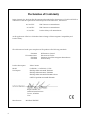
Declaration of Conformity
Roper Scientific, Inc. declares that the equipment described in this document is a CLASS A DEVICE in
conformance with the requirements of the European Council Directives, listed below:
89/336/EEC
EMC Directive & Amendments
93/68/EEC
EMC Directive & Amendments
73/23/EEC
Product Safety with Amendments
on the application of the laws of Member States relating to Electromagnetic Compatibility and
Product Safety.
This declaration is based upon compliance of the product to the following standards:
EN 55022
EN 61000-3 Series
EN 55024
EN 60950
RF Emissions Control
Harmonics & Flicker
Immunity from Electromagnetic Disturbances
Product Safety
Product Description:
Video Camera
Model:
CoolSNAPcf / CoolSNAPEZ , LVDS
Test Reports:
EMC Rpt 2K01-0122-003B- EN55022
EMC Rpt 2K00-0122-003C- EN55024
EMC Rpt 2K01-0122-003D-EN61000-3 Series
SAFETY Rpt 2K01-0122-003E-EN60950
Roper Scientific, Inc.
3440 East Britannia Drive
Tucson, AZ 85706
USA
Manufacturer:
iv
ROPER SCIENTIFIC
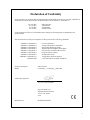
Declaration of Conformity
Roper Scientific, Inc. declares that the equipment described in this document is a CLASS A DEVICE in
conformance with the requirements of the European Council Directives, listed below:
89/336/EEC
92/31/EEC
93/68/EEC
73/23/EEC
EMC Directive
Amendment
Amendment
Product Safety
on the application of the laws of Member States relating to Electromagnetic Compatibility and
Product Safety.
This declaration is based upon compliance of the product to the following standards:
EN50082-1, EN60000-3-2
EN50082-1, EN60000-3-3
EN50082-1, EN61000-4-2
EN50082-1, EN61000-4-3
EN50082-1, EN61000-4-4
EN50082-1, EN61000-4-5
EN50082-1, EN61000-4-6
EN50082-1, EN61000-4-11
EN55022-1998
Current Harmonics
Voltage Fluctuations and Flicker
Electrostatic Discharge (ESD)
Radiated Electromagnetic Field (EMF)
Electrical Fast Transient/Burst (EFT)
Surge Immunity (Mains)
RF Injected Current
Voltage Dips and Interruptions
with Amendment A1:2000 (CISPR-22)
Product Description:
Video Camera
Model:
CoolSNAPcf / CoolSNAPEZ, IEEE-1394
Authorized Signature:
E. J. Pisa, Vice President
Roper Scientific, Inc.
3440 East Britannia Drive
Tucson, AZ 85706
USA
Manufacturer:
ROPER SCIENTIFIC
v
vi
Table of Contents
Chapter 1. Introduction
Description ....................................................................................................................................... 1
System Components....................................................................................................................... 1
About This Manual......................................................................................................................... 2
Precautions....................................................................................................................................... 2
Environmental Requirements....................................................................................................... 2
Storage Requirements .................................................................................................................... 3
Microscopes and Lenses ................................................................................................................ 3
Repairs .............................................................................................................................................. 3
Cleaning............................................................................................................................................ 3
Photometrics Customer Service ................................................................................................... 4
Chapter 2. System Installation
Introduction ..................................................................................................................................... 5
Software Compatibility Requirements ....................................................................................... 5
Host Computer Requirements...................................................................................................... 5
Multiple Cameras............................................................................................................................ 6
Software Installation....................................................................................................................... 6
Installing the Interface Card ......................................................................................................... 6
Connecting Your CoolSNAP Camera ......................................................................................... 7
Chapter 3. Operating Features
Common Features........................................................................................................................... 9
Readout Speed ......................................................................................................................... 9
Binning ...................................................................................................................................... 9
CoolSNAPEZ / CoolSNAPES Features ......................................................................................... 9
Dual Mode Operation............................................................................................................. 9
Antiblooming ......................................................................................................................... 10
Application Examples........................................................................................................... 11
2
Chapter 4. Troubleshooting
System Does Not Boot Normally ............................................................................................... 12
New Hardware Found Dialog Box Does Not Appear (Windows 2000/XP).......................... 12
Green LED Does Not Illuminate (Camera Has No Power) .................................................. 12
Images Not Displayed Properly................................................................................................. 13
Bright Spots in Image / Increased Background Noise............................................................... 13
Camera Running Too Warm....................................................................................................... 13
PVCAM Error Message Appears ............................................................................................... 13
Lengthy Pauses During Imaging ............................................................................................... 13
IEEE-1394 CoolSNAP Camera Will Not Image When Attached to Certain Dualprocessor or Hyperthreading-capable PCs .............................................................................. 14
vii
Chapter 5. Basic Specifications
Dimensions.....................................................................................................................................15
CCD Specifications and Orientations ........................................................................................17
Additional Measurements ...........................................................................................................17
Detector ...........................................................................................................................................18
Auxiliary Power Supply ..............................................................................................................19
Usage Requirements..............................................................................................................19
Installation...............................................................................................................................19
Specifications ..........................................................................................................................19
viii
Chapter 1.
Introduction
Description
The CoolSNAPcf , CoolSNAPcf , CoolSNAPEZ, and CoolSNAP ES , from
Photometrics®, are ideal cameras for digital microscopy and many other biological
applications. The simple, compact CoolSNAPcf and CoolSNAP cf incorporate a highquality CCD (charge-coupled device), a 12-bit scientific digitizer, and low-noise
electronics to produce high-quality 12-bit monochrome or 36-bit digital color images
at greater than 1k x 1k resolution. The CoolSNAPEZ and CoolSNAP ES offer higher
sensitivity (especially in the red region) and lower read noise to produce highquality 12-bit monochrome images.
2
2
2
2
Note: Unless otherwise noted, the CoolSNAPcf, CoolSNAPcf 2, CoolSNAPEZ, and
CoolSNAP ES2 cameras are referred to by the name "CoolSNAP".
System
Components
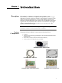
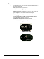
Components for the CoolSNAP™ camera system are listed as follows:
•
•
•
•
Camera
Interface hardware (high-speed digital LVDS or IEEE-1394 data-transfer
interface card)
Data cable (connects camera and interface hardware)
Software discs (PVCAM® drivers included)
CoolSNAP Camera with Test Lens
CoolSNAP IEEE-1394 Cable
CoolSNAP LVDS Cable
CoolSNAP IEEE-1394 Interface Card
CoolSNAP LVDS Interface Card
1
The CoolSNAP User Manual is divided into five chapters. It is suggested that you
read the entire manual before operating the camera in order to ensure proper
use. The chapters that follow this introduction are:
About This
Manual
Precautions
•
System Installation — Instructions for installing the camera system’s
hardware and software.
•
Operating Features — Descriptions of specific camera features.
•
Troubleshooting — Answers to camera system problems.
•
Basic Specifications — Specifications for CoolSNAP components.
The CCD and other system electronics are extremely sensitive to electrostatic
discharge (ESD). To avoid permanently damaging the system, please observe
the following precautions:
Environmental
Requirements
•
This is a Class A product. In a domestic environment, this product may
cause radio interference, in which case, the user may be required to take
adequate measures.
•
If you are using high-voltage equipment (such as an arc lamp) with your
camera system, be sure to turn the camera power on last and power the
camera off first.
•
Never connect or disconnect any cable while the camera system is
powered on (LVDS cameras only).
•
Although you should switch off the camera’s power before disconnecting
the CoolSNAP cable from the DATA connector or the PCI card, you do
not need to power off your computer to detach the cable.
•
Use caution when triggering high-current switching devices (such as an
arc lamp) near your system. The CCD can be permanently damaged by
transient voltage spikes. If electrically noisy devices are present, an
isolated, conditioned power line or dedicated isolation transformer is
highly recommended.
•
Always leave 1/2 inch of space around the camera’s external cooling
fins for air flow.
•
Never open the camera. There are no user-serviceable parts inside the
CoolSNAP camera. Opening the camera voids the warranty.
•
Use only a CoolSNAP data cable and a CoolSNAP interface card with
your CoolSNAP camera. Using a different cable or interface card may
result in permanent damage to your system.
•
Do not use a screw longer than 1/4 inch (6.3 mm) in the camera’s tripod
mounting hole.
•
Do not use a C-mount lens having optics that extend farther than .47
inches (11.9 mm) behind the flange of the lens.
The CoolSNAP camera system should be operated in a clean, non-condensing
environment.
The camera system’s ambient operating temperature is 15°C to 30°C.
2
CoolSNAPcf / CoolSNAPcf / CoolSNAPEZ / CoolSNAPES
2
2
Storage
Requirements
Store the CoolSNAP camera system in its original containers. To protect the
system from excessive heat, cold, and moisture, store at an ambient temperature
between 0°C and 70°C with a relative humidity of 0%-80% noncondensing.
Microscopes and
Lenses
The camera has a standard threaded video mount and can be mounted to any
microscope that accepts a standard C-mount adapter. The camera also allows
you to install any lens that is compatible with a standard threaded video mount
as long as its optics do not extend farther than .47 inches (11.9 mm) behind the
flange of the lens. See Additional Measurements on page 17 for more information.
Note: In microscopy applications, a 0.5x C-mount camera coupler is recommended for an
expanded field of view.
Repairs
The CoolSNAP camera system contains no user-serviceable parts. Repairs must
be done by Photometrics. Should your camera system need repair, contact
Photometrics Customer Service. Please save the original packing materials so
you can safely ship the camera system to another location or return it for repairs
if necessary.
Note: Do not open the camera. Opening the CoolSNAP camera voids the warranty.
Cleaning
Clean exterior surfaces of the camera with a dry, lint-free cloth. To remove
stains, contact Photometrics Customer Service.
To clean the camera’s imaging window, use only a filtered compressed-air
source. Do not touch the window.
Chapter 1. Introduction
3
If you have any questions about your camera system, contact Photometrics
Customer Service. When you call, please have your Photometrics sales order
number or equipment serial numbers available.
Photometrics
Customer Service
•
•
•
•
Tel:
Fax:
Email:
Mail:
800. 874.9789/520.889.9933 between 8:00 am and 5:00 pm MST
520.295.0299
[email protected]
Photometrics
3440 East Britannia Drive
Tucson, Arizona 85706
In Europe, you can reach Customer Service at:
BENELUX
• Tel:
• Fax:
• Email:
• Mail:
FRANCE
• Tel:
• Fax:
• Email:
• Mail:
GERMANY
• Tel:
• Fax:
• Email:
• Mail:
31.347.324989
31.347.324979
[email protected]
Roper Scientific, BV
Ir. D.S. Tuijnmanweg 10
4131 PN VIANEN, Netherlands
33.160.86.03.65
33.160.86.07.09
[email protected]
Roper Scientific, SARL
Z.I. Petite Montagne Sud
4, rue de l'Oisans - C.E. 1702
91017 Evry Cedex, France
49.89.660.779.3
49.89.660.779.50
[email protected]
Roper Scientific, GmbH
Rosenheimer Landstr. 87
D-85521 Ottobrunn, Germany
In Japan, you can reach Customer Service at:
• Tel:
81.3.5639.2731
• Fax:
81.3.5639.2775
• Email: [email protected]
• Mail: Nippon Roper, K.K.
Sakurai Building
2-8-19 Fukagawa
Koto-ku, Tokyo
Japan 135-0033
General product information and answers to some customer service questions can
be found on our website: http://www.photomet.com
4
CoolSNAPcf / CoolSNAPcf / CoolSNAPEZ / CoolSNAPES
2
2
Chapter 2.
System Installation
Carefully review the Precautions section on page 2 before performing any of the
procedures outlined here. Again, use only a CoolSNAP cable and a CoolSNAP interface
card with your CoolSNAP camera. Using a different cable or interface card may result in
permanent damage to your system.
Introduction
Your CoolSNAPcf , CoolSNAPcf , CoolSNAPEZ, or CoolSNAPES camera system has
the following hardware components:
2
•
Camera
•
Data cable
•
Interface card
2
CoolSNAP system components are linked by the data cable and controlled by
your host computer system. All of these hardware components should be
included with your shipment. Refer to the information and figures in System
Components on page 1.
The CCD you selected is installed in your camera.
Keep all the original packing materials so you can safely ship the CoolSNAP
system to another location or return it for service if necessary.
If you have any difficulty with any step of the instructions, call Photometrics
Customer Service.
Software
Compatibility
Requirements
Host Computer
Requirements
The CoolSNAP package includes an image-capture software program designed
for use with your CoolSNAP camera.
All other imaging software must also be PVCAM-compatible. For full access to
imaging software functions, the most current version of PVCAM must be used.
The host computer (PC) for your CoolSNAP camera must have the following:
•
•
•
•
•
•
Windows® 2000 or XP operating system
1 GHz Pentium® 4 (or greater)
256 MB RAM (or greater)
CD-ROM drive
At least one unused PCI or PCI-X card slot
16-bit color display (or greater)
5
If you are a Mac user, the host computer for your CoolSNAP camera must have
the following:
Multiple Cameras
•
Macintosh OS X.3 (Panther)
•
512 MB RAM (or greater)
•
CD-ROM drive
•
At least one unused PCI or PCI-X card slot
•
Video adapter that supports 24-bit color (millions of colors)
Windows versions of PVCAM support multiple open cameras. In order to use this
function, it must also be supported by your imaging software. Many imaging
packages support multiple open cameras.
If your imaging software supports multiple cameras, there must be a separate
PCI card for each camera.
PVCAM for Macintosh and PVCAM for Linux do not support the multiple open
camera feature.
Software
Installation
An Installation Guide appropriate to your system is included with your camera
system. This guide provides step-by-step instructions for installing the camera
interface software and the application software for Windows-based and
Macintosh-based computers. Additional instructions are included for installing
a PCI card in your computer and capturing images.
The Photometrics CD-ROM contains the following files.
•
•
•
•
Installing the
Interface Card
Linux directory — this directory contains the files for installation on a
Linux PC.
Mac OS directory — this directory contains the files for installation on a
Macintosh computer.
Manuals directory — this directory contains user manuals in PDF
format.
Win OS directory — this directory contains the files for installation on a
Windows PC.
You will be using a CoolSNAP interface card to allow the camera to
communicate with your computer.
Refer to the Readme text files on the CD-ROM and to the Software Installation
insert before installing the interface card.
After installing the interface card, proceed to Connecting your CoolSNAP Camera
on page 7.
6
CoolSNAPcf / CoolSNAPcf / CoolSNAPEZ / CoolSNAPES
2
2
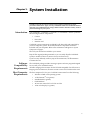
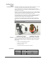
Connecting Your
CoolSNAP
Camera
The CoolSNAP cable connects your CoolSNAP camera to the interface card. This
cable is designed to serve as a conduit both for data and power.
CoolSNAP IEEE-1394 Cable
CoolSNAP LVDS Cable
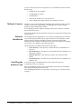
To connect your CoolSNAP LVDS camera:
1.
Connect either end of the CoolSNAP LVDS cable to the CoolSNAP interface
card that you have installed in the host computer.
2.
Connect the other end of the CoolSNAP LVDS cable to the DATA connector
located on the back of the camera (shown below).
The following connectors and display lights, as well as the power switch, are
located on the back of the CoolSNAP camera.
•
DATA connector: 20-pin, high-density connector for data transfer and
power.
•
EXPOSE OUT connector: BNC connector; the signal at the BNC
connector will go to a TTL high level when the exposure begins; useful
for synchronizing an external shutter in the illumination pathway; will
not power the shutter.
•
XFER display light: amber LED illuminates during data transfer.
•
ON display light: green LED illuminates when camera is powered on.
•
POWER switch: momentary on/off rocker switch (CoolSNAPcf /
CoolSNAPcf ) or standard rocker switch (CoolSNAPEZ / CoolSNAPES ).
2
2
Note: CoolSNAP LVDS cameras draw power from the PCI bus via the PCI card.
Therefore, the computer must be powered on for the CoolSNAP LVDS camera to
operate.
Chapter 2. System Installation
7
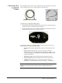
To connect your CoolSNAP IEEE-1394 camera:
1.
Connect either end of the CoolSNAP IEEE-1394 cable to the CoolSNAP
IEEE-1394 interface card that you have installed in the host computer.
2.
Connect the other end of the CoolSNAP IEEE-1394 interface cable to either
DATA connector located on the back of the camera (shown below).
The following connectors and display lights are located on the back of the
CooSNAP camera.
•
DATA connectors: 6-pin IEEE-1394 connectors for data transfer and
power.
•
EXPOSE OUT connector: BNC connector; the signal at the BNC
connector will go to a TTL high level when the exposure begins; useful
for synchronizing an external shutter in the illumination pathway; will
not power the shutter.
•
XFER display light: amber LED illuminates during data transfer.
•
PWR display light: green LED illuminates when camera is powered on.
•
EXT PWR connector: 5.5 x 2.1 mm DC jack for auxiliary CoolSNAP
power supply.
Note: CoolSNAP IEEE-1394 cameras draw power from the IEEE-1394 bus or from the
external power supply.
If no power exists on the IEEE-1394 bus, the external power supply must be used.
In either case, the camera does not supply power to other devices connected to the IEEE1394 bus.
8
CoolSNAPcf / CoolSNAPcf / CoolSNAPEZ / CoolSNAPES
2
2
Chapter 3.
Common Features
Operating Features
The features described in this section are identical in all four CoolSNAP
cameras. Features that are specific to the CoolSNAPEZ and CoolSNAPES cameras
are described separately in the "CoolSNAPEZ / CoolSNAPES " section.
2
2
Readout Speed
Binning
All four CoolSNAP cameras operate at 20-MHz digitization and offer greater
than 10 full frames per second.
All cameras support 1x, 2x, 3x, 4x, and 8x binning in the serial (horizontal)
direction and flexible binning in the parallel (vertical) direction. Binning
increases the frame rate and sensitivity but at the expense of resolution.
Choosing a smaller region of interest (ROI) further increases the frame rate.
CoolSNAPEZ /
CoolSNAPES
Features
The following subsections describe features that are specific to CoolSNAPEZ and
CoolSNAPES camera systems.
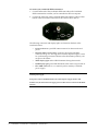
Dual Mode Operation
A unique feature of the CoolSNAPEZ and CoolSNAPES is that they allow two
different CCD clocking modes that let you choose between speed and NIR
sensitivity. In the PVCAM implementation, the clocking modes are referred to as
"normal" and "alternate normal".
2
Normal mode
2
2
In "Normal" mode, the CCD is optimized for maximum anti-blooming protection
and frame rate. In this mode, the CCD can be clocked so that exposure and readout
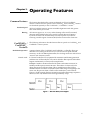
happen simultaneously as shown in the example below.
Example: Consider a situation where the full frame readout time is 90 msec (at
20 MHz) and the exposure time is 200 msec. The readout of a frame will occur
during the exposure of the next frame. This is possible because the CCD has
alternate columns of sensitive and masked areas. While charge is integrating in the
sensor area, the previous frame, which is in the masked area, can be read out
(Figure 1). In this example, the time required to acquire the three-image sequence is
690 ms (3 x 200 + 90) and the frame rate is approximately 4.3 fps.
Figure 1. Normal Mode, Overlapped
9
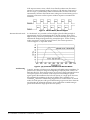
If the exposure time is 50 ms, which is less than the readout time, the camera
operates in "nonoverlapped" mode (see Figure 2). The effective frame rate for
this is 7.14 fps (1/[0.05+0.090]). While in normal mode, the camera firmware
automatically calculates the readout times, taking into account binning and/or
subregion, and carries out the exposure-readout sequence to maximize the
frame rate.
Figure 2. Normal Mode, Nonoverlapped
Alternate Normal mode
In "Alt-Normal", it is possible to achieve higher QE in the NIR (peak QE of
approximately 65%) by manipulating the CCD clock voltages. Also, in this
high-sensitivity mode, the preamplifier is switched off during the exposure to
eliminate the background generated by preamplifier glow. In this clocking
mode, irrespective of what the exposure time is, the camera operates in
"nonoverlapped" or "sequential" mode.
Figure 3. QE for Normal and Alternate Normal Modes
Antiblooming
Typically, interline CCD devices are designed with antiblooming capabilities. To
prevent excess electronic charge from migrating to adjacent pixels, "drains" are
built into the CCD. These drains remove any excessive charge generated from an
overexposed pixel. Sony interline CCDs will prevent blooming for optical
signals greater than 1000 times the full-well capacity of a single pixel. However,
the extended QE capabilities of the Sony ICX285 in the CoolSNAPEZ and
CoolSNAPES reduce the antiblooming suppression for certain modes. In normal
mode, the CCD operates with typical antiblooming suppression. But in alternate
normal mode, the enhanced sensitivity causes a reduction in antiblooming to
greater than 100 times single-pixel full-well capacity.
2
10 CoolSNAPcf / CoolSNAPcf / CoolSNAPEZ / CoolSNAPES
2
2
Application Examples
Example 1
"I have a CoolSNAPEZ (or CoolSNAPES ) and want to operate the camera in the
most sensitive setting for taking high-resolution, single images."
2
For this application, the camera should be operated in "alternate normal" mode
to provide the best quantum efficiency and the camera gain should be set to 2.
These settings will operate the camera in its most sensitive mode.
Example 2
"I would like to acquire sequences of images with a CoolSNAPEZ (or
CoolSNAPES ) to study time-correlated phenomena. My light level is fairly high
and I want to optimize the acquisition rate of the camera."
2
First, the camera speed should be set to 20 MHz. In addition, the camera should
be put into "normal" mode to take advantage of the overlapping of the readout
with the integration time. Finally, the "clearing" mode of the camera should be
set to "clear pre-sequence" to remove the clearing overhead between frames. Of
course, reducing the region of interest and increasing binning will always
increase the frame rate further.
Chapter 3. Operating Features
11
Chapter 4.
Troubleshooting
If you have any difficulty while troubleshooting, or do not see your camera system’s
symptoms listed here, contact Photometrics Customer Service.
System Does Not
Boot Normally
New Hardware
Found Dialog Box
Does Not Appear
(Windows
2000/XP)
Green LED Does
Not Illuminate
(Camera Has No
Power)
If your operating system does not boot normally after you have installed a
interface card, try installing the new card in another open interface slot. If this
does not work:
1.
Turn off your computer and remove the newly installed interface card.
2.
Turn your computer back on. If your system boots normally, there is
probably an interrupt conflict between a previously installed expansion card
and the interface card that you are installing.
3.
If you need assistance resolving the interrupt conflict, contact Photometrics
Customer Service.
If the New Hardware Found dialog box does not appear after installing a new
interface card to your computer and booting Windows 2000/XP:
•
Check to make sure that the new interface card is inserted in a PCI slot
according to your computer manufacturer’s instructions and that the
Photometrics disc is in the host computer’s CD drive.
•
It is possible that there is a conflict between the new interface card and a
previously installed expansion card. With the computer’s power turned off,
remove any previously installed expansion cards that your system does
not need to function. (If you are unsure which cards can be safely
removed, call Photometrics Customer Service.) Then turn your
computer back on and boot Windows 2000/XP again.
•
If the New Hardware Found dialog box still does not appear, contact
Photometrics Customer Service.
If the green LED on the back of the camera does not illuminate when the power
switch is pressed to the ON position:
Check to make sure that the host computer has power:
•
If it does not, power the computer on and then switch on the
camera.
•
If it does, power off the computer, check all system connections
(particularly both ends of the data cable), power the computer back on,
and then switch on the camera again.
•
If you are using a CoolSNAP camera with an IEEE-1394 interface,
connect only one camera at a time to the IEEE-1394 interface card.
•
If the camera still does not have power, contact Photometrics
Customer Service.
12
Images Not
Displayed
Properly
If the amber LED on the back of the camera does not illuminate while images are
being acquired and no images appear:
•
Confirm that the green LED on the back of the camera is illuminated,
indicating that the camera is powered on. See Green LED Does Not
Illuminate (Camera Has No Power) on page 12.
•
Confirm that the correct CoolSNAP camera is selected in your imaging
software application.
•
Power off the camera and the host computer and check all system
connections (particularly both ends of the data cable). Restart. If the
amber LED on the back of the camera does illuminate while images are
being taken, but no images appear:
•
Confirm that Windows is set for at least 16-bit colors.
•
Confirm that the camera is operational by taking an image with a
standard C-mount lens attached to your CoolSNAP. Using normal
room lighting, place the camera on a table about 3 meters away
from an object and acquire an image using your system’s Brightfield
settings.
If the problem persists, contact Photometrics Customer Service.
Bright Spots in
Image / Increased
Background Noise
Camera Running
Too Warm
If you notice bright spots (hot pixels) in the image or an increase in background
noise, take another calibration image and then re-acquire the original image.
PVCAM Error
Message Appears
If a PVCAM error message appears, note the message’s number code and
contact Photometrics Customer Service.
Lengthy Pauses
During Imaging
It is normal for the camera to be slightly warm to the touch while in operation.
However, if the camera is more than slightly warm to the touch (and at least 1/2
inch of space has been left around the external cooling fins for air flow), switch
off the camera immediately and contact Photometrics Customer Service.
If you notice lengthy pauses marked by a lot of disk activity while imaging:
•
Close any other programs that may be running.
•
Install more physical memory to your computer system.
13
IEEE-1394
CoolSNAP
Camera Will Not
Image When
Attached to
Certain Dualprocessor or
Hyperthreadingcapable PCs
Some high-end Windows 2000/XP-enabled computers with Intel Pentium or
Xeon™ processors include a memory enhancement called Physical Address
Extension (PAE). PAE allows these computers to address memory above 4GB;
however, when PAE is enabled the IEEE-1394 CoolSNAP camera will not
transmit any pixel data.
To determine whether your computer is running with PAE enabled, go to the
Control Panel and open the "System" icon. Under the "General" tab, you will
find a reference to Physical Address Extension in the "Computer" section.
To disable PAE, you must edit your C:\boot.ini file and remove the /PAE flag.
14 CoolSNAPcf / CoolSNAPcf / CoolSNAPEZ / CoolSNAPES
2
2
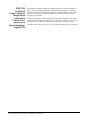
Chapter 5.
Basic Specifications
Dimensions
CoolSNAP Camera: Front View
CoolSNAP LVDS Camera: Side View
15
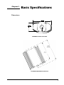
CoolSNAP IEEE-1394 Camera: Side View
16 CoolSNAPcf / CoolSNAPcf / CoolSNAPEZ / CoolSNAPES
2
2
CCD
Specifications
and Orientations
CoolSNAPcf / CoolSNAPcf2
CoolSNAPEZ
CoolSNAPES2
Image Type
Color and Mono
Mono
Mono
Array
Sony ICX205AK (color)
Sony ICX205AL (mono)
Sony ICX285AL
Sony ICX285AL
Resolution
1392 x 1040
1392 x 1040
1392 x 1040
Pixel Size
4.65 µm x 4.65 µm
6.45 µm x 6.45 µm
6.45 µm x 6.45 µm
Digitization Rate
20 MHz
20 MHz
20 MHz
Readout Noise
10 e- rms @ 20 MHz
8 e- rms at 20 MHz
7 e- rms at 20 MHz
Cooling
Thermoelectric, 5°C
below ambient temp
Thermoelectric, 5°C
below ambient temp
Thermoelectric, 0°C
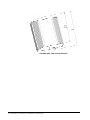
CCD Orientation, LVDS Camera
CCD Orientation, IEEE-1394 Camera
Additional
Measurements
Camera weight: 1.9 lb. (863 g)
Safe C-mount depth: .47 in. (11.9 mm)
Flange focal distance: .69 in. (17.5 mm)
17
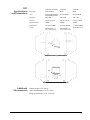
Detector
Rear Panel Description
The following connectors, display lights, and controls are located on the back of
the cameras (pictured below).
DATA connector: for data transfer and power
•
LVDS cameras: 20-pin, high-density connector
•
IEEE-1394 cameras: 6-pin IEEE-1394 connector
EXPOSE OUT connector: BNC connector; the signal at the BNC connector will
go to a TTL high level (+ 5 V) when the exposure begins; useful for
synchronizing an external shutter in the illumination pathway; will not power
the shutter
XFER display light: amber LED illuminates during data transfer
ON display light (LVDS camera)/PWR display light (IEEE-1394 cameras):
green LED illuminates when camera is powered on
POWER switch (LVDS cameras only): standard rocker switch
EXT PWR connector (IEEE-1394 cameras only): 5.5 x 2.1-mm DC jack for
auxiliary CoolSNAP power supply
CoolSNAP LVDS Rear Panel
CoolSNAP IEEE-1394 Rear Panel
18 CoolSNAPcf / CoolSNAPcf / CoolSNAPEZ / CoolSNAPES
2
2
Auxiliary Power
Supply
Usage Requirements
The auxiliary CoolSNAP power supply (shown below) provides power to your
CoolSNAP camera, but is required only under certain conditions.
If your CoolSNAP camera is connected to an IEEE-1394 port that does not
supply power (such as a 4-pin connector on a laptop computer) you need to use
the auxiliary power supply.
The data ports on the CoolSNAP camera do not pass power. If the CoolSNAP
camera is connected in a daisy chain configuration, and it is not the first device
in the daisy chain, you need to use the auxiliary power supply.
If the CoolSNAP camera is connected to a PC that supplies power through the
6-pin IEEE-1394 port, the auxiliary power supply is not needed; however,
connecting the power supply will not damage the camera.
CoolSNAP ES only: The power supply is required for camera cooling. If the
power supply is not connected, the fan will not turn and the camera will not
cool.
2
Warning: Use the auxiliary power supply that shipped with your system ONLY. Do
not use third-party power supplies.
CoolSNAPES2 Power Supply
CoolSNAPEZ Power Supply
Installation
The auxiliary power supply ships with four unique wall plugs. You need to
install one of the plugs on the power supply before using it. Select the correct
plug for your wall socket and press it into the power supply. The supplied
plugs include:
•
NEMA 1-15 for North America/Japan
•
BS1363/A for United Kingdom
•
EN50075 for Europe
•
AS/NZS 3112-1993 for Australia/New Zealand
Specifications
CoolSNAPES2
Input Voltage
Output Voltage
Output Current (Max)
All other CoolSNAP IEEE-1394 cameras
100-240 VAC / 47-63 Hz
9V
12 VDC
3.3 A
1250 mA
Chapter 5. Basic Specifications
19
BENELUX
Roper Scientific, BV
Ir. D.S. Tuijnmanweg 10
4131 PN VIANEN, Netherlands
tel: 31.347.324989
fax: 31.347.324979
email: [email protected]
JAPAN
Nippon Roper, K.K.
Sakurai Building,
2-8-19 Fukugawa
Koto-ku, Tokyo
Japan 135-0033
tel: 81.3.5639.2731
fax: 81.3.5639.2775
email: [email protected]
FRANCE
Roper Scientific, SARL
Z.I. Petite Montagne Sud
4, rue de l'Oisans - C.E. 1702
91017 Evry Cedex, France
tel: 33.160.86.03.65
fax: 33.160.86.07.09
email: [email protected]
GERMANY
Roper Scientific, GmbH
Rosenheimer Landstr. 87
D-85521 Ottobrunn, Germany
tel: 49.89.660.779.3
fax: 49.89.660.779.50
email: [email protected]
USA
Photometrics
3440 East Britannia Drive
Tucson, Arizona 85706
tel: 800.874.9789 or 520.889.9933
fax: 520.295.0299
email: [email protected]
57-061-001 Rev H0