1
EKI-6538
8-port 10/100 Mbps
Industrial Smart Ethernet Switch
User Manual
Copyright
The documentation and the software included with this product are copyrighted 2006 by Advantech Co., Ltd. All rights are reserved. Advantech
Co., Ltd. reserves the right to make improvements in the products
described in this manual at any time without notice. No part of this manual may be reproduced, copied, translated or transmitted in any form or
by any means without the prior written permission of Advantech Co., Ltd.
Information provided in this manual is intended to be accurate and reliable. However, Advantech Co., Ltd. assumes no responsibility for its use,
nor for any infringements of the rights of third parties, which may result
from its use.
Acknowledgements
Intel and Pentium are trademarks of Intel Corporation.
Microsoft Windows and MS-DOS are registered trademarks of
Microsoft Corp.
All other product names or trademarks are properties of their respective
owners.
Part No. 2003653800
1st Edition
Printed in Taiwan
June 2006
EKI-6538 User Manual
ii
Product Warranty (2 years)
Advantech warrants to you, the original purchaser, that each of its products will be free from defects in materials and workmanship for two years
from the date of purchase.
This warranty does not apply to any products which have been repaired or
altered by persons other than repair personnel authorized by Advantech,
or which have been subject to misuse, abuse, accident or improper installation. Advantech assumes no liability under the terms of this warranty as
a consequence of such events.
Because of Advantech’s high quality-control standards and rigorous testing, most of our customers never need to use our repair service. If an
Advantech product is defective, it will be repaired or replaced at no
charge during the warranty period. For out-of-warranty repairs, you will
be billed according to the cost of replacement materials, service time and
freight. Please consult your dealer for more details.
If you think you have a defective product, follow these steps:
1.
Collect all the information about the problem encountered. (For
example, CPU speed, Advantech products used, other hardware
and software used, etc.) Note anything abnormal and list any
onscreen messages you get when the problem occurs.
2.
Call your dealer and describe the problem. Please have your manual, product, and any helpful information readily available.
3.
If your product is diagnosed as defective, obtain an RMA (return
merchandize authorization) number from your dealer. This allows
us to process your return more quickly.
4.
Carefully pack the defective product, a fully-completed Repair and
Replacement Order Card and a photocopy proof of purchase date
(such as your sales receipt) in a shippable container. A product
returned without proof of the purchase date is not eligible for warranty service.
5.
Write the RMA number visibly on the outside of the package and
ship it prepaid to your dealer.
iii
Declaration of Conformity
CE
This product has passed the CE test for environmental specifications. Test
conditions for passing included the equipment being operated within an
industrial enclosure. In order to protect the product from being damaged
by ESD (Electrostatic Discharge) and EMI leakage, we strongly recommend the use of CE-compliant industrial enclosure products.
FCC Class A
Note: This equipment has been tested and found to comply with the limits
for a Class A digital device, pursuant to part 15 of the FCC Rules. These
limits are designed to provide reasonable protection against harmful
interference when the equipment is operated in a commercial environment. This equipment generates, uses, and can radiate radio frequency
energy and, if not installed and used in accordance with the instruction
manual, may cause harmful interference to radio communications. Operation of this equipment in a residential area is likely to cause harmful interference in which case the user will be required to correct the interference
at his own expense.
Technical Support and Assistance
Step 1. Visit the Advantech web site at www.advantech.com/support
where you can find the latest information about the product.
Step 2. Contact your distributor, sales representative, or Advantech's customer service center for technical support if you need additional
assistance. Please have the following information ready before
you call:
- Product name and serial number
- Description of your peripheral attachments
- Description of your software (OS, version, software, etc.)
- A complete description of the problem
- The exact wording of any error messages
EKI-6538 User Manual
iv
Safety Instructions
1.
Read these safety instructions carefully.
2.
Keep this User's Manual for later reference.
3.
Disconnect this equipment from any AC outlet before cleaning.
Use a damp cloth. Do not use liquid or spray detergents for cleaning.
4.
For plug-in equipment, the power outlet socket must be located
near the equipment and must be easily accessible.
5.
Keep this equipment away from humidity.
6.
Put this equipment on a reliable surface during installation. Dropping it or letting it fall may cause damage.
7.
The openings on the enclosure are for air convection. Protect the
equipment from overheating. DO NOT COVER THE OPENINGS.
8.
Make sure the voltage of the power source is correct before connecting the equipment to the power outlet.
9.
Position the power cord so that people cannot step on it. Do not
place anything over the power cord.
10.
All cautions and warnings on the equipment should be noted.
11.
If the equipment is not used for a long time, disconnect it from the
power source to avoid damage by transient overvoltage.
12.
Never pour any liquid into an opening. This may cause fire or electrical shock.
13.
Never open the equipment. For safety reasons, the equipment
should be opened only by qualified service personnel.
14.
If one of the following situations arises, get the equipment checked
by service personnel:
a. The power cord or plug is damaged.
b. Liquid has penetrated into the equipment.
c. The equipment has been exposed to moisture.
d. The equipment does not work well, or you cannot get it to work
according to the user's manual.
e. The equipment has been dropped and damaged.
f. The equipment has obvious signs of breakage.
v
15.
DO NOT LEAVE THIS EQUIPMENT IN AN ENVIRONMENT
WHERE THE STORAGE TEMPERATURE MAY GO BELOW
-10° C (14° F) OR ABOVE 70° C (158° F). THIS COULD DAMAGE THE EQUIPMENT. THE EQUIPMENT SHOULD BE IN A
CONTROLLED ENVIRONMENT.
Safety Precaution - Static Electricity
Follow these simple precautions to protect yourself from harm and the
products from damage.
1.
To avoid electrical shock, always disconnect the power from your
PC chassis before you work on it. Don't touch any components on
the CPU card or other cards while the PC is on.
2.
Disconnect power before making any configuration changes. The
sudden rush of power as you connect a jumper or install a card may
damage sensitive electronic components.
EKI-6538 User Manual
vi
Contents
Chapter
1 Introduction ..................................................... 2
1.1
1.2
1.3
1.4
1.5
1.6
Chapter
Features ............................................................................ 2
Feature Summary .............................................................. 4
Specifications .................................................................... 5
Packing List....................................................................... 7
Ordering Information ........................................................ 7
Safety Precaution............................................................... 7
2 Installation ..................................................... 10
2.1
Overview ........................................................................ 10
2.2
LED Indicators ................................................................ 11
2.3
Dimensions...................................................................... 12
2.4
Figure 2.1:Overview of EKI-6538 ............................... 10
Table 2.1:EKI-6538 LED Definition ........................... 11
Figure 2.2:Front View of EKI-6538 ........................... 12
Figure 2.3:Side View of EKI-6538 .............................. 13
Figure 2.4:Bottom View of EKI-6538 ......................... 13
Mounting ......................................................................... 14
2.4.1
2.4.2
Chapter
Panel Mounting ............................................................ 14
Figure 2.5:Combine the Metal Mounting Kit .............. 14
Figure 2.6:Attach EKI-6538 to the Wall ..................... 15
DIN Rail Mounting ...................................................... 16
Figure 2.7:Installation to DIN Rail Step 1 ................... 16
Figure 2.8:Installation to DIN Rail Step 2 ................... 17
Figure 2.9:Installation to DIN Rail Step 3 ................... 18
2.5
2.6
Network Connection ....................................................... 18
Power Connection ........................................................... 19
2.7
Digital Inputs & Outputs ................................................. 20
2.8
RS-232 Connection ......................................................... 21
Figure 2.10:Pin Assignment of the Power Connector . 19
Figure 2.11:Digital I/O Pin Assignment ...................... 20
Figure 2.12:Digital Output Connection ....................... 20
Figure 2.13:RJ-48 (10-pin) to DB9 (F) Cable ............. 21
3 Configuration................................................. 24
3.1
RS-232 Console .............................................................. 24
3.1.1
3.1.2
Figure 3.1:Open Hyper Terminal ................................ 24
Figure 3.2:COM Port Properties Setting ...................... 25
Figure 3.3:Login Screen: RS-232 Configuration ......... 25
Figure 3.4:RS-232 Console Configuration .................. 26
Networking Configuration .......................................... 26
Figure 3.5:Network Configuration of RS-232 ............. 26
Password Configuration ............................................... 27
Figure 3.6:Error Message in Password Configuration . 27
vii
Table of Contents
3.1.3
3.1.4
3.2
Web Browser................................................................... 29
3.2.1
3.2.2
3.2.3
3.2.4
3.2.5
3.2.6
3.2.7
3.2.8
3.3
System Restart ............................................................. 28
Figure 3.7:Restart EKI-6538 ........................................ 28
Factory Reset ............................................................... 28
Figure 3.8:Default Setting via 232 Configuration ....... 28
Figure 3.9:EKI-6538 Web Login Page ........................ 29
Figure 3.10:Function Overview Page .......................... 30
Basic Configuration ..................................................... 30
Figure 3.11:System Setting .......................................... 31
Figure 3.12:ARL Aging Time Setting ......................... 32
Figure 3.13:DI/DO Setting .......................................... 33
Figure 3.14:Port Status ................................................ 33
Figure 3.15:Port Configuration .................................... 35
Figure 3.16:Port Statistics Overview ........................... 35
Figure 3.17:Detail Statistics of Specific Port ............... 36
VLAN Configuration ................................................... 36
Figure 3.18:VLAN Mode Setting ................................ 36
Figure 3.19:Default Port-based VLAN Setting Screen 37
Figure 3.20:Port-based VLAN Setting ........................ 38
Figure 3.21:IEEE 802.1Q VLAN Setting .................... 39
Address Configuration ................................................. 39
Figure 3.22:Port Security Configure ............................ 39
Figure 3.23:Setup the MAC Security Address Table .. 40
Port Trunk .................................................................... 40
Figure 3.24:Port Trunk Setting .................................... 41
Port Mirroring .............................................................. 41
Figure 3.25:Port Mirror Setting ................................... 41
QoS (Quality of Service) ............................................. 42
Figure 3.26:QoS Setting ............................................. 42
Bandwidth Administration ........................................... 43
Figure 3.27:Rate Limitation Setting ........................... 43
Figure 3.28:Storm Control Setting Page ...................... 44
Firmware Upgrade ....................................................... 44
Figure 3.29:Firmware Upgrade .................................... 44
Self Diagnosis ................................................................. 45
EKI-6538 User Manual
Figure 3.30:Self-Diagnosis .......................................... 45
viii
CHAPTER
1
2
Introduction
Sections include:
• Features
• Feature Summary
• Specifications
• Packing List
• Ordering Information
• Safety Precaution
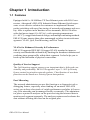
Chapter 1 Introduction
1.1 Features
Equipped with 8 x 10/100Base-TX Fast Ethernet ports with RJ-45 connectors, Advantech’s EKI-6538 Industrial Smart Ethernet Switch represents a cost-effective solution for customers to implement Ethernet
packet switching with easy fine-tuning of network performance and security. Able to operate in the harshest of environments, EKI-6538 offers
wide dual power input (10~48 VDC), wide operating temperatures
(0 ~ 60° C), a rugged mechanical design, and multiple mounting methods.
EKI-6538 runs smarter than other unmanaged switches in network management: VLAN, QoS, Port Mirroring, and Port Trunk.
VLANs for Enhanced Security & Performance
EKI-6538 supports IEEE 802.1Q tagged VLAN standard to improve
security and bandwidth utilization by limiting the broadcast domains and
confining intra-group traffic within their segments. It also helps you to
break up the limitation of physical connections.
Quality of Service Support
The QoS function support ensures your important data is delivered consistently and predictably. EKI-6538 supports Layer 2 - 802.1p Priority
Queue control to prioritize network packets. Classification of user data
priorities can be based on a Priority Queue data packets.
Port Mirroring
The network administrator can use this function as a diagnostic tool or
debugging feature, especially when fending off an attack. EKI-6538
assists you to keep close track of switch performance and alter it if necessary. Port mirroring can be managed locally or remotely. The administrator places a protocol analyzer on the port receiving the mirrored data to
monitor each segment separately. The analyzer captures and evaluates the
data without affecting the client on the original port.
EKI-6538 User Manual
2
Port Trunks for Aggregated Bandwidths
The network administrator can use port mirroring as a diagnostic tool or
debugging feature, especially when fending off an attack. EKI-6538
assists you to keep close track of switch performance and alter it if necessary. To expand the network, you can use EKI-6538’s port trunks function to combine ports together to create multi-link load sharing,
aggregated bandwidths to a server or a network backbone.
Easy Diagnosis & LED indicators
EKI-6538 provides a quick and easy way of troubleshooting by using the
push button and LED indicator. You can easily determine which port has
failed, the link condition, transmission rate, and power status when diagnosing problems in the field. Complex configuration and test equipment
is not needed because the specially designed front panel interface helps
you quickly conform whether or not a port has failed by using the push
button and “FAULT” LED indicator.
3
Chapter 1
1.2 Feature Summary
• Provides 8 x 10/100 Mbps Ethernet ports with RJ-45 connector
• Provides push button for port diagnostic
• Supports web browser for configuration
• Supports RS-232 console for basic factory setting
• Supports IEEE 802.1Q tagged VLAN
• Supports IEEE 802.1p QoS for traffic classification and prioritization
• Supports ports aggregation, aggregated ports auto failed over and load
balance per trunk
• Supports port mirroring for traffic monitoring
• Provides port configuration for auto-negotiation setting of speed/flow
control
• Supports MDI/MDI-X auto crossover
• Supports ingress/egress rate control per port & broadcast storm protection
• Supports MAC-based security per port
• Supports traffic statistic monitor per port
• Embedded with memory buffer, supports store-and-forward transmission
• Supports dual +10 ~ 48 VDC power input
• Provides surge protection (EFT) 3000 VDC for power line
• Provides ESD protection 4000 VDC for Ethernet ports
• Supports operating temperature: 0 ~ 60° C
• Provides flexible mounting options: DIN rail, panel
EKI-6538 User Manual
4
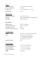
1.3 Specifications
Communications
Compatibility
IEEE 802.3, 802.3u, 802.3x, 802.1p, 802.1Q
LAN
10/100Base-TX
I/O Type
2 Digital Input:
Logic Level 0 : close to GND
Logic Level 1 : open
2 Digital Output:
Open collector to 30V, 200mA (Max.load)
Transmission Distance
100 m
Transmission Speed
Up to 100 Mbps
Interface
Connectors
8 x RJ-45 (Ethernet)
5-pin removable screw terminal (DI/DO)
LED Indicators
Power, P-Fail, Fault, Link, 10/100 Mbps
Console
RS-232 (RJ-48)
Network Management
Diagnostics
Push button for port diagnostic
Port Mirroring
Real-time traffic statistic
VLAN
IEEE 802.1Q tagged VLAN
Port-based VLAN
Configuration
Web browser & RS-232 console management
Speed/duplex auto-negotiation
Security
MAC-based security per port
Traffic Control
IEEE 802.1p QoS
IEEE 802.3ad Link Aggregation
Rate limit and storm control
IEEE 802.3x flow control
5
Chapter 1
Power
Power Connectors
7-pin removable screw terminal
Power Consumption
Max. 7 W
Power Input
2 x Unregulated +10 ~ 48 VDC
Fault Output
Present
Mechanism
Dimensions (WxHxD)
46 x 162 x 126 mm
Enclosure
IP30, ABS+PC with solid mounting kits
Mounting
DIN35 rail, Wall
Protection
ESD Protection
4,000 V DC (Ethernet)
Surge Protection (EFT)
3000 V DC (Power)
Power Reversal Prt.
Present
Overload Current Protection
4A/125V
Certifications
Safety
UL 60950-1, CAN/CSA-C22.2 No.60950
EMC
U.S.A.: FCC Part 15 CISPR 22
EU: EN55011, EN55022 Class A,
EN61000-3-2/3, EN55024
IEC61000-4-2/3/4/5/6/8/11
Ingress Protection
IP30
Environment
Operating Humidity
20 ~ 95% (non-condensing)
Operating Temperature
0 ~ 60° C (32 ~ 140° F)
Storage Humidity
0 ~ 95% (non-condensing)
Storage Temperature
-10 ~ 70° C (14 ~ 158° F)
MTBF
230,000 hrs
EKI-6538 User Manual
6
1.4 Packing List
• 1 x EKI-6538 Smart Ethernet Switch
• 1 x INET CD-ROM
• 1 x Panel mounting bracket
• 1 x 1m RJ-48 to female DB9 cable (for EKI series console configuration)
1.5 Ordering Information
EKI-6538
8-port Industrial 10/100Mbps Smart Ethernet Switch
1.6 Safety Precaution
Attention!
If DC voltage is supplied by an external circuit,
please use a protection device on the power supply
input.
7
Chapter 1
EKI-6538 User Manual
8
CHAPTER
2
2
Installation
Sections include:
• Overview
• LED Indicators
• Dimensions
• Mounting
• Network Connection
• Power Connection
• Digital Inputs & Outputs
• RS-232 Connection
Chapter 2 Installation
In this chapter, you will be given an overview of the EKI-6538 hardware
installation procedures.
2.1 Overview
1.
10/100 Mbps T(X) Port
2.
10/100 Mbps LED Indicator (Green)
3.
Link Status LED Indicator (Yellow)
4.
Power Status LED Indicator (Red)
5.
Model Name
6.
Power Fail LED Indicator (Red)
7.
Link Port Fail LED Indicator (Red)
8.
Link Port Diagnose Push Button
9.
7-pin Terminal Block for P1, P2, Relay and Grounding
10.
5-pin Terminal Block for 2-ch DI/DO
11.
Heat Dissipation Hole
12.
DIN Rail Install Mechanism
13.
Product Information Label
14.
Grounding Spring
15.
RS-232 Console
Figure 2.1: Overview of EKI-6538
EKI-6538 User Manual
10
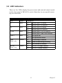
2.2 LED Indicators
There are few LEDs display the power status and network status located
on the front panel of EKI-6538, each of them has its own specific meaning as below table.
Table 2.1: EKI-6538 LED Definition
LED
Color
Description
P1
Red
On
Off
Power input 1 is inactive
P2
Red
On
Power input 2 is active
Off
Power input 2 is inactive
On
Power input 1 or 2 is inactive
Off
Power input 1 and 2 are inactive
On
Link ports fail
Off
Link ports are normal
On
Connecting to network
Flash
Data is transmitting/receiving
Off
Not connect to network
On
Link to 100 Mbps network
Off
Link to 10 Mbps network
P-Fail
Red
FAULT
Red
LINK
(Port 1~8)
10/100
(Port 1~ 8)
Yellow
Green
Power input 1 is active
11
Chapter 2
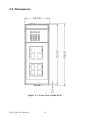
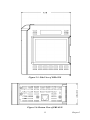
2.3 Dimensions
Figure 2.2: Front View of EKI-6538
EKI-6538 User Manual
12
Figure 2.3: Side View of EKI-6538
Figure 2.4: Bottom View of EKI-6538
13
Chapter 2
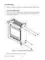
2.4 Mounting
EKI-6538 supports two different mounting methods: Panel & DIN Rail.
2.4.1 Panel Mounting
EKI-6538 can be wall mounted by using the included metal mounting kit.
First, use the screws included in the package to combine the EKI-6538
and metal mounting kit.
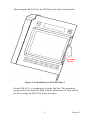
Figure 2.5: Combine the Metal Mounting Kit
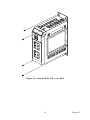
Then, screw the whole device to the wall.
EKI-6538 User Manual
14
Figure 2.6: Attach EKI-6538 to the Wall
15
Chapter 2
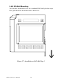
2.4.2 DIN Rail Mounting
You can also mount EKI-6538 on a standard DIN Rail by below steps.
First, pull down the kit in the back of EKI-6538
Figure 2.7: Installation to DIN Rail Step 1
EKI-6538 User Manual
16
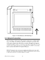
Then, hang the EKI-6538 to the DIN Rail with angle of inclination.
Figure 2.8: Installation to DIN Rail Step 2
Put the EKI-6538 at a right angle with the Din Rail. The grounding
spring in the back should be flush with the aluminum rail. Then pull up
the kit to wedge the EKI-6538 firmly into place.
17
Chapter 2
Figure 2.9: Installation to DIN Rail Step 3
2.5 Network Connection
EKI-6538 has 8 x RJ-45 ports that support connection to 10 Mbps Ethernet, or 100 Mbps Fast Ethernet, and half or full duplex operation. EKI6538 can be connected to other hubs or switches through a twisted-pair
straight through the cable or a crossover cable up to 100m long. The connection can be made from any port of the EKI-6538 (MDI-X) to another
hub or switch either MDI-X or uplink MDI port.
EKI-6538 supports auto crossover to make networking more easy and
flexible. You can connect any RJ-45 (MDI-X) station port on the switch
to any device such as a switch, bridge or a router.
EKI-6538 User Manual
18
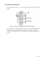
2.6 Power Connection
EKI-6538 supports dual +10 ~ 48 VDC power inputs and power-fail relay
output.
Figure 2.10: Pin Assignment of the Power Connector
You can connect an alarm indicator, buzzer or other signaling equipment
through the relay output. The relay opens if power input 1 or 2 fails.
("Open" means if you connect relay output with a LED, the light would
be off)
19
Chapter 2
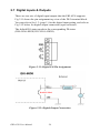
2.7 Digital Inputs & Outputs
There are two sets of digital input/outputs that the EKI-6538 supports.
Fig 2.11 shows the pin assignment top view of the DI/O terminal block.
You can refer to Sec 1.3 (page 5 ) for the digital input setting, and refer to
Fig 2.12 below for digital output connection (open collector).
The default DO status equals to the corresponding DI status
(DI0=DO0=HIGH, DI1=DO1=HIGH).
Figure 2.11: Digital I/O Pin Assignment
Figure 2.12: Digital Output Connection
EKI-6538 User Manual
20
Note:
Grounding and wire routing can help you to limit
the effects of noise due to electromagnetic interference (EMI). Connect the ground screw to the
grounding surface while you wire the power connection and Digital I/O.
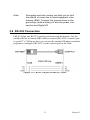
2.8 RS-232 Connection
EKI-6538 has one RS-232 console port located on the bottom. Use the
included RJ-48 to female DB9 cable to connect EKI-6538’s console port
to your PC’s COM port, then you can use the standard Windows terminal
program to configure EKI-6538 via the console port in the field.
Figure 2.13: RJ-48 (10-pin) to DB9 (F) Cable
21
Chapter 2
EKI-6538 User Manual
22
CHAPTER
3
2
Configuration
Sections include:
• RS-232 Console
• Web Browser
• Self Diagnosis
Chapter 3 Configuration
The EKI-6538 can be confiigured in two ways: via RS-232 Console or a
web browser.
3.1 RS-232 Console
EKI-6538’s RS-232 console is designed for field-site rapidly configure,
only provide below functions--networking configuration (IP Address,
Subnet Mask, Default Gateway), password setting, system restart and
back to factory default setting.
Use the included accessory RJ-48 to female DB9 cable to connect EKI6538 and your host PC.
From the Windows desktop, click:
Start /Programs/Accessories/Communications/HyperTerminal
to open Hyper Terminal program.
Figure 3.1: Open Hyper Terminal
EKI-6538 User Manual
24
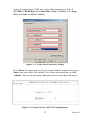
Select the appropriate COM port, and set the parameter as Fig.3.2
(115200 for Baud Rate, 8 for Data Bits, None for Parity, 1 for Stop
Bits, and None for Flow Control)
Figure 3.2: COM Port Properties Setting
Press Enter for login screen. (If you can not find the login screen, press
Enter one more time) The default User Name and password are both
“admin”. Key-in the user name and password to enter the main menu.
Figure 3.3: Login Screen: RS-232 Configuration
25
Chapter 3
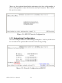
There are four options found in the main menu, just key-in the number in
front of the options to enter the function, and you can press Esc to back
the previous menu.
Figure 3.4: RS-232 Console Configuration
3.1.1 Networking Configuration
You can configure the basic networking setting here. Just key-in the number in front of the options then enter the networking setting.
Figure 3.5: Network Configuration of RS-232
EKI-6538 User Manual
26
Warning
After pressing Enter, you will find the networking
setting in the screen has been changed, but you
still have to press “S” to save your changes
before escaping this screen.
Warning
The wrong message will show while you set “0”
for the first segment of the subnet mask and
default gateway (000.xxx.xxx.xxx).
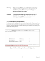
3.1.2 Password Configuration
In the password configuration, you need to key-in the old password, new
password and confirm the new password to finish the password change
process. An error message will be shown if you want to save before you
finish the whole process.
Figure 3.6: Error Message in Password Configuration
27
Chapter 3
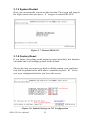
3.1.3 System Restart
Here you can restart the system via this function. The screen will jump to
the login screen when you press “ 1 ” to agree to restart EKI-6538.
Figure 3.7: Restart EKI-6538
3.1.4 Factory Reset
If you forget your setting or the setting becomes disorderly, this function
can make one or all settings go back to the default.
Choose the item you want to go back to default setting, your configuration will be updated in the table above, remember to press “ E “ to execute your configuration before you leave this screen.
Figure 3.8: Default Setting via 232 Configuration
EKI-6538 User Manual
28
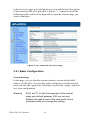
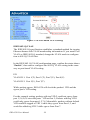
3.2 Web Browser
EKI-6538 provides a convenient configure way via web browser, you can
follow below step to access EKI-6538.
EKI-6538’s default IP is 10.0.0.1, make sure your host PC and EKI-6538
are on the same logical sub-network.
Warning
Your host PC should be in the same VLAN setting with EKI-6538, or the management will not
be configured.
Connect EKI-6538 to the Ethernet, then your host PC could configure it
via Ethernet. Or you can directly connect EKI-6538 to your host PC with
a straight-through or cross over Ethernet cable.
Open Internet Explorer and type EKI-6538’s IP in the Address field, then
press Enter to open the web login page.
Figure 3.9: EKI-6538 Web Login Page
Default user name and password are both admin, fill in the username and
password then press OK to enter the configuration. You can change the
password in the system setting.
29
Chapter 3
In the Overview page, you can find the overview and the brief description
of the functions EKI-6538 provided. Click the “+” symbol to unroll the
hiding hyperlink, and click the hyperlink to open the function page you
want to configure.
Figure 3.10: Function Overview Page
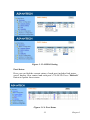
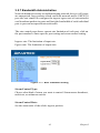
3.2.1 Basic Configuration
System Settings
In this page, you can find the current firmware version and the MAC
address of EKI-6538. You can also make configuration for the network,
password and ARL aging time. Remember to press the “Apply” button to
save your configuration.
Warning
Don't set "0" for the first segment of the subnet
mask and default gateway (000.xxx.xxx.xxx)
Refresh the web screen if the web could not be
displayed while you change the setting.
EKI-6538 User Manual
30
Figure 3.11: System Setting
ARL aging time ( 0~ 1048575)
Aging time is counted from the last time that the switch saw the MAC
address. The default value is 300 seconds. That means if EKI-6538
doesn’t receive the packet from the specific MAC address for 300 seconds, this MAC address will be removed from ARL table. EKI-6538 will
broadcast the following packets from this MAC address, learn and record
the behavior again until rebuild it into ARL table.
If you disable the ARL aging function, EKI-6538 will not record or
remember any MAC address while its MAC address table capacity is full.
Packets coming from the MAC address outside the existed MAC address
table would be broadcast to all ports.
31
Chapter 3
Figure 3.12: ARL Aging Time Setting
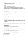
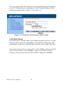
DI/DO Setting
By simply setting up a web-based configuration, you can manage the connection between two digital inputs and two digital outputs that are built
into EKI-6538. These are invaluable when integrating field indicators or
alarm devices that will respond to messages according to individual
user’s configured setting.
The DI/O default setting of EKI-6538 is ---DI0=DO0=HIGH; DI1=DO1=HIGH.
The number with blue boldface character means the current DI/O status
(1=HIGH, 0=LOW), you can press the Refresh button to update it.
DO can be decided by the logic result of both DI, or assigned HIGH/
LOW directly. Choose the option in the pull down list of "Assign DO"
and "Logic" columns for your prefer setting.
Output from DI : DO equals to the logic result of the checked DI
Invert from DI: DO equals to the opposite logic result of the checked DI
Warning:
If you choose "Output from DI" or "Invert from
DI", please remember to check the DI behind.
EKI-6538 User Manual
32
Figure 3.13: DI/DO Setting
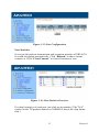
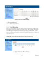
Port Status
Here you can find the current status of each port, includes link status,
speed, duplex, flow control and each port’s VLAN ID. Press “Refresh”
button to update latest status.
Figure 3.14: Port Status
33
Chapter 3
Click on the number to configure the port. Press “Apply” to save you
configuration before leave this page.
Admin
Enable: Transmit and receive packets
Disable: Reject packets transmission and reception (LED indicators
would be lit always if you do not remove the cable even though you disable this function)
Auto Negotiation
Enable: Speed and Duplex are auto-negotiated by the connecting devices
Disable: Speed and Duplex must be set by manual.
Speed Duplex
Set the same speed/duplex in the network area, or the communication
may have problems.
Flow Control
Enable: When the flow is over loading, system would send out a frame to
suspend the data transmission. That will control the flow effectively without packet loss
Disable: No flow control and might cause packet loss while over loading.
Default Priority
Set up the priority of the packet from this port (0~7)
Default Port VID
Add 802.1Q VLAN tag to the ingress packet without 802.1Q VLAN tag.
If the packet ingress to this port without default VLAN tag, EKI-6538
will add the VID tag to this packet as you set here.
This tag not only include the 802.1Q VLAN ID, the priority information
were included also.
EKI-6538 User Manual
34
Figure 3.15: Port Configuration
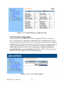
Port Statistics
Overview the packets transmission and reception statistics of EKI-6538.
It would not update automatically. Click “Refresh” to show current
counter, or Click “Clear Counter” to clear all counter to zero.
Figure 3.16: Port Statistics Overview
For detail statistics of each port, just click on its number. (The "N/A"
symbol in the TX packets statistcs is NORMAL due to the chip limitation.)
35
Chapter 3
Figure 3.17: Detail Statistics of Specific Port
3.2.2 VLAN Configuration
Virtual Local Area Network (VLAN) is a group of devices on one or
more LANs that are configured so that they can communicate as if they
were attached to the same wire, when in fact they are located on a number
of different LAN segments. Because VLANs are based on logical instead
of physical connections, it is very flexible for user/host management,
bandwidth allocation and resource optimization. Packets can not be
transmitted and received in different VLAN. EKI-6538 provides two
different VLAN modes for network management.
Figure 3.18: VLAN Mode Setting
EKI-6538 User Manual
36
Port-based VLAN
If you set the VLAN mode to Port-based VLAN, each physical switch
port is configured with an access list specifying membership in a set of
VLANs.
You could find the status in the Port-based VLAN configuration page
show “Enable”. The default VLAN ID for each port is “1”.
Warning:
QoS function would be "Disable" while Portbased VLAN function is "Enable"
Figure 3.19: Default Port-based VLAN Setting Screen
To configure the port-based VLAN, you have to choose the VLAN ID
from the pull down menu first. Second, choose the port member for this
VLAN ID via click the icon under the port number. Finally, don’t forget
to click Apply to finish your setting for this VLAN ID.
Fig 3.20 shows ports 2 & 3 belong to the same VLAN group — VID= 2.
Warning:
The default VID=1 should be removed or
changed before you configure the port-based
VLAN. If you didn't remove or change it,
default VID=1 would allow packets transmitted
and received between all ports, and your
optional configuration would be ineffective.
37
Chapter 3
Figure 3.20: Port-based VLAN Setting
IEEE 802.1Q VLAN
The IEEE 802.1Q specification establishes a standard method for tagging
Ethernet frames with VLAN membership information. If you want to set
VLAN as IEEE 802.1Q standard, change the VLAN mode to configuration to 802.1Q VLAN first.
In the IEEE 802.1Q VLAN configuration page, confirm the status shows
“Enable”, then start to configure the 802.1Q VLAN setting in the same
way as port-based VLAN setting.
EX:
VLAN ID 1: Port 1(T), Port 2 (T), Port 7(U), Port 8(U)
VLAN ID 2: Port 3(U), Port 7(T)
While packets egress, EKI-6538 will check the packets’ VID and the
egress port’s VID setting.
For the example setting, packets with tag VID 2 could not egress from
port 1,2,4,5,6,8 since the ports’ VID are not 2; Packets with tag VID 1
could only egress from port 1,2,7,8. Meanwhile, packets without default
VID would be tagged as VID 1 while they egress from Port 1,2, and
would be added tag VID 2 while egress from Port 7.
EKI-6538 User Manual
38
Figure 3.21: IEEE 802.1Q VLAN Setting
Warning
A. Default VLAN ID (1) couldn’t be removed.
B. The port your PC connecting can not be set as
“Tag” or “Not member”.
3.2.3 Address Configuration
Enable the port security function, the port with “Enable” status would
only allow the packets from the MAC address in the “MAC Security
Address Table” to ingress EKI-6538.
Figure 3.22: Port Security Configure
39
Chapter 3
Users can input static MAC address for corresponding port to the table as
Fig 3.23. Each port has its independent “MAC Security Address Table”,
and the maximum MAC number of each table is 4.
Figure 3.23: Setup the MAC Security Address Table
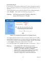
3.2.4 Port Trunk
Port trunk allows multiple links to be bundled together and act as a single
physical link for increased throughput. It provides load balancing, and
redundancy of links in a switched inter-network. (For example Fig 3.24):
Set switch A ports 6 & 8 as same trunk 1 with 100Mbps, and set switch B
ports 6 & 8 as trunk 2 with 100Mbps, connect port 6 and 8 of both
switches, then the speed of the trunk would be doubled as 200Mbps.
EKI-6538 User Manual
40
Figure 3.24: Port Trunk Setting
• SA: Source Address
• DA: Destination Address
3.2.5 Port Mirroring
Port mirroring allows one port of the switch to monitor the traffic transmitted/received by the other port of the switch. The network administrator with a protocol analyzer is allowed to capture packets from mirror
port to evaluate and monitor without affecting the operation of clients on
the original port.
Enable the mirror function then start to setup the mirroring.
Figure 3.25: Port Mirror Setting
41
Chapter 3
3.2.6 QoS (Quality of Service)
Quality of Service ensures critical data is delivered consistently and predictably. EKI-6538 supports Layer 2 802.1p priority queue control to prioritize network packets depending on customer’s needs. The feature of
QoS is useful in improving determinism.
Fig 3.26 shows the EKI-6538 QoS configuration page. Setting the corresponding table of the packet default priority (0~7) and the switch
Queue(0~3). As WRR mode rule, each Queue will transmit packets as the
weight number (1~31) in turn.
Warning
Default Weight of Queue (0,1,2,3) = 1,2,4,8,
Higher priority queue weight cannot be smaller
than a lower one.
Figure 3.26: QoS Setting
EKI-6538 User Manual
42
3.2.7 Bandwidth Administration
Network broadcast storms or malfunctioning network devices will generate unexpected, large packets which can block network traffic. EKI-6538
provides rate control to configure the ingress/egress rate of unicast/multicast/broadcast packets in parts and limit the bandwidth of each individual
port to prevent unexpected network traffic.
The rate control page shows current rate limitation of each port, click on
the port number to enter specific port setting and storm control setting.
Ingress rate: The limitation of input rate.
Egress rate: The limitation of output rate.
.
Figure 3.27: Rate Limitation Setting
Storm Control Type:
Choose what kind of storm you want to control. Storm means broadcast,
multicast, or unknown unicast.
Storm Control Rate:
Set the storm ratio of the whole ingress packets.
43
Chapter 3
Figure 3.28: Storm Control Setting Page
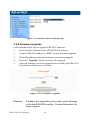
3.2.8 Firmware Upgrade
Following the below step to upgrade EKI-6538 firmware.
1.
Download the firmware from ADVANTECH website.
2.
Connect EKI-6538 and press “YES” to start firmware upgrade.
3.
Fill in the path to getting the firmware you want to upgrade.
4.
Press the “Upgrade” button to process the upgrade.
5.
After the firmware has been upgraded successfully, the EKI-6538
will reboot and the buzzer will ring.
Figure 3.29: Firmware Upgrade
Warning
If broken, the upgrade process may cause damage
to the the EKI-6538 module. Contact Advantech for
repair support
EKI-6538 User Manual
44
3.3 Self Diagnosis
EKI-6538 comes with a self-diagnosis button (on the top of the module)
and front-viewable LEDs for field troubleshooting. Without the need for
extra tools, you can recognize the hardware status of the Ethernet port
instantly through one single button.
If you find the link status or the LED indicator status is abnormal, you can
use the self-diagnosis button for self-diagnosing. Press the button while
EKI-6538 is working for few seconds (1~3 sec) until the LEDs turn off
temporary. The LEDs will be shining when the self-diagnosis is going.
After few seconds, the LEDs will back to normal status and the FAULT
LED will be lit if one of the linked ports fail. User can easily determine if
the abnormal problem caused from EKI-6538.
Figure 3.30: Self-Diagnosis
45
Chapter 3
EKI-6538 User Manual
46