1
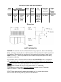
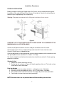
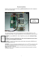
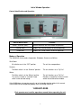
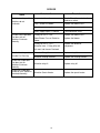
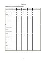
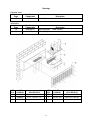
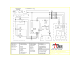
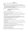
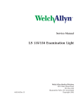
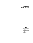
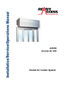
AA300
Access Air 300
Heated Air Curtain System
TABLE OF CONTENT
Topic
Page
Disclaimer
Serial Number Identification
Contact Sheet
Introduction
Product Information
Description
Specifications
Dimensions
Safety Information
Installation Procedures
Physical Installation
Electrical Installation
Operations
Control Identification and Operations
Modes of Operation
Maintenance
Maintenance Schedule
Daily
Monthly
Yearly
Service
Troubleshooting Guide (Cause and Effect)
Parts Lists
Complete Parts List (Description/Part Number)
Drawings - Exploded Views / Schematics
Appendix “A” – Heater Assembly Replacement
3
3
3
4
2
4
5
5
5
6
7
8
8
9
9
9
10
11
12
14
DISCLAIMER
Ready Access Disclaims any Liability for any damage or harm caused to the AA300 Air Curtain,
It’s Operator or any other equipment however caused if the AA300 Air Curtain is repaired or
serviced by anyone other than an authorized service engineer or Contrary to the manufacturers
written instruction contained herein.
This manual is intended for use by the in-house or authorized field service engineers and sales
representatives
The manufacturer maintains the right to update, add or issue a new service manual at any time
without notice, thereby rendering all previous issues obsolete.
Please write the Serial Number and Installation Date for your drive-thru window in the spaces
provided.
SERIAL NUMBER
Date of Installation
CONTACT INFORMATION
For sales and service contact
Tel: 630-876-7766
Tel: 800-621-5045
Fax: 630-876-7767
Website: www.ready-access.com
Ready Access
1815 Arthur Drive
West Chicago, Illinois 60185
Email: [email protected]
3
INTRODUCTION
The Ready Access AA300 Pass-Thru Air Curtain System is designed to be an integral part of
your drive-thru operation by providing comfort for both operator and customer during the coldest
of days as well as satisfying health department codes for fly fan application.
PRODUCT INFORMATION
Modes of Operation
The Ready Access AA300 Pass-thru Air Curtain System is versatile in function and design,
offering operators four separate modes of operation.
* Outside warm air flow only
* Inside warm air flow only
* Both outside and inside warm airflow
* Outside fly fan operation only
Features and Benefits
Satisfies heath department requirements for "Fly Fan" applications while it reduces and deflects
the amount of outside wind blowing into the building. This also reduces heating and airconditioning loss as well as reducing unwanted environment factors such as dust and exhaust
fumes from entering the building. Acts as a fly fan to deter insects from entering the building
during warm weather conditions.
Provides the owner/operator with a stable, comfortable working environment for all
crewmembers. Reduces Drive-Thru operation expenses by diminishing employee turnover.
Unique Design
The AA300 Air Curtain System is the only system on the market today that offers an outside and
inside heated airflow. It is designed for use with any flush mount window.
Quality Construction
The exterior housing of the AA300 Air Curtain System is manufactured using bronze or clear
anodized aluminum.
Fully Assembled, Ready to Install
The Access Air 300 system is shipped completely pre-assembled and ready for installation,
lowering installation costs. Normal installation for new store construction takes less than two
hours.
Three to Five Day Shipping
Ready Access will ship any standard Access Air 300 System in 3 to 5 days from receipt of
order.
Warranty and Service Support
Your Access Air 300 System comes with a one year limited warranty on parts and labor. In
addition, each Pass-Thru Air Curtain System is backed by a nationwide service organization.
AVAILABLE OPTIONS
Power coat painting is available upon request for a wide range of custom colors.
4
SPECIFICATIONS AND PERFORMANCE
Model
Number
AA300
Unit Voltage
USA
International
208/240
VAC
60Hz
Single
Phase
220/240
VAC
50/60 Hz
Single
Phase
Heater
Watts
Actual
Unit
Amps
Air
Velocity
Dimensions
In Inches
WxHxD
Weight
In
Shipping
Carton
7100
W
32 A
WINTER
600FPMSUMMER
800 FPM
at
Nozzle
See Below
85 lbs
Dimensions
Figure 1
SAFETY INFORMATION
WARNING: To avoid the risk of fire, Electric Shock or injury to persons, observe the following:
Before servicing or cleaning the unit, switch the power off at the mechanical switch near the unit
(Installed by an Electrician) or the electrical entry service panel/circuit breaker. (Load Center)
OSHA LOCK OUT – TAG OUT procedures are to be observed to prevent power from being
switched on accidentally.
Any Installation and / or Electrical work must be done by QUALIFIED persons in accordance
with all applicable codes / standards and manufacturers recommendations and specifications.
DO NOT insert fingers and / or foreign objects into the Air Curtain.
DO NOT block or tamper with the unit in any manner while it is in operation.
This product must not be used in Potentially Dangerous locations such as Flammable,
Explosive Chemical – laden environment.
DO NOT attach duct work to this product or attempt to use it as a make-up air heater.
Such use voids the warranty and may create unsafe conditions.
5
Installation Procedures
PHYSICAL INSTALLATION
Before you begin installing your Ready Access Air Curtain, you must determine what type of
installation will be required. Wood Frame, Masonry Framing, etc. See the illustration below to
determine your rough opening size and mounting.
Warning: Two people are required for the lifting and installation of the air curtain.
Figure 2
CONFIRM THAT THE CUSTOMER-SUPPLIED FRAME IS MADE TO ACCOMMODATE THE
DIMENSIONS AS ILLUSTRATED ABOVE.
Confirm that AC power has been run and is ready for connection to the Air Curtain.
Check shipping carton for any shipping damage and remove Air Curtain from the carton.
Check Air Curtain for any shipping damage.
Once the application has been determined, check the daylight opening of the frame being used.
The opening dimensions should be 47 ¾” wide x 16 ¼” high.
The electric should be installed from the breaker box (Load Center) to the Air Curtain opening
before the installation.
Window Air Unit
1. Remove the Outside cover from the unit.
2. Position the unit as shown in Figure #2. Note the position of the unit. The inside surface
should be flush with the window
From the Outside
3. Secure the unit to the window with the 6 – self-tapping screws. (Provided)
4. Secure the unit to the building with the 4 - #12 x 3” long screws. (Provided)
5. Run a bead of caulk around air curtain to seal all gaps to prevent water penetration.
6. Caulk heads of screws to prevent water penetration.
NOTE: Clearance holes are not provided due to different building constructions.
6
Electrical Installation
All power must be connected and wired by a qualified electrician and must be in compliance
with all state and local codes.
Terminal Block
AC Input
Match wires
Color for Color
The incoming AC power line must be connected to the terminal block located in tray. (Per
Standard electrical code.) The green “grounding” wire is to be attached to the frame of the unit.
WARNING: Use only 208/240 VAC – 60Hz / Single Phase source with a dedicated 40 Amp
circuit.
WARNING: This must be a dedicated circuit. Other electrical equipment must not share
the same line from the 40Amp circuit breaker.
WARNING: Turning off the front panel rocker switches does not remove the 208/240 volts of
electrical power form the unit
WARNING: To disconnect the power completely from this unit, turn OFF the mechanical switch
near the unit (Installed by an Electrician) or the electrical entry service panel/circuit breaker
panel (Load Center) for this unit.
OSHA LOCK OUT – TAG OUT procedures are to be observed to prevent power from being
switched on accidentally.
7
Initial Window Operation
Control Identification and Operation
Switch Identification
Winter / Summer (Main)
Function
Switches between the three modes of operation.
Outside Heat
Enables the “Outside Heater” for Winter operation
Inside Heat
Enables the “Inside Heater” for Winter operation.
Modes of Operation
The AA300 has three modes of operation. Shutdown, Summer and Winter.
Shut Down:
All switches are in the “OFF” position.
The unit has no operations.
Summer
The Main switch is in the “Summer” position.
The unit functions as a “Fly Fan”.
Winter
The Main switch is in the “Winter” position.
The unit functions as a “Fly Fan”.
Turn on the “Inside” or “Outside” heater
switch to the desired setting.
Provides a heated Air Curtain to inside
and/or the outside of the window.
If the AA300 does not operate correctly, go to the troubleshooting guide in this manual.
If the AA300 still do not operate properly, then call Ready Access at
1-800-621-5045
Each operator must read the operations manual before operating the unit.
8
Maintenance
Maintenance Schedule
Scheduled maintenance should be performed on a regular basis. This is to assure proper
operation and performance of the AA300 Air Curtain.
DAILY
Check the air vents and ducts for foreign materials. (Anything that might cause restricted air flow
or damage to the air curtain.)
MONTHLY
Follow safety procedures before opening the unit.
Check the interior of the unit for any build up of any foreign materials using a dry cloth.
NOTE: KEEP ANY LIQUIDS OFF THE INTERIOR COMPONENTS.
Clean moving parts and lubricate with silicone or Teflon spray.
NOTE: Do NOT use Grease or Oils
SEMI ANNUAL (6 Months)
Check all electrical and mechanical parts for proper operations
YEARLY
Have a service technician come in and perform a maintenance check on the unit.
IF NEEDED, CONTACT YOUR READY ACCESS SERVICE AGENT FOR SERVICE.
WARRANTY:
Ready Access will only accept responsibility for manufacturing defects in the
product’s construction and/or materials.
Adjustments required during installation are the responsibility of the installer or
contractor and will not be covered under warranty.
Problems caused by improper installation are the responsibility of the installer or
contractor and will not be covered under warranty.
9
SERVICE
Issue
Probable Cause
Resolution
Both Heaters Inoperable.
No power to the unit.
Switches do not
illuminate.
Check / Reset the main circuit
breaker or switch.
Fuse 1 and/or 2 is blown.
Replace the blown fuse/s.
Defective power supply.
Replace the power supply.
Power supply output is shorted.
Find and correct short.
If Relay #2 LED is “ON”.
Replace the blown fuse/s.
Blown Blower Fuse or Defective
Blower.
Replace the blower.
If Relay #2 LED is “OFF”.
Replace the defective
component.
Outside Heat Inoperable.
Fan does not run.
Switches Illuminate
Normally.
Defective timer 1, Relay #2 or #3
Unit went into thermo Overload.
Outside Heat Inoperable.
Defective Relay #3.
Replace relay #3.
Outside Fan Running.
Defective Heating Element.
Replace the heating element.
Inside Heat Inoperable.
Fan does not run.
Switches Illuminate
Normally.
Defective relay #1.
Replace relay #1.
Defective Quartz Heater.
Replace the quartz heater.
Inside Heat Inoperable.
Inside fan runs. Switches
Illuminate Normally.
10
Parts Lists
Complete Parts List (Description/Part Number)
Description
Bit - Square Drive - Security
Current Part Previous Part
Status
Number
Number
20010006
N/A
Obsolete
Blower Assembly ( New Style ) 85028000
- Dual Speed
Blower Assy - Kit (Old Style
85127800
AA300)
Cover - Outside - Bronze
30100201
39927801,200 Current
10015
39927800
Current
N/A
Current
Cover - Outside - Champagne
30100203
N/A
Current
Cover - Outside - Clear
30100202
N/A
Current
Fan - Kit - Muffin
85127900
39927900
Current
Fuse, .250 AMP (2 per unit)
20110524
N/A
Current
Fuse, 1.0 AMP (1 per unit)
20110523
N/A
Current
Harness Assy Kit - Brz
85129001
39929001
Current
Harness Assy Kit - Clr
85129002
39929002
Current
Heater Assy - Kit - L-R (For
Dual Speed Blower)
Heater Assy - Kit - L-R (Heating
element)
Heater Assy - Kit - R-L (For
Dual Speed Blower)
Heater Assy - Kit - R-L (Heating
element)
Panel Air Shield L/R
85028120
N/A
Current
85127720
39927720
Current
85028110
N/A
Current
85127710
39927710
Current
30227520
N/A
Current
Panel Air Shield R/L
30227510
N/A
Current
PCB CONTROLLER - AA300
(New Style)
Quartz Lamp - Kit
85003000
N/A
Current
85129100
39929100
Current
Relay - 40 Amp
20110513
N/A
Current
Relay - Omron - 10 Amp - 2 pet 20110528
unit.
Rivet
10180009
N/A
Current
N/A
Current
Switch Kit - Summer - Air
Shield
Thermostat - Selco Kisco
85129200
39929200
Current
20110017
N/A
Current
Timer Board Kit
85129300
39929300
Current
Torx Bit - T25 Security
20010001
N/A
Obsolete
11
Note
Drawings
Exploded Views
Part Number
If Applicable
N/A
Unit – Exploded View
Page
13
Part Number
If Applicable
50010161-D
Wiring Diagram
13
N/A
Wiring Diagram
Page
12
Description
Schematics
Description
(New Version)
REF
ID #
1
PART
NUMBER
30100201
DESCRIPTION
Cover – Outside – BR
REF
ID #
2
PART
NUMBER
See Parts List
DESCRIPTION
Heater Assy Kit R/L
1
30100202
Cover – Outside – CL
2
See Parts List
Heater Assy Kit L/R
1
30100203
Cover – Outside - Champ
3
See Parts List
Blower Assembly Kit
12
13
Appendix “A”
Replacement Procedures to Follow When Replacing the Heater Assembly
WARNING!
To reduce the risk of fire, electric shock or injury to persons, observe the following:
1. Before servicing unit, switch power off at the mechanical switch near the unit (installed by electrician) or
electrical entry service panel / circuit breaker. OSHA Lock Out-Tag Out procedures are to be observed
to prevent power from being switched on accidentally.
2. Any installation and/or electric work must be done by Qualified persons in accordance with all applicable
codes / standards and manufactures recommendations.
Tools Needed:
¼” Driver (For removing blower assembly from panel)
Pliers (Aid in removing tight wing nuts from blower assembly)
Wire cutters/strippers
Electrician Tape
1. Remove the outside cover from the unit. (12 screws)
2. Unplug all electrical twist and lock plugs to the heater assembly and blower from the panel.
3. Remove the wire mesh cover if applicable.
4. Remove the blower assembly by unscrewing the (8) wing nuts and the (2) ¼” Hex head screws from the
panel. Remove the blower assembly from the unit and place aside in a safe place. Do not allow the
blower to get wet.
5. Remove the Heater Assembly Cover (Item No.6) by unscrewing the (4) wing nuts.
6. Turn the heater assembly so the back of the assembly is facing up exposing the blue wires to the
thermostat shutoff. Cut the 2 wires leaving enough to splice together to close the circuit. (NOTE: Don’t
worry there are new thermostat shutoffs on the new heater assembly.)
7. Remove the heater assembly from the unit.
8. Remove the replacement heater assembly from the carton.
9. Assemble the heater cover to the heater assembly with the (4) wing nuts. (NOTE: The position of the
threaded studs is up.)
10. Check the position of the screen. Make sure the clearance holes line up with the holes located around
the vent opening.
11. Position the heater assembly such that the heater cover is facing out away and thermostats are in back.
Line up the heater assembly with the holes around the unit vent.
12. Position the wire mesh cover (if applicable) over the opening and secure with the (6) screws.
13. Position the blower assembly over the heater assembly. Secure with the (8) wing nuts to the heater
assembly and the (2) ¼” hex head screws into the panel.
14. Reconnect the blower wires to the wireharness.
15. Replace the outside cover with (12) screws.
16. Turn power on, and follow the operating instructions.
If you need further assistance, call Ready Access Inc service representative at 800-621-5045.
14
NOTES
Ready Access, 1815 Arthur Drive, West Chicago, Illinois 60185, Tel: 630-876-7766, Tel: 800-621-5045
Fax: 630-876-7767, Email: [email protected], Website: www.ready-access.com
AA300 INSTALLATION SERVICE OPERATIONS MANUAL 11_19_08
15
Ready Access, 1815 Arthur Drive, West Chicago, Illinois 60185, Tel: 630-876-7766, Tel: 800-621-5045
Fax: 630-876-7767, Email: [email protected], Website: www.ready-access.com
AA300 INSTALLATION SERVICE OPERATIONS MANUAL 11_19_08
16